

Page 1
,reliobnonoitamrofnignikeesnehW.rotcartnocgnitaehruoyllac,reliobotsriaperroecivresroF
.lebaLgnitaRnonwohssarebmuNlaireSdnarebmuNledoMrelioBedivorp
rebmuNledoMrelioB
____-____NI_
rebmuNlaireSrelioB
_______6
etaDnoitallatsnI
rotcartnoCgnitaeH rebmuNenohP
sserddA
DNAGNITAREPO,NOITALLATSNI
ROFSNOITCURTSNIECIVRES
ECNEDNEPEDNI
®
RELIOBDERIF-SAG
8141049R23.5-4/07 Price - $3.00
Page 2
The New York City Department of Buildings has approved the Independence® Series boiler:
REGNAD
noitautissuodrazahyltnenimminasetacidnI
,htaednitluserlliw,dediovatonfi,hcihw
ytreporplaitnatsbusroyrujnisuoires
.egamad
NOITUAC
noitautissuodrazahyllaitnetopasetacidnI
nitluseryam,dediovatonfi,hcihw
ytreporproyrujnironimroetaredom
.egamad
GNINRAW
noitautissuodrazahyllaitnetopasetacidnI
,htaednitluserdluoc,dediovatonfi,hcihw
ytreporplaitnatsbusroyrujnisuoires
.egamad
ECITON
,noitallatsninosnoitcurtsnilaicepssetacidnI
erahcihwecnanetniamro,noitarepo
yrujnilanosrepotdetalertontubtnatropmi
.sdrazah
NOITUAC
ecnonahtyltneuqerferomreliobsihtotretawddaotyrassecensiti,noitarepolamrongnirud,fI
metsysykaelA.skaelrofmetsysruoykcehcotnaicinhcetecivresdeifilauqatlusnoc,htnoma
netrohsyltnacifingisnachcihwreliobehtotdeilppusretawpu-ekamfoemulovehtesaercnilliw
ehtnehW.negyxodnaslarenimdevlossideraretawpu-ekamnideniartnE.reliobehtfoefileht
ehtdnatnemidessatuollafslarenimehtreliobehtnidetaehsiretawpu-ekamlooc,hserf
tnemidesfonoitalumuccaehT.efilreliobdecudernitlusernachtoB.sagasasepacsenegyxo
noritsacehtsneppahsihtnehW.noritsacehtgnitcatnocmorfretawehtetalosiyllautnevenac
ehtninegyxoeerffoecneserpehT.kcarcyllautneveyamdnatohylemertxestegaeratahtni
nac,hguonehgihsemocebnoitartnecnocehtfi,hcihwerehpsomtaevisorrocasetaercreliob
fotluseraerasepyteruliafesehtforehtienecniS.edisniehtmorfhguorhtnoritsacehtedorroc
tneverpottseretnitsebs'enoyrevenisiti,ylraelC.ylppatonseodytnarrawehttcefedgnitsaca
.sihteveihcaotdohtemtsebehtsiytirgetnimetsysfoecnanetniamehT.eruliaffoepytsiht
ECITON
.launamsihtfokcabehtnodetnirpsihcihwfoypoca,ytnarrawdetimilasahreliobsihT
yltcerroceraslortnocllatahteesotrotcartnocgnillatsniehtfoytilibisnopserehtsitI
.etelpmocsinoitallatsniehtnehwylreporpgnitarepoeradnadellatsni
llewsassecorpgnirutcafunamehtotdetubirttaebyamsnoitcesnoritsacnotsurecafruS
ehttceffatonseoddnalamronsitsurecafruS.egarotsgnirudnoitasnednocsa
reliobafoytivegnolroecnamrofrep
.
Approval No. MEA 154-93-E Vol. III.
The City of New York requires either a Licensed Master Plumber or a Fire Suppression Piping Contractor supervise the
installation of this product.
The Massachusetts Board of Plumbers and Gas Fitters has approved the Independence® Series boiler. See the Massachusetts
Board of Plumbers and Gas Fitters website, http://license.reg.state.ma.us/pubLic/pb_pre_form.asp for the latest Approval
Code or ask your local Sales Representative.
The Commonwealth of Massachusetts requires this product to be installed by a Licensed Plumber or Gas Fitter.
The following terms are used throughout this manual to bring attention to the presence of hazards of various risk
levels, or to important information concerning product life.
2
Page 3

GNINRAW
ehtwolloF.ylefasetarepootecivresdnaecnanetniamralugerseriuqerreliobsihT
.launamsihtnideniatnocsnoitcurtsni
ytreporpesuacnacecnanetniamroecivres,noitaretla,tnemtsujda,noitallatsnireporpmI
erofeblaunameritneehtdnatsrednudnadaeR.efilfossolroyrujnilanosrep,egamad
ebtsumecivresdnanoitallatsnI.ecivresro,noitarepopu-trats,noitallatsnignitpmetta
.ycnegaecivresrorellatsnielbaegdelwonkdna,delliks,decneirepxenaybylnodemrofrep
.detnevylreporpebtsumreliobsihT
snoisivorperaerehtosdellatsniebtsumdnanoitarepoefasrofriahserfsdeenreliobsihT
.rianoitalitnevdnanoitsubmocetauqedarof
ehtfotratsehterofebdenaelcdnadetcepsniebtsummetsysgnitnevehtforoiretniehT
ynarofnosaesgnitaehehttuohguorhtyllacidoirepdetcepsniebdluohsdnanosaesgnitaeh
suoixonwollaotyrassecensimetsysgnitnevdetcurtsbonudnanaelcA.snoitcurtsbo
drawotetubirtnoclliwdnaylefastnevotefilfossolroyrujniesuacdluoctahtsemuf
.ycneiciffes'reliobehtgniniatniam
mirTdnagnipiPehteeS.dellatsnisievlav)feiler(ytefasasselnuetelpmoctonsinoitallatsnI
.sliatedroflaunamsihtfonoitceS
tondnanwodtuhsotreliobehtesuacyamhcihwsecivedytefashtiwdeilppussireliobsihT
metsysgnitaeheht,ytilibissopasisepipnezorfoteudegamadfI.ecivrestuohtiwtrats-er
dluohssmraladnasdraugefasetairporpparo;rehtaewdlocnidednettanutfelebtondluohs
.evitareponisireliobehtfiegamadtneverpotmetsysgnitaehehtnodellatsnieb
epipynawercsnutonoD.erusserprednumaetsroretawtohyrevsniatnocreliobsihT
gnirussaylevitisoptuohtiwreliobsihtfostnenopmocynatcennocsidottpmettaronsgnittif
tnempiuqednagnihtolcevitcetorpraewsyawlA.erusserponsahdnaloocsiretaweht
noylertonoD.seirujnidlacstneverpotreliobsihtgnicivresropugnitrats,gnillatsninehw
ehtfoerutarepmetdnaerusserpehtenimretedotseguagerutarepmetdnaerusserpeht
sireliobehtnehwtohyrevemocebhcihwstnenopmocsniatnocreliobsihT.reliob
.loocerayehtsselnustnenopmocynahcuottonoD.gnitarepo
,animulaniatnocleufehtdnanoitsubmocfostcudorp,noitcurtsnocfoslairetamrelioB
rocixotrehtoro/dnasedyhedla,sedixonegortin,edixonomnobrac,slatemyvaeh,acilis
ehtotnwonkerahcihwdnayrujnisuoiresrohtaedesuacnachcihwsecnatsbuslufmrah
esusyawlA.mrahevitcudorperrehtodnastcefedhtrib,recnacesuacotainrofilaCfoetats
ehtybraengnikrowrognicivresnehwtnempiuqednasrotaripser,gnihtolcytefasreporp
.ecnailppa
.htaedroyrujnilanosrepesuacnacredroreporpehtnisnoitcurtsnillawollofoteruliaF
slaunamsrerutcafunamtnenopmocnideniatnocesohtllagnidulcni,snoitcurtsnilladaeR
rogniniatniam,gnitarepo,pugnitrats,gnillatsnierofebreliobehthtiwdedivorperahcihw
.gnicivres
elbammalfrehtodnaenilosag,slairetamelbitsubmocmorfeerfdnaraelcaerareliobpeeK
.sdiuqilrosropav
.semitllataecalpniebtsumsdraugdnaserusolcne,setalprevocllA
NOITUAC
esehthguohtlA!ecnanetniamdnanoitcepsnilaunnaeriuqersecivedffotucretawwolepyteborP
ehtninoitanimatnocelbissopotdesopxesieborpeht,noitareporiehtnietatsdiloserasecived
,etelpmocrofsnoitcurtsnIecivreSffotuCretaWwoLotrefeR.gniluofottcejbusdnaretawreliob
.snoitcurtsnigninaelcdnanoitcepsnipets-yb-pets
3
Page 4

Figure 1: Dimensional Drawing
4
Page 5
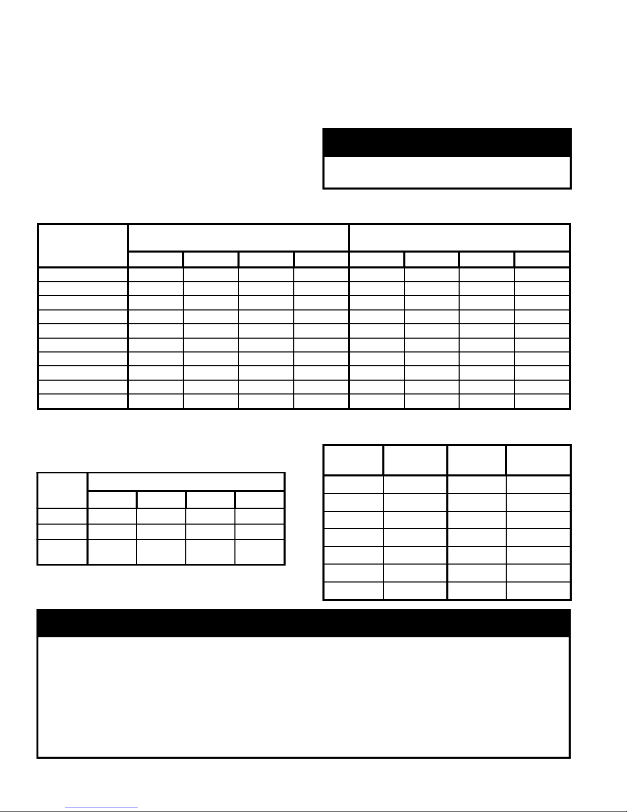
Dimensional Data
relioB
ledoM
.xorppA
gnippihS
thgieW
.sbL
)sehcnini(snoisnemiD
dednemmoceR
dnuoR.niM
eziSyenmihC
)thgieHxretemaiD(
)1(
saG
.nnoC
)TPN(
).laG(emuloVretaW
'A' 'B' 'C' 'D' 'E' 'F' 'G'
maetS
relioB
retaW
relioB
)3(
3NI 053 2/1-41
04
4/3-33 4
4/1-04
4/3-4
4/1-7 .tf51x"4
"2/1
1.5 8.7 9.3
4NI 024 4/3-71 4/3-43 5 8/7-8 .tf51x"5 5.6 0.01 0.5
5NI 584 12
4/3-53 6 4/1-5
2/1-01
.tf51x"6
9.7 2.21 1.6
ASU6NI
555 ¼42 8/1-21
3.9
4.41 2.7
adanaC6NI
4/3-63 7
2/1-7
.tf51x"7
7NI 026 2/1-72 4/3-31
"4/3
7.01 6.61 3.8
ASU8NI
096 4/3-03 8/3-51 1.21 8.81 4.9
adanaC8NI
4/3-73
8 .tf51x"89NI 067 43 71 5.31 0.12 5.01
ASU01NI
518 ¼73
54 4/3-83 2/1-54
8/5-81
"4/3
)2(
9.41 2.32 6.11
01NI
adanaC
9 .tf51x"9
11NI 588 2/1-04 4/1-02 3.61 4.52 7.21
21NI 559 4/3-34 8/7-12 "1 7.71 6.72 8.31
.yenmihCfopototgninepodooHtfarDfomottobmorfsithgiehyenmihc'51)1(
.TPN1si)toliPgnidnatS(noitingIsuounitnoC11NI-01NInoezisnoitcennocsaG)2(
levelffotucretawwolot)levelretawlamron(LWNmorfemulovretaw:"emulovretawelbamaets"s'reliobmaetS)3(
Heating Surface: 4.35 sq. ft. per ueway (steam); 5.72 sq. ft. per ueway (water)
Table of Contents
I. Pre-Installation ...............................7
II. Knockdown Boiler Assembly ..........
III. Semi-Pak Boiler Assembly ............
IV. Packaged Boiler Assembly ............
V. Piping and Trim ...........................
VI. Gas Piping ....................................
9
13
16
17
23
VII. Venting .........................................
VIII. Electrical .......................................
IX. System Start-up ............................
X. Service Instructions ......................
XI. Repair Parts ..................................
XII. Appendix
Low Water Cut Off (LWCO) .......
25
27
60
73
79
102
5
Page 6

Figure 2: Section Tappings
gnippaT
eziS
)TPN(
eborPhtiwrelioBmaetS
.O.C.W.L
htiwrelioBmaetS
.O.C.W.LtaolF
relioBretaW
sselknaThtiwrelioBretaW
retaeH
A 2 ylppuS ylppuS ylppuS ylppuS
B ½
¼othsuB
eguaGerusserP
gulP gulP gulP
C ½ ssalGeguaG
,eguaGnoinU½&elppiN
,woblEteertS.O.C.W.L
timiL&nohpyS
hsuBgnippaTrewoLgulP
gnippaTreppU¼ot
eguaG.pmeT/.sserP
othsuBgnippaTrewoLgulP
gnippaTreppU¼
eguaG.pmeT/.sserP
D 2 nruteR nruteR
,woblE,lpN"3,½1othsuB
,egnalF.criC,lpN"2
nruteRrotalucriC,teksaG
,woblE,lpN"3,½1othsuB
,egnalF.criC,lpN"2
nruteRrotalucriC,teksaG
E ¾
woblEteertS&elppiN"3
evlaVfeileRytefaS
woblEteertS&elppiN"3
evlaVfeileRytefaS
woblEteertS&elppiN"3
evlaVfeileRytefaS
woblEteertS&elppiN"3
evlaVfeileRytefaS
F 2
evlaVniarD¾othsuB
nruteRlanoitpOro/dna
evlaVniarD¾othsuB
nruteRlanoitpOro/dna
ro/dnaevlaVniarD¾othsuB
nruteRytivarGlanoitpO
ro/dnaevlaVniarD¾othsuB
nruteRytivarGlanoitpO
G 2
)6-3NI(deggulPyrotcaF
)6-3NI(ylppuSlanoitpO
)21-7NI(ylppuSderiuqeR
)6-3NI(deggulPyrotcaF
)6-3NI(ylppuSlanoitpO
)21-7NI(ylppuSderiuqeR
)6-3NI(deggulPyrotcaF
)21-7NI(gulP
ylppuSytivarGlanoitpO
)6-3NI(deggulPyrotcaF
)21-7NI(gulP
ylppuSytivarGlanoitpO
H ¾
nohpyS&¼othsuB
timiL
¼othsuB
eguaGerusserP
lleW
timiL
lleW
timiL
J ¾ elbacilppAtoN elbacilppAtoN elbacilppAtoN retaeHsselknaT
K ¾ ffotuCretaWwoL gulP gulP gulP
L 1
deggulPyrotcaF
ffO-wolBecafruS
deggulPyrotcaF
ffO-wolBecafruS
deggulPyrotcaF deggulPyrotcaF
M ¼1
deggulPyrotcaF
nruteRecnaillA
deggulPyrotcaF
nruteRecnaillA
deggulPyrotcaF deggulPyrotcaF
N ¼1
deggulPyrotcaF
ylppuSecnaillA
deggulPyrotcaF
ylppuSecnaillA
deggulPyrotcaF deggulPyrotcaF
P ¾
deggulPyrotcaF
timiLecnaillA
deggulPyrotcaF
timiLecnaillA
deggulPyrotcaF deggulPyrotcaF
Table 1: Trim and Control Installation in Section Tappings
6
Page 7

I. Pre-Installation
GNINRAW
rianoitalitnevdnanoitsubmocetauqedA
reporperussaotdedivorpebtsum
.noitsubmoc
GNINRAW
snoitcurtsniesehtwolloftonoduoyfI
tluseryamnoisolpxeroerifa,yltcaxe
lanosreproegamadytreporpgnisuac
.yrujni
REGNAD
rehtoroenilosagerehwreliobllatsnitonoD
fosecruosro,sdiuqilrosropavelbammalf
,srenaelc,sehcaelb.e.i(snobracordyh
cirbaf,srevomertniap,syarps,slacimehc
.derotsrodesuera).cte,srenetfos
ECITON
,reliobehtfotnetnocretawwolehtoteuD
ehtotdragerhtiwreliobehtfognizis-sim
evissecxenitluserlliwdaolmetsysgnitaeh
tnenopmocdetareleccadnagnilcycreliob
tnarrawTONSEODmahnruB.eruliaf
reliobdezis-simybdesuacseruliaf
otreliobehtezisrevoTONOD.snoitacilppa
.metsyseht
ordinance. See Figure 3 for minimum listed clearance
to combustible material. Recommended service
clearance is 24 inches from left side, right side, and
front. Additional clearance may be required on left side
if optional tankless heater is installed. Service
clearances may be reduced to minimum clearances to
combustible materials.
E. Install boiler on level oor as close to chimney as
possible. For basement installation provide a solid base,
such as concrete, steel or masonry if oor is not level or
if water may be encountered on oor around boiler.
F. Protect gas ignition system components from water
(dripping, spraying, rain, etc.) during boiler operation
and service (circulator replacement, control
replacement, etc.).
G. Provide combustion and ventilation air in accordance
with applicable provisions of local building codes, or
the National Fuel Gas Code, NFPA 54/ANSI Z223.1,
Section 5.3, Air for Combustion and Ventilation; or
CAN/CGA B149 Installation Codes, Sections 7.2, 7.3
or 7.4.
A. Inspect shipment carefully for any signs of damage. All
equipment is carefully manufactured, inspected and
packed. Our responsibility ceases upon delivery of
boiler to carrier in good condition. Any claim for
damage or shortage in shipment must be led
immediately against carrier by consignee. No claims for
variances or shortages will be allowed by Boiler
Manufacturer, unless presented within sixty (60) days
after receipt of equipment.
B. Installation must conform to the requirements of the
authority having jurisdiction. In the absence of such
requirements, installation must conform to the National
Fuel Gas Code, NFPA 54/ANSI Z223.1 and/or CAN/
CGA B149 Installation Codes.. Where required by the
authority having jurisdiction, the installation must
conform to the Standard for Controls and Safety
Devices for Automatically Fired Boilers, ANSI/ASME
No. CSD-1.
C. Appliance is design certied for installation on
combustible ooring. Boiler must not be installed on
carpeting.
D. Provide clearance between boiler jacket and
combustible material in accordance with local re
The following guideline is based on the National Fuel
Gas Code, NFPA 54/ANSI Z223.1.
1. Determine volume of space (boiler room). Rooms
communicating directly with space (through
openings not furnished with doors) are considered
part of space.
Volume [ft³] = Length [ft] x Width [ft] x Height [ft]
2. Determine Total Input of all appliances in space.
Round result to nearest 1,000 Btu per hour (Btuh).
3. Determine type of space. Divide Volume by Total
Input.
a. If result is greater than or equal to 50 ft³ per
1,000 Btuh, space is considered an unconned
space.
b. If result is less than 50 ft³ per 1,000 Btuh, space
is considered a conned space.
4. Determine building type. A building of unusually
tight construction has the following characteristics:
a. Walls and ceiling exposed to outside atmosphere
have a continuous water vapor retarder with a
rating of 1 perm or less with openings gasketed
and sealed, and
b. Weather-stripping has been added on openable
windows and doors, and
7
Page 8
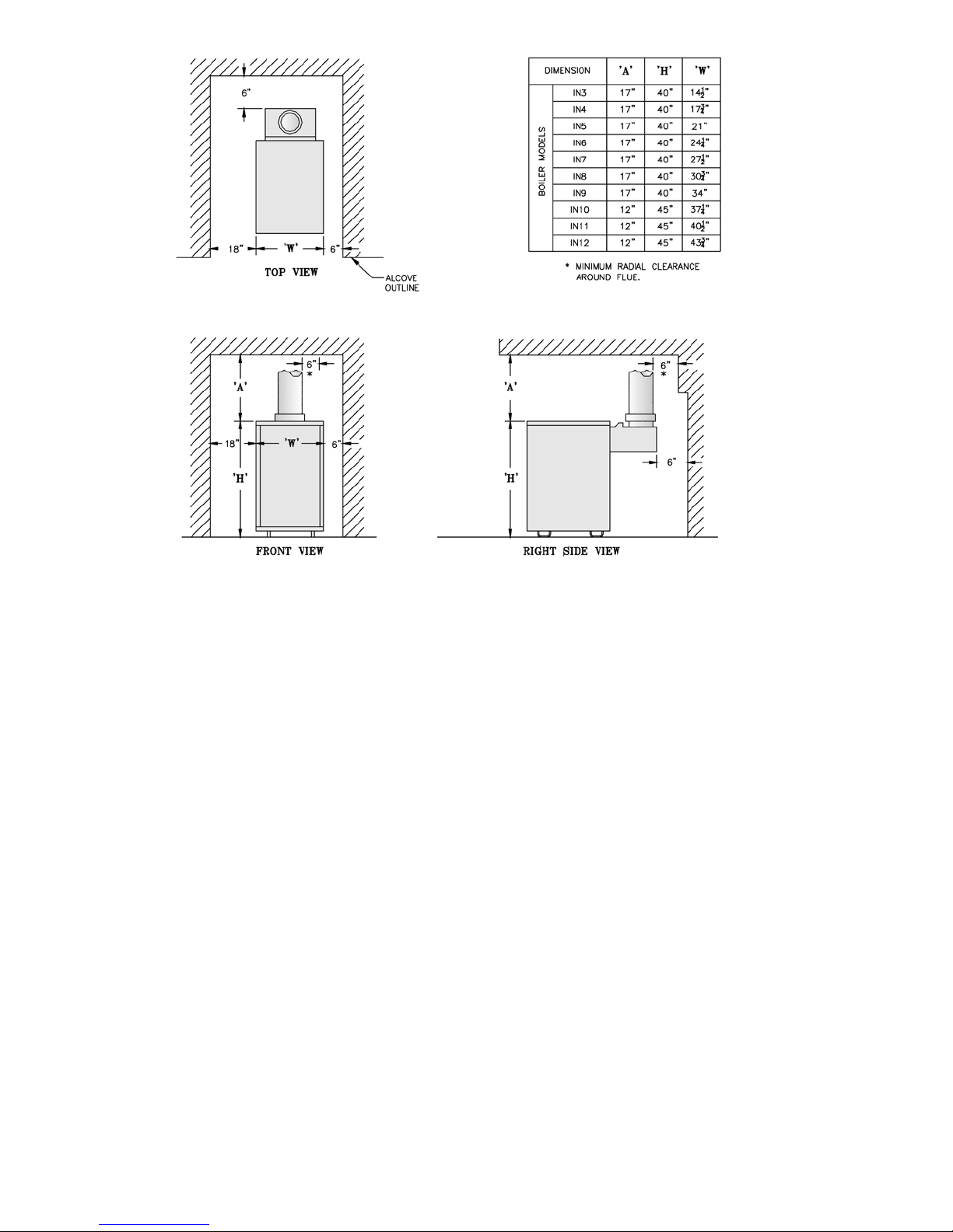
Figure 3: Clearance to Combustible Materials
c. Caulking or sealants applied in joints around
window and door frames, between sole plates
and oors, between wall-ceiling joints, between
wall panels, at plumbing and electrical
penetrations, and at other openings.
5. For boiler located in an unconned space in a
building of other than unusually tight construction,
adequate combustion and ventilation air is normally
provided by fresh air inltration through cracks
around windows and doors.
6. For boiler located within unconned space in
building of unusually tight construction or within
conned space, provide outdoor air through two
permanent openings which communicate directly or
by duct with the outdoors or spaces (crawl or attic)
freely communicating with the outdoors. Locate one
opening within 12 inches of top of space. Locate
remaining opening within 12 inches of bottom of
space. Minimum dimension of air opening is 3
inches. Size each opening per following:
a. Direct communication with outdoors. Minimum
free area of 1 square inch per 4,000 Btu per hour
input of all equipment in space.
b. Vertical ducts. Minimum free area of 1 square
inch per 4,000 Btu per hour input of all
equipment in space. Duct cross-sectional area
shall be same as opening free area.
c. Horizontal ducts. Minimum free area of 1 square
inch per 2,000 Btu per hour input of all
8
equipment in space. Duct cross-sectional area
shall be same as opening free area.
Alternate method for boiler located within conned
space. Use indoor air if two permanent openings
communicate directly with additional space(s) of
sufcient volume such that combined volume of all
spaces meet criteria for unconned space. Size each
opening for minimum free area of 1 square inch per
1,000 Btu per hour input of all equipment in spaces,
but not less than 100 square inches.
7. Ventilation Duct Louvers and Grilles. Equip outside
openings with louvers to prevent entrance of rain
and snow, and screens to prevent entrance of insects
and rodents. Louvers and grilles must be xed in
open position or interlocked with equipment to open
automatically before burner operation. Screens must
not be smaller than ¼ inch mesh.
Consider the blocking effect of louvers, grilles and
screens when calculating the opening size to provide
the required free area. If free area of louver or grille
is not known, assume wood louvers have 20-25
percent free area and metal louvers and grilles have
60-75 percent free area.
H. Do not install boiler where gasoline or other ammable
vapors or liquids, or sources of hydrocarbons (i.e.
bleaches, cleaners, chemicals, sprays, paint removers,
fabric softeners, etc.) are used or stored.
Page 9
II. Knocked-Down Boiler Assembly
GNINRAW
ebdluohsreliobsihtfonoitallatsnI
delliksdnadeniartybylnonekatrednu
.ycnegaecivresdeifilauqamorflennosrep
A. Install Base-Burner-Manifold Assembly
1. Base-Burner-Manifold is shipped assembled from
factory (Gas Valve and Pilot/Burner Assembly is
shipped in the "Gas Controls Carton").
2. Unpack base assembly and place in location where
boiler is to be installed (Refer to Section I: PreInstallation).
B. Install assembled cast iron sections on base assembly:
1. Install (4) 5/16" x ¼" self-tapping screws through
(4) holes in upper base ange with screw heads on
underside of ange. Note: Screws are located in
ber gasket parts bag.
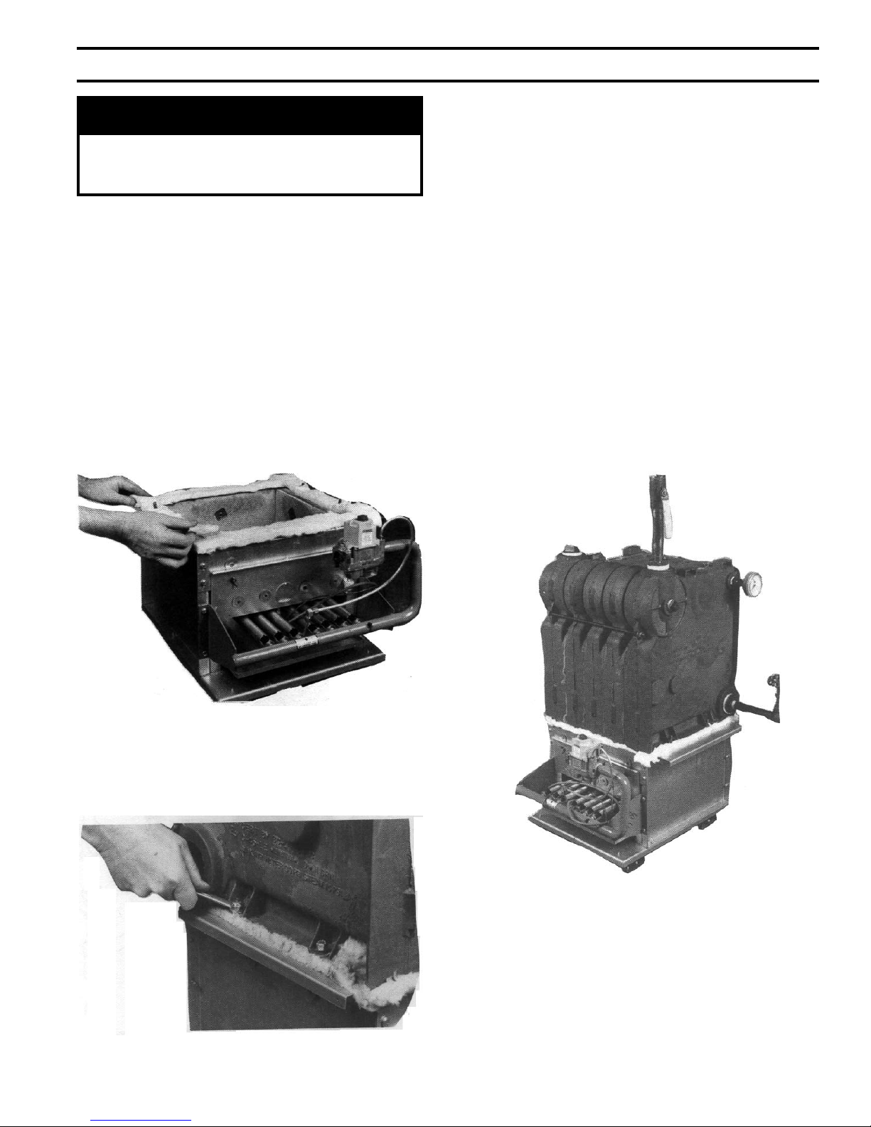
2. Install ceramic ber gasket. See Figure 4.
4. Loosen nuts on tie rods until only nger tight.
5. If Steam boiler or Water boiler less tankless heater,
proceed to Step C.
6. Water Boiler with tankless heater. Remove heater
opening cover plate and install tankless heater as
follows:
a. Place rubber gasket over heater coil and against
heater plate. Align holes in plate and gasket.
b. Install water heater coil through opening into top
nipple ports of boiler and fasten with 3/8" hex
head machine screws and at washers.
Note: If tankless heater is not installed, heater
opening cover plate must remain in place.
C. Test boiler for leaks before connecting to system and
installing controls, trim and jacket.
1. Attach pressure gauge (capable of indicating 30 psi)
on boiler.
2. Attach ll valve and piping to return tapping and
purge valve to supply tapping. See Figure 6.
Figure 4: Base Gasket Installation
3. Position boiler above base with lugs cast in boiler
sections centered over screws protruding from top of
base. Lower boiler onto base taking care not to
disturb ceramic ber gasket. Secure with 5/16"
locknuts and washers provided. See Figure 5.
Figure 5: Section Assembly Attachment
Figure 6: Hydrostatic Pressure Test
3. Install plugs in remaining tappings.
4. Fill boiler completely with water by venting air
through purge valve. Close purge valve and apply
water pressure of at least 10 psi but not exceeding
30 psi gauge pressure.
5. Examine boiler carefully inside and outside for leaks
or damage due to shipment or handling.
9
Page 10
D. Install Canopy.
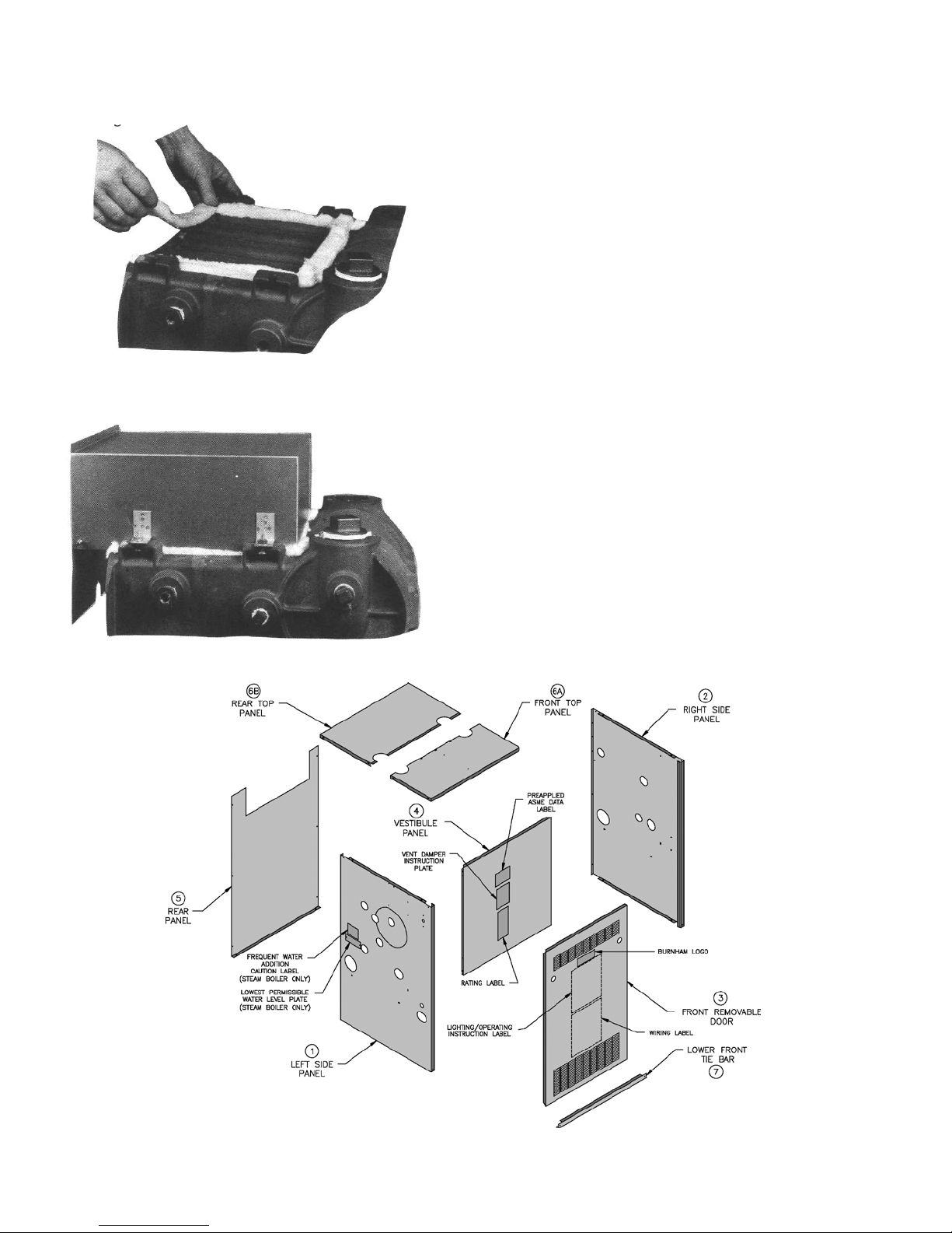
1. Install ½" thick x 1" wide ceramic ber gasket. See
Figure 7.
Figure 7: Canopy Gasket Installation
2. Position canopy on ceramic ber gasket. See Figure
8.
3. Attach canopy using ¼" carriage bolts, nuts, and
washers provided.
E. Inspect joints between sections. They were factory
sealed. If there are any openings due to shipment or
handling, reseal with boiler putty.
F. Install Jacket. See Figure 9.
1. Models IN7-IN12 steam boilers: remove 3 inch
diameter knockouts in jacket top panels.
2. Raise rear panel under rear ange of canopy and rest
on oor. Position rear panel and secure to jacket side
panels with sheet metal screws. For Models IN10IN12, secure jacket upper rear panels to side panels
with sheet metal screws.
3. Secure both jacket side panels to base with sheet
metal screws.
4. Position front tie bar and secure to jacket side panels
with sheet metal screws.
5. Position vestibule panel and secure to side panels
with sheet metal screws.
6. Attach Rating Label and Vent Damper Instruction
Label at designated locations on vestibule panel.
7. Install top panels by placing over and around outside
of side and rear panels. Seat fully and secure with
sheet metal screws.
8. Install black plastic rings into 1-3/32 inch diameter
holes located below upper louvers of front
removable door.
Figure 8: Canopy Installation
10
Figure 9: Jacket Assembly
Page 11
9. Install front removable door by engaging upper side
edges of panel with side receiving anges, sliding
up and under top panel ange - seating front door
fully - then sliding down to engage bottom ange
behind lower front tie bar.
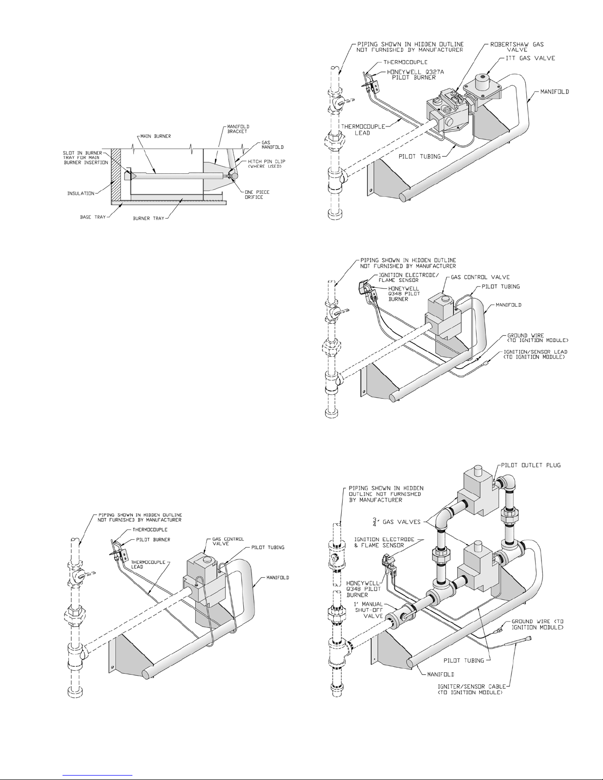
G. Install Pilot/Burner Assembly (shipped in Gas
Controls Carton). See Figure 10.
Figure 10: Combustion Chamber
1. Remove jacket front removable door.
a. Remove burner access panel located above
burners.
b. Install Pilot/Burner Assembly where noted on
gas manifold.
i. Insert rear of burner in burner tray slot.
ii. Position burner over the orice.
NOTE: The burner to the right may need to
be lifted from the orice to install pilot/
burner assembly. Reinstall lifted burner
over the orice.
c. Reinstall burner access panel.
H. Install Gas Valve on main gas burner assembly (if not
factory assembled). See Figure 11, 12, 13, 14 or 15.
1. Connect gas valve to manifold.
2. Connect pilot tubing from pilot burner to gas valve
pilot tapping.
3. Continuous Ignition (standing pilot): connect
thermocouple to gas valve.
Figure 12: Pilot and Gas Piping, Continuous
Ignition (Standing Pilot) (IN10 through IN12 Only)
Figure 13: Pilot and Gas Piping, Intermittent
Ignition (EI) (IN3 through IN11 Only)
Figure 11: Pilot and Gas Piping, Continuous
Ignition (Standing Pilot) (IN3 through IN9 Only)
Figure 14: Pilot and Gas Piping, Intermittent
Ignition (EI) (IN12 Only)
11
Page 12

Figure 15: Pilot and Gas Piping, Intermittent
Ignition (HSP) (IN3 Through IN9)
I. Install Blocked Vent Switch with sheet metal screws.
1. Models IN3 - IN9. Install on rear ange of canopy.
See Figure 16.
2. Models IN10 - IN12. Install on right side of draft
hood. See Figure 17. Reset switch must face away
from draft hood relief opening.
Figure 17: Blocked Vent Switch Installation,
IN10 through IN12
3. Attach black 18-2 harness to Blocked Vent Switch
terminals. Use end with two fully insulated
disconnects.
4. Secure harness to right side jacket panel with clamp.
5. Insert harness through ¾ inch hole in right side
jacket panel. Secure with strain relief bushing
Figure 16: Blocked Vent Switch Installation,
IN3 through IN9
J. Intermittent Ignition (EI): Install Ignition Module.
1. Mount ignition module mounting bracket to inside
of right side panel using (2) #6 x ¾" sheet metal
screws provided.
2. Mount ignition module to bracket using (2) #8 x ½"
sheet metal screws provided.
3. Install (3) wire harness from ignition module to gas
valve as shown in wiring diagrams.
K. Continue to Section III: Semi-Pak Boiler Assembly,
Step C.
12
Page 13
III. Semi-Pak Boiler Assembly
GNINRAW
ebdluohsreliobsihtfonoitallatsnI
delliksdnadeniartybylnonekatrednu
.ycnegaecivresdeifilauqamorflennosrep
ECITON
aniyrucremniatnocstimiLerusserPA404L
oD.ebutdelaes ton hsartehtnitimilecalp
.efillufesustifodneehtta
sniatnoctahttimilagnicalpersitimilsihtfI
od,ebutdelaesaniyrucrem ton ruoyecalp
.hsartehtnitimildlo
tnemeganametsawlacolruoytcatnoC
gnidragersnoitcurtsnirofytirohtua
sihtfolasopsidreporpehtdnagnilcycer
niyrucremgniniatnoctimildlonaforo,timil
.ebutdelaesa
ta.cnIllewyenoHllac,snoitseuqevahuoyfI
.2051-864-008-1
A. Remove Crate
1. Remove all hold down screws and brackets.
2. Slide boiler to rear of skid and carefully remove
from crate skid onto 2 inch thick piece of wood and
then onto oor. Do not bump boiler jacket against
oor.
3. Do not drop boiler at any time.
B. Move Boiler To Permanent Position. Refer to Section
I: Pre-Installation.
C. Identify Trim and Controls
FIRST - Determine controls ordered with boiler and
refer to appropriate section(s) following:
There are two ordering methods for trim and controls:
l. EZ–Connect Carton (either steam or water) includes
trim, controls, wiring and wiring instructions for
installation.
2. Separate Trim Carton (steam or water) and Control
Carton (steam or water). Only wiring requiring
special connections is provided. For wiring
requirements, refer to Section VIII: Electrical and
appropriate wiring diagram.
D. Install Trim and Controls
Refer to appropriate paragraphs (following) for trim
and controls to be installed.
1. Steam Boiler with Probe Low Water Cutoff
a. Install pressure limit control into Tapping "H"
with siphon, ¾" x ¼" hex bushing, ¾" elbow and
¾" x 3" nipple provided. See Figures 1 and 2.
DO NOT TWIST CONTROL. Use wrench on
hex tting located at bottom of control. See
Figure 18A or 18B.
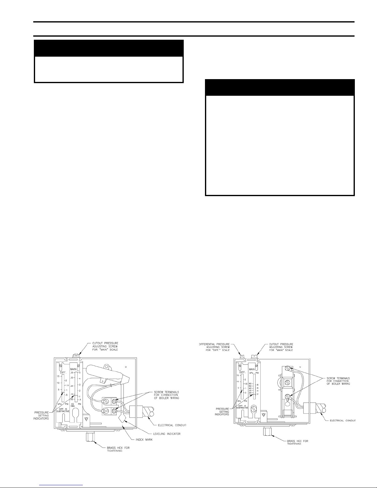
b. Level the L404A pressure limit by carefully
bending the syphon until the limit's leveling
indicator hangs freely with its pointer directly
over the index mark inside the back of the case.
See Figure 18A.
c. The L404F pressure limit employs a snap action
switch and does not require leveling. See Figure
18B.
d. Install pressure gauge into Tapping "B" (½ NPT
bushed to ¼ NPT). See Figures 1 and 2. Tighten
with wrench applied to square shank on back of
gauge. DO NOT APPLY PRESSURE ON
GAUGE CASE since this may destroy
calibration of gauge.
e. Install Low Water Cutoff Probe into Tapping "K"
(¾ NPT). HANDLE PROBE WITH CARE.
f. Attach Low Water cutoff Control to Probe by
following instructions packed with control.
g. Install gauge glass ttings into Tappings "C"
(½ NPT). See Figures 1 and 2. Lower tting has
small drain valve.
Figure 18A: L404A Pressure Limit Control
Figure 18B: L404F Pressure Limit Control
13
Page 14
h. Install gauge glass and protective rods in ttings.
i. Attach "Lowest Permissible Water Level" Plate
with sheet metal screws in location indicated in
Figure 9.
j. Attach "Frequent Water Addition" Label above
the "Lowest Permissible Water Level" Plate.
2. Steam Boiler with McDonnell & Miller 67 Float
Low Water Cutoff
a. Install Low Water Cutoff, see instructions packed
with control.
i. Screw brass nipples with union halves into
Tappings "C" (½ NPT). See Figure 1 and 2.
ii. Attach Gauge Glass/Low Water Cutoff
Assembly to union halves.
iii. Afx Blow-Down Card to Jacket Left Side
Panel adjacent to low water cutoff.
iv. Provide blow down discharge piping.
b. Attach street elbow siphon and pressure limit
control to low water cutoff. DO NOT TWIST
CONTROL. Use wrench on hex tting located at
bottom of control.
c. Level the L404A pressure limit by carefully
bending the syphon until the limit's levelling
indicator hangs freely with its pointer directly
over the index mark inside the back of the case.
See Figure 18A.
d. The L404F pressure limit employs a snap action
switch and does not require leveling. See Figure
18B.
e. Install pressure gauge into Tapping "H" (¾ NPT
bushed to ¼ NPT). See Figures 1 and 2. Tighten
with wrench applied to square shank on back of
gauge. DO NOT APPLY PRESSURE ON
GAUGE CASE since this may destroy
calibration of gauge.
f. Attach "Lowest Permissible Water Level" Plate
with sheet metal screws in location indicated in
Figure 9.
g. Attach "Frequent Water Addition" Label above
the "Lowest Permissible Water Level" Plate.
3. All Steam Boilers and Water Boilers except
"EZW" and "WC" Controls Cartons
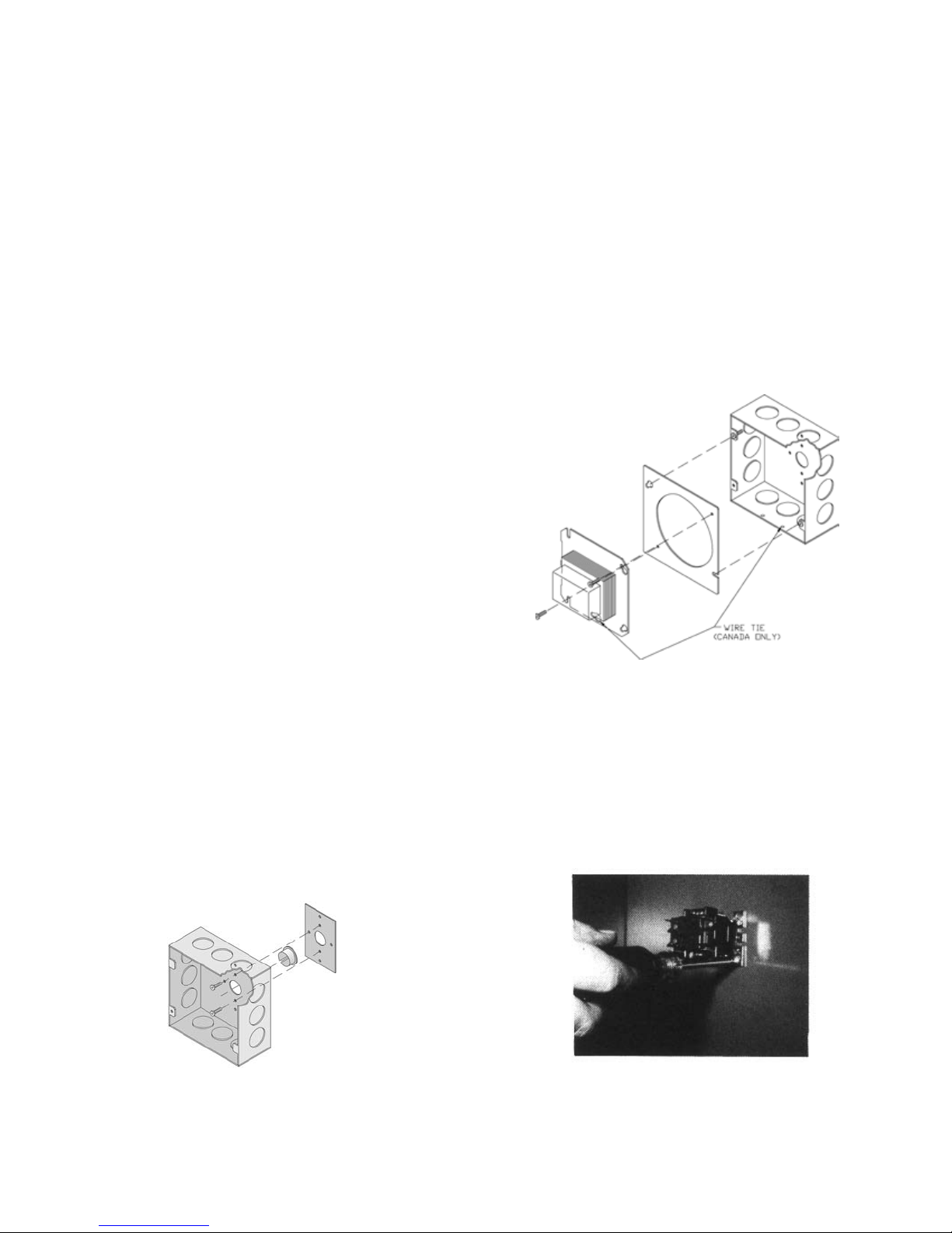
a. Install Junction Box. See Figure 19A.
i. Remove center knockout in rear of Junction
Box and insert black plastic snap bushing in
hole.
ii. Install mounting bracket to rear of Junction
Box with two (2) blunt sheet metal screws
provided.
iii. Align center and mounting holes of Junction
Box with upper front corner of jacket left
side panel.
iv. Install Junction Box to jacket from inside
vestibule area with two (2) blunt sheet metal
screws provided.
b. Mount transformer on Junction Box. For
Canadian boiler provide strain relief by loosely
securing Transformer to Junction Box with wire
tie inserted through Transformer plate and a
Junction Box mounting hole. See Figure 19B.
Figure 19B: Junction Box and Transformer
Assembly
c. Fork connector on yellow and blue (HSP only)
wire(s) of gas valve harness must be removed
and wire stripped before making wire
connections. Refer to Section VIII for wiring.
d. Steam Boilers only. Secure the R8222
Thermostat Isolation Relay to upper left corner of
jacket vestibule panel with sheet metal screws
provided. See Figure 20.
Figure 19A: Junction Box and Mounting Bracket
Assembly
14
Figure 20: Thermostat Isolation Relay Attachment
Page 15

e. Water with tankless heater only (EZWT and
WCT). Secure R8225D relay to Junction Box.
See Figure 1.
Water Boiler
4.
a. Install Temperature/Pressure Gauge into upper
Tapping "C" (½ NPT bushed to ¼ NPT). See
Figure 1 and 2. Tighten by wrench applied to
square shank on back of gauge. DO NOT
APPLY PRESSURE ON GAUGE CASE since
this may destroy calibration of gauge.
b. Install hot water temperature limit and/or
combination control. Remove well from control.
Screw well into Tapping "H" (¾ NPT). See
Figure 1 and 2. Install bulb in well as far as
possible, then tighten set screw.
c. On boilers equipped with a circulator without
tankless heater in areas where condensation of
ue gases is encountered in boiler ueways, a
reverse-acting circulator control should be
installed in supply as close as possible to boiler
in order to avoid condensation.
E. Continue to Section IV. Packaged Boiler Assembly,
Paragraph E.
15
Page 16
IV. Packaged Boiler Assembly
GNINRAW
ebdluohsreliobsihtfonoitallatsnI
delliksdnadeniartybylnonekatrednu
.ycnegaecivresdeifilauqamorflennosrep
GNINRAW
ynaecalprodoohtfardreliobretlatonoD
ehtnirepmaddevorppa-nonronoitcurtsbo
egallipssageulF.metsystnevrognihceerb
lliwnoitacifitrecCLTE/LTE.rucconac
.diovemoceb
A. Remove crate and move boiler to permanent position
as detailed in Section III: Semi-Pak Boiler Assembly.
B. Remove Jacket Front Panel. See Figure 50.
C. Remove poly bag from vestibule area.
D. On Steam Boilers with probe low water cutoff the
L404 pressure limit/control has been packed in the
vestibule area.
1. Screw the pressure limit/control onto the syphon.
DO NOT TWIST CONTROL. Use wrench on hex
tting at bottom of control. See Figures 18A or
18B.
2. Snap the electrical conduit from the adjacent
junction box into the hole in the control.
3. Open the control's clear cover and attach the two (2)
wires in the conduit to the two (2) unused screw
terminals.
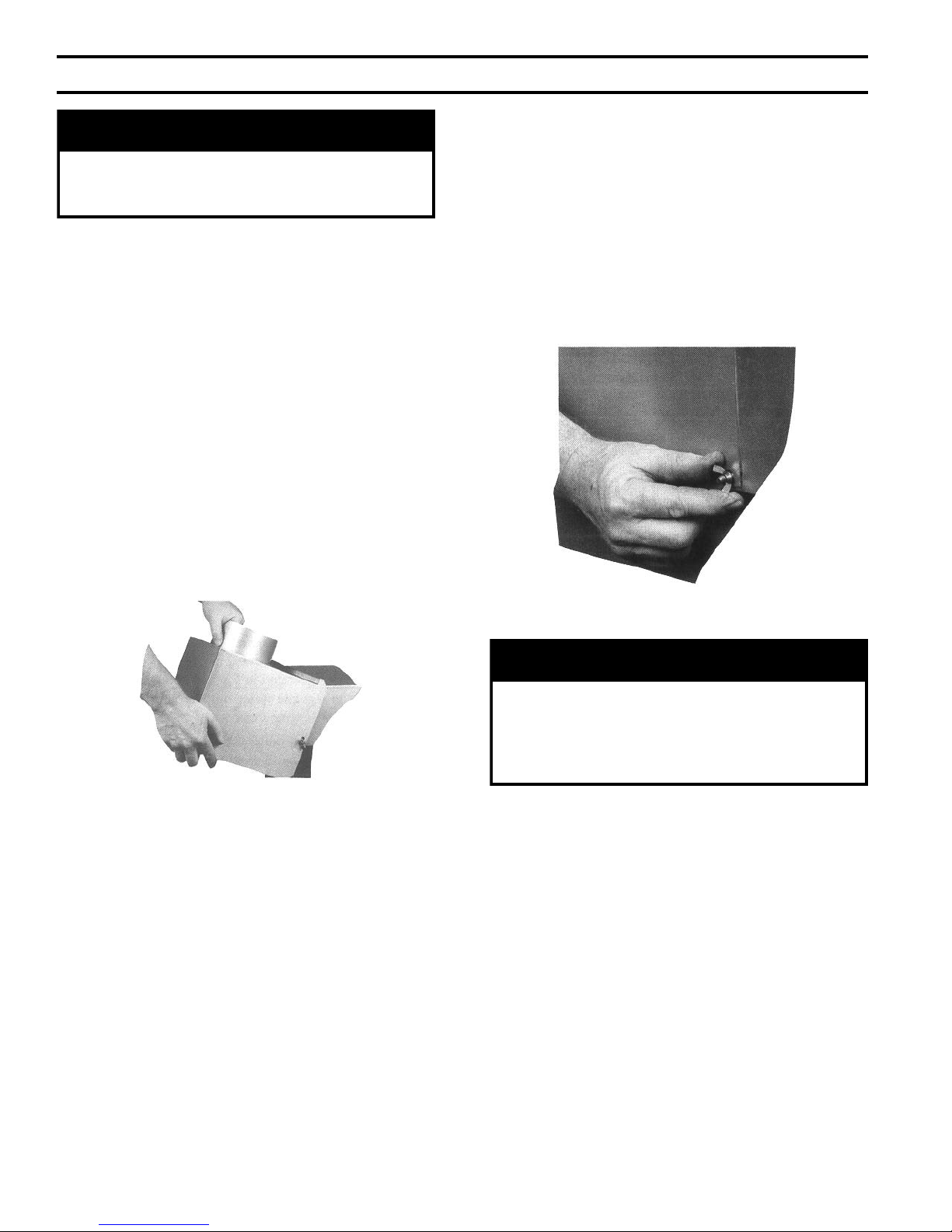
E. Install Jacket Front Panel.
F. Install Draft Hood. Models IN3 through IN9.
1. Locate and open "Rear Draft Hood Carton".
2. Position Draft Hood on Canopy Rear Flange. See
Figure 21. Top canopy ange must fully engage
"U"-shaped draft hood ange for proper installation
and operation. Care must be taken to assure that
draft hood is level.
3. Secure Rear Draft Hood to Canopy with wing nuts
provided. See Figure 22.
Figure 21: Draft Hood Attachment
Figure 22: Securing Draft Hood to Canopy
16
Page 17
V. Piping and Trim
GNINRAW
tsumgnipipegrahcsidevlav)feiler(ytefaS
erevesfolaitnetopehttahthcusdepipeb
ynaniepipTONOD.detanimilesisnrub
TONOD.ruccodluocgnizeerferehwaera
.spacrosgulp,sevlavffo-tuhsynallatsni
egrahcsidreporprofsedoClacoLtlusnoC
.tnemegnarragnipip
GNINRAW
roreliobotegamaddnanoitareporeporpminitluseryamreliobepipylreporpoteruliaF
.erutcurts
ECITON
hserfnieiT.tluserlliwnoisorrocreliobdetareleccA.sreliobmaetsniretawdenetfosesutonoD
.renetfosretawafomaertspureliobehtotylppusretaw
dna,stnenopmocreliobleetsdnanorifonoisorrocesuaclliwretawreliobfonoitanimatnocnegyxO
negyxoybdesuacsmelborprevoctonseodytnarraWdradnatSs'mahnruB.eruliafreliobotdaelnac
.retawfonoitiddatneuqerfybdesuacpu-dliub)emil(elacsroretawreliobfonoitanimatnoc
:gnipipreppocfoscitsiretcarahcgniwollofehtredisnoc,gnipipmaetsrofreppocgnisuerofeB
)1 esuacdnasessertslacinahcemecudninacnoisnapxelamrehtfotneiciffeochgih
,noitallatsnidnangisedmetsysgnipipehtnirofdetnuoccatonfisesionnoitcartnoc/noisnapxe
)2 ehtnidedulcniebtsumgnipipreppocdetalusninufo)ssoltaeh(etarrefsnarttaehhgih
,reliobehtezisotdesusrotcafpukcipdnagnipiplamron
)3 ,refsnarttaehroopesuacnacmetsysehtnipudnetahtsexulfdnasetsapgnizarbrogniredlos
tuoliobehtgniruddevomerylhguorohttonfimaetstewdnaenilretawydaetsnuna,gnigrus
,dnaerudecorp
)4 retawniatrecnislatemralimissidoteudruccoyamlatemgniniojdaehtfonoisorroccinavlag
.desutonerasnoinucirtceleidfiseirtsimehc
A. Design and install boiler and system piping to prevent
oxygen contamination of boiler water. Sources of
oxygen contamination are system leaks requiring
addition of makeup water, ttings, and oxygen
permeable materials in distribution system. Eliminate
oxygen contamination by repairing system leaks,
repairing ttings, using nonpermeable materials in
distribution system, and eliminating open tanks in
system, or isolating boiler from system with heat
exchanger.
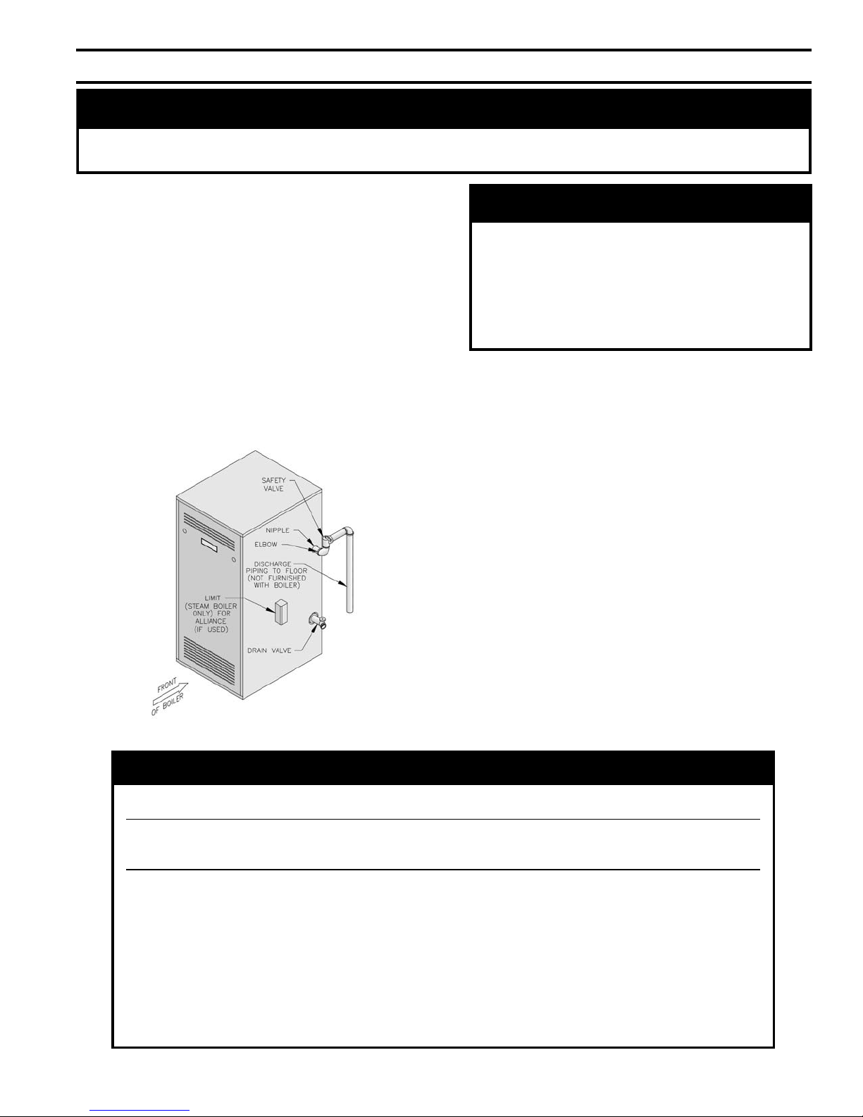
B. Install Safety (Relief) Valve in Tapping "E" (¾ NPT).
See Figure 23. Use ¾ NPT x 3" nipple and ¾ NPT
elbow provided. Safety (Relief) Valve must be installed
with spindle in vertical position.
Figure 23: Trim Installation
C. Install Drain Valve in Tapping "F" (2 NPT bushed to
¾ NPT). See Figure 23.
D. Connect supply and return piping to heating system.
Maintain minimum ½ inch clearance from combustible
materials.
1. For STEAM HEATING see Figure 24. Consult
I=B=R Installation and Piping Guides.
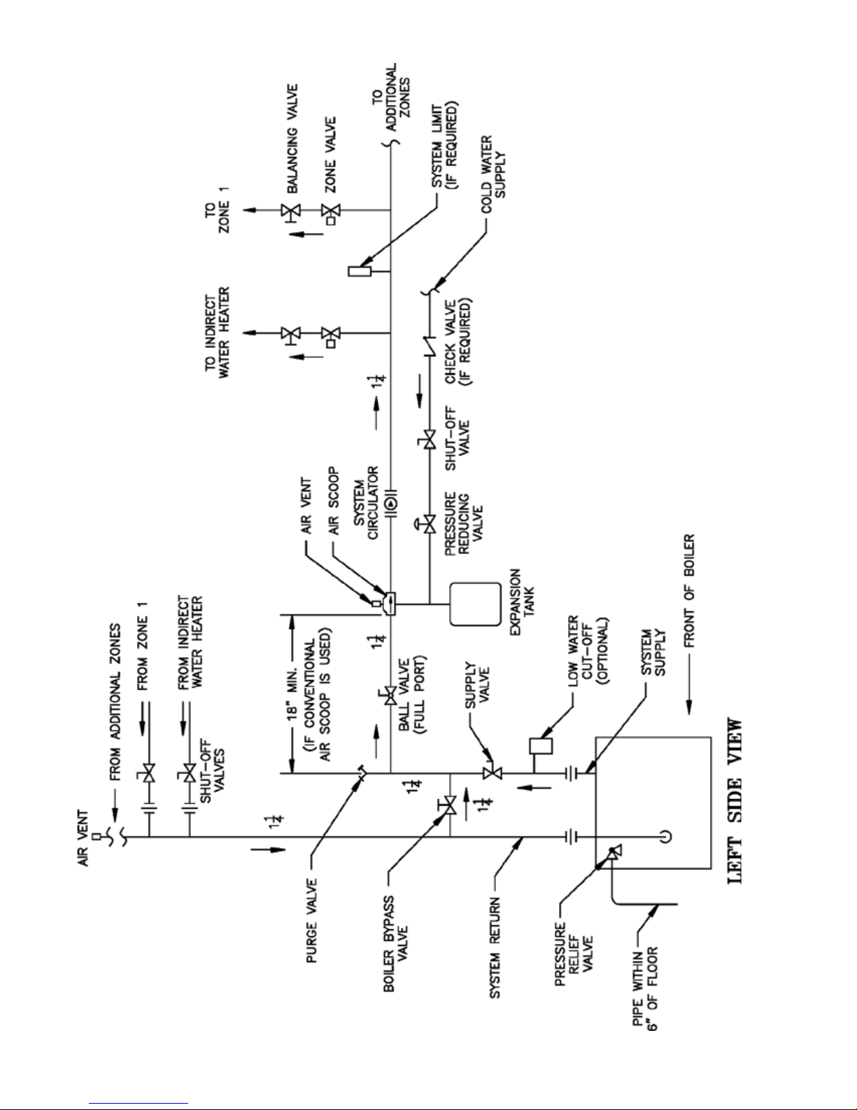
2. For HOT WATER HEATING with Circulator
(forced) see Figure 25 and 25A. Consult I=B=R
Installation and Piping Guides.
3. If boiler is used in connection with refrigeration
systems, boiler must be installed with chilled
medium piped in parallel with heating boiler using
appropriate valves to prevent the chilled medium
from entering the boiler. See Figure 26. Also
consult I=B=R Installation and Piping Guides.
4. If boiler is connected to heating coils located in air
handling units where they may be exposed to
refrigerated air, boiler piping must be equipped with
ow control valves to prevent gravity circulation of
boiler water during cooling system operation.
17
Page 18
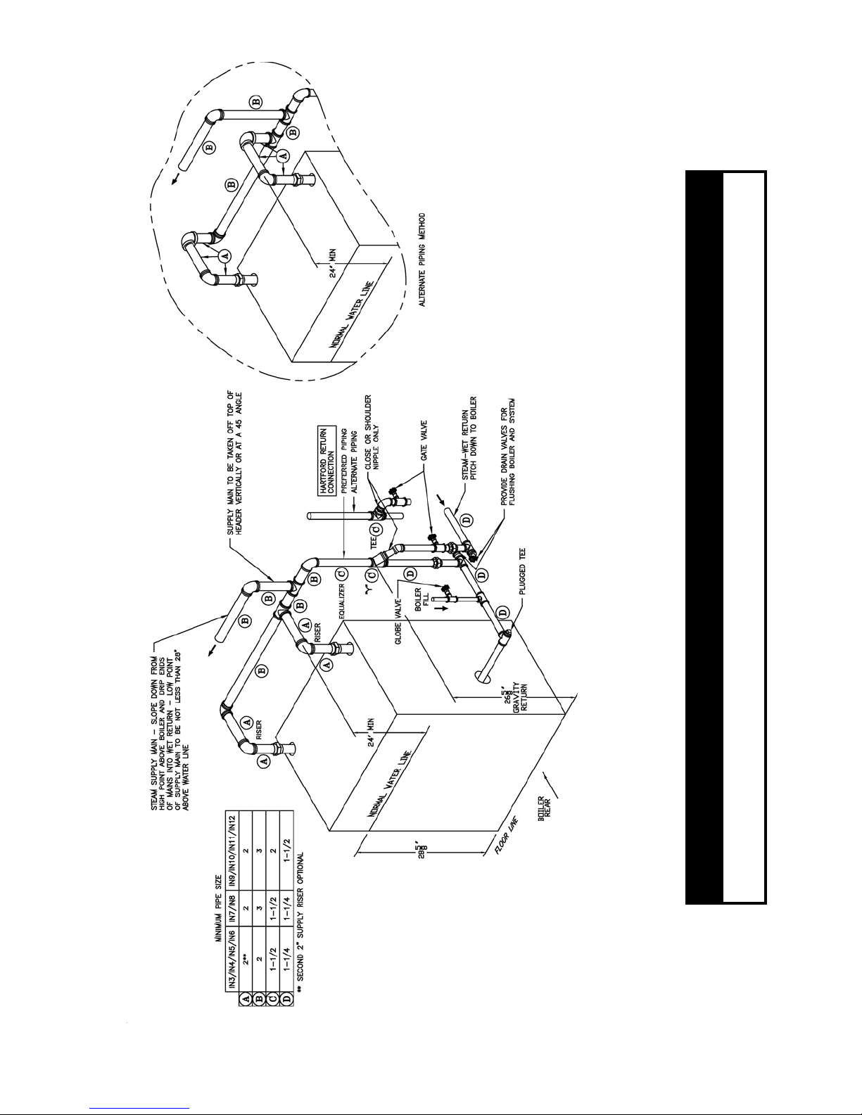
ECITON
enilretaw,esionmetsysevissecxenitluseryamlaunamsihtnideificepssareliobepipoteruliaF
.revoyrracretawdnasnoitautculf
Figure 24: Steam Boiler Piping (Minimum)
18
Page 19
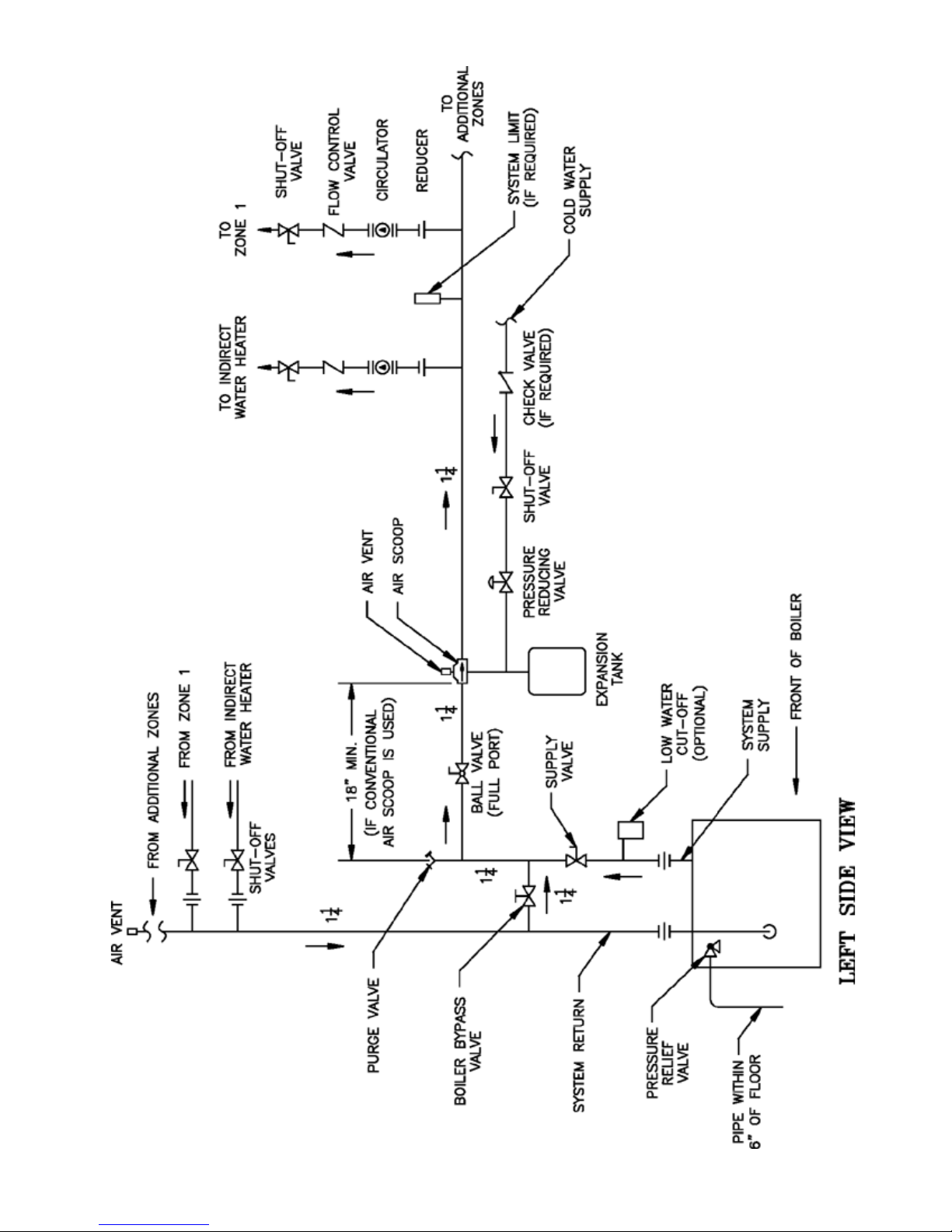
Figure 25: Recommended Water Piping for Circulator Zoned Heating System
19
Page 20
20
Figure 25A: Recommended Water Piping for Zone Valve Zoned Heating System
Page 21
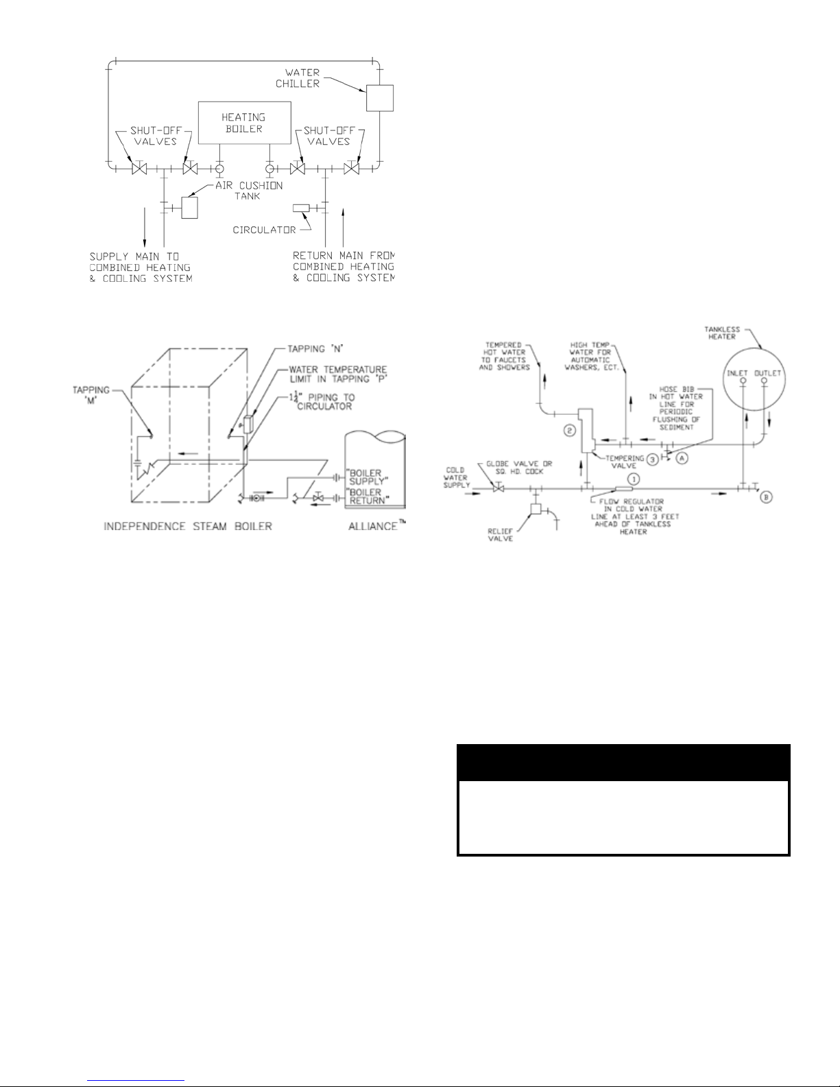
Figure 26: Recommended Piping for Combination
GNINRAW
sselknattaevlavgniximcitamotuallatsnI
rosnrubfoksirdiovaotteltuoretaeh
taretawtohylevissecxeoteudgnidlacs
.serutxif
Heating and Cooling (Refrigeration) Systems
E. Alliance Indirect Water Heater (if used). Refer to
Alliance Installation, Operating and Service Instructions
for additional information.
1. Steam. See Figure 27 for piping recommendations.
a. Supply and Return Piping. Connect supply
piping to Tapping "N" (1¼ NPT) and return
piping to Tapping "M" (1¼ NPT). Install zone
circulator and strainer in supply piping. Install
check valve to prevent gravity circulation of
boiler water.
b. Limit. See Figure 23. Install temperature limit
control (Honeywell L4006A or equal) in Tapping
"P" (¾ NPT). See Figure 2. Set at 180°F to
prevent steam production during non-space
heating periods.
Figure 27: Recommended Piping for
Indirect Water Heater
5. Use boiler bypass if boiler is operated in system
which has a large volume or excessive radiation
where low boiler water temperatures may be
encountered (i.e. converted gravity circulation
system, etc.).
a. Bypass should be same size as supply and return
lines with valves located in bypass and supply
outlet as illustrated in Figures 25 and 25A in
order to regulate water ow to maintain higher
boiler water temperatures.
b. Set bypass and boiler supply valves to a half
throttle position to start.
c. After installation is complete, operate boiler
according to Section IX: System Start-up.
6. A hot water boiler installed above radiation level
must be provided with a low water cutoff device as
part of installation.
The low water cut off must be mounted in the
system piping above the boiler. The minimum safe
water level of a hot water boiler is just above the
highest water containing cavity of the boiler; that is,
a hot water boiler must be full of water to operate
safely (see XII. Appendix for further details) .
7. If a tankless heater coil is used, connect water lines
to ¾ NPT tappings in coil plate.
Figure 28: Tankless Heater Piping
2. Water without tankless heater. Install in same
manner as space heating zone.
F. Tankless Heater (if used). See Figure 28.
1. Install automatic tempering or mixing valve to
prevent delivery of scalding hot water to xtures.
Higher temperature water for dishwashers and
automatic washers is possible by piping hot water
from heater prior to entering mixing valve. Install
per manufacturer's instructions.
2. Install ow regulator. Match regulator rating to
tankless heater rating. Install in cold water inlet
below and minimum 3 feet downstream of tankless
heater inlet.
3. Install water softener in areas of hard water, this will
reduce mineral deposits which could hinder heat
transfer and delivery of hot water.
21
Page 22

G. If a long term pressure test of the hydronic system is
required, the boiler should rst be isolated to avoid a
pressure loss due to the escape of air trapped in the
boiler.
To perform a long term pressure test including the
boiler, ALL trapped air must rst be removed from the
boiler.
A loss of pressure during such a test, with no visible
water leakage, is an indication that the boiler contained
trapped air.
22
Page 23
VI. Gas Piping
GNINRAW
otylppussagepipylreporpoteruliaF
dnanoitareporeporpminitluseryamreliob
syawlA.erutcurtsroreliobehtotegamad
eerfkaelyletulosbasignipipsagerussa
ehtrofepytdnaezisreporpehtfodna
.daoldetcennoc
yamrotalugererusserpsaglanoitiddanA
.reilppussagtlusnoC.dedeeneb
GNINRAW
nosdnuopmocdaerhtreporpesuoteruliaF
foskaelnitluseryamsrotcennocsaglla
.sagelbammalf
GNINRAW
ebtsummetsysdnareliobotylppussaG
rognillatsniotroirpffotuhsyletulosba
.gnipipsagreliobgnicivres
relioB
ledoM
rebmuN
yticapaCdetaR
]ruohrepteefcibuc[
saG
noitcennoC
eziS
larutaN enaporP/PL
3NI 26 ¾42 ½
4NI 501 24 ½
5NI 041 65 ½
6NI 571 07 ½
7NI 012 48 ¾
8NI 542 89 ¾
9NI 082 211 ¾
01NI 513 621 *¾
11NI 943 ½931 *¾
21NI 583 451 1
11NIdna01NIno"1siezisnoitcennocsaG*
)toliPgnidnatS(noitingIsuounitnoC
A. Size gas Piping. Design system to provide
adequate gas supply to boiler. Consider these factors:
1. Allowable pressure drop from point of delivery to
boiler. Maximum allowable system pressure is ½
psig. Actual point of delivery pressure may be less;
contact gas supplier for additional information.
Minimum gas valve inlet pressure is indicated on
Rating Label, located on the vestibule panel.
2. Maximum gas demand. Table 2 lists boiler input
rate. Also consider existing and expected future gas
utilization equipment (i.e. water heater, cooking
equipment).
Table 2: Rated Input
jurisdiction species a gravity factor be applied. For
specic gravity greater than 0.70, apply gravity
factor from Table 5. If exact specic gravity is not
shown choose next higher value.
For materials or conditions other than those listed
above, refer to the National Fuel Gas Code, NFPA
54/ANSI Z223.1 and/or CAN/CGA B149
Installation Codes, or size system using standard
engineering methods acceptable to authority having
jurisdiction.
B. Connect boiler gas valve to gas supply system.
1. Use methods and materials in accordance with local
plumbing codes and requirements of gas supplier. In
absence of such requirements, follow the National
Fuel Gas Code, NFPA 54/ANSI Z223.1 and/or
CAN/CGA B149 Installation Codes.
2. Use thread (joint) compounds (pipe dope) resistant
to action of liqueed petroleum gas.
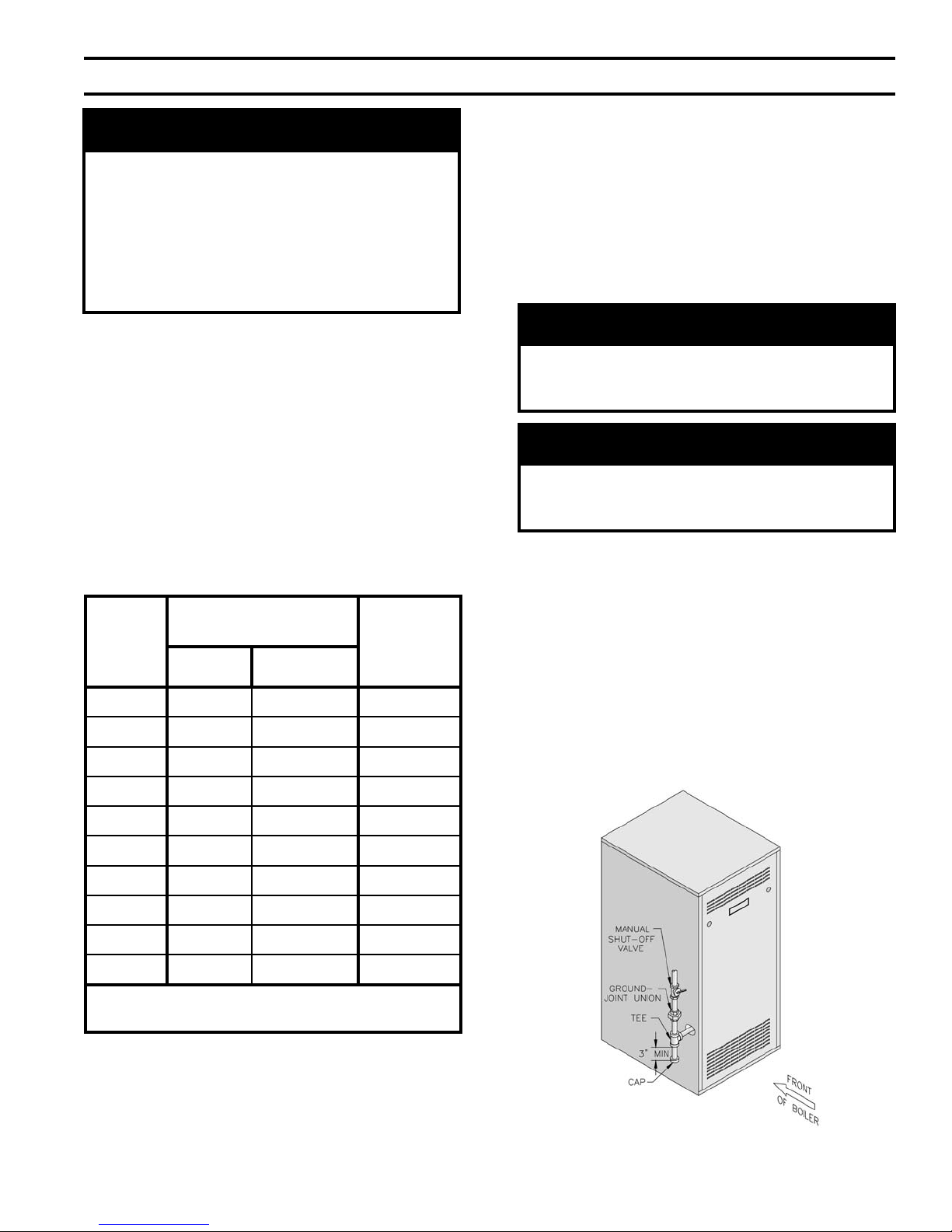
3. Install sediment trap, ground-joint union and manual
shut-off valve upstream of boiler gas valve and
outside jacket. See Figure 29.
3. Length of piping and number of ttings. Refer to
Table 3 for maximum capacity of Schedule 40 pipe.
Table 4 lists equivalent length for standard ttings.
4. Specic gravity of gas. Gas piping systems for gas
with a specic gravity of 0.70 or less can be sized
directly from Table 3, unless authority having
Figure 29: Recommended Gas Piping
23
Page 24
4. All above ground gas piping upstream from manual
REGNAD
semalfnepo,seldnac,sehctamesutonoD
.skaelrofkcehcotecruosnoitingirehtoro
ECITON
neebevahlevelaesevobateef000,2nahtretaergsedutitlatanoitallatsniroftliubsreliobASU
ehtreplevelaesevobateef000,1reptnecrep4etartupnisagecuderotdecifiroyllaiceps
'sreliobnaidanaC.FxidneppAdna2.1.8noitceS,1.322ZISNA/45APFN,edoCsaGleuFlanoitaN
ehtybelbaifitnedierasledomreliobedutitlahgiH.lebalgnitarehtnodetacidnisignizisecifiro
:lebalgnitarehtnoxiffusrebmunledomehtnitigiddriht
noitavele.tf0002nahtssel2__-___NI_
)adanaC(noitavele.tf0054ot00024__-___NI_
)ASU(noitavele.tf0005ot00025__-___NI_
htgneL
]teeF[
porDerusserP.c.whcni3.0 porDerusserP.c.whcni5.0
½ ¾ 1 ¼1 ½ ¾ 1 ¼1
01 231 872 025 050,1 571 063 086 004,1
02 29 091 053 037 021 052 564 059
03 37 251 582 095 79 002 573 077
04 36 031 542 005 28 071 023 066
05 65 511 512 044 37 151 582 085
06 05 501 591 004 66 831 062 035
07 64 69 081 073 16 521 042 094
08 34 09 071 053 75 811 022 064
09 04 48 061 023 35 011 502 034
001 83 97 051 503 05 301 591 004
gnittiF
eziSepiPlanimoN
½ ¾ 1 ¼1
llE°54 7.0 1 2.1 6.1
llE°09 6.1 1.2 6.2 5.3
sA(eeT
)woblE
1.3 1.4 2.5 9.6
cificepS
ytivarG
noitcerroC
rotcaF
cificepS
ytivarG
noitcerroC
rotcaF
05.0 01.1 03.1 70.1
55.0 40.1 04.1 40.1
06.0 00.1 05.1 00.1
56.0 69.0 06.1 79.0
07.0 39.0 07.1 49.0
57.0 09.0
08.0 78.0
gas valve must be electrically continuous and
bonded to a grounding electrode. Do not use gas
piping as a grounding electrode. Refer to the
National Electrical Code, ANSI/NFPA 70 and/or
CSA C22.1 Electrical Code.
C. Pressure Test. The boiler and its gas connection must
½ psig or less, isolate boiler from gas supply piping
by closing boiler's individual manual shut-off valve.
2. Using soap solution, or similar non-combustible
solution, electronic leak detector or other approved
method. Check that boiler gas piping valves, and all
other components are leak free. Eliminate any
leaks.
be leak tested before placing boiler in operation.
1. Protect boiler gas valve. For all testing over ½ psig,
boiler an its individual shut-off valve must be
disconnected from gas supply piping. For testing at
Table 3: Maximum Capacity of Schedule 40 Pipe in CFH for Gas Pressures of 0.5 psig or Less
Table 4: Fitting Equivalent Lengths
24
Table 5: Specic Gravity Correction Factors
Page 25
VII. Venting
REGNAD
gnillatsnierofebyenmihcgnitsixetcepsnI
detarofrepecalperronaelcoteruliaF.reliob
royrujnierevesesuaclliwgninilelitroepip
.htaed
GNINRAW
eraerehtosdellatsniebtsumdnanoitarepoefasrofriahserfsdeenecnailppasihT
.rianoitalitnevdnanoitsubmocetauqedarofsnoisivorp
-erPehtnideniatnocsnoitcirtsernoitcurtsnirianoitsubmocwollofdnadnatsrednu,daeR
.launamsihtfosnoitcurtsninoitallatsnI
fosecruosro,sdiuqilrosropavelbammalfrehtoroenilosagerehwecnailppaetarepotonoD
,srenetfoscirbaf,srevomertniap,syarps,slacimehc,srenaelc,sehcaelb.e.i(snobracordyh
.riaehtnitneserpro/dnaderots,desuera).cte
NOITUAC
lortnocotrepmadtnevenoesutonoD
.secnailppagnitaehowt
rofecnaraelcetauqedaedivorP
ecnaraelcmuminim"6-gnicivres
elbitsubmocdnarepmadneewteb
.noitcurtsnoc
ECITON
ehtrevorepmadtnevehtecrofTONOD
.rallocdoohtfardehtnodaebdellor
ehtnotserdluohsrepmadtnevehT
.daebdellor
,snoitacificepsehtotreferesaelP
elbuortdnasnoitcurtsninoitallatsni
tnevehtnidekcapediuggnitoohs
deliatedetelpmocrofnotracrepmad
.snoitcurtsninoitallatsni
A. Install vent system in accordance with local building
codes; or local authority having jurisdiction; or
National Fuel Gas Code, ANSI Z223.1/NFPA 54, Part
7, Venting of Equipment and/or CAN/CGA B149
Installation Codes, Part 5, Venting Systems and Air
Supply for Appliances. Install any of the following for
this Independence Series Category I, draft hood
equipped appliance:
1. Type B or Type L gas vent. Install in accordance
with listing and manufacturer's instructions.
2. Masonry or metal chimney. Build and install in
accordance with local building codes; or local
authority having jurisdiction; or Standard for
Chimneys, Fireplaces, Vents, and Solid Fuel
Burning Appliances, ANSI/NFPA 211 and/or
National Building Code of Canada.
Masonry chimney must be lined with approved clay
ue lining or listed chimney lining system except as
provided in ANSI Z223.1/NFPA 54, Paragraph
7.5.4(a): Exception: Where permitted by the
authority having jurisdiction, existing chimneys
shall be permitted to have their use continued when
an appliance is replaced by an appliance of similar
type, input rating, and efciency.
3. Single wall metal vent. Allowed by ANSI Z223.1/
NFPA 54 under very restrictive conditions.
B. Inspect chimney and remove any obstructions or
restrictions. Clean chimney if previously used for solid
or liquid fuel-burning appliances or replaces.
C. Boiler Equipped With Vent Damper
1. Open Vent Damper Carton and remove Installation
Instructions. Read Installation Instructions
thoroughly before proceeding.
2. Vent damper should be same size as draft hood
outlet. See Figure 1. Unpack vent damper carefully
- DO NOT FORCE CLOSED! Forcing vent
damper may damage gear train and void warranty.
Vent damper assembly includes pre-wired
connection harness with polarized plug for use on
all 24V standing pilot or intermittent ignition (EI or
HSP) control systems.
3. Mount vent damper assembly on draft hood without
modication to either (Refer to instructions packed
with vent damper for specic instructions). Vent
damper position indicator to be visible to users.
4. U.S.A. - Do not install Non-listed vent damper or
other obstruction in vent pipe.
Canada - Do not install Non-listed vent damper or
other obstruction in vent pipe.
25
Page 26
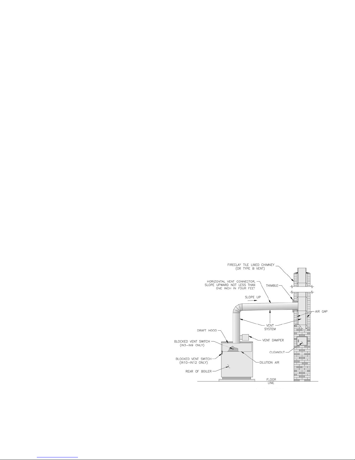
D. Install Vent Connector from draft hood or vent
damper to chimney. See Figure 30.
1. Do not connect into same leg of chimney serving an
open replace.
2. Vent pipe to chimney must not be smaller than outlet
on draft hood or vent damper. Type B is
recommended, but single-wall vent pipe may be
used. Arrange venting system so boiler is served by
vent damper device.
3. Where two or more appliances vent into a common
vent, the area of the common vent should be at least
equal to the area of the largest vent plus 50% of the
area in the additional vent(s). Do not connect the
vent of this appliance into any portion of mechanical
draft systems operating under positive pressure.
4. Horizontal run should be as short as possible. The
maximum length of an uninsulated horizontal run
must not exceed 75% of the height of the chimney.
5. Vent pipe should have the greatest possible initial
rise above draft hood consistent with headroom
available and required clearance from adjacent
combustible building structure. Vent pipe should be
installed above bottom of chimney to prevent
blockage.
6. Vent pipe should slope upward from draft hood to
chimney not less than one inch in four feet. No
portion of vent pipe should run downward or have
dips or sags. Vent pipe must be securely supported.
7. Vent pipe must be inserted into but not beyond
inside wall of chimney liner. Seal tight between vent
pipe and chimney.
E. If an Existing Boiler is Removed:
When an existing boiler is removed from a common
venting system, the common venting system is likely to
be too large for proper venting of the appliances
remaining connected to it.
At the time of removal of an existing boiler, the
following steps shall be followed with each appliance
remaining connected to the common venting system
placed in operation, while the other appliances
remaining connected to the common venting system are
not in operation:
1. Seal any unused openings in the common venting
system.
2. Visually inspect the venting system for proper size
and horizontal pitch and determine there is no
blockage or restriction, leakage, corrosion, and other
deciencies which could cause an unsafe condition.
3. Insofar as is practical, close all building doors and
windows and all doors between the space in which
the appliances remaining connected to the common
venting system are located and other spaces of the
building. Turn on clothes dryers and any appliance
not connected to the common venting system. Turn
on any exhaust fans, such as range-hoods and
bathroom exhausts, so they will operate at maximum
speed. Do not operate a summer exhaust fan. Close
replace dampers.
4. Place in operation the appliance being inspected.
Follow the Lighting (or Operating) Instructions.
Adjust thermostat so appliance will operate
continuously.
5. Test for spillage at the draft hood relief opening
after 5 minutes of main burner operation. Use the
ame of a match or candle, or smoke from a
cigarette, cigar or pipe.
6. After it has been determined that each appliance
remaining connected to the common venting system
properly vents when tested as outlined above, return
doors, windows, exhaust fans, replace dampers and
any other gas-burning appliance to their previous
condition of use.
7. Any improper operation of the common venting
system should be corrected so the installation
conforms with the National Fuel Gas Code, NFPA
54/ANSI Z223.1. When resizing any portion of the
common venting system, the common venting
system should be resized to approach the minimum
size as determined using the appropriate tables in
Part 11 in the National Fuel Gas Code, NFPA 54/
ANSI Z223.1.
26
Figure 30: Typical Vent Installation
Page 27
VIII. Electrical
REGNAD
ronoitallatsnignitpmettaerofebderewopnuerasnoitcennoclacirtcelellaerussaylevitisoP
lacirtcelellatuokcoL.gnidliubroreliobehtfosnoitcennocrostnenopmoclacirtcelefoecivres
.ffodenrutsirewopecnokcoldaphtiwsexob
GNINRAW
lacisyhpsuoiresnitluseryamreliobehtotsnoitcennoclacirtceleeriwylreporpoteruliaF
.mrah
erofebffosirewopllaerusekaM.ecruosenonahterommorfebyamrewoplacirtcelE
.krowlacirtceleynagnitpmetta
.tcennocsiddesufdezisylreporpahtiwdetcetorpebtsumreliobhcaE
.slortnocgnitareporoytefasynaevitareponiekamrotuopmujreveN
A. General. Install wiring and ground boiler in accordance
with requirements of authority having jurisdiction, or in
absence of such requirements the National Electrical
Code, ANSI/NFPA 70 and/or CSA C22.1 Electrical
Code.
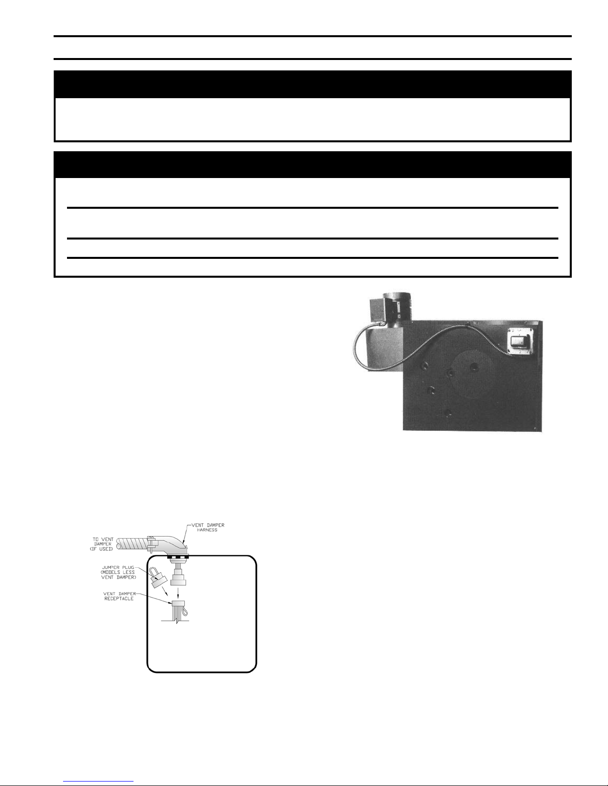
B. Wire Vent Damper (if used).
1. Steam or Water with gravity circulation or tankless
heater.
a. Remove one (1) 7/8" knockout from junction
box. Carefully remove transformer - avoid undue
strain on wires.
b. Install Vent Damper Harness into top of junction
box.
c. Remove factory installed jumper plug (if so
equipped) from Vent Damper Receptacle. Plug
Vent Damper Harness into Vent Damper
Receptacle. See Figure 31.
Figure 32: Vent Damper Harness to Junction Box
2. Water with intermittent circulation and without
tankless heater.
a. Remove 7/8" knockout and cover from limit
control.
b. Install Vent Damper Harness into top of limit.
c. Remove factory installed jumper plug from Vent
Damper Receptacle. Plug Vent Damper Harness
into Vent Damper Receptacle. See Figure 31.
d. Install cable clamp around exible Vent Damper
Harness. Attach to jacket top panel. See Figure
33.
3. Note: After vent damper is installed and operated
through one (1) cycle, the control circuit will
operate only when vent damper is in control circuit.
Figure 31: Vent Damper Connection Detail
d. Install cable clamp around exible Vent Damper
Harness. Attach to jacket top panel. See Figure
32.
C. Install thermostat. Locate on inside wall
approximately 4 feet above oor. Do not install on
outside wall, near replace, or where inuenced by
drafts or restricted air ow, hot or cold pipes, lighting
xtures, television, or sunlight. Allow free air
movement by avoiding placement of furniture near
thermostat.
27
Page 28

Set heat anticipator to match system requirements. See
epyTmetsyS
metsySnoitingI
taeH
rotapicitnA
)1(gnitteS
suounitnoC
)toliPgnidnatS(
)IE(tnettimretnI )PSH(tnettimretnI
eborPhtiwmaetS
ro208-SPrelliM&llennoDcM(
)004-BGClevelordyH
ffotuCretaWwoL
egaP,53erugiF
03
3egaP,63erugiF
2
3egaP,73erugiF
4
8.0
taolFhtiwmaetS
)76relliM&llennoDcM(
ffotuCretaWwoL
3egaP,83erugiF
6
3egaP,93erugiF
8
egaP,04erugiF
04
8.0
)noitalucriCtnettimretnI(retaW
4egaP,14erugiF
2
4egaP,24erugiF
4
4egaP,34erugiF
6
3.0
)noitalucriCytivarG(retaW
4egaP,44erugiF
8
egaP,54erugiF
05
5egaP,64erugiF
2
3.0
retaeHsselknaThtiwretaW
5egaP,74erugiF
4
5egaP,84erugiF
6
5egap,94erugiF
8
6.0
1.0ybgnittesrotapicitnataehecuder,gnitteserutarepmets'tatsomrehtevobataehrevootsdnetmetsysfI)1(
taehesaercni,erutarepmetmoorderisedgnihcaertuohtiwelcyctrohsotsdnetmetsysfI.spma2.0ro
.spma2.0ro1.0ybgnittesrotapicitna
Table 6. In general, setting heat anticipator too low will
cause boiler to short cycle without bringing heated
space up to temperature. Setting heat anticipator too
high will allow boiler to operate longer than necessary
and overheat space.
D. Wire thermostat. Provide Class II circuit between
thermostat and boiler.
1. Steam or Water with gravity circulation or tankless
heater. Remove transformer from junction box.
Connect one wire from thermostat to blue wire(s).
Connect additional wire from thermostat to brown
wire or red wire for water with tankless heater.
2. Water with intermittent circulation and without
tankless heater. Connect one wire from thermostat
to Terminal "T" and additional wire to terminal
"TV".
E. Alliance Indirect Water Heater (if used).
1. For wiring refer to wiring diagrams located in this
section and Alliance Installation Operating and
Service Instructions.
2. Attach junction box extension (4 - 11/16 square) to
junction box on boiler.
3. Steam Boilers only. Verify temperature limit
(Honeywell L4006 or equal, which is installer
supplied) is installed in Tapping "P", refer to
Section V: Piping and Trim.
F. Wire control circuit as shown in the appropriate
wiring diagram. See Table 6.
1. A separate electrical circuit must be run from the
main electrical service with an over-current device/
disconnect in the circuit. A service switch is
recommended and may be required by some local
jurisdictions. Boiler is rated for 120 VAC, 60 hertz,
less than 12 amperes.
2. For zone valve wiring, provide separate 24V
transformer rather than attempting to use boiler
mounted control. Consult zone valve manufacturer
for assistance.
G. Wiring diagram and sequence of operation. Locate
the system type you are interested in from Table 6, then
refer to the page indicated.
Vent Damper Sequence of Operation. See Figure
1.
34.
a. Vent Damper is continuously powered at
Terminal 1.
b. When there is a call for heat, the damper relay
coil is energized through Terminal 5 if all limits
ahead of the damper are satised.
c. Relay coil closes contacts, energizing damper
motor, causing damper to open.
d. When the damper blade reaches the fully open
position, power is sent back to the boiler limit/
ignition circuit through Terminal 2 and the
damper motor is de-energized.
e. When the call for heat is satised, the damper
relay coil is de-energized—closing contacts
which energize the damper motor. This causes
the damper to close. When the damper blade
reaches the fully closed position, the damper
motor is de-energized.
Table 6: Thermostat Heat Anticipator Settings
28
Page 29
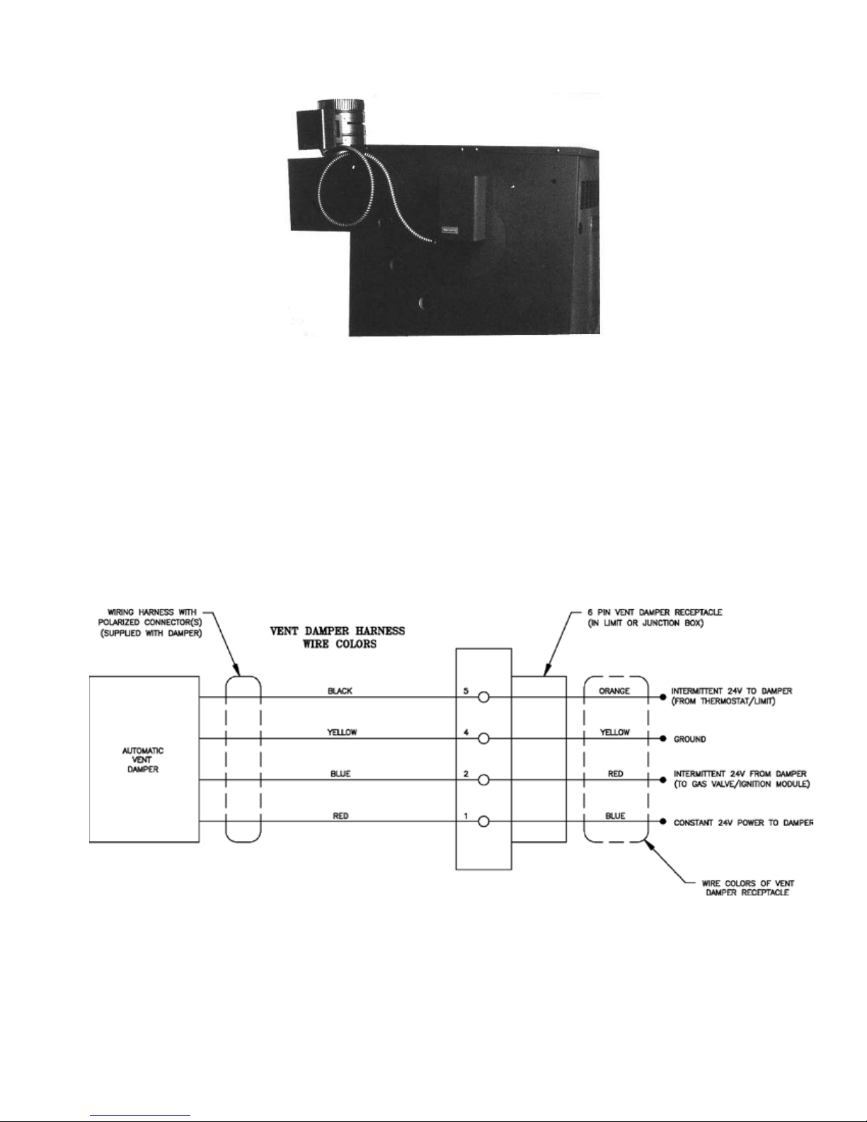
Figure 33: Vent Damper Harness to Limit
Figure 34: Vent Damper Schematic Wiring Diagram
29
Page 30
30
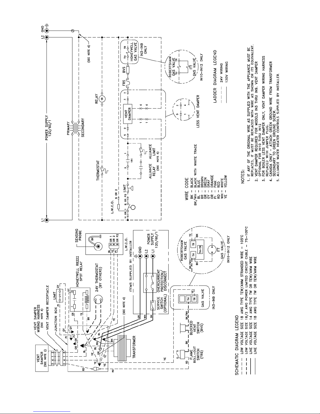
Figure 35: Wiring Diagrams, Steam, Continuous Ignition (Standing Pilot), Probe Low Water Cutoff
Page 31

H. Steam Boiler with Continuous Ignition (Standing Pilot)
and Probe Low Water Cutoff. See Figure 35.
1. Normal Operation
a. Thermostat calls for heat. Thermostat Isolation
Relay is energized, closing contacts.
b. Vent Damper (if used) opens as stated in Vent
Damper Sequence of Operation.
c. Gas Valve(s) is energized allowing main gas ow
and ignition of Main Burners.
d. After Thermostat is satised Gas Valve(s) is de-
energized, extinguishing main ame. Vent
Damper (if used) closes.
Safety Shutdown
2.
a. Limit: Automatically interrupts main burner
operation when steam pressure exceeds set point.
Maximum allowable pressure is 15 psi. Normal
operation resumes when system pressure falls
below set point.
b. Low Water Cutoff (LWCO): Automatically
interrupts main burner operation when surface of
boiler water falls to lowest permissible operating
level. Normal operation resumes when water
returns to normal level.
c. Blocked Vent Switch. Automatically interrupts
main burner operation when excessive vent
system blockage occurs. Control is a multiple
use device. If blocked vent switch is activated do
not attempt to place boiler in operation. Correct
source of blockage and reset blocked vent
switch.
d. Flame Roll-out Switch. Automatically interrupts
boiler operation when ames or excessive heat
are present in vestibule. Control is single use
device. If ame roll-out switch is activated do
not attempt to place boiler in operation. Correct
source of blockage and replace ame roll-out
switch.
e. Thermocouple: senses pilot ame and causes gas
valve to turn off main burner and pilot burner gas
ow should pilot burner ame extinguish.
31
Page 32

32
Figure 36: Wiring Diagrams, Steam, Intermittent Ignition (EI), Probe Low Water Cutoff
Page 33

I. Steam Boiler with Intermittent Ignition (EI) and Probe
Low Water Cutoff. See Figure 36.
1. Normal Operation
a. Thermostat calls for heat. Thermostat Isolation
Relay is energized, closing contacts.
b. Vent Damper (if used) opens as stated in Vent
Damper Sequence of Operation.
c. Ignition Module is energized. Pilot Valve opens
and Igniter is energized to ignite Pilot Burner.
d. Sensor proves presence of pilot ame. Main
Valve(s) opens and ignites Main Burners.
e. After Thermostat is satised Ignition Module is
de-energized, extinguishing pilot and main
ame. Vent Damper (if used) closes.
2. Safety Shutdown
a. Limit: Automatically interrupts main burner
operation when steam pressure exceeds set point.
Maximum allowable pressure is 15 psi. Normal
operation resumes when system pressure falls
below set point.
b. Low Water Cutoff (LWCO): Automatically
interrupts main burner operation when surface of
boiler water falls to lowest permissible operating
level. Normal operation resumes when water
returns to normal level.
c. Blocked Vent Switch. Automatically interrupts
main burner operation when excessive vent
system blockage occurs. Control is a multiple
use device. If blocked vent switch is activated do
not attempt to place boiler in operation. Correct
source of blockage and reset blocked vent
switch.
d. Flame Roll-out Switch. Automatically interrupts
boiler operation when ames or excessive heat
are present in vestibule. Control is single use
device. If ame roll-out switch is activated do
not attempt to place boiler in operation. Correct
source of blockage and replace ame roll-out
switch.
e. Igniter/Sensor: senses pilot ame and causes
ignition module to turn off main burner and pilot
burner gas ow should pilot burner ame
extinguish. Five to six minutes after shutdown,
Ignition Module restarts ignition sequence.
For Electronic Ignition Trouble Shooting Guide, see
Page 74.
33
Page 34

34
Figure 37: Wiring Diagrams, Steam, Intermittent Ignition (HSP), Probe Low Water Cutoff
Page 35

J. Steam Boiler with Intermittent Ignition (HSP) and
Probe Low Water Cutoff. See Figure 37.
1. Normal Operation
a. Thermostat calls for heat. Thermostat Isolation
Relay is energized, closing contacts.
b. Vent Damper (if used) opens as stated in Vent
Damper Sequence of Operation.
c. Gas Valve is energized. Igniter is energized and
Pilot Valve opens to ignite Pilot Burner.
d. Sensor proves presence of pilot ame and Gas
Valve de-energizes igniter. Main Valve opens
and ignites Main Burners.*
e. After Thermostat is satised Gas Valve is de-
energized, extinguishing pilot and main ame.
Vent Damper (if used) closes.
2. Safety Shutdown
a. Limit: Automatically interrupts main burner
operation when steam pressure exceeds set point.
Maximum allowable pressure is 15 psi. Normal
operation resumes when system pressure falls
below set point.
b. Low Water Cutoff (LWCO): Automatically
interrupts main burner operation when surface of
boiler water falls to lowest permissible operating
level. Normal operation resumes when water
returns to normal level.
c. Blocked Vent Switch. Automatically interrupts
main burner operation when excessive vent
system blockage occurs. Control is a multiple
use device. If blocked vent switch is activated do
not attempt to place boiler in operation. Correct
source of blockage and reset blocked vent
switch.
d. Flame Roll-out Switch. Automatically interrupts
boiler operation when ames or excessive heat
are present in vestibule. Control is single use
device. If ame roll-out switch is activated do
not attempt to place boiler in operation. Correct
source of blockage and replace ame roll-out
switch.
e. Sensor: senses pilot ame and causes Gas Valve
to interrupt main burner and pilot burner gas
ow should pilot burner ame extinguish.
For Hot Surface to Pilot Trouble Shooting Guide, see
Page 75.
* • SV9500 and SV9600 Gas Valves:
The igniter and pilot gas valve will stay
energized until either the pilot lights or the call
for heat ends.
• SV9501 and SV9601 Gas Valves:
If the pilot fails to light after a 90 second trial for
ignition, the igniter will be de-energized and the
pilot gas valve will close. After a 5 minute delay,
the igniter will be re-energized and the pilot gas
valve will re-open. This continuous retry cycle
will end either when the pilot lights or the call
for heat ends.
35
Page 36

36
Figure 38: Wiring Diagrams, Steam, Continuous Ignition (Standing Pilot), Float Low Water Cutoff
Page 37

K. Steam Boiler with Continuous Ignition (Standing Pilot)
and Float Low Water Cutoff. See Figure 38.
1. Normal Operation
a. Thermostat calls for heat. Thermostat Isolation
Relay is energized, closing contacts.
b. Vent Damper (if used) opens as stated in Vent
Damper Sequence of Operation.
c. Gas Valve(s) is energized allowing main gas ow
and ignition of Main Burners.
d. After Thermostat is satised Gas Valve(s) is de-
energized, extinguishing main ame. Vent
Damper (if used) closes.
Safety Shutdown
2.
a. Limit: Automatically interrupts main burner
operation when steam pressure exceeds set point.
Maximum allowable pressure is 15 psi. Normal
operation resumes when system pressure falls
below set point.
b. Low Water Cutoff (LWCO): Automatically
interrupts main burner operation when surface of
boiler water falls to lowest permissible operating
level. Normal operation resumes when water
returns to normal level.
c. Blocked Vent Switch. Automatically interrupts
main burner operation when excessive vent
system blockage occurs. Control is a multiple
use device. If blocked vent switch is activated do
not attempt to place boiler in operation. Correct
source of blockage and reset blocked vent
switch.
d. Flame Roll-out Switch. Automatically interrupts
boiler operation when ames or excessive heat
are present in vestibule. Control is single use
device. If ame roll-out switch is activated do
not attempt to place boiler in operation. Correct
source of blockage and replace ame roll-out
switch.
e. Thermocouple: senses pilot ame and causes gas
valve to turn off main burner and pilot burner gas
ow should pilot burner ame extinguish.
37
Page 38

38
Figure 39: Wiring Diagrams, Steam, Intermittent Ignition (EI), Float Low Water Cutoff
Page 39

L. Steam Boiler with Intermittent Ignition (EI) and Float
Low Water Cutoff. See Figure 39.
1. Normal Operation
a. Thermostat calls for heat. Thermostat Isolation
Relay is energized, closing contacts.
b. Vent Damper (if used) opens as stated in Vent
Damper Sequence of Operation.
c. Ignition Module is energized. Pilot Valve opens
and Igniter is energized to ignite Pilot Burner.
d. Sensor proves presence of pilot ame. Main
Valve(s) opens and ignites Main Burners.
e. After Thermostat is satised Ignition Module is
de-energized, extinguishing pilot and main
ame. Vent Damper (if used) closes.
2. Safety Shutdown
a. Limit: Automatically interrupts main burner
operation when steam pressure exceeds set point.
Maximum allowable pressure is 15 psi. Normal
operation resumes when system pressure falls
below set point.
b. Low Water Cutoff (LWCO): Automatically
interrupts main burner operation when surface of
boiler water falls to lowest permissible operating
level. Normal operation resumes when water
returns to normal level.
c. Blocked Vent Switch. Automatically interrupts
main burner operation when excessive vent
system blockage occurs. Control is a multiple
use device. If blocked vent switch is activated do
not attempt to place boiler in operation. Correct
source of blockage and reset blocked vent
switch.
d. Flame Roll-out Switch. Automatically interrupts
boiler operation when ames or excessive heat
are present in vestibule. Control is single use
device. If ame roll-out switch is activated do
not attempt to place boiler in operation. Correct
source of blockage and replace ame roll-out
switch.
e. Igniter/Sensor: senses pilot ame and causes
ignition module to turn off main burner and pilot
burner gas ow should pilot burner ame
extinguish. Five to six minutes after shutdown,
Ignition Module restarts ignition sequence.
For Electronic Ignition Trouble Shooting Guide, see
Page 74.
39
Page 40

40
Figure 40: Wiring Diagrams, Steam, Intermittent Ignition (HSP), Float Low Water Cutoff
Page 41

M. Steam Boiler with Intermittent Ignition (HSP) and Float
Low Water Cutoff. See Figure 40.
1. Normal Operation
a. Thermostat calls for heat. Thermostat Isolation
Relay is energized, closing contacts.
b. Vent Damper (if used) opens as stated in Vent
Damper Sequence of Operation.
c. Gas Valve is energized. Igniter is energized and
Pilot Valve opens to ignite Pilot Burner.
d. Sensor proves presence of pilot ame and Gas
Valve de-energizes igniter. Main Valve opens
and ignites Main Burners.*
e. After Thermostat is satised Gas Valve is de-
energized, extinguishing pilot and main ame.
Vent Damper (if used) closes.
2. Safety Shutdown
a. Limit: Automatically interrupts main burner
operation when steam pressure exceeds set point.
Maximum allowable pressure is 15 psi. Normal
operation resumes when system pressure falls
below set point.
b. Low Water Cutoff (LWCO): Automatically
interrupts main burner operation when surface of
boiler water falls to lowest permissible operating
level. Normal operation resumes when water
returns to normal level.
c. Blocked Vent Switch. Automatically interrupts
main burner operation when excessive vent
system blockage occurs. Control is a multiple
use device. If blocked vent switch is activated do
not attempt to place boiler in operation. Correct
source of blockage and reset blocked vent
switch.
d. Flame Roll-out Switch. Automatically interrupts
boiler operation when ames or excessive heat
are present in vestibule. Control is single use
device. If ame roll-out switch is activated do
not attempt to place boiler in operation. Correct
source of blockage and replace ame roll-out
switch.
e. Sensor: senses pilot ame and causes Gas Valve
to interrupt main burner and pilot burner gas
ow should pilot burner ame extinguish.
For Hot Surface to Pilot Trouble Shooting Guide, see
Page 75.
* • SV9500 and SV9600 Gas Valves:
The igniter and pilot gas valve will stay
energized until either the pilot lights or the call
for heat ends.
• SV9501 and SV9601 Gas Valves:
If the pilot fails to light after a 90 second trial for
ignition, the igniter will be de-energized and the
pilot gas valve will close. After a 5 minute delay,
the igniter will be re-energized and the pilot gas
valve will re-open. This continuous retry cycle
will end either when the pilot lights or the call
for heat ends.
41
Page 42

42
Figure 41: Wiring Diagrams, Water, Continuous Ignition (Standing Pilot), Intermittent Circulation
Page 43

N. Water Boiler with Continuous Ignition (Standing Pilot)
and Intermittent Circulation. See Figure 41.
1. Normal Operation
a. Thermostat calls for heat.
b. Vent Damper (if used) opens as stated in Vent
Damper Sequence of Operation.
c. Gas Valve(s) is energized allowing main gas ow
and ignition of Main Burners.
d. After Thermostat is satised Gas Valve(s) is de-
energized, extinguishing main ame. Vent
Damper (if used) closes.
Safety Shutdown
2.
a. Limit: Automatically interrupts main burner
operation when water temperature exceeds set
point. Maximum allowable temperature is 250°F.
Normal operation resumes when water
temperature falls below set point.
b. Blocked Vent Switch. Automatically interrupts
main burner operation when excessive vent
system blockage occurs. Control is a multiple
use device. If blocked vent switch is activated do
not attempt to place boiler in operation. Correct
source of blockage and reset blocked vent
switch.
c. Flame Roll-out Switch. Automatically interrupts
boiler operation when ames or excessive heat
are present in vestibule. Control is single use
device. If ame roll-out switch is activated do
not attempt to place boiler in operation. Correct
source of blockage and replace ame roll-out
switch.
d. Thermocouple: senses pilot ame and causes gas
valve to turn off main burner and pilot burner gas
ow should pilot burner ame extinguish.
43
Page 44

44
Figure 42: Wiring Diagrams, Water, Intermittent Ignition (EI), Intermittent Circulation
Page 45

O. Water Boiler with Intermittent Ignition (EI) and
Intermittent Circulation. See Figure 42.
1. Normal Operation
a. Thermostat calls for heat.
b. Vent Damper (if used) opens as stated in Vent
Damper Sequence of Operation.
c. Ignition Module is energized. Pilot Valve opens
and Igniter is energized to ignite Pilot Burner.
d. Sensor proves presence of pilot ame. Main
Valve(s) opens and ignites Main Burners.
e. After Thermostat is satised Ignition Module is
de-energized, extinguishing pilot and main
ame. Vent Damper (if used) closes.
2. Safety Shutdown
a. Limit: Automatically interrupts main burner
operation when water temperature exceeds set
point. Maximum allowable temperature is 250°F.
Normal operation resumes when water
temperature falls below set point.
b. Blocked Vent Switch. Automatically interrupts
main burner operation when excessive vent
system blockage occurs. Control is a multiple
use device. If blocked vent switch is activated do
not attempt to place boiler in operation. Correct
source of blockage and reset blocked vent
switch.
c. Flame Roll-out Switch. Automatically interrupts
boiler operation when ames or excessive heat
are present in vestibule. Control is single use
device. If ame roll-out switch is activated do
not attempt to place boiler in operation. Correct
source of blockage and replace ame roll-out
switch.
d. Igniter/Sensor: senses pilot ame and causes
ignition module to turn off main burner and pilot
burner gas ow should pilot burner ame
extinguish. Five to six minutes after shutdown,
Ignition Module restarts ignition sequence.
For Electronic Ignition Trouble Shooting Guide, see
Page 74.
45
Page 46

46
Figure 43: Wiring Diagrams, Water, Intermittent Ignition (HSP), Intermittent Circulation
Page 47

P. Water Boiler with Intermittent Ignition (HSP) and
Intermittent Circulation. See Figure 43.
1. Normal Operation
a. Thermostat calls for heat.
b. Vent Damper (if used) opens as stated in Vent
Damper Sequence of Operation.
c. Gas Valve is energized. Igniter is energized and
Pilot Valve opens to ignite Pilot Burner.
d. Sensor proves presence of pilot ame and Gas
Valve de-energizes igniter. Main Valve opens
and ignites Main Burners.*
e. After Thermostat is satised Gas Valve is de-
energized, extinguishing pilot and main ame.
Vent Damper (if used) closes.
2. Safety Shutdown
a. Limit: Automatically interrupts main burner
operation when water temperature exceeds set
point. Maximum allowable temperature is 250°F.
Normal operation resumes when water
temperature falls below set point.
b. Blocked Vent Switch. Automatically interrupts
main burner operation when excessive vent
system blockage occurs. Control is a multiple
use device. If blocked vent switch is activated do
not attempt to place boiler in operation. Correct
source of blockage and reset blocked vent
switch.
c. Flame Roll-out Switch. Automatically interrupts
boiler operation when ames or excessive heat
are present in vestibule. Control is single use
device. If ame roll-out switch is activated do
not attempt to place boiler in operation. Correct
source of blockage and replace ame roll-out
switch.
d. Sensor: senses pilot ame and causes Gas Valve
to interrupt main burner and pilot burner gas
ow should pilot burner ame extinguish.
For Hot Surface to Pilot Trouble Shooting Guide, see
Page 75.
* • SV9500 and SV9600 Gas Valves:
The igniter and pilot gas valve will stay
energized until either the pilot lights or the call
for heat ends.
• SV9501 and SV9601 Gas Valves:
If the pilot fails to light after a 90 second trial for
ignition, the igniter will be de-energized and the
pilot gas valve will close. After a 5 minute delay,
the igniter will be re-energized and the pilot gas
valve will re-open. This continuous retry cycle
will end either when the pilot lights or the call
for heat ends.
47
Page 48

48
Figure 44: Wiring Diagrams, Water, Continuous Ignition (Standing Pilot), Gravity Circulation
Page 49

Q. Water Boiler with Continuous Ignition (Standing Pilot)
and Gravity Circulation. See Figure 44.
1. Normal Operation
a. Thermostat calls for heat. Thermostat Isolation
Relay is energized, closing contacts.
b. Vent Damper (if used) opens as stated in Vent
Damper Sequence of Operation.
c. Gas Valve(s) is energized allowing main gas ow
and ignition of Main Burners.
d. After Thermostat is satised Gas Valve(s) is de-
energized, extinguishing main ame. Vent
Damper (if used) closes.
Safety Shutdown
2.
a. Limit: Automatically interrupts main burner
operation when water temperature exceeds set
point. Maximum allowable temperature is 250°F.
Normal operation resumes when water
temperature falls below set point.
b. Blocked Vent Switch. Automatically interrupts
main burner operation when excessive vent
system blockage occurs. Control is a multiple
use device. If blocked vent switch is activated do
not attempt to place boiler in operation. Correct
source of blockage and reset blocked vent
switch.
c. Flame Roll-out Switch. Automatically interrupts
boiler operation when ames or excessive heat
are present in vestibule. Control is single use
device. If ame roll-out switch is activated do
not attempt to place boiler in operation. Correct
source of blockage and replace ame roll-out
switch.
d. Thermocouple: senses pilot ame and causes gas
valve to turn off main burner and pilot burner gas
ow should pilot burner ame extinguish.
49
Page 50

50
Figure 45: Wiring Diagrams, Water, Intermittent Ignition (EI), Gravity Circulation
Page 51

R. Water Boiler with Intermittent Ignition (EI) and Gravity
Circulation. See Figure 45.
1. Normal Operation
a. Thermostat calls for heat. Thermostat Isolation
Relay is energized, closing contacts.
b. Vent Damper (if used) opens as stated in Vent
Damper Sequence of Operation.
c. Ignition Module is energized. Pilot Valve opens
and Igniter is energized to ignite Pilot Burner.
d. Sensor proves presence of pilot ame. Main
Valve(s) opens and ignites Main Burners.
e. After Thermostat is satised Ignition Module is
de-energized, extinguishing pilot and main
ame. Vent Damper (if used) closes.
2. Safety Shutdown
a. Limit: Automatically interrupts main burner
operation when water temperature exceeds set
point. Maximum allowable temperature is 250°F.
Normal operation resumes when water
temperature falls below set point.
b. Blocked Vent Switch. Automatically interrupts
main burner operation when excessive vent
system blockage occurs. Control is a multiple
use device. If blocked vent switch is activated do
not attempt to place boiler in operation. Correct
source of blockage and reset blocked vent
switch.
c. Flame Roll-out Switch. Automatically interrupts
boiler operation when ames or excessive heat
are present in vestibule. Control is single use
device. If ame roll-out switch is activated do
not attempt to place boiler in operation. Correct
source of blockage and replace ame roll-out
switch.
d. Igniter/Sensor: senses pilot ame and causes
ignition module to turn off main burner and pilot
burner gas ow should pilot burner ame
extinguish. Five to six minutes after shutdown,
Ignition Module restarts ignition sequence.
For Electronic Ignition Trouble Shooting Guide, see
Page 74.
51
Page 52

52
Figure 46: Wiring Diagrams, Water, Intermittent Ignition (HSP), Gravity Circulation
Page 53

S. Water Boiler with Intermittent Ignition (HSP) and
Gravity Circulation. See Figure 46.
1. Normal Operation
a. Thermostat calls for heat. Thermostat Isolation
Relay is energized, closing contacts.
b. Vent Damper (if used) opens as stated in Vent
Damper Sequence of Operation.
c. Gas Valve is energized. Igniter is energized and
Pilot Valve opens to ignite Pilot Burner.
d. Sensor proves presence of pilot ame and Gas
Valve de-energizes igniter. Main Valve opens
and ignites Main Burners.*
e. After Thermostat is satised Gas Valve is de-
energized, extinguishing pilot and main ame.
Vent Damper (if used) closes.
2. Safety Shutdown
a. Limit: Automatically interrupts main burner
operation when water temperature exceeds set
point. Maximum allowable temperature is 250°F.
Normal operation resumes when water
temperature falls below set point.
b. Blocked Vent Switch. Automatically interrupts
main burner operation when excessive vent
system blockage occurs. Control is a multiple
use device. If blocked vent switch is activated do
not attempt to place boiler in operation. Correct
source of blockage and reset blocked vent
switch.
c. Flame Roll-out Switch. Automatically interrupts
boiler operation when ames or excessive heat
are present in vestibule. Control is single use
device. If ame roll-out switch is activated do
not attempt to place boiler in operation. Correct
source of blockage and replace ame roll-out
switch.
d. Sensor: senses pilot ame and causes Gas Valve
to interrupt main burner and pilot burner gas
ow should pilot burner ame extinguish.
For Hot Surface to Pilot Trouble Shooting Guide, see
Page 75.
* • SV9500 and SV9600 Gas Valves:
The igniter and pilot gas valve will stay
energized until either the pilot lights or the call
for heat ends.
• SV9501 and SV9601 Gas Valves:
If the pilot fails to light after a 90 second trial for
ignition, the igniter will be de-energized and the
pilot gas valve will close. After a 5 minute delay,
the igniter will be re-energized and the pilot gas
valve will re-open. This continuous retry cycle
will end either when the pilot lights or the call
for heat ends.
53
Page 54

54
Figure 47: Wiring Diagrams, Water, Continuous Ignition (Standing Pilot), Tankless Heater
Page 55

T. Water Boiler with Continuous Ignition (Standing Pilot)
and Tankless Heater. See Figure 47.
1. Normal Operation
a. Thermostat calls for heat or low limit senses
water temperature below set point.
b. Vent Damper (if used) opens as stated in Vent
Damper Sequence of Operation.
c. Gas Valve(s) is energized allowing main gas ow
and ignition of Main Burners.
d. After Thermostat or low limit is satised Gas
Valve(s) is de-energized, extinguishing main
ame. Vent Damper (if used) closes.
Safety Shutdown
2.
a. Limit: Automatically interrupts main burner
operation when water temperature exceeds set
point. Maximum allowable temperature is 250°F.
Normal operation resumes when water
temperature falls below set point.
b. Blocked Vent Switch. Automatically interrupts
main burner operation when excessive vent
system blockage occurs. Control is a multiple
use device. If blocked vent switch is activated do
not attempt to place boiler in operation. Correct
source of blockage and reset blocked vent
switch.
c. Flame Roll-out Switch. Automatically interrupts
boiler operation when ames or excessive heat
are present in vestibule. Control is single use
device. If ame roll-out switch is activated do
not attempt to place boiler in operation. Correct
source of blockage and replace ame roll-out
switch.
d. Thermocouple: senses pilot ame and causes gas
valve to turn off main burner and pilot burner gas
ow should pilot burner ame extinguish.
55
Page 56

56
Figure 48: Wiring Diagrams, Water, Intermittent Ignition (EI), Tankless Heater
Page 57

U. Water Boiler with Intermittent Ignition (EI) and
Tankless Heater. See Figure 48.
1. Normal Operation
a. Thermostat calls for heat or low limit senses
water temperature below set point.
b. Vent Damper (if used) opens as stated in Vent
Damper Sequence of Operation.
c. Ignition Module is energized. Pilot Valve opens
and Igniter is energized to ignite Pilot Burner.
d. Sensor proves presence of pilot ame. Main
Valve(s) opens and ignites Main Burners.
e. After Thermostat or low limit is satised Ignition
Module is de-energized, extinguishing pilot and
main ame. Vent Damper (if used) closes.
2. Safety Shutdown
a. Limit: Automatically interrupts main burner
operation when water temperature exceeds set
point. Maximum allowable temperature is 250°F.
Normal operation resumes when water
temperature falls below set point.
b. Blocked Vent Switch. Automatically interrupts
main burner operation when excessive vent
system blockage occurs. Control is a multiple
use device. If blocked vent switch is activated do
not attempt to place boiler in operation. Correct
source of blockage and reset blocked vent
switch.
c. Flame Roll-out Switch. Automatically interrupts
boiler operation when ames or excessive heat
are present in vestibule. Control is single use
device. If ame roll-out switch is activated do
not attempt to place boiler in operation. Correct
source of blockage and replace ame roll-out
switch.
d. Igniter/Sensor: senses pilot ame and causes
ignition module to turn off main burner and pilot
burner gas ow should pilot burner ame
extinguish. Five to six minutes after shutdown,
Ignition Module restarts ignition sequence.
For Electronic Ignition Trouble Shooting Guide, see
Page 74.
57
Page 58

58
Figure 49: Wiring Diagrams, Water, Intermittent Ignition (HSP), Tankless Heater
Page 59

V. Water Boiler with Intermittent Ignition (HSP) and
Tankless Heater. See Figure 49.
Normal Operation
1.
a. Thermostat calls for heat or low limit senses
water temperature below set point.
b. Vent Damper (if used) opens as stated in Vent
Damper Sequence of Operation.
c. Gas Valve is energized. Igniter is energized and
Pilot Valve opens to ignite Pilot Burner.
d. Sensor proves presence of pilot ame and Gas
Valve de-energizes igniter. Main Valve opens
and ignites Main Burners.*
e. After Thermostat is satised Gas Valve is de-
energized, extinguishing pilot and main ame.
Vent Damper (if used) closes.
2. Safety Shutdown
a. Limit: Automatically interrupts main burner
operation when water temperature exceeds set
point. Maximum allowable temperature is 250°F.
Normal operation resumes when water
temperature falls below set point.
b. Blocked Vent Switch. Automatically interrupts
main burner operation when excessive vent
system blockage occurs. Control is a multiple
use device. If blocked vent switch is activated do
not attempt to place boiler in operation. Correct
source of blockage and reset blocked vent
switch.
c. Flame Roll-out Switch. Automatically interrupts
boiler operation when ames or excessive heat
are present in vestibule. Control is single use
device. If ame roll-out switch is activated do
not attempt to place boiler in operation. Correct
source of blockage and replace ame roll-out
switch.
d. Sensor: senses pilot ame and causes Gas Valve
to interrupt main burner and pilot burner gas
ow should pilot burner ame extinguish.
For Hot Surface to Pilot Trouble Shooting Guide, see
Page 75.
* • SV9500 and SV9600 Gas Valves:
The igniter and pilot gas valve will stay
energized until either the pilot lights or the call
for heat ends.
• SV9501 and SV9601 Gas Valves:
If the pilot fails to light after a 90 second trial for
ignition, the igniter will be de-energized and the
pilot gas valve will close. After a 5 minute delay,
the igniter will be re-energized and the pilot gas
valve will re-open. This continuous retry cycle
will end either when the pilot lights or the call
for heat ends.
59
Page 60

IX. System Start-up
GNINRAW
llawollofdnadnatsrednu,daeryletelpmoC
erofeblaunamsihtnisnoitcurtsni
.putratsgnitpmetta
A. Safe lighting and other performance criteria were met
with the gas manifold and control assembly provided on
boiler when boiler underwent tests specied in
American National Standard for Gas-Fired LowPressure Steam and Hot Water Boilers, ANSI Z21.13.
B. Check Main Burners. Main burners must be in slots in
rear of burner tray and seated on main burner orices.
C. Fill boiler with water:
1. Steam: ll to normal water line. See Figure 1.
2. Water: ll heating system to approximately 12 PSI.
Vent air from system.
D. Prepare to check operation.
1. Obtain gas heating value (in Btu per cubic foot)
from gas supplier.
2. Adjust limit:
a. Steam: With an L404A1354 - set cut-out
pressure (MAIN scale) on the pressure limit for
(2) PSI and differential pressure (DIFF. scale)
below (2) PSI.
With an L404A1651 or an L404F1367 - set cut-
out pressure (MAIN scale) on the pressure limit
for (1) PSI and differential pressure (DIFF.) for
.5 PSI. These pressures may be varied to suit
individual requirements of the system. See
Figure 18A or 18B.
b. Water without tankless heater: set at 200°F.
c. Water with tankless heater: set limit at 220°F and
operating control to 200°F.
3. Remove front removable panel. See Figure 50.
Figure 51: Gas Valve Pressure Tap,
Honeywell Gas Valves
Figure 52: Gas Valve Pressure Tap,
Robertshaw Gas Valve
4. Connect manometer to gas valve pressure tapping
(for IN12 connect to gas valve with pilot control).
See Figure 51 or 52.
5. For natural gas red boiler, temporarily turn off all
other gas-red appliances.
Figure 50: Front Door Removal
60
E. Follow Lighting or Operating Instructions.
1. To place boiler in operation. See Figure 53, 54, 55,
56 or 57. Sequence of Operation is outlined with
wiring diagrams in Section VIII: Electrical.
2. Electronic Ignition Modules with LED indicators.
Table 7 cross-references the ignition module
terminal designations to the ignition terminal
numbers in the wiring ladder diagrams. The yellow
LED indicates the status of the ame, see Table 8.
The green LED indicates the status of the system,
see Table 9. See Figure 58 for LED locations.
Page 61

Figure 53: Lighting Instructions, Continuous Ignition System, VR8200 and VR8300 Gas Valves
61
Page 62

Figure 54: Lighting Instructions, Continuous Ignition System, 7000 ERHC Gas Valve
62
Page 63

Figure 55: Operating Instruction, Intermittent Ignition System, SV9500, SV9600, VR8204 and VR8304
(except IN12) Gas Valves
63
Page 64

Figure 56: Operating Instructions, Intermittent Ignition System (EI), VR8304 (IN12 only) Gas Valves
64
Page 65

Figure 57: Operating Instructions, Intermittent Ignition System (HSP), SV9501 and SV9601
65
Page 66

Table 7: Ignition Module Terminal Cross-Reference
Ignition Module
Terminal Designation
MV 1
MV/PV 2
PV 3
GND 4
24V (GND) 5
24V 6
SPARK 9
TABLE 8: Yellow LED Flame Codes
Yellow LED
Flash Code
Heartbeat Normal Flame Signal N/A
2
1
OFF
a
Flash Code Descriptions
Wiring Ladder Diagram
Terminal Number
a
Indicates
Weak Flame Signal -
System will operate reliably but ame signal is
less than desired.
Note: This indication may ash temporarily
during or shortly after lightoff on some
applications.
Marginal Flame Signal (less than 1.1 µA) -
System may not operate reliably over time.
Service call recommended.
Note: This indication may ash temporarily
during or shortly after lightoff on some
applications.
No Flame or Flame Signal -
below minimum threshold for system operation.
Figure 58: LED Locations
Recommended
Service Action
Perform routine
maintenance to
assure optimum
ame signal.
Check gas supply,
pilot burner, ame
sense wiring,
contamination of
ame rod, burner
ground connection.
N/A
- Heartbeat: Constant ½ second bright, ½ second dim cycles.
- The ash code number signies that the LED ashes X times at 2Hz, remains
off for two seconds, and then repeats sequence.
66
Page 67

Table 9: Green LED Status Codes
Green LED
Flash Code
(X + Y)
Flash Fast
Heartbeat Normal operation N/A None
a
Flash Code Descriptions:
a
OFF No “Call for Heat” N/A None
Startup - Flame sense
calibration
5 minute Retry Delay-
2
Pilot ame not detected
during trial for ignition
3
4
7
8
Recycle- Flame failed
during run
Flame sensed out of
sequence
Flame sense leakage to
ground
Low secondary voltage
supply- (below 15.5 Vac)
5 minute Retry Delay-
6 + 2
On every third retry on
same “Call for Heat”
On every 6th ame
6 + 3
failure during run on the
same “Call for Heat”
Flame sensed out of
6 + 4
sequence- longer than
10 seconds
Soft lockout due to error
ON
detected during self
check sequences
- Flash Fast: rapid blinking
- Heartbeat: Constant ½ second bright, ½ second dim cycles.
- A single ash code number signies that the LED ashes X times at 2Hz, remains off for two seconds, and then
repeats the sequence.
- X + Y ash codes signify that the LED ashes X times at 2Hz, remains off for two seconds, ashes Y times at 2
Hz, remains off for three seconds, and then repeats the sequence.
Indicates Next System Action Recommended Service Action
N/A None
If system fails to light on next trial
for ignition check gas supply, pilot
Initiate new trial for ignition after retry
delay completed.
Initiate new trial for ignition. Flash
code will remain through the ignition
trial until ame is proved.
If situation self corrects within 10
seconds, control returns to normal
sequence. If ame out of sequence remains longer than 10 seconds, control
goes to Flash code 6+4 (see below)
Control remains in wait mode. When
the fault corrects, control resumes nor-
mal operation after a one minute delay.
Control remains in wait mode. When
the fault corrects, control resumes nor-
mal operation after one minute delay.
Initiate new trial for ignition after retry
delay completed.
5 minute retry delay, then initiate new
trial for ignition.
Control waits until ame is no longer
sensed and then goes to soft lockout.
Flash code continues. Control auto
resets from soft lockout after one hour.
Control auto resets from soft lockout
after one hour.
burner, spark and ame sense wir-
ing, ame rod contamination or out
of position, burner ground connec-
tion.
If system fails to light on next trial
for ignition check gas supply, pilot
burner, ame sense wiring, ame
rod contamination, burner ground
connection.
Check for pilot ame. Replace gas
valve if pilot ame present. If no
pilot ame, cycle “Call for Heat.” If
error repeats, replace control.
Check ame sense lead wire for
damage or shorting. Check that
ame rod is in proper position.
Check ame rod ceramic for cracks,
damage or tracking.
Check transformer and AC line for
proper input voltage to the control.
Check with full system load on the
transformer.
Check gas supply, pilot burner, spark
and ame sense wiring, ame rod
contamination or out of position,
burner ground connection.
Check gas supply, pilot burner, ame
sense wiring, contamination of ame
rod, burner ground connection.
Check for pilot ame. Replace gas
valve if pilot ame present. If no
pilot ame, cycle “Call for Heat.” If
error repeats, replace control.
Reset by cycling “Call for Heat.” If
error repeats, replace the control
67
Page 68

Figure 59: Pilot Burner Flame, Honeywell Q350
Figure 62: Pilot Burner Flame, Honeywell Q3480
Figure 60: Pilot Burner Flame, Honeywell Q327
Figure 61: Pilot Burner Flame, Honeywell Q348
68
Figure 63: 40mm Main Burner Flame
Figure 64: 1" Main Burner Flame
Page 69

F. Checkpilotburnerameandmainburnerames
NOITUAC
tnemnorivnenanireliobsihtgnitarepodiovA
yrd,srebifnoitalusniesool,tsudwaserehw
sireliobfI.tneserpera.cte,tsudllaw
renrubeht,snoitidnocesehtrednudetarepo
dnadenaelcebtsumstropdnaroiretni
.noitareporeporperusniotyliaddetcepsni
NOITUAC
.ssalgeguagwolebniardtonoD
GNINRAW
lliwetartupnisagtsujdaylreporpoteruliaF
ehtfognirifrednurognirifrevonitluser
reliobefasnudnareporpmI.ecnailppa
.tluseryamnoitarepo
through observation port.
1. Check pilot ame.
a. Continuous Ignition (Standing Pilot), Models
IN3 through IN7. See Figure 59. Pilot burner
produces a single ame. Flame should be steady,
medium hard blue enveloping 3/8 to ½ inch of
thermocouple.
b. Continuous Ignition (Standing Pilot), Models
IN8 through IN12. See Figure 60. Pilot burner
produces three (3) ames. Center ame should
be steady, medium hard blue enveloping 3/8 to ½
inch of thermocouple.
c. Electronic Ignition (EI), Models IN3 through
IN12. See Figure 61. Pilot should be lit only
after completing Step 3. Pilot burner produces
three (3) ames. Center ame should be steady,
medium hard blue enveloping 3/8 to ½ inch of
sensing probe.
2. With boiler operating, open drain and slowly drain
boiler.
3. Main burners will extinguish when water level drops
below low water cutoff. Water should still be visible
in gauge glass. Verify limit, thermostat or other
controls have not shut off boiler.
4. Adjust thermostat to lowest setting. Rell boiler to
normal water line.
J. Check Limit.
1. Adjust thermostat to highest setting.
2. Steam: Observe pressure gauge. When pressure is
indicated, adjust limit to setting below observed
pressure. Main burners should extinguish.
d. Hot Surface to Pilot Ignition (HSP), Models IN3
through IN9. See Figure 62. Pilot should be lit
only after completing Step 3. Pilot burner
produces three (3) ames. Center ame should
be steady, medium hard blue enveloping 3/8 to ½
inch of sensing probe.
2. Adjust thermostat to highest setting.
3. Check main burner ames. See Figure 63 or 64.
Flame should have clearly dened inner cones with
no yellow tipping. Orange-yellow streaks caused by
dust should not be confused with true yellow
tipping.
4. Adjust thermostat to normal setting.
G. Check thermostat operation. Raise and lower
temperature setting to start and stop boiler operation.
H. Check ignition system shutoff. Gas valve should close
and pilot and main burners extinguish.
1. Continuous Ignition (Standing Pilot): disconnect
thermocouple from gas valve.
2. Electronic Ignition (EI): disconnect igniter/sensor
cable from ignition module terminal "9".
3. Hot Surface to Pilot Ignition (HSP): disconnect
igniter/sensor (3 wire quick connect) from gas valve.
I. Check low water cutoff (steam only).
1. Adjust thermostat to highest setting.
3. Water: Observe temperature gauge. When
temperature exceeds limit set point main burners
should extinguish.
4. Adjust limit to setting above observed reading. Main
burners should reignite.
5. Adjust thermostat to lowest setting. Adjust limit to
desired setting.
K. Adjust gas input rate to boiler. Natural Gas.
1. Adjust thermostat to highest setting.
2. Check manifold gas pressure. Manifold pressure is
listed on Rating Label.
a. Models IN3-IN12 with Standing Pilot, IN3-IN9
with Hot Surface to Pilot and IN3-IN11 with
Electronic Ignition. Adjust gas valve pressure
regulator as necessary (turn adjustment screw
counterclockwise to decrease manifold pressure,
or clockwise to increase manifold pressure). If
pressure can not be attained, check gas valve
inlet pressure. If less than minimum gas supply
pressure listed on Rating Label, contact gas
supplier for assistance.
b. Model IN12 with Electronic or HSP Ignition
Only.
i. Turn off gas valve not having pilot control.
ii. On gas valve with pilot control, adjust gas
valve pressure regulator to obtain required
manifold pressure, or if unattainable, highest
pressure without forcing adjustment screw
69
Page 70

Table 10: Input Rate
sdnoceS
enOrof
noituloveR
laiDreteMsaGfoeziS
flaH-enO
.tF.uC
enO
.tF.uC
owT
.tF.uC
eviF
.tF.uC
03 06 021 042 006
23 65 311 522 365
43 35 601 212 925
63 05 001 002 005
83 74 59 981 474
04 54 09 081 054
24 34 68 271 034
44 14 28 461 014
64 93 87 751 193
84 73 57 051 573
05 63 27 441 063
25 53 96 831 643
45 33 76 331 333
65 23 46 921 123
85 13 26 421 013
06 03 06 021 003
26 92 85 611 092
46 92 65 211 182
66 92 45 901 372
86 82 35 601 562
07 62 15 301 752
27 52 05 001 052
47 42 84 79 342
67 42 74 59 732
87 32 64 29 132
08 22 54 09 522
3. Clock gas meter for at least 30 seconds. Use Table
70
10 to determine gas ow rate in Cubic Feet per
Hour.
4. Determine Input Rate. Multiply gas ow rate by gas
heating value.
5. Compare measured input rate to input rate stated on
Rating Label.
a. Boiler must not be overred. Reduce input rate
(turn adjustment screw counterclockwise to
decrease manifold pressure, or clockwise to
increase manifold pressure).
iii. Turn on gas valve not having pilot control.
Adjust gas valve pressure regulator to obtain
required manifold pressure. Manifold
pressure may not change during initial turns
of adjustment screw.
by decreasing manifold pressure. Do not reduce
more than 0.3 inch w.c. If boiler is still overred,
contact your Governale distributor or Regional
Ofce for replacement Gas Orice.
b. Increase input rate if less than 98% of Rating
Label input. Increase manifold gas pressure no
more than 0.3 inch w.c. If measured input rate is
still less than 98% of rated input:
i. Remove Main Burners per procedure in
Section X: Service Instructions.
ii. Remove gas orices. Drill one (1) drill size
larger (drill size is stamped on orice, or see
Key No. 4D in repair parts section).
iii. Reinstall gas orices and main burners.
Measure input rate.
6. Recheck Main Burner Flame.
7. Return other gas-red appliances to previous
conditions of use.
L. Adjust gas input rate to boiler. LP/Propane.
1. Set thermostat to highest setting.
2. Adjust tank regulator for gas valve inlet pressure of
13.5 inches w.c. or less.
3. Gas valve has step opening regulator which initially
opens to 1.4 or 2.5 inch w.c. and steps to full
pressure after approximately 30 seconds. Check
manifold pressure after step has occurred. Adjust gas
valve pressure regulator as necessary for 10.0 inches
w.c. (turn adjustment screw counterclockwise to
decrease manifold pressure, or clockwise to increase
manifold pressure). If 10.0 inches w.c. can not be
attained, check gas valve inlet pressure. If less than
11.0 inches w.c., contact gas supplier for assistance.
M. Clean Heating System (Steam). A local qualied
water treatment chemical specialist is a suggested
source for recommendations regarding appropriate
chemical compounds and concentrations which are
compatible with local environmental regulations.
1. Oil from new piping connections and sediment in
existing piping must be removed from system to
prevent unsteady water line and carry-over of
entrained water into supply main.
a. Fill boiler to normal waterline.
b. Follow Lighting or Operating Instructions to
place boiler in operation. See Figure 53, 54, 55,
56 or 57.
c. Operate boiler with steam in entire system for
several days to bring system oil and dirt back to
boiler.
d. Drain condensate from drain valve in wet return.
Operate boiler until condensate runs clean.
2. Boil-out boiler.
a. Follow instructions TO TURN OFF GAS TO
APPLIANCE. See Figure 53, 54, 55, 56 or 57.
b. Fill boiler to normal waterline.
c. Remove safety valve.
d. Pour recommended boil-out compound into
boiler through safety valve opening.
e. Reinstall safety valve in Tapping "E" with
spindle in vertical position. See Figures 1 and 2.
Page 71

f. Follow Lighting or Operating Instructions to
place boiler in operation. See Figure 53, 54, 55,
56 or 57. Check controls operation per
Paragraphs F to J. Boil water for at least 5 hours.
g. Follow instructions TO TURN OFF GAS TO
APPLIANCE. See Figure 53, 54, 55, 56 or 57.
Drain boiler and system piping.
h. Remove drain valve. Thoroughly wash boiler
water passages with high pressure spray through
drain valve tapping.
i. Reinstall drain valve in Tapping "F". See
Figures 1 and 2.
3. Second Boil-out for Stubborn Cases. If all oil and
grease is not removed a second boilout using surface
blow-off is necessary.
a. Run 1 NPT pipe from Surface Blow-Off Tapping
"L" to open drain. Do not install shut-off valve or
other restriction. See Figure 2.
b. Fill boiler to top of gauge glass.
c. Remove safety valve.
d. Pour recommended boil-out compound into
boiler through safety valve opening.
e. Reinstall safety valve in Tapping "E" with
spindle in vertical position. See Figures 1 and 2.
f. Follow Lighting or Operating Instructions to
place boiler in operation. See Figure 53, 54, 55,
56 or 57. Boil water for approximately 5 hours
without producing steam.
g. Open boiler ll shut-off valve to produce steady
trickle of water from surface blow-off pipe.
Continue boil-out for several hours until surface
blow-off water runs clear.
h. Follow instructions TO TURN OFF GAS TO
APPLIANCE. See Figure 53, 54, 55, 56 or 57.
Drain boiler and system piping.
i. Remove drain valve. Thoroughly wash boiler
water passages with high pressure spray through
drain valve tapping.
j. Fill boiler to normal waterline. If water in gauge
glass is not clear, repeat procedure starting at
step b.
k. Remove surface blow-off piping. Install 1 NPT
plug in Tapping "L". See Figure 2.
4. Add Boiler Water Treatment.
a. Remove safety valve.
b. Pour recommended compound into boiler
through safety valve opening.
c. Reinstall safety valve in Tapping "E" with
spindle in vertical position. See Figures 1 and 2.
d. Follow Lighting or Operating Instructions to
place boiler in operation. See Figure 53, 54, 55,
56 or 57.
e. Boil water or heat water to 180°F.
f. Measure boiler water alkalinity. pH should be
between 7 and 11. Add recommended water
treatment chemicals, if necessary, to bring the pH
within the specied range.
5. If unsteady water line, foaming or priming persist:
a. Follow Lighting or Operating Instructions to
place boiler in operation. See Figure 53, 54, 55,
56 or 57.
b. Install gate valve (shut-off valve) in Hartford
Loop. Install drain valves in return main and at
boiler. See Figure 23.
c. Connect hoses from drain valves to oor drain.
Close gate valve in Hartford Loop. Open drain
valve in return main.
d. Fill boiler to normal water line. Follow Lighting
or Operating Instructions to place boiler in
operation. See Figure 53, 54, 55, 56 or 57.
e. Operate boiler for at least 30 minutes after
condensate begins to run hot. Follow instructions
TO TURN OFF GAS TO APPLIANCE. See
Figure 53, 54, 55, 56 or 57.
f. Close all radiator valves. Remove all supply
main air valves. Plug openings in supply main.
g. Drain approximately 5 gallons of boiler water
into container. Mix in recommended boil-out
compound.
h. Remove safety valve. Pour recommended
compound into boiler through safety valve
opening. Reinstall safety valve in Tapping "E"
with spindle in vertical position. See Figures 1
and 2.
i. Follow Lighting or Operating Instructions to
place boiler in operation. See Figure 53, 54, 55,
56 or 57. Slowly feed water to boiler. Water will
rise slowly into supply main and back through
return main. Adjust ow to maintain
approximately 180°F water from return main
hose. Continue until water runs clear from hose
for at least 30 minutes.
j. Turn off water to boiler. Continue to operate until
excess water is removed from boiler and system
(by steaming) and boiler water reaches normal
waterline.
k. Follow instructions TO TURN OFF GAS TO
APPLIANCE. See Figure 53, 54, 55, 56 or 57.
Open all radiator valves. Reinstall all supply
main air valves. Open gate valve in Hartford
Loop.
l. Allow boiler to cool until crown sheet is no
longer too hot to touch. Close drain valves at
boiler and in return main. Fill boiler slowly to
normal waterline.
m. Follow Lighting or Operating Instructions to
place boiler in operation. See Figure 53, 54, 55,
56 or 57. Allow boiler to steam for 10 minutes.
Drain one quart of water from lower Gauge
Glass tting.
71
Page 72

n. Drain second quart sample from lower Gauge
Glass tting. If sample is not clear, repeat cycle
of draining boiler and return main and relling
boiler until sample is clear.
o. If after normal operation boiler water becomes
dirty from additional system piping sediment
returning to boiler.
i. Complete steps 5a through 5n.
ii. Complete steps 3a through 3k.
6. Make pH or Alkalinity Test.
a. After boiler and system have been cleaned and
relled as previously described, test the pH of
the water in the system. This can easily be done
by drawing a small sample of boiler water and
testing with Hydrion paper which is used in the
same manner as litmus paper, except it gives
specic readings. A color chart on the side of the
small Hydrion dispenser gives the reading in pH.
Hydrion paper is inexpensive and obtainable
from any chemical supply house or through your
local druggist. The pH should be higher than 7
but lower than 11. Add recommended water
treatment chemicals, if necessary, to bring the pH
within the specied range. With this lower level
of protection, care must be exercised to eliminate
all of the free oxygen in the system.
b. Boiler is now ready to be put into service.
N. Clean Heating System (Water). A local qualied
water treatment chemical specialist is a suggested
source for recommendations regarding appropriate
chemical compounds and concentrations which are
compatible with local environmental regulations.
1. Boiling Out of Boiler and System. Oil and grease
which accumulate in a new hot water boiler can be
washed out in the following manner.
a. Remove Safety Relief Valve using extreme care
to avoid damaging it.
b. Partially ll boiler. Pour recommended
compound into boiler through safety relief valve
opening.
c. Replace Safety Relief Valve.
d. Fill entire system with water.
e. Start ring equipment.
f. Circulate the water through the entire system.
g. Vent the system, including the radiation.
h. Allow boiler water to reach operating
temperature, if possible.
i. Continue to Circulate the water for a few hours.
j. Stop the ring equipment.
k. Drain the system in a manner and to a location
that hot water can be discharged with safety.
l. Remove plugs from all available returns and
wash the water side of the boiler as thoroughly as
possible, using a high-pressure water stream.
m. Rell the system with fresh water.
n. Add recommended boiler water treatment.
2. Make pH or Alkalinity Test.
a. After boiler and system have been cleaned and
relled as previously described, test the pH of
the water in the system. This can easily be done
by drawing a small sample of boiler water and
testing with Hydrion paper which is used in the
same manner as litmus paper, except it gives
specic readings. A color chart on the side of the
small Hydrion dispenser gives the reading in pH.
Hydrion paper is inexpensive and obtainable
from any chemical supply house or through your
local druggist. The pH should be higher than 7
but lower than 11. Add recommended water
treatment chemicals, if necessary, to bring the pH
within the specied range. With this lower level
of protection, care must be exercised to eliminate
all of the free oxygen in the system.
b. Boiler is now ready to be put into service.
CONDENSATION — Following a cold start,
condensation (sweating) may occur in a gas red
boiler to such an extent that it appears that the boiler
is leaking. This condensation can be expected to
stop after the boiler is hot.
O. Check Damper Operation - If boiler is equipped with
vent damper, vent damper must be in open position
when boiler main burners are operating. Start boiler,
refer to instructions on damper to determine if damper
is in full open position.
P. Review User's Information Manual and system
operation with owner or operator.
Q. Post instructions near boiler for reference by owner
and service personnel. Maintain instructions in legible
condition.
72
Page 73

X. Service Instructions
REGNAD
erusserporeztasireliobehttahterussA
tonoD.eborpOCWLehtgnivomererofeb
tahtetacidnioteguagerusserpehtnoyler
ehtnepO.erusserporeztasireliobeht
erusserplanretnillaeveilerotevlavytefas
egrahcsidevlavytefaS.gnideecorpotroirp
laitnetopehttahthcusdepipebtsumgnipip
.detanimilesisnrubrof
REGNAD
retawtohyrevdna,strapgnivom,yticirtceleegatlovhgih,sagelbammalfsesureliobsihT
ehttahtdnaffoeraseilppusrewopcirtcelednasagllatahterussA.erusserphgihrednu
.ecivresroylbmessasidynagnitpmettaerofebloocsierutarepmetretaw
ynagnitpmettaerofebffoerasehctiwstcennocsidlacirtcelednasevlavsagllatahterussA
.ecivresroylbmessasid
.reliobehtfoytinicivehtniriaehtnitneserpsisagfikrowecivresynatpmettatonoD
.ecivedlortnocynahtiwrepmatroevomer,yfidomreveN
GNINRAW
ecivresdecneirepxednadelliksybderiaperdnadecivresebylnotsumreliobsihT
.snaicinhcet
.sledomlacitnedihtiwebtsumyeht,decalpereraslortnocynafI
snoitcesehtllanideniatnocsgninrawdnasnoitcurtsniehtllawollofdnadnatsrednu,daeR
.launamsihtfo
erussadnaseriwehtlebalylraelc,ecivresgniruddetcennocsideraseriwlacirtceleynafI
.ylreporpdetcennocereraseriwehttaht
.reliobsihtfotnenopmocrolortnocgnitareporoytefasynassapybrotuopmujreveN
ehtfoLLAnideniatnocsgninrawdnasnoitcurtsniehtllawollofdnadnatsrednu,daeR
.slaunamnoitcurtsnitnenopmoc
erofebylreporpgnitarepoerastnenopmocdnaslortnocgnitarepodnaytefasllatahterussA
.ecivresnikcabreliobehtgnicalp
A. General. Inspection and service should be conducted
annually, except as noted. Turn off electrical power and
gas supply while conducting service or maintenance.
Follow instructions TO TURN OFF GAS TO
APPLIANCE. See Figures 53, 54, 55, 56 or 57.
B. Maintenance of Low Water Cutoff
1. McDonnell & Miller PS-802 or Hydrolevel
CycleGard CG400 Probe Style Only.
a. Drain boiler to point below Tapping 'K'. See
Figure 2.
b. Disconnect wire(s) connecting control and probe.
c. Remove control from probe.
d. Unscrew probe from Tapping 'K'. Inspect for
scale and sediment buildup.
e. Remove light deposits with damp cloth soaked
with vinegar.
f. Remove stubborn deposits using diluted
phosphoric acid (H2PO4) solution, 3 parts water
to 1 part phosphoric acid. Normal operation will
occur with up to 0.2 inch of contamination. If
scale or contamination exceeds 0.2 inches, clean
probe more frequently.
g. Clean Tapping 'K' to remove old pipe dope and
other foreign matter.
h. Apply moderate amount of good quality pipe
dope to probe threads, leaving two end threads
bare. Install probe in Tapping 'K'. Mount control
on probe. Attach wire(s) between control and
probe.
i. Fill boiler to normal waterline. Add water
treatment as needed.
2. McDonnell & Miller 67 Float Style Only.
a. Weekly (or more frequently if necessary). Open
blow-off valve to ush sediment chamber.
Follow instructions on Blow-Down Card afxed
to Jacket adjacent to low water cutoff.
b. Annually. Dismantle to extent necessary to
remove obstructions and insure proper function
of working parts.
73
Page 74

Figure 65: Boiler Flueway Cleaning
i. Inspect connecting lines to boiler for
accumulation of mud and scale. Clean as
necessary.
ii. Examine wiring for brittle or worn
insulation and clean electrical contact.
iii. Inspect solder joints on bellows and oat.
Check oat for evidence of collapse. Check
mercury bulb (where applicable) for
mercury separation or discoloration. Do not
attempt to repair mechanisms in eld.
Complete replacement mechanisms,
including gaskets and instructions, are
available from low water cutoff
manufacturer.
c. Five (5) Years or 100,000 switch cycles. Replace
switch and oat mechanisms.
C. Water Feeder and Additional Low Water Cutoff.
Refer to manufacturer's instructions.
D. Vent System. Check annually for:
1. obstructions
2. accumulations of soot
3. deterioration of vent pipe or vent accessories due to
condensation or other reasons
4. proper support—no sags, particularly in horizontal
74
runs
5. tightness of joints. Remove all accumulations of
soot with wire brush and vacuum
Remove all obstructions. Replace all deteriorated parts
and support properly. Seal all joints.
E. Clean Boiler Flueways.
1. Shut down gas boiler in accordance with lighting/
operating instructions attached to inside of Front
Removable Door. See Figure 50.
2. Remove Burner Access Panel and Burners. See
Paragraph F. Clean Burners if necessary.
3. Remove Jacket Top Panels.
4. Remove Canopy from top of boiler.
5. Thoroughly clean the ueways with ue brush. See
Figure 65.
6. Clean boiler heating surface accessible from
combustion chamber with straight handle wire
brush. Reinstall burners and connect gas train. See
Paragraphs F & G.
7. Place boiler in operation in accordance with
Lighting or Operating instructions. Test gas line for
leaks in accordance with Section VI: Gas Piping,
Paragraph C.
8. Replace Jacket Front Removable Door.
Page 75

NOITUAC
eruseb,srenrubevomerotyrassecennehW
ybrennamlanigiroehtnimehtllatsnierot
ehtnielohgnitacoldnaecifiroehtgnigagne
ebtsumsrenruB.yartrenrubehtforaer
.dlofinamrenrubehthtiwdengila
F. Remove Burners for cleaning, changing orice plugs,
eziSrelioB
neewteBdetacoLtoliP
*srenruB
hcni1 mm04
3NI 2&1 2&1
4NI 3&2 3&2
5NI 4&3 3&2
6NI 5&4 4&3
7NI 7&6 4&3
8NI 8&7 5&4
9NI 9&8 5&4
01NI 01&9 -----
11NI 21&11 -----
21NI 31&21 -----
morfdeweivsathgirottfelderebmunsrenruB*
.reliobfotnorf
or repairs.
1. Turn off electric service to boiler.
2. Turn off gas supply to boiler.
3. Remove jacket front panel.
4. Disconnect pilot tubing at gas valve.
5. Disconnect thermocouple tubing at gas valve
(Continuous Ignition only). Disconnect igniter/
sensor cable and ground wire at ignition module
Intermittent Ignition (EI) only. Disconnect Igniter/
Sensor (3 wire quick connect) from gas valve
Intermittent Ignition (HSP) only. Disconnect ame
roll-out switch wires.
6. Remove burner access panel.
7. Mark location of pilot main burner on manifold.
8. Hold burner on throat. Lift slightly to clear orice.
Pull burner from combustion chamber. See Figure
10. Pilot main burner can only be removed by lifting
at 45° angle after adjacent burner to right is removed
(1" burners only).
9. Check burners to be sure they do not contain foreign
matter or restrictions. Clean burners with a soft
bristle brush, blow any dirt out with compressed air
or use a vacuum cleaner. See Figure 65.
G. Remove Pilot Assembly for Servicing. Remove
machine screw(s) holding pilot burner to pilot bracket,
after rst removing burner with pilot assembly as
described in Step F, number 8 above. To adjust or check
spark gap between electrode and hood on Honeywell
Q348 intermittent (EI) pilot, see Figure 66.
l. Use a round wire gauge to check spark gap.
2. Spark gap should be 0.125" for optimum
performance.
H. Install Burners by reversing procedures used to
remove burner. Main burners must be in slots in rear of
burner tray and seated on main burner orices.
Reconnect pilot gas supply, and thermocouple lead
(continuous ignition) or igniter/sensor/ground. See
Table 11 for Pilot Burner location.
Table 11: Pilot Burner Location
I. Lubrication. Manufacturers Instruction should be
followed on all parts installed on boiler requiring
lubrication. This includes:
l. Type of lubricant to be used.
2. Frequency of lubrication.
3. Points to lubricate.
J. Check operation. Follow Steps B through L and Step
O from Section IX: System Start-up.
K. Conversion Kits. Follow all instructions provided with
kits. Note that Rating Label provided in kit must be
used. Apply over or beside original Rating Label
allowing the original Serial Number to remain visible.
Figure 66: Honeywell Q348 Spark Gap
L. Tankless Heater.
1. Flushing of Heater. All water contains some
sediment which settles on inside of coil.
Consequently, heater should be periodically
backwashed. See Figure 28. Allow water at city
pressure to run into hosebib A, through heater, and
out hosebib B until discharge is clear. The tees in
which the hosebibs are located should be the same
size as heater connections to minimize pressure
drop.
2. Adjust and maintain mixing valve (tempering valve)
in accordance with manufacturer's instructions.
75
Page 76

76
Page 77

Honeywell Hot Surface to Pilot Trouble Shooting Guide
77
Page 78

Warning:
noitamrofnIytefaStcudorPtnatropmI
tcudorPrebiFcimareCyrotcarfeR
This product contains refractory ceramic bers (RCF). RCF has been classied
as a possible human carcinogen. After this product is red, RCF may, when
exposed to extremely high temperature (>1800F), change into a known human
carcinogen. When disturbed as a result of servicing or repair, RCF becomes
airborne and, if inhaled, may be hazardous to your health.
AVOID Breathing Fiber Particulates and Dust
Precautionary Measures:
Do not remove or replace previously red RCF (combustion chamber insulation,
target walls, canopy gasket, ue cover gasket, etc.) or attempt any service or
repair work involving RCF without wearing the following protective gear:
1. A National Institute for Occupational Safety and Health (NIOSH) approved
respirator
2. Long sleeved, loose tting clothing
3. Gloves
4. Eye Protection
• Take steps to assure adequate ventilation.
• Wash all exposed body areas gently with soap and water after contact.
• Wash work clothes separately from other laundry and rinse washing
machine after use to avoid contaminating other clothes.
• Discard used RCF components by sealing in an air tight plastic bag.
First Aid Procedures:
• If contact with eyes: Flush with water for at least 15 minutes. Seek
immediate medical attention if irritation persists.
• If contact with skin: Wash affected area gently with soap and water.
Seek immediate medical attention if irritation persists.
• If breathing difculty develops: Leave the area and move to a location
with clean fresh air. Seek immediate medical attention if breathing
difculties persist.
• Ingestion: Do not induce vomiting. Drink plenty of water. Seek
immediate medical attention.
78
Page 79

SERVICE RECORD
DATE SERVICE PERFORMED
XI. Repair Parts
All Independence® Repair Parts may be obtained through your local Burnham Wholesale distributor. Should you require assistance in locating a Burnham Distributor in your area, or have questions regarding the availability of Burnham products or repair
parts, please contact Burnham Customer Service at (717) 481-8400 or Fax (717) 481-8408.
79
Page 80

yeK
.oN
noitpircseD .oNtraP
ytitnauQ
3NI 4NI 5NI 6NI 7NI 8NI 9NI 01NI 11NI 21NI
ylbmessAnoitceS.1
A1
)retaehsselknatssel(noitceSdnEtfeL 220001717 1 1 1 1 1 1 1 1 1 1
)retaehsselknathtiw(noitceSdnEtfeL 240001717 1 1 1 1 1 1 1 1 1 1
B1 noitceSretneC 130001717 1 2 3 4 5 6 7 8 9 01
C1 noitceSdnEthgiR 110001717 1 1 1 1 1 1 1 1 1 1
D1
"01x61-8/3,doReiT 17016808 2 ---- ---- ---- ---- ---- ---- ---- ---- ----
"½21x61-8/3,doReiT 01016808 ---- 2 ---- ---- ---- ---- ---- ---- ---- ----
"71x61-8/3,doReiT 11016808 ---- ---- 2 ---- ---- ---- ---- ---- ---- ----
"¾02x61-8/3,doReiT 21016808 ---- ---- ---- 2 ---- ---- ---- ---- ---- ----
"32x61-8/3,doReiT 94016808 ---- ---- ---- ---- 2 ---- ---- ---- ---- ----
"½72x61-8/3,doReiT 41016808 ---- ---- ---- ---- ---- 2 ---- ---- ---- ----
"92x61-8/3,doReiT 43016808 ---- ---- ---- ---- ---- ---- 2 ---- ---- ----
"¾23x61-8/3,doReiT 53016808 ---- ---- ---- ---- ---- ---- ---- 2 ---- ----
"½63x61-8/3,doReiT 63016808 ---- ---- ---- ---- ---- ---- ---- ---- 2 ----
"93x61-8/3,doReiT 02016808 ---- ---- ---- ---- ---- ---- ---- ---- ---- 2
E1 "8/3,rehsaW 00606808 4 4 4 4 4 4 4 4 4 4
F1 61-8/3,tuN 00406808 4 4 4 4 4 4 4 4 4 4
G1 "5,elppiNpilS 3006607 2 3 4 5 6 7 8 9 01 11
H1 B22,elppiNpilS 573006608 2 3 4 5 6 7 8 9 01 11
80
Page 81

yeK
.oN
noitpircseD .oNtraP
ytitnauQ
3NI 4NI 5NI 6NI 7NI 8NI 9NI 01NI 11NI 21NI
dooHtfarDdnayponaC.2 straPdoohtfarD/yponaC
A2 ylbmessAyponaC
3001116 1 --- --- --- --- --- --- --- --- ---
4001116 --- 1 --- --- --- --- --- --- --- ---
5001116 --- --- 1 --- --- --- --- --- --- ---
6001116 --- --- --- 1 --- --- --- --- --- ---
7001116 --- --- --- --- 1 --- --- --- --- ---
8001116 --- --- --- --- --- 1 --- --- --- ---
9001116 --- --- --- --- --- --- 1 --- --- ---
B2 ylbmessAnotraCdooHtfarDraeR
33001116 1 --- --- --- --- --- --- --- --- ---
34001116 --- 1 --- --- --- --- --- --- --- ---
35001116 --- --- 1 --- --- --- --- --- --- ---
36001116 --- --- --- *1 --- --- --- --- --- ---
46001116 --- --- --- **1 --- --- --- --- --- ---
37001116 --- --- --- --- 1 --- --- --- --- ---
38001116 --- --- --- --- --- *1 --- --- --- ---
48001116 --- --- --- --- --- **1 --- --- --- ---
39001116 --- --- --- --- --- --- 1 --- --- ---
C2
ylbmessAnotraCdooHtfarD/yponaC
)etelpmoc(
20101116 --- --- --- --- --- --- --- *1 --- ---
120101116 --- --- --- --- --- --- --- **1 --- ---
21101116 --- --- --- --- --- --- --- --- 1 ---
22101116 --- --- --- --- --- --- --- --- --- 1
D2 "1x02-¼,tloBegairraC 51106808 4 4 4 4 4 4 4 4 4 4
E2 "4/1,rehsaWtalF 30606808 4 4 4 4 4 4 4 4 4 4
F2 02-¼,tuNxeH 70406808 4 4 4 4 4 4 4 4 4 4
G2 teksaG 1006026 1 1 1 1 1 1 1 1 1 1
H2 02-¼,tungniW 00906808 2 2 2 2 2 2 2 --- --- ---
ylnOadanaCrof**roylnO.A.S.Urof*htiwdekramsselnu,adanaCro.A.S.UhtobniesurofstnenopmoCllA
81
Page 82

yeK
.oN
noitpircseD .oNtraP
ytitnauQ
3NI 4NI 5NI 6NI 7NI 8NI 9NI 01NI 11NI 21NI
ylbmessAesaB.3
A3 yarTesaB
193006817 1 --- --- --- --- --- --- --- --- ---
194006817 --- 1 --- --- --- --- --- --- --- ---
195006817 --- --- 1 --- --- --- --- --- --- ---
196006817 --- --- --- 1 --- --- --- --- --- ---
197006817 --- --- --- --- 1 --- --- --- --- ---
198006817 --- --- --- --- --- 1 --- --- --- ---
199006817 --- --- --- --- --- --- 1 --- --- ---
190106817 --- --- --- --- --- --- --- 1 --- ---
191106817 --- --- --- --- --- --- --- --- 1 ---
192106817 --- --- --- --- --- --- --- --- --- 1
B3 repparWesaB
113006817 1 --- --- --- --- --- --- --- --- ---
114006817 --- 1 --- --- --- --- --- --- --- ---
115006817 --- --- 1 --- --- --- --- --- --- ---
116006817 --- --- --- 1 --- --- --- --- --- ---
117006817 --- --- --- --- 1 --- --- --- --- ---
118006817 --- --- --- --- --- 1 --- --- --- ---
119006817 --- --- --- --- --- --- 1 --- --- ---
110106817 --- --- --- --- --- --- --- 1 --- ---
111106817 --- --- --- --- --- --- --- --- 1 ---
112106817 --- --- --- --- --- --- --- --- --- 1
1B3 noitalusnIdnEesaB 106027 2 2 2 2 2 2 2 2 2 2
82
Page 83

yeK
.oN
noitpircseD .oNtraP
ytitnauQ
3NI 4NI 5NI 6NI 7NI 8NI 9NI 01NI 11NI 21NI
)deunitnoC(ylbmessAesaB.3
2B3 noitalusnIraeResaB
53006027 1 --- --- --- --- --- --- --- --- ---
54006027 --- 1 --- --- --- --- --- --- --- ---
55006027 --- ---- 1 --- --- --- --- --- --- ---
56006027 --- --- --- 1 --- --- --- --- --- ---
57006027 --- --- --- --- 1 --- --- --- --- ---
58006027 --- --- --- --- --- 1 --- --- --- ---
59006027 --- --- --- --- --- --- 1 --- --- ---
50106027 --- --- --- --- --- --- --- 1 --- ---
51106027 --- --- --- --- --- --- --- --- 1 ---
62106027 --- --- --- --- --- --- --- --- --- 1
C3 ylbmessAlenaPtnorFesaB
143006816 1 --- --- --- --- --- --- --- --- ---
144006816 --- 1 --- --- --- --- --- --- --- ---
145006816 --- --- 1 --- --- --- --- --- --- ---
146006816 --- --- --- 1 --- --- --- --- --- ---
147006816 --- --- --- --- 1 --- --- --- --- ---
148006816 --- --- --- --- --- 1 --- --- --- ---
149006816 --- --- --- --- --- --- 1 --- --- ---
140106816 --- --- --- --- --- --- --- 1 --- ---
141106816 --- --- --- --- --- --- --- --- 1 ---
142106816 --- --- --- --- --- --- --- --- --- 1
D3
)srenruBniaMhcnI1(yarTrenruB
503006817 1 --- --- --- --- --- --- --- --- ---
504006817 --- 1 --- --- --- --- --- --- --- ---
505006817 --- --- 1 --- --- --- --- --- --- ---
506006817 --- --- --- 1 --- --- --- --- --- ---
507006817 --- --- --- --- 1 --- --- --- --- ---
508006817 --- --- --- --- --- 1 --- --- --- ---
509006817 --- --- --- --- --- --- 1 --- --- ---
500106817 --- --- --- --- --- --- --- 1 --- ---
501106817 --- --- --- --- --- --- --- --- 1 ---
502106817 --- --- --- --- --- --- --- --- --- 1
)srenruBniaMmm04(yarTrenruB
73060817 1 --- --- --- --- --- --- --- --- ---
74060817 --- 1 --- --- --- --- --- --- --- ---
75060817 --- --- 1 --- --- --- --- --- --- ---
76060817 --- --- --- 1 --- --- --- --- --- ---
77060817 --- --- --- --- 1 --- --- --- --- ---
608006817 --- --- --- --- --- 1 --- --- --- ---
609006817 --- --- --- --- --- --- 1 --- --- ---
E3 ylbmessAgeLesaB 1006816 4 4 4 4 4 4 4 4 6 6
1E3 ]E3.oNyeKnidedulcnI[geLesaB 12006817 4 4 4 4 4 4 4 4 6 6
2E3 ]E3.oNyeKnidedulcnI[edilGnolyN 6006818 4 4 4 4 4 4 4 4 6 6
83
Page 84

yeK
.oN
noitpircseD .oNtraP
ytitnauQ
3NI 4NI 5NI 6NI 7NI 8NI 9NI 01NI 11NI 21NI
)deunitnoC(ylbmessAesaB.3
F3 lenaPsseccArenruB
163006817 1 --- --- --- --- --- --- --- --- ---
164006817 --- 1 --- --- --- --- --- --- --- ---
165006817 --- --- 1 --- --- --- --- --- --- ---
166006817 --- --- --- 1 --- --- --- --- --- ---
167006817 --- --- --- --- 1 --- --- --- --- ---
168006817 --- --- --- --- --- 1 --- --- --- ---
169006817 --- --- --- --- --- --- 1 --- --- ---
160106817 --- --- --- --- --- --- --- 1 --- ---
161106817 --- --- --- --- --- --- ---
---
1 ---
162106817 --- --- --- --- --- --- --- --- --- 1
G3
tnemhcattAtekcaJdnEtfeL
tekcarB
1106407 1 1 1 1 1 1 1 1 1 1
H3
tnemhcattAtekcaJdnEthgiR
tekcarB
2106407 1 1 1 1 1 1 1 1 1 1
J3 tnalaeSesaB 2006026 1 1 1 1 1 1 1 1 1 1
K3
,FepyT,gnippaTfleS,wercS
,"½x02-¼,daeHnaPspillihP
detalP
00706808 61 61 61 61 71 71 71 71 12 12
L3
xeH,FepyT,gnippaTfleS,wercS
detalP,"¼1x81-61/5,daeH
71706808 4 4 4 4 4 4 4 4 4 4
M3 SSU,61/5,rehsaW 10606808 4 4 4 4 4 4 4 4 4 4
N3 81-61/5,tuNkcoLxeH 46406808 4 4 4 4 4 4 4 4 4 4
P3 "½x8#,latemteehS,wercS 00006808 2 2 2 2 2 2 2 2 2 2
84
Manifold and 1" Main Burners
Page 85

yeK
.oN
noitpircseD .oNtraP
ytitnauQ
3NI 4NI 5NI 6NI 7NI 8NI 9NI 01NI 11NI 21NI
)ylnOsrenruBniaMhcnI1(srenruBniaMdnadlofinaM.4
A4 renruBniaM 9906328 2 4 6 8 11 31 51 71 02 22
B4
tekcarBtoliPhtiwrenruBniaM
)toliP053Q()noitingIsuounitnoC(
7906328 1 1 1 1 1 --- --- --- --- ---
tekcarBtoliPhtiwrenruBniaM
)toliP723Q()noitingIsuounitnoC(
8906328 --- --- --- --- --- 1 1 1 1 1
tekcarBtoliPhtiwrenruBniaM
)toliP843Q()noitingItnettimretnI(
8906328 1 1 1 1 1 1 1 1 1 1
C4 dlofinaM
33006228 1 --- --- --- --- --- --- --- --- ---
34006228 --- 1 --- --- --- --- --- --- --- ---
35006228 --- --- 1 --- --- --- --- --- --- ---
36006228 --- --- --- 1 --- --- --- --- --- ---
37006228 --- --- --- --- 1 --- --- --- --- ---
38006228 --- --- --- --- ---- 1 --- --- --- ---
39006228 --- --- --- --- --- --- 1 --- --- ---
30106228 --- --- --- --- --- --- --- 1 --- ---
31106228 --- --- --- --- --- --- --- --- 1 ---
32106228 --- --- --- --- --- --- --- --- --- 1
D4
larutaN
saG
ylnO
kniP54#,ecifirOrenruBniaM 117228
3
5 7 9 --- --- --- --- --- ---
etihW74#,ecifirOrenruBniaM 017228 --- --- --- --- 21 41 61 81 12 32
D4
ylnOPL
neerG55#,ecifirOrenruBniaM 807228 3 --- --- --- --- --- --- --- --- ---
elpruP,mm52.1,ecifirOrenruBniaM 507228 --- 5 7 9 --- --- --- --- --- ---
eulB,"46/3,ecifirOrenruBniaM 407228 --- --- --- --- 21 41 61 --- --- ---
E4
,daeHdnuoRdettolS,enihcaM,wercS
"61/3x23-01
00806808 2 2 2 2 2 2 2 2 2 2
F4
,daeHnaPspillihP,gnippaTfleS,wercS
"½x02-¼
00706808 4 4 4 4 4 4 4 4 4 4
.yrotcaftlusnocedutitlAhgiHroF.)teef0002-0(edutitlalamronrofnwohsseziSecifirO:etoN
85
Page 86

Manifold and 40mm Main Burners
yeK
.oN
noitpircseD .oNtraP
ytitnauQ
3NI 4NI 5NI 6NI 7NI 8NI 9NI
)YLNOSRENRUBNIAMMM04(srenruBniaMdnadlofinaM.4
A4 renruBniaM 5316328 1 2 3 4 5 6 7
ylnOnoitingItnettimretnI
B4 tekcarBtoliP°14htiwrenruBniaM 6316328 1 1 1 1 1 1 1
saGlarutaN)toliPgnidnatS(noitingIsuounitnoCtloV-42
B4
tekcarBtoliP°84htiwrenruBniaM 3416328 1 1 1 1 --- --- ---
tekcarBtoliP°14htiwrenruBniaM 6316328 --- --- --- --- 1 1 1
saGPL)toliPgnidnatS(noitingIsuounitnoCtloV-42
B4 tekcarBtoliP°14htiwrenruBniaM 6316328 1 1 1 1 1 1 1
C4 dlofinaM
83006228 1 --- --- --- --- --- ---
84006228 --- 1 --- --- --- --- ---
85006228 --- --- 1 --- --- --- ---
86006228 --- --- --- 1 --- --- ---
87006228 --- --- --- --- 1 --- ---
88006228 --- --- --- --- --- 1 ---
89006228 --- --- --- --- --- --- 1
86
Page 87

yeK
.oN
noitpircseD .oNtraP
ytitnauQ
3NI 4NI 5NI 6NI 7NI 8NI 9NI
deunitnoC)YLNOSRENRUBNIAMMM04(srenruBniaMdnadlofinaM.4
ylnO.A.S.U).tF0005-0002(edutitlAhgiH,saGlarutaN
D4
93#ecifirOrenruBniaM 727228 2 3 --- --- --- --- ---
83#ecifirOrenruBniaM 027228 --- --- 4 5 6 7 8
ylnO.A.S.U).tF0005-0002(edutitlAhgiH,saGPL
D4 35#ecifirOrenruBniaM 227228 2 3 4 5 6 7 8
ylnO.A.S.U).tF0009-0005(edutitlAhgiH,saGlarutaN
D4
14#ecifirOrenruBniaM 927228 2 3 --- --- --- --- ---
24#ecifirOrenruBniaM 827228 --- --- 4 5 6 7 8
ylnO.A.S.U).tF0009-0005(edutitlAhgiH,saGPL
D4
45#ecifirOrenruBniaM 437228 2 --- --- --- --- --- ---
35#ecifirOrenruBniaM 227228 --- 3 4 5 6 7 8
ylnOadanaC).tF0054-0002(edutitlAhgiH,saGlarutaN
D4
73#ecifirOrenruBniaM 917228 2 --- --- --- --- --- ---
63#ecifirOrenruBniaM 177228 --- 3 4 5 6 7 8
ylnOadanaC).tF0054-0002(edutitlAhgiH,saGPL
D4 25#ecifirOrenruBniaM 127228 2 3 4 5 6 7 8
E4
,daeHdnuoRdettolS,enihcaM,wercS
)IEdnatoliPgnidnatS("61/3x23-01#
00806808 2 2 2 2 2 2 2
evitpaC/wdaeHspillihP,enihcaM,wercS
)PSH("¼x23-01#,rehsawkcoL
47806808 1 1 1 1 1 1 1
F4
,daeHnaPspillihP,gnippaTfleS,wercS
"½x02-¼
00706808 4 4 4 4 4 4 4
G4 ylbmessAdleihSnoitcejnI
263006817 1 --- --- --- --- --- ---
264006817 --- 1 --- --- --- --- ---
265006817 --- --- 1 --- --- --- ---
266006817 --- --- --- 1 --- --- ---
267006817 --- --- --- --- 1 --- ---
268006817 --- --- --- --- --- 1 ---
269006817 --- --- --- --- --- --- 1
87
Page 88

yeK
.oN
noitpircseD .oNtraP
ytitnauQ
3NI 4NI 5NI 6NI 7NI 8NI 9NI 01NI 11NI 21NI
saGlarutaN,)toliPgnidnatS(noitingIsuonitnoC,evlaVsaGdnarenruBtoliP.5
A5
4461A053QllewyenoH,renruBtoliP 2016328 1 1 1 1 1 ---- ---- ---- ---- ----
9491A723QllewyenoH,renruBtoliP 3016328 ---- ---- ---- ---- **1 1 1 1 1 1
B5
22-686093llewyenoH,ecifirOtoliP
htiwdedulcnI
A5
1 1 1 1 1 ---- ---- ---- ---- ----
GA641883llewyenoH,ecifirOtoliP ---- ---- ---- ---- ---- 1 1 1 1 1
C5
xDO"8/1,gnittiF/tuNnoisserpmoC
)A5htiwdedulcnI(.C.C¼
8016328 2 2 2 2 2 2 2 2 2 2
D5
"03xDO"8/1,gnibuTtoliP 0116328 1 1 1 1 1 --- --- --- --- ---
"04xDO"8/1,gnibuTtoliP 0016328 --- --- --- --- --- 1 1 1 1 1
E5
8006C0028RVllewyenoH,evlaVsaG 28106618 1 1 1 1 ---- ---- ---- ---- ---- ----
2306C0028RVllewyenoH,evlaVsaG 14206618 **1 **1 **1 **1 ---- ---- ---- ---- ---- ----
4314C0038RVllewyenoH,evlaVsaG 38106618 ---- ---- ---- ---- 1 1 1 ---- ---- ----
3814C0038RVllewyenoH,evlaVsaG 24206618 ---- ---- ---- ---- **1 **1 **1 ---- ---- ----
wahstreboR,evlaVsaG
C7S-CHRE0007
65106618 ---- ---- ---- ---- ---- ---- ---- 1 1 1
154A3KTTI,evlaVsaG 08006618 ---- ---- ---- ---- ---- ---- ---- 1 1 1
F5 A903QllewyenoH,elpuocomrehT 4206328 1 1 1 1 1 1 1 1 1 1
enaporP/PL,)toliPgnidnatS(noitingIsuonitnoC,evlaVsaGdnarenruBtoliP.5
A5
9722A053QllewyenoH,renruBtoliP 5016328 1 1 1 1 1 ---- ---- ---- ---- ----
5191A723QllewyenoH,renruBtoliP 6016328 **1 **1 **1 **1 **1 1 1 ---- ---- ----
B5
32-686093llewyenoH,ecifirOtoliP
htiwdedulcnI
A5
1 1 1 1 1 ---- ---- ---- ---- ----
RK641883llewyenoH,ecifirOtoliP ---- ---- ---- ---- ---- 1 1 ---- ---- ----
C5
xDO"8/1,gnittiF/tuNnoisserpmoC
)E5dnaA5htiwdedulcnI(.C.C¼
8016328 2 2 2 2 2 2 2 ---- ---- ----
D5
"03xDO"8/1,gnibuTtoliP 0116328 1 1 1 1 1 --- --- --- --- ---
"04xDO"8/1,gnibuTtoliP 0016328 --- --- --- --- --- 1 1 ---- ---- ----
E5
0406C0028RVllewyenoH,evlaVsaG 34206618 1 1 1 1 ---- ---- ---- ---- ---- ----
8454C0038RVllewyenoH,evlaVsaG 44206618 ---- ---- ---- ---- 1 1 1 ---- ---- ----
F5 A903QllewyenoH,elpuocomrehT 4206328 1 1 1 1 1 1 1 --- --- ---
.yrotcaftlusnocedutitlAhgiHroF.)teef0002-0(edutitlalamronrofnwohssnoitacificepsevlaVsaG:etoN
ylnOsrenruBmm04**
88
Page 89

yeK
.oN
noitpircseD .oNtraP
ytitnauQ
3NI 4NI 5NI 6NI 7NI 8NI 9NI 01NI 11NI 21NI
saGlarutaN,)IE(noitingItnettimretnI,evlaVsaGdnarenruBtoliP.5
A5 3331A843QllewyenoH,renruBtoliP 4016328 1 1 1 1 1 1 1 1 1 1
B5 EN641883llewyenoH,ecifirOtoliP
dedulcnI
A5htiw
1 1 1 1 1 1 1 1 1 1
C5
¼xDO"8/1,gnittiF/tuNnoisserpmoC
(.C.C )E5dnaA5htiwdedulcnI
8016328 2 2 2 2 2 2 2 2 2 2
D5
"03xDO"8/1,gnibuTtoliP 0116328 1 1 1 1 1 --- --- --- --- ---
"04xDO"8/1,gnibuTtoliP 0016328 --- --- --- --- --- 1 1 1 1 1
E5
0006C4028RVllewyenoH,evlaVsaG 67106618 1 1 1 1 ---- ---- ---- ---- ---- ----
8924P4038RVllewyenoH,evlaVsaG 77106618 ---- ---- ---- ---- 1 1 1 1 1 2
F5
llewyenoH,"63,elbaCrosneS/retingI
2-308493
1216328 1 1 1 1 1 1 1 1 1 1
G5 ylbmessAeriWdnuorG 4506316 1 1 1 1 1 1 1 1 1 1
enaporP/PL,)IE(noitingItnettimretnI,evlaVsaGdnarenruBtoliP.5
A5 1431A843QllewyenoH,renruBtoliP 7016328 1 1 1 1 1 1 1 ---- ---- ----
B5 PK641883llewyenoH,ecifirOtoliP
dedulcnI
A5htiw
1 1 1 1 1 1 1 ---- ---- ----
C5
¼xDO"8/1,gnittiF/tuNnoisserpmoC
(.C.C )E5dnaA5htiwdedulcnI
8016328 2 2 2 2 2 2 2 ---- ---- ----
D5
"03xDO"8/1,gnibuTtoliP 0116328 1 1 1 1 1 --- --- --- --- ---
"04xDO"8/1,gnibuTtoliP 0016328 --- --- --- --- --- 1 1 ---- ---- ----
E5
8106C4028RVllewyenoH,evlaVsaG 08106618 1 1 1 1 ---- ---- ---- ---- ---- ----
0824P4038RVllewyenoH,evlaVsaG 18106618 ---- ---- ---- ---- 1 1 1 ---- ---- ----
F5
llewyenoH,"63,elbaCrosneS/retingI
2-308493
1216328 1 1 1 1 1 1 1 ---- ---- ----
G5 ylbmessAeriWdnuorG 4506316 1 1 1 1 1 1 1 ---- ---- ----
tlusnocedutitlAhgiHroF.)teef0002-0(edutitlalamronrofnwohssnoitacificepsevlaVsaG:etoN
.yrotcaf
89
Page 90

yeK
.oN
noitpircseD .oNtraP
ytitnauQ
3NI 4NI 5NI 6NI 7NI 8NI 9NI
saGlarutaN,)PSH(noitingItnettimretnI,evlaVsaGdnarenruBtoliP.5
A5 4031C0843QllewyenoH,renruBtoliP 7416328 1 1 1 1 1 1 1
B5
22ENhtiwllewyenoH,ecifirOtoliP
)"220.(EN641883,ecifirO
dedulcnI
A5htiw
1 1 1 1 1 1 1
C5
dedulcnITPN"4/1xDO"4/1,retpadA
E5dnaA5htiw
9016328 2 2 2 2 2 2 2
D5
GL"03xDO"4/1,gnibuTtoliP 2216328 1 1 1 1 1 --- ---
GL"04xDO"4/1,gnibuTtoliP 3216328 --- --- --- --- --- 1 1
E5
0062P0059VSllewyenoH,evlaVsaG
4002P1059VSro
31206618 1 1 1 1 --- --- ---
6464P0069VSllewyenoH,evlaVsaG
7014P1069VSro
61206618 --- --- --- --- 1 1 1
7802P1059VSllewyenoH,evlaVsaG 73206618 **1 **1 **1 **1 --- --- ---
2714P1069VSllewyenoH,evlaVsaG 83206618 --- --- --- --- **1 **1 **1
F5
pilchtiwylbmessArosneS/rotingI
llewyenoH
dedulcnI
A5htiw
1 1 1 1 1 1 1
enaporP/PL,)PSH(noitingItnettimretnI,evlaVsaGdnarenruBtoliP.5
A5 0641C0843QllewyenoH,renruBtoliP 8416328 1 1 1 1 1 1 1
B5
41RKhtiwllewyenoH,ecifirOtoliP
)"410.(PK641883,ecifirO
dedulcnI
A5htiw
1 1 1 1 1 1 1
C5
dedulcnITPN"4/1xDO"4/1,retpadA
E5dnaA5htiw
9016328 2 2 2 2 2 2 2
D5
GL"03xDO"4/1,gnibuTtoliP 2216328 1 1 1 1 1 --- ---
GL"04xDO"4/1,gnibuTtoliP 3216328 --- --- --- --- --- 1 1
E5
8364P0069VSllewyenoH,evlaVsaG
5114P1069VSro
51206618 --- --- --- --- 1 1 1
0202P1059VSllewyenoH,evlaVsaG 93206618 1 1 1 1 --- --- ---
4614P1069VSllewyenoH,evlaVsaG 04206618 --- --- --- --- **1 **1 **1
F5
pilchtiwylbmessArosneS/rotingI
llewyenoH
dedulcnI
A5htiw
1 1 1 1 1 1 1
ylnOsrenruBmm04**
90
Page 91

THIS PAGE LEFT BLANK INTENTIONALLY
91
Page 92

92
Page 93

yeK
.oN
noitpircseD .oNtraP
ytitnauQ
3NI 4NI 5NI 6NI 7NI 8NI 9NI 01NI 11NI 21NI
ylbmessAtekcaJ
1 lenaPediStfeL
31001406 1 1 1 1 1 1 1 --- --- ---
32001406 --- --- --- --- --- --- --- 1 1 1
2 lenaPediSthgiR
21001406 1 1 1 1 1 1 1 --- --- ---
22001406 --- --- --- --- --- --- --- 1 1 1
3 lenaPelbavomeRtnorF
33001406 1 --- --- --- --- --- --- --- --- ---
34001406 --- 1 --- --- --- --- --- --- --- ---
35001406 --- --- 1 --- --- --- --- --- --- ---
36001406 --- --- --- 1 --- --- --- --- --- ---
37001406 --- --- --- --- 1 --- --- --- --- ---
38001406 --- --- --- --- --- 1 --- --- --- ---
39001406 --- --- --- --- --- --- 1 --- --- ---
30101406 --- --- --- --- --- --- --- 1 --- ---
31101406 --- --- --- --- --- --- --- --- 1 ---
32101406 --- --- --- --- --- --- --- --- --- 1
4 lenaPelubitseV
43001406 1 --- --- --- --- --- --- --- --- ---
44001406 --- 1 --- --- --- --- --- --- --- ---
45001406 --- --- 1 --- --- --- --- --- --- ---
46001406 --- --- --- 1 --- --- --- --- --- ---
47001406 --- --- --- --- 1 --- --- --- --- ---
48001406 --- --- --- --- --- 1 --- --- --- ---
49001406 --- --- --- --- --- --- 1 --- --- ---
40101406 --- --- --- --- --- --- --- 1 --- ---
41101406 --- --- --- --- --- --- --- --- 1 ---
42101406 --- --- --- --- --- --- --- --- --- 1
5 lenaPraeR
53001406 1 --- --- --- --- --- --- --- --- ---
54001406 --- 1 --- --- --- --- --- --- --- ---
55001406 --- --- 1 --- --- --- --- --- --- ---
56001406 --- --- --- 1 --- --- --- --- --- ---
57001406 --- --- --- --- 1 --- --- --- --- ---
58001406 --- --- --- --- --- 1 --- --- --- ---
59001406 --- --- --- --- --- --- 1 --- --- ---
50101406 --- --- --- --- --- --- --- 1 --- ---
51101406 --- --- --- --- --- --- --- --- 1 ---
52101406 --- --- --- --- --- --- --- --- --- 1
93
Page 94

yeK
.oN
noitpircseD .oNtraP
ytitnauQ
3NI 4NI 5NI 6NI 7NI 8NI 9NI 01NI 11NI 21NI
29egaPnoerugiFotrefeR-)deunitnoC(ylbmessAtekcaJ
A5 )nwohston(lenaPraeRtfeLreppU 150101406 --- --- --- --- --- --- --- 1 1 1
B5 )nwohston(lenaPraeRthgiRreppU 250101406 --- --- --- --- --- --- --- 1 1 1
A6 lenaPpoTtnorF
63001406 1 --- --- --- --- --- --- --- --- ---
64001406 --- 1 --- --- --- --- --- --- --- ---
65001406 --- --- 1 --- --- --- --- --- --- ---
66001406 --- --- --- 1 --- --- --- --- --- ---
67001406 --- --- --- --- 1 --- --- --- --- ---
68001406 --- --- --- --- --- 1 --- --- --- ---
69001406 --- --- --- --- --- --- 1 --- --- ---
60101406 --- --- --- --- --- --- --- 1 --- ---
61101406 --- --- --- --- --- --- --- --- 1 ---
62101406 --- --- --- --- --- --- --- --- --- 1
B6 lenaPpoTraeR
163001406 1 --- --- --- --- --- --- --- --- ---
164001406 --- 1 --- --- --- --- --- --- --- ---
165001406 --- --- 1 --- --- --- --- --- --- ---
166001406 --- --- --- 1 --- --- --- --- --- ---
167001406 --- --- --- --- 1 --- --- --- --- ---
168001406 --- --- --- --- --- 1 --- --- --- ---
169001406 --- --- --- --- --- --- 1 --- --- ---
160101406 --- --- --- --- --- --- --- 1 --- ---
161101406 --- --- --- --- --- --- --- --- 1 ---
162101406 --- --- --- --- --- --- --- --- --- 1
7 raBeiTtnorFrewoL
43001407 1 --- --- --- --- --- --- --- --- ---
44001407 --- 1 --- --- --- --- --- --- --- ---
45001407 --- --- 1 --- --- --- --- --- --- ---
46001407 --- --- --- 1 --- --- --- --- --- ---
47001407 --- --- --- --- 1 --- --- --- --- ---
48001407 --- --- --- --- --- 1 --- --- --- ---
49001407 --- --- --- --- --- --- 1 --- --- ---
40101407 --- --- --- --- --- --- --- 1 --- ---
41101407 --- --- --- --- --- --- --- --- 1 ---
42101407 --- --- --- --- --- --- --- --- --- 1
94
Page 95

yeK
.oN
noitpircseD .oNtraP ytitnauQ
mirTmaetS
A7 80-115-31ocarbnoC,isp51,TPN¾,evlaVytefaS 03506618 1
B7 TPN¾,woblE 205106608 2
C7 "3xTPN¾,elppiN 200006608 2
A8
)dedulcnIeborP(42-208-SPrelliM&llennoDcM,ffotuCretaWwoL 02706108
1)B8.oNyeKeeS-eborPsseL(0902-004GClevelordyH,ffotuCretaWwoL 52706108
)epyTtaolF(1-CB-76relliM&llennoDcM,ffotuCretaWwoL 71506108
B8 004GCroFeborP 92606108 1
9
)ylnOOCWLeborPhtiw(knahSdednetxE,ssalGeguaG 8216508
1
)ylnOOCWLtaolFhtiw(knahSdradnatS,ssalGeguaG 0206508
A01 7631F404LllewyenoH,timiL 96306108 1
B01 °09xTPN¼,nohpyS 010306608 1
C01 TPN¼xTPN¾,gnihsuB 805006608 1
D01 °081xTPN¼,nohpyS 030306608 1
A11 eguaGerusserP 0106508 1
B11 20-216-13ocarbnoC,evlaVniarD 210306608 1
C11 TPN¾xTPN2,gnihsuB 515006608 1
95
Page 96

96
Page 97

yeK
.oN
noitpircseD .oNtraP
ytitnauQ
3NI 4NI 5NI 6NI 7NI 8NI 9NI 01NI 11NI 21NI
mirTretaW
A7
,isp03,TPN¾,evlaVfeileRytefaS
50-704-01ocarbnoC
36306618 1 1 1 1 1 1 1 1 1 1
B7 TPN¾,woblE 025106608 1 1 1 1 1 1 1 1 1 1
C7 "3xTPN¾,elppiN 200006608 2 2 2 2 2 2 2 2 2 2
A8
htiw22-FRNttessoG&lleB,rotalucriC
steksaG
4716508
1 1 1 1 1 1 1 1 1 1
F24-51PUsofdnurG,rotalucriC 4406508
700ocaT,rotalucriC 7006508
B8
22-FRNttessoG&lleB,teksaG 920206608
2 2 2 2 2 2 2 2 2 2971015sofdnurG,teksaG 610206608
seireS'00'ocaT,teksaG 600206608
C8 TPN½1,egnalF 410206608 2 2 2 2 2 2 2 2 2 2
D8 "½1x41-61/7,daeHxeHpaC,wercS 10316808 4 4 4 4 4 4 4 4 4 4
E8 41-61/7,xeH,tuN 60406808 4 4 4 4 4 4 4 4 4 4
A9
26-A,retaeHsselknaT 1021306 ---- 1 1 1 1 1 1 1 1 1
222#,retaeHsselknaT 7006306 ---- ---- 1 1 1 1 1 1 1 1
15-A,retaeHsselknaT 2021306 ---- ---- ---- 1 1 1 1 1 1 1
35-A,retaeHsselknaT 3021306 ---- ---- ---- ---- 1 1 1 1 1 1
etalPrevoCretaeH 1006307 1 1 1 1 1 1 1 1 1 1
B9 teksaG 0206308 1 1 1 1 1 1 1 1 1 1
C9 "8/3,rehsaW 00606808 6 6 6 6 6 6 6 6 6 6
D9 "8/7x61-8/3,daeHxeHpaC,wercS 73316808 6 6 6 6 6 6 6 6 6 6
A01
9921E8418LllewyenoH,timiL
)ylnOnoitalucriCtnettimretnI(
70606108
1 1 1 1 1 1 1 1 1 1
0101A1806LllewyenoH,timiL
)ylnOretaeHsselknaT(
96406108
5102A6004LllewyenoH,timiL
)ylnOnoitalucriCytivarG(
U00406108
B01
A178321llewyenoH,lleW
)ylnOretaeHsselknaT(
25406108
1 1 1 1 1 1 1 1 1 1
tnettimretnI(A078321llewyenoHlleW
)ylnOnoitalucriCytivarGro
62406108
A11
,eguaGerusserP/erutarepmeT
0125.24014MFNE
U9616508 1 1 1 1 1 1 1 1 1 1
B11 20-216-13ocarbnoC,evlaVniarD 210306608 1 1 1 1 1 1 1 1 1 1
C11 TPN¾xTPN2,gnihsuB 515006608 1 1 1 1 1 1 1 1 1 1
21
llewyenoH,AV05,remrofsnarT
roretaeHsselknaT(9101D051TA
)ylnOnoitalucriCytivarG
68106108 1 1 1 1 1 1 1 1 1 1
31
llewyenoH,TSPD,yaleR
)ylnOretaeHsselknaT(9201D5228R
56206108 1 1 1 1 1 1 1 1 1 1
41
0001K2228RllewyenoH,TSPS,yaleR
)ylnOnoitalucriCytivarG(
72106108 1 1 1 1 1 1 1 1 1
97
Page 98

Key
No.
Transformer/J-Box Adapter Plate
1 Junction Box, 4-11/16" x 4-11/16" x 2-1/8" 81361761 1 1 1 1 1 1 1 1 1 1
2 Transformer/J-Box Adapter Plate 7011001 1 1 1 1 1 1 1 1 1 1
3 Sheet Metal Screw, #8 x 1/2, Type B,
Phillips Head, Blunt
4 O/CL Bushing, Heyco OCB-875 8136066 1 1 1 1 1 1 1 1 1 1
5 J-Box Attachment Bracket 7131001 1 1 1 1 1 1 1 1 1 1
Description Part No.
IN3 IN4 IN5 IN6 IN7 IN8 IN9 IN10 IN11 IN12
80860019 2 2 2 2 2 2 2 2 2 2
Quantity
98
Page 99

THIS PAGE LEFT BLANK INTENTIONALLY
99
Page 100

100
 Loading...