

Page 1
DNAGNITAREPO,NOITALLATSNI
ROFSNOITCURTSNIECIVRES
®
NAMETUNIM
II
TNEVTCERID
RETAEHRETAW/RELIOBDERIF-SAG
.lebaLgnitaRnonwohssarebmuNlaireSdnarebmuNledoMrelioBedivorp
rebmuNledoMrelioB
__-_____IIMM
rotcartnoCgnitaeH
sserddA
rebmuNlaireSrelioB
_______6
etaDnoitallatsnI
rebmuNenohP
,reliobnonoitamrofnignikeesnehW.rotcartnocgnitaehruoyllac,reliobotsriaperroecivresroF
81404025R13-1/07 Price - $3.00
Page 2
The New York City Department of Buildings has approved the Minuteman® II boiler: Approval No. MEA 332-93-E.
The City of New York requires either a Licensed Master Plumber or a Fire Suppression Piping Contractor supervise the
installation of this product.
The Massachusetts Board of Plumbers and Gas Fitters has approved the Minuteman® II boiler. See the Massachusetts Board of
Plumbers and Gas Fitters website, http://license.reg.state.ma.us/pubLic/pb_pre_form.asp for the latest Approval Code or ask
your local Sales Representative.
The Commonwealth of Massachusetts requires this product to be installed by a Licensed Plumber or Gas Fitter.
The following terms are used throughout this manual to bring attention to the presence of hazards of various risk
levels, or to important information concerning product life.
REGNAD
nisuoires
.egamad
ytreporplaitnatsbusroyruj
GNINRAW
ytreporplaitnatsbusroyrujnisuoires
.egamad
Table of Contents
I. Pre-Installation ...............................4
II. Unpack Boiler ................................ 5
NOITUAC
noitautissuodrazahyltnenimminasetacidnI
,htaednitluserlliw,dediovatonfi,hcihw
.
egamad
nitluseryam,dediovatonfi,hcihw
ytreporproyrujnironimroetaredom
noitautissuodrazahyllaitnetopasetacidnI
ECITON
noitautissuodrazahyllaitnetopasetacidnI
,htaednitluserdluoc,dediovatonfi,hcihw
.sd
razahyrujnilanosrep
VI. Venting/Air Intake Piping ............. 11
VII. Electrical ....................................... 17
nosnoitcurtsnilaicepssetacidnI
ecnanetniamro,noitarepo,noitallatsni
otdetalertontubtnatropmierahcihw
III. Boiler Water Piping .........................5
IV. Domestic Hot Water Piping ............ 8
V. Gas Piping ......................................9
2
VIII. System Start-up ............................. 18
IX. Service Instructions ....................... 22
X. Repair Parts ..................................29
NOITUAC
itaeheht,ytilibissopasisepipnezorfoteudegamadfI.ecivres
.evitareponisireliobehtfiegamadtneverpotmetsysgnitaeh
tuohtiwtratsertondnanwodtuhsotreliobehtesuacyamhcihwslortnocsniatnocreliobsihT
tfelebtondluohsmetsysgn
ehtnodellatsniebdluohssmraladnasdraugefasetairporpparo;rehtaewdlocnidednettanu
Page 3
GNITAEHESUOH
GNIPIP
NOITCENNOC
)SEHCNI(
RELIOB
LEDOM
07-4IIMM
501-4IIMM
501-5IIMM
041-5IIMM
YLPPUS
)TPN(
4
/1-14/1-12/12/12/143
NRUTER
)TPN(
RETAW
)TPN(NI
RETAWCITSEMOD
NOITCENNOCLIOC
)SEHCNI(
RETAW
)TPN(TUO
YLPPUSSAG
NOITCENNOC
)SEHCNI(
NOI
TSUBMOC
EKATNIRIA
NOITCENNOC
)SEHCNI-.AID(
TNEVEULF
NOITCENNOC
)SEHCNI-.AID(
RELIOB
)SNOLLAG(
2/1-2
38/1-5.BL543
YTICAPACRETAW
'A'
KNAT
)SNOLLAG(
8/7-5.BL703
6.71
.XORPPA
GNIPPIHS
THGIEW
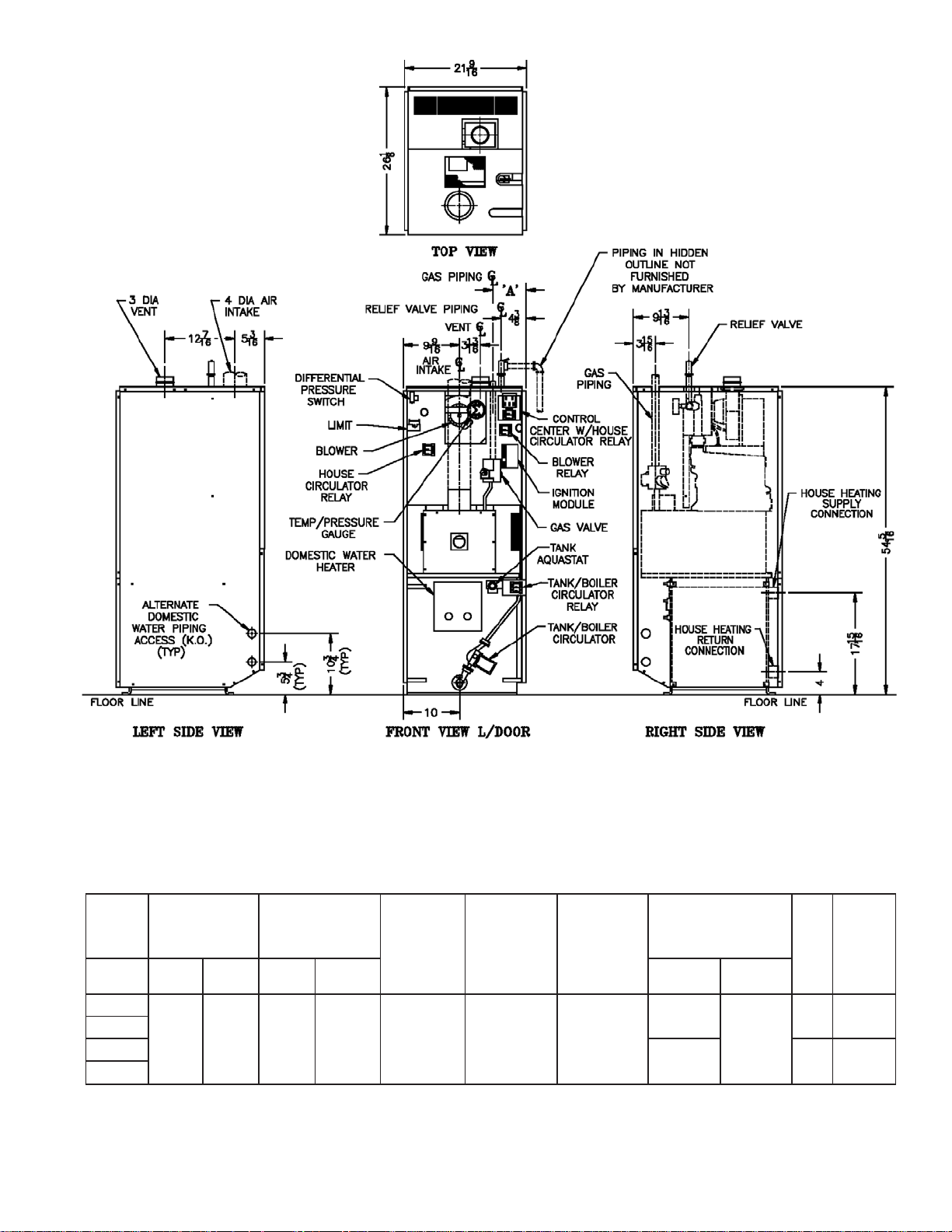
Figure 1: Dimensional Drawing
3
Page 4
I. Pre-Installation
GNINRAW
erofebsnoitcurtsnilladaerylluferaC
llawollofoteruliaF.reliobgnillatsni
esuacnacredroreporpnisnoitcurtsni
.htaedroyrujnilanosrep
A. Installation must conform to the requirements of the
authority having jurisdiction. In the absence of such
requirements, installation must conform to:
USA ANSI Z223.1, National Fuel Gas Code.
Where required by the authority having
jurisdiction, the installation must also conform to
ANSI/ASME CSD-1 Standard for Controls and
Safety Devices for Automatically Fired Boilers.
CANADA CAN/CGA B149.1 or .2 Installation Codes
for Gas Burning Appliances and Equipment,
and CSA C22.1 Canadian Electrical Code,
Part I.
B. Appliance is design certifi ed for installation on
combustible fl ooring. The boiler must not be installed
on carpeting.
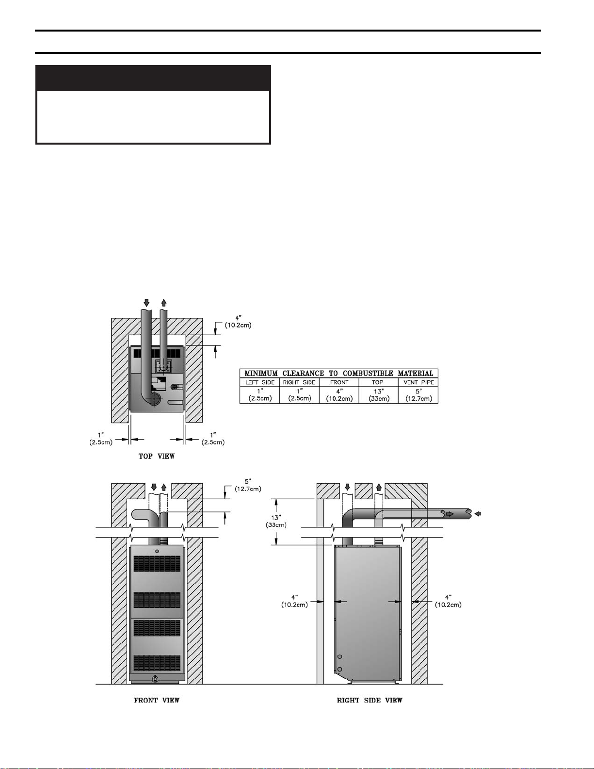
C. Provide clearance between boiler jacket and
combustible material in accordance with local fi re
ordinance. Refer to Figure 2 for minimum listed
clearance from combustible material. Recommended
service clearance is 24 inches from left side, right side,
front and rear. Service clearances may be reduced to
minimum clearances to combustible materials.
D. Install on level fl oor. For basement installation provide
concrete base if fl oor is not perfectly level or if water
may be encountered on fl oor around boiler.
E. Protect gas ignition system components from water
(dripping, spraying, rain, etc.) during boiler operation
and service (circulator replacement, condensate trap,
control replacement, etc.).
Figure 2: Minimum Clearances to Combustible Surfaces
4
Page 5
F. Provide combustion and ventilation air in accordance
with applicable provisions of local building codes, or
National Fuel Gas Code, ANSI Z223.1, Section 5.3, Air
for Combustion and Ventilation.
GNINRAW
rianoitalitnevdnanoitsubmocetauqedA
reporperussaotdedivorpebtsum
.noitsubmoc
II. Unpack Boiler
This boiler is equipped with a fan which produces an
induced draft through the unit. 100% of combustion air
is pulled in from outdoors and the fl ue gases are
exhausted to the outdoors through the intake air/vent
system. Refer to Section VI.
G. Do not install boiler where gasoline or other fl ammable
vapors or liquids, or sources of hydrocarbons (i.e.
bleaches, cleaners, chemicals, sprays, paint removers,
fabric softeners, etc.) are used or stored.
NOITUAC
.roolftsniagatekcaj
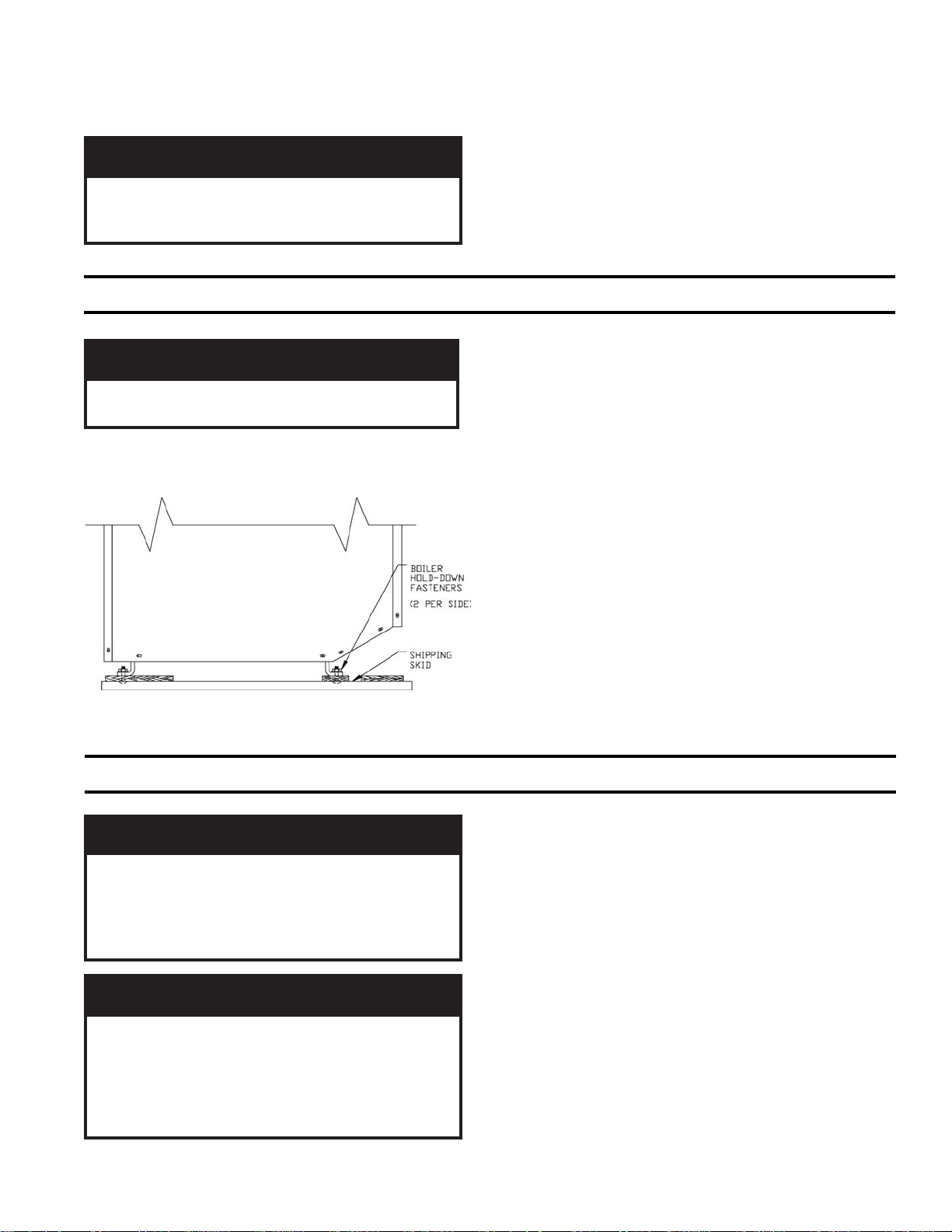
A. Move boiler to approximate installed position.
B. Remove all crate fasteners.
Figure 3: Removal From Skid
III. Water Piping and Trim
C. Remove outside container with all other inside
protective spacers and bracing. Save two of the
reliobpmubtonoD.reliobpordtonoD
wooden slats from the container sleeve for use in Steps
E and F.
D. Remove four (4) boiler hold-down fasteners. See
Figure 3.
E. Tilt the boiler to one side and slide a wooden slat under
the two nylon glides.
F. Tilt the boiler to the other side and slide another
wooden slat under the two nylon glides.
G. Slide the boiler forward or backward off the skid using
the two wooden slats as runners.
H. Move boiler to its permanent location.
NOITUAC
nitluseryamreliobepipylreporpoteruliaF
roreliobotegamaddnanoitareporeporpmi
.gnidliub
REDEEFRETAWCITAMOTUAESUTONOD
.RELIOBSIHTHTIW
NOITUAC
lliwretawreliobfonoitanimatnocnegyxO
reliobleetsdnanorifonoisorrocesuac
.eruliafreliobotdaelnacdna,stnenopmoc
tonseodytnarrawdradnatss'mahnruB
negyxoybdesuacsmelborprevoc
.retawreliobfonoitanimatnoc
A. Design and install boiler and system piping to
prevent oxygen contamination of boiler water.
Oxygen contamination sources are system leaks
requiring addition of makeup water, fi ttings, and
oxygen permeable materials in distribution system.
Eliminate oxygen contamination by repairing system
leaks, repairing fi ttings, and using nonpermeable
materials in distribution system.
B. Connect system supply and return piping to boiler.
See Figure 4. Also consult I=B=R Installation and
Piping Guides. Maintain a clearance between hot water
piping and combustible construction as required by
local codes. In the absence of local codes, ½" clearance
should be used. Note that a system circulator is
required and is not supplied with the Minuteman II.
5
Page 6
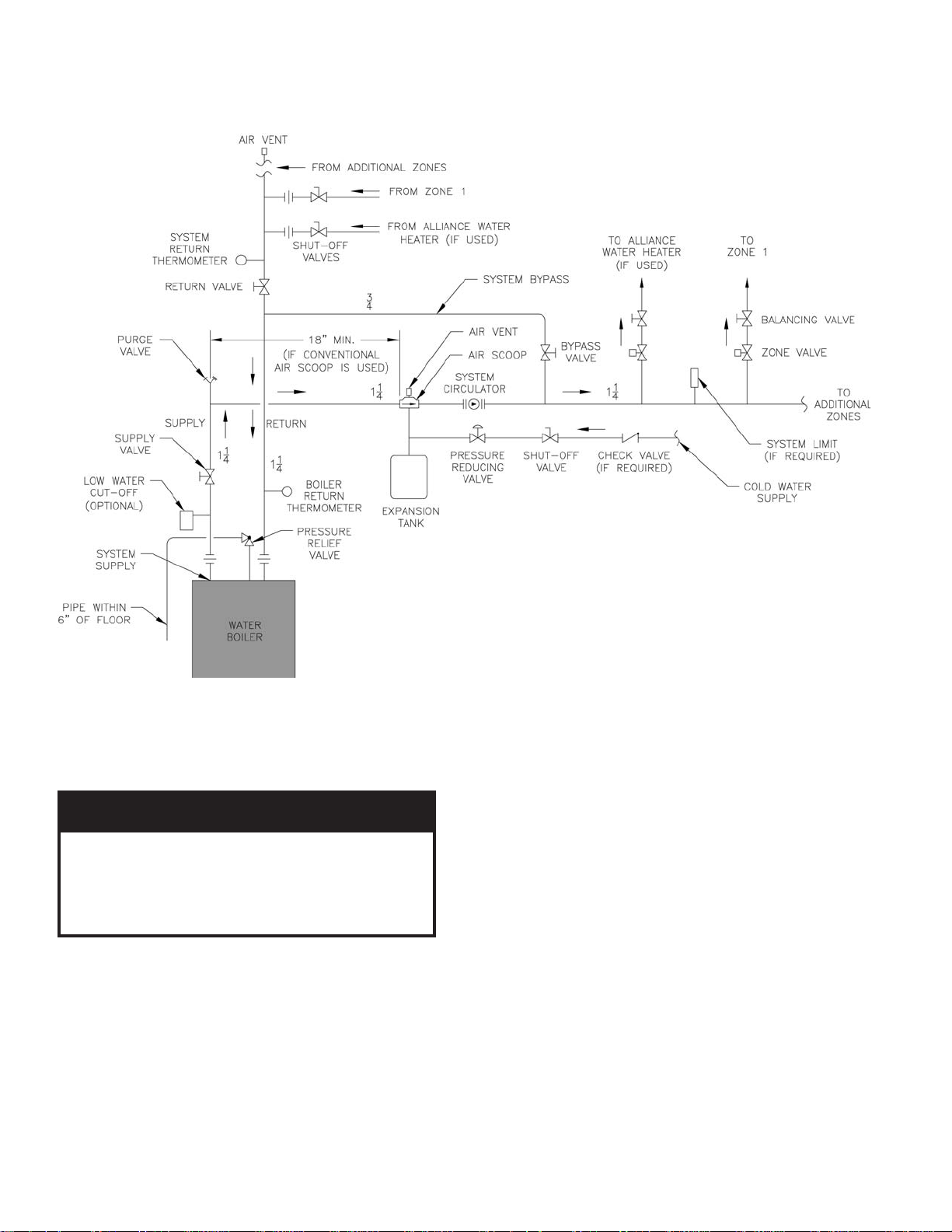
C. Install Safety Relief Valve. See Figure 4. Safety Relief
Valve must be installed with spindle in vertical position.
Installation of the relief valve must be consistent with
the ASME Boiler and Pressure Vessel Code, Section IV.
Figure 4: Recommended Water Piping for Zone Valve Zoned Heating Systems
GNINRAW
folaitnetopetanimileotroolfraendepip
ves
.sevlavffo-tuhsyna
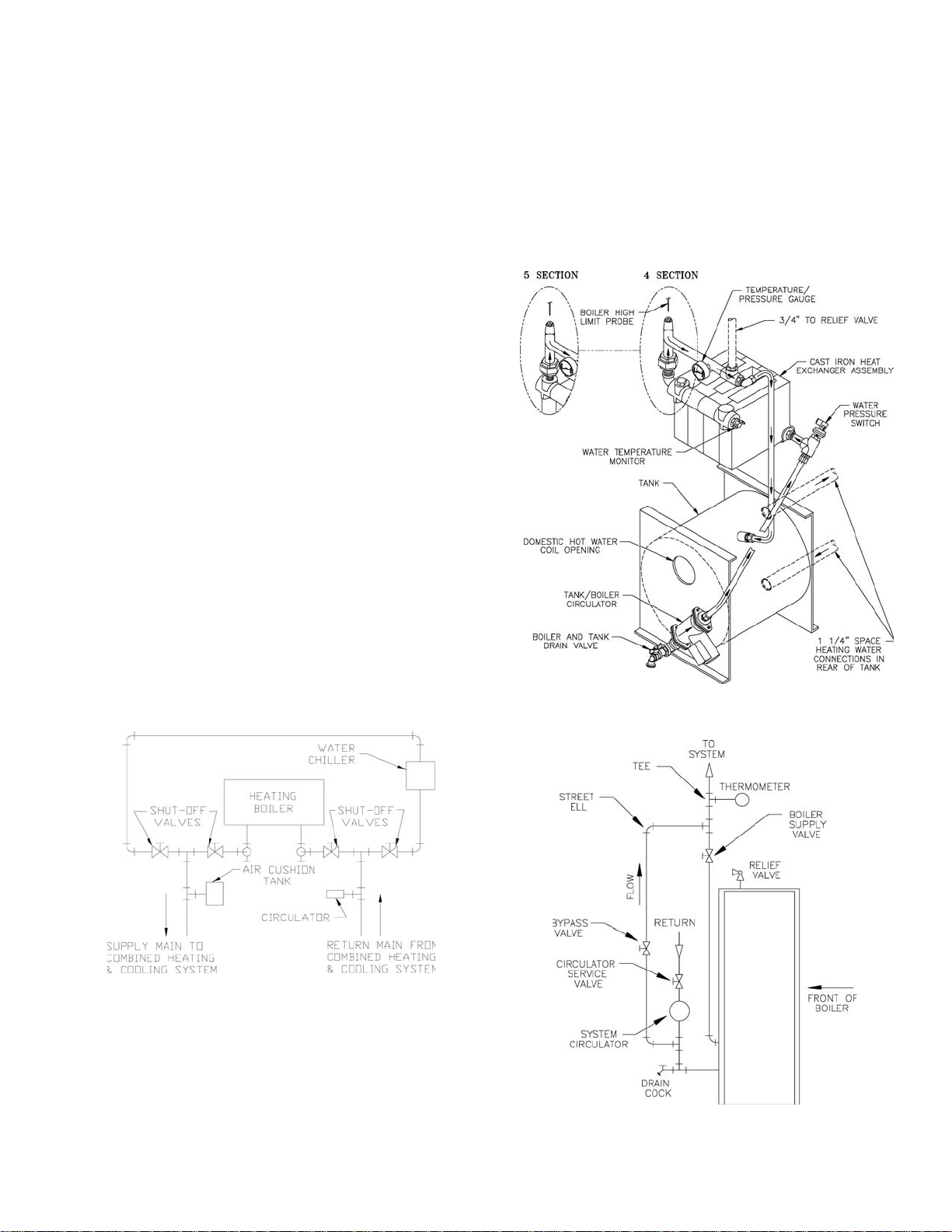
D. If boiler is used in connection with refrigeration
systems, boiler must be installed with chilled medium
piped in parallel with the heating boiler using
appropriate valves to prevent chilled medium from
entering boiler, see Figure 5. Also consult I=B=R
Installation and Piping Guides.
aeraynaniepiptonoD.snrubere
Refer to Figure 5a for a diagram of the water piping
system inside the Minuteman
ebtsumgnipipegrahcsidevlavfeilerytefaS
llatsnitonoD.ruccodluocgnizeerferehw
E. If boiler is connected to heating coils located in air
handling units where they may be exposed to
refrigerated air, boiler piping must be equipped with
fl ow control valves to prevent gravity circulation of
boiler water during operation of cooling system.
®
II's jacket.
F. Use a boiler bypass if the boiler is to be operated in a
system which has a large volume or excessive radiation
where low boiler water temperatures may be
encountered (i.e. converted gravity circulation system,
etc.).
6
Page 7
Install pipe tee between circulator and boiler return
along with second tee in supply piping as shown in
Figure 4. Bypass should be same size as the supply and
return lines with valves located in bypass and supply
outlet as illustrated in Figure 4 in order to regulate
water fl ow to maintain higher boiler water temperatures.
After the boiler is operational (reference Section VII.
System Start-Up) set by-pass and boiler supply valves
to half throttle position to start. Operate boiler until
system water temperature reaches normal operating
range.
Adjust valves to provide 180° to 200°F supply water
temperature. Opening the boiler supply valve will raise
system temperature, while opening the by-pass valve
will lower system supply temperature.
G. A hot water boiler installed above radiation level
must be provided with a low water cut-off device as
part of installation.
If a low water cut-off is required, it must be mounted in
the system piping above the boiler.
The minimum safe water level of a hot water boiler is
just above the highest water containing cavity of the
boiler; that is, a hot water boiler must be full of water to
operate safely.
It is required to perform a long term pressure test of the
hydronic system, the boiler should fi rst be isolated to
avoid a pressure loss due to the escape of air trapped in
the boiler.
To perform a long term pressure test including the
boiler, ALL trapped air must fi rst be removed from the
boiler.
A loss of pressure during such a test, with no visible
water leakage, is an indication that the boiler contained
trapped air.
H. Oil, grease, and other foreign materials which
accumulate in new hot water boilers and a new or
reworked system should be boiled out, and then
thoroughly fl ushed. A qualifi ed water treatment
chemical specialist should be consulted for
recommendations regarding appropriate chemical
compounds and concentrations which are compatible
with local environmental regulations.
Figure 5: Recommended Piping for Combination
Heating & Cooling (Refrigeration)
Systems
Figure 5a: Internal Water Piping System Diagram
I. After the boiler and system have been cleaned and
fl ushed, and before refi lling the entire system add
appropriate water treatment chemicals, if necessary, to
bring the pH between 7 and 11.
Figure 6: Recommended Bypass Piping
7
Page 8
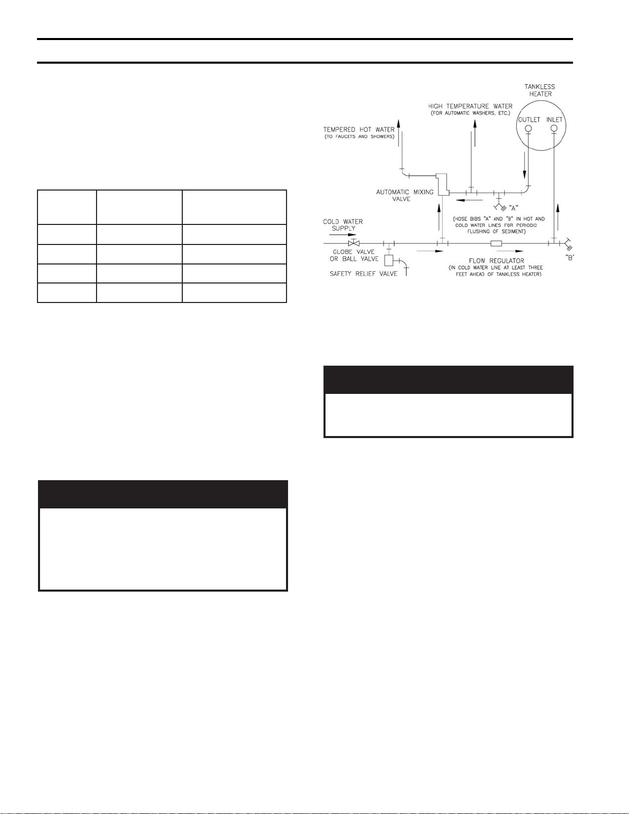
IV. Domestic Hot Water Performance and Piping
A. Domestic hot water ratings for the Minuteman
based two 5 minute draws with 10 minute recovery
period at 100°F average temperature rise. Refer to
Table 1 for ratings.
Table 1: Domestic Hot Water Ratings
RELIOB
LEDOM
07-4IIMM9.241
501-4IIMM1.361
501-5IIMM1.361
041-5IIMM3.381
WARDRETAW
)MPG(
B. Drain domestic water system.
1. Shut off cold water supply at main shutoff valve.
2. Open 1 or more system faucets to relieve pressure.
Open system drain valve, leaving faucets open to
relieve vacuum.
3. Disconnect exiting domestic hot water heating
system ( if applicable).
®
)ISP(
II are
PORDERUSSERP
Figure 7: Domestic Hot Water Piping
ECITON
ehtsaherutarepmetretawcitsemoD
erutarepmetderisedehtdeecxeotlaitnetop
.elcycgnitaehecapsagnirud
C. Connect hot water piping to ½" NPT outlet of heater.
See Figure 7.
GNINRAW
gnirepmet(evlavgniximcitamotuanallatsnI
ksirdiovaotteltuoretaehsselknatehtta)evlav
tohylevissecxeoteudgnidlacsrosnrubfo
ehtniatniamdnatsujdA.serutxiftaretaw
ehthtiwecnadroccanievlavgnixim
tcafunam
.snoitcurtsnis'reru
D. Connect cold water piping to ½" NPT inlet of heater.
See Figure 7.
E. Fill domestic hot water system.
1. Open all faucets to allow air to purge from heater
and piping.
2. Open domestic hot water shutoff valve (if used).
3. Open cold water inlet shutoff valve.
4. Purge air from domestic water system. Close
faucets.
5. Check system for leaks. Repair as necessary.
8
Page 9

V. Gas Piping
A. Size gas piping. Design system to provide adequate gas
supply to boiler. Consider these factors:
1. Allowable pressure drop from point of delivery to
boiler. Maximum allowable system pressure is ½
psig. Actual point of delivery pressure may be less;
contact gas supplier for additional information.
Minimum gas valve inlet pressure is stamped on the
rating label located in the boiler's vestibule
compartment.
2. Maximum gas demand. Table 2 lists boiler input
rate. Also consider existing and expected future gas
utilization equipment (i.e. cooking equipment).
3. Length of piping and number of fi ttings. Refer to
Table 3 for maximum capacity of Schedule 40 pipe.
Table 4 lists equivalent pipe length for standard
fi ttings.
Table 2: Rated Input
relioB
ledoM
rebmuN
07-4IIMM0782½
501-4IIMM50124½
501-5IIMM50124½
041-5IIMM04165½
larutaN
saG
etaRtupnI
]ruohrepteefcibuc[
saGPL
saG
noitcennoC
4. Specifi c gravity of gas. Gas piping systems for gas
with a specifi c gravity of 0.70 or less can be sized
directly from Table 3, unless authority having
jurisdiction specifi es a gravity factor be applied. For
specifi c gravity greater than 0.70, apply gravity
factor from Table 5. If exact specifi c gravity is not
shown choose next higher value.
For materials or conditions other than those listed
above, refer to National Fuel Gas Code, NFPA 54/
ANSI Z223.1, or size system using standard
engineering methods acceptable to authority having
jurisdiction.
B. Connect boiler gas valve to gas supply system.
1. Use methods and materials in accordance with local
plumbing codes and requirements of gas supplier. In
absence of such requirements, follow National Fuel
Gas Code, ANSI Z223.1.
2. Use thread (joint) compounds (pipe dope) resistant
to action of liquefi ed petroleum gas.
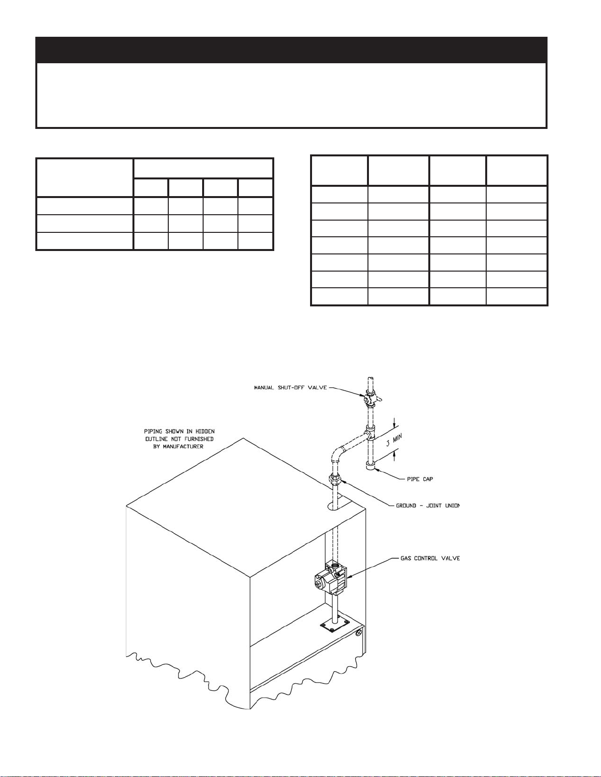
3. Install sediment trap, ground-joint union and manual
)sehcnI(eziS
shut-off valve upstream of boiler gas control valve
and outside of jacket. See Figure 8.
4. All above ground gas piping upstream from manual
shut-off valve must be electrically continuous and
bonded to a grounding electrode. Do not use gas
piping as grounding electrode. Refer to National
Electrical Code, ANSI/NFP A 70.
Table 3: Maximum Capacity of Schedule 40 Pipe in CFH For Gas Pressures of 0.5 psig or Less
htgneL
]teeF[
01231872025050,1571063086004,1
0229091053037021052564059
033725158209579002573077
043603154200528071023066
056551151204437151582085
0605501591004668310620
07646908107316521042094
08340907105375811022064
09044806102335011502034
001839705150305301591004
½¾ 1 ¼1½¾1¼1
porDerusserP.c.whcni3.0 porDerusserP.c.whcni5.0
35
9
Page 10
ECITON
neebevahlevelaesevobateef000,2nahtretaergsedutitlatanoitallatsniroftliubsreliobASU
ehtreplevelaesevobateef000,1reptnecrep4etartupnisagecuderotdecifiroyllaiceps
tceS,1.322ZISNA,edoCsaGleuFlanoitaN
.lebalgnitarehtno"H"xiffusrebmun
ecifiro'sreliobnaidanaC.FxidneppAdna2.1.8noi
ledomehtybelbaifitnedierasledomreliobedutitlahgiH.lebalgnitarehtnodetacidnisignizis
Table 4: Fitting Equivalent Lengths
eziSepiPlanimoN
gnittiF
½¾ 1 ¼1
llE°547.012.16.1
llE°096.11.26.25.3
)woblEsA(eeT1.31.42.59.6
C. Pressure test. The boiler and its gas connection must be
leak tested before placing boiler in operation.
1. Protect boiler gas control valve. For all testing over
½ psig, boiler and its individual shutoff valve must
be disconnected from gas supply piping. For testing
at ½ psig or less, isolate boiler from gas supply
piping by closing boiler's individual manual shutoff
valve.
Table 5: Specifi c Gravity Correction Factors
cificepS
ytivarG
05.001.103.170.1
55.040.104.140.1
06.000.105.100.1
56.069.006.179.0
07.039.007.149.0
57.009.0
08.078.0
noitcerroC
rotcaF
cificepS
ytivarG
2. Locate leaks using approved combustible gas
detector, soap and water, or similar nonfl ammable
solution. Do not use matches, candles, open fl ames,
or other ignition source.
noitcerroC
rotcaF
10
Figure 8: Recommended Gas Piping
Page 11
VI. Venting / Air Intake Piping
:swollofsaerasnoitcurtsnieseht
stnenopmoctnevfogniniojynA)1
saeltasevlovnitaht
enot
tnenopmoctnevssel-teksag
tnalaesehtseriuqersyawla
.noitacilppa
ehT)2
.tnenopmoc
ssel-teksagafodneelamef
seriuqersyawlatnenopmoctnev
ehtfosseldrager,dnabpmalca
tnevelamgnitamehtfongised
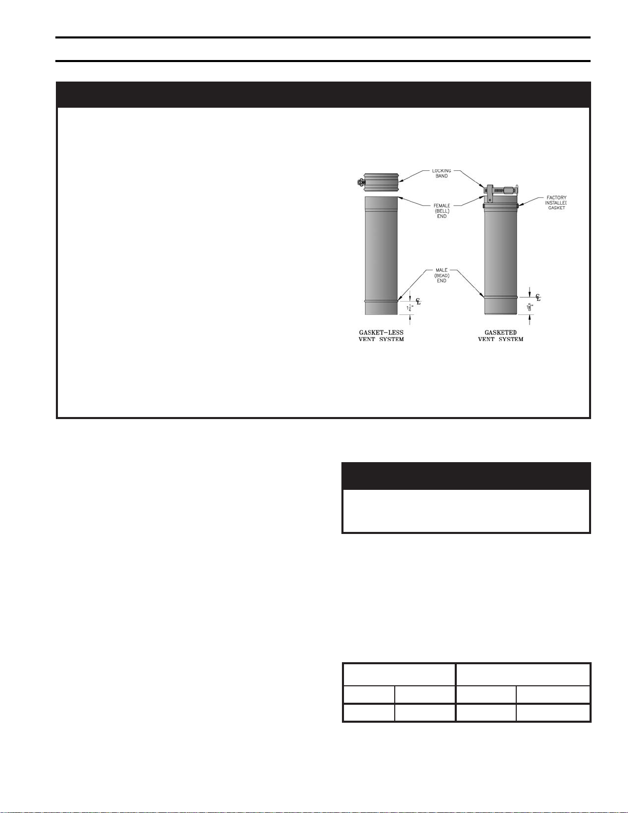
ECITON
hcaednanidesahpgnieberaAerugiFniwolebderutcipstnenopmocmetsystnevdeteksagehT
gnitnevssel-teksagdeilppusylsuoiverpehthtiwelbaegnahcretnisitnenopmoctnev
odyehtsa,niojotreisaednarekciuqyllarenegerastnenopmoctnevrewenehT.stnenopmoc
.dehcattaerasdnabpmalcriehtdnanoitacilppatnalaesehteriuqerton
adnatnenopmoctnevdeteksagatneveehtnI
-nocretniebtsumtnenopmoctnevssel-teksag
htiwdetaicossasnoitcurtsniehtwollof,detcen
f
oselpicnirpgnidiugowtehT.C01roB01erugiF
Figure A: Burnham Vent
.tnalaesfoebutecnuo
A. General Guidelines.
1. Vent system installation must be in accordance with
National Fuel Gas Code, ANSI Z223.1, Venting of
Equipment, or applicable provisions of local
building codes. Contact local building or fi re
offi cials about restrictions and installation inspection
in your area.
2. This appliance requires a Special Gas Vent. The
product is designed to use Burnham supplied
AL 29-4C® Stainless Steel vent system components.
The following manufacturer's offer similar AL 294C® components and are approved for use with this
product: Heat-Fab Inc. - Saf-T-Vent, Flex-L
International Inc. - Star-34, Protech Systems, Inc. FasNSeal™, and Z-Flex U. S., Inc. - Z-Vent. The
use of these alternate manufacturer's venting
systems will require adapters to connect to the
Burnham supplied vent connector and vent terminal.
These adapters are not supplied with this unit and
should be obtained from the supplier of the alternate
manufacturer's venting system. See Table 7 for
complete parts list.
.tnalaesdnadnabpmalcahtiwdeilppussitnenopmoctnevssel-teksaghcaE
GNINRAW
®
C4-92LA
3. Vent length restrictions are based on equivalent
length of vent pipe (total length of straight pipe plus
equivalent length of fi ttings). Maximum vent length
is listed in Table 6. Do not exceed maximum vent/
air intake lengths. Table 7 lists equivalent length for
fi ttings. Do not include Vent Terminal or Vent
Connector in equivalent feet calculation.
Table 6: Vent/Air Intake Length
).tF.viuqE(epiPtneV"3"4epiPekatnIriA).tF.viuqE(
.niM.xaM.niM.xaM
8078 07
.smetsystnevdesab
3enodnadnabpmalcenosniatnoctahtelbaliavasi,2036116rebmuntrap,tiKnoitisnarTtneVA
403,dezinavlaghtiwreliobsihtesutonoD
nonrehtoynaroleetssselniats613ro
11
Page 12
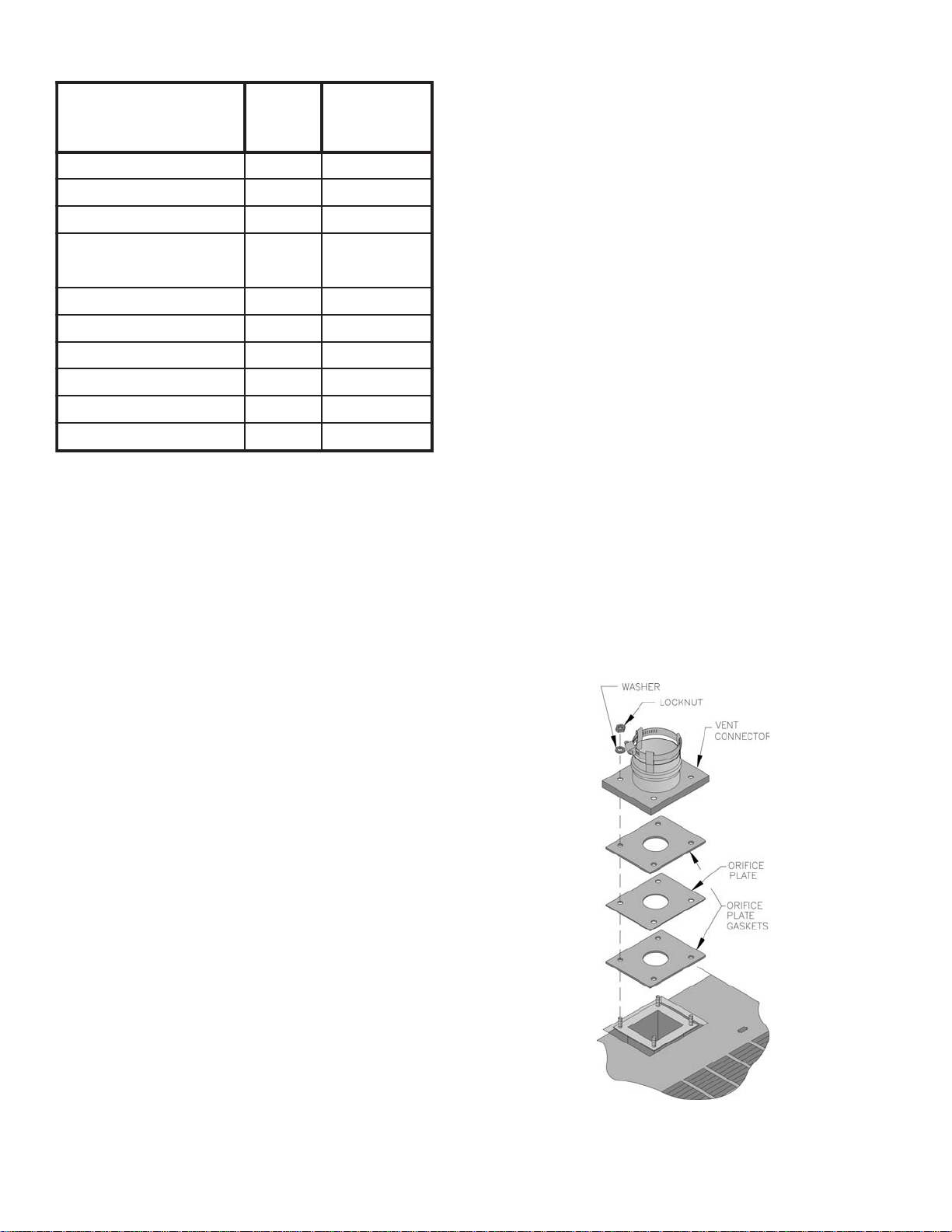
Table 7: Burnham Vent System Components
mahnruB
metsyStneV
tnenopmoC
tF1xepiP.aiD"3U69261181
tF3xepiP.aiD"3U89261183
tF5xepiP.aiD"3U00361185
elbatsujdAxepiP.aiD"3U9136118
woblE°09.aiD"3U49261185
woblE°54.aiD"3U29261185
eeTniarDlatnoziroH.aiD"3U2036118½
eeTn
iarDlacitreV.aiD"3U4036118½7
elbmihTllaWelgniS"36116118---
elbmihTllaWelbuoD"35116118---
mahnruB
traP
rebmuN
otlauqE
neLdellatsnI
4. Do not install venting system components on the
exterior of the building except as specifi cally
required by these instructions.
5. Thickness of exterior walls through which vent-air
intake system may be installed: Minimum: 3",
Maximum: 12".
B. Removal of Existing Boiler. For installations not
involving the replacement of an existing boiler, proceed
to Step C.
When an existing boiler is removed from a common
venting system, the common venting system is likely to
be too large for proper venting of the remaining
appliances. At the time of removal of an existing boiler,
the following steps shall be followed with each
appliance remaining connected to the common venting
system placed in operation, while the other appliances
remaining connected to the common venting system
are not in operation:
1. Seal any unused openings in the common venting
system.
2. Visually inspect the venting system for proper size
and horizontal pitch and determine there is no
blockage or restriction, leakage, corrosion, and other
defi ciencies which could cause an unsafe condition.
3. Insofar as is practical, close all building doors and
windows and all doors between the space in which
the appliances remaining connected to the common
venting system are located and other spaces of the
building. Turn on clothes dryers and any appliance
not connected to the common venting system. Turn
on any exhaust fans, such as range-hoods and
bathroom exhausts, so they will operate at maxi mum
speed. Do not operate a summer exhaust fan. Close
fi replace dampers.
4. Place in operation the appliance being inspected.
Follow the Lighting (or Operating) Instructions.
tnelaviuqE
epiPfoteeF
Adjust thermo stat so appliance will operate
continuously.
5. Test for spillage at the drafthood relief opening after
5 minutes of main burner operation. Use the fl ame
of a match or candle, or smoke from a cigarette,
cigar or pipe.
6. After it has been determined that each appliance
remain ing connected to the common venting system
htg
)46.1ot60.1(
properly vents when tested as outlined above, return
doors, win dows, exhaust fans, fi replace dampers and
any other gas burning appliance to their previous
conditions of use.
7. Any improper operation of the common venting
system should be corrected so the installation
conforms with the National Fuel Gas Code,
ANSI Z223.1 and/or CAN/CGA B149, Installation
Codes. When resizing any portion of the common
venting system, the common venting system
should be resized to approach the minimum size as
determined using the appropriate tables in Part 11 in
the National Fuel Gas Code, ANSI Z223.1 and/or
CAN/CGA B149, Installation Codes.
C. Install Vent Connector.
1. Remove vent connector from vent accessory carton.
2. Remove gaskets, orifi ce plate and hardware from
blower outlet fl ange.
3. Assemble orifi ce plate gaskets, orifi ce plate, and
vent connector. See Figure 9.
Figure 9: Vent Connector Installation
12
Page 13

4. Secure vent connector with washers and locknuts.
Do not overtighten.
D. Install Vent Pipe, General.
1. Plan venting system to avoid possible contact with
plumbing or electrical wires. Start at vent connector.
Work toward vent terminal.
2. Use non-combustible ¾ inch pipe strap to support
horizontal runs and maintain vent location and slope
while preventing sags in pipe. Do not restrict
thermal expansion or movement. Maximum support
spacing is 5 feet. Do not penetrate any part of the
vent system with fasteners.
3. Provide and maintain minimum 5 inch clearance to
combustible materials. Use double wall thimble
(Burnham Part No. 8116115) when penetrating
combustible wall. Other wall thimble manufacturers
are American Metal Products, Hart & Cooley, and
Metal Fab.
4. Once a vent pipe manufacturer and system is chosen
never mix and match vent systems.
5. If a non-standard length pipe is required:
The use of the adjustable length pipe (P/N
8116319U) is recommended to complete a nonstandard pipe length. This pipe requires a minimum
installed length of 12¾ inch and can adjust across a
7 inch gap up to a maximum of 19¾ inch long.
(Note for the adjustable pipe the installed length
should be measured from the centerline of the bead
on the male end of the fi rst pipe to the end of the
female pipe excluding the locking band of the
second pipe with a single gasket.) Only in the event
the adjustable length pipe is not suffi cient a standard
length pipe may be cut using the procedure outlined
below .
GNINRAW
.epiphtgnelelbatsujdarofsehcni¾91
.elbissopsiegakaelsageulffoksiR
Carefully cut pipe to length using a hacksaw with
minimum 32 teeth per inch or circular saw with
metal abrasive wheel. Remove male (bead) end
only – female (bell) end accepts next fi tting or pipe.
ECITON
e
.launamsihtnideificeps
6. Seal all Burnham Gasket-Less vent, Burnham mixed
vent (Gasket-Less and Gasketed) and fi eld cut joints
using Dow Corning Silastic 732 RTV, Dow Corning
Silastic 736 RTV, GE RTV106, Polybac #500 RTV,
Sil-bond RTV 4500 (Acetoxy) and Sil-bond RTV
6500. Do not use other adhesives or sealants.
E. Install Vent Pipe, Burnham Gasket-Less Vent System.
1. Procedure for Joining Burnham Gasket-Less Vent
Pipe and Fittings. See Figure 10A.
Figure 10A: Burnham Gasket-Less Vent Joint
a. Clean joints of pipe or fi ttings using an alcohol
pad to remove any dirt and grease.
b. Slip a locking band over female (bell) end of
pipe/fi tting.
c. Apply a continuous ¼ inch bead of sealant
around male end of joint no more than 1/8 inch
from end.
d. Align weld seams and use a slight twisting
motion to FULLY insert male end into female
end of joint. Ensure bead in male end rest against
the end of the female pipe.
e. Smooth sealant around joint for a continuous
seal. Reapply sealant if necessary.
fohtgneldellatsnimumixamdeecxereveN
rodelifdnaepiphtiwerauqsebtsumtuC
ylluferaC.gniniojerofebhtoomsdednas
htiwdnahybepiptucfossendnuorerusn
VTRhtiwtniojlaeS.gnillatsnierofebsevolg
F. Install Vent Pipe, Burnham Gasketed Vent System.
f. Slip the locking band over joint and align closest
bead in locking band with bead in male end of
pipe.
g. Tighten locking band by HAND with a 5/16" nut
driver until snug plus ¼ turn. DO NOT
SECURE JOINTS WITH SHEET METAL
SCREWS OR POP RIVETS. DO NOT
PUNCTURE THE VENT SYSTEM!
h. Once the installation is complete, operate
appliance and inspect all joints to ensure that fl ue
gases and/or liquid condensate will not escape.
1. Procedure for Joining Burnham Gasketed Vent Pipe
and Fittings. See Figure 10B.
a. Wipe the male end of each joint using an alcohol
pad to remove any dirt and grease.
13
Page 14

Figure 10B: Burnham Gasketed Vent Joint Detail
b. Align weld seams in pipes and use a slight
twisting motion to FULLY insert male end into
female end of joint. Ensure bead in male end of
pipe is below locking band and rest against the
end of the female pipe. Verify the factoryinstalled gasket is not dislodged or cut.
c. Tighten locking band by HAND with a 5/16" nut
driver until snug plus ¼ turn. DO NOT
SECURE JOINTS WITH SHEET METAL
SCREWS OR POP RIVETS. DO NOT
PUNCTURE THE VENT SYSTEM!
d. Once the installation is complete, operate
appliance and inspect all joints to ensure that fl ue
gases and/or liquid condensate will not escape.
G. Install Vent Pipe, Burnham Gasket-Less & Gasketed
Vent System.
1. Procedure for joining the male end of Burnham
Gasket-Less Vent with the female end of Burnham
Gasketed Vent. See Figure 10C.
Figure 10C: Burnham Gasket-Less Male and
Gasketed Female Vent Joint Detail
a. Clean the male end of each joint using an alcohol
pad to remove any dirt and grease.
b. Apply a continuous ¼ inch bead of sealant
around male end of joint no more than 1/8 inch
from end.
c. Align weld seams in pipes and use a slight
twisting motion to FULLY insert male end into
female end of joint. Ensure bead in male end of
pipe is below locking band and rest against the
end of the female pipe. Verify the factoryinstalled gasket is not dislodged or cut.
d. Smooth sealant around joint for a continuous
seal. Reapply sealant if necessary.
e. Tighten locking band by HAND with a 5/16" nut
driver until snug plus ¼ turn. DO NOT
SECURE JOINTS WITH SHEET METAL
SCREWS OR POP RIVETS. DO NOT
PUNCTURE THE VENT SYSTEM!
f. Once the installation is complete, operate
appliance and inspect all joints to ensure that fl ue
gases and/or liquid condensate will not escape.
2. Procedure for joining the female end of Burnham
Gasket-Less Vent with the male end of Burnham
Gasketed Vent. See Figure 10D.
Figure 10D: Burnham Gasket-Less Female and
Gasketed Male Vent Joint Detail
a. Clean joints of pipe or fi ttings using an alcohol
pad to remove any dirt and grease.
b. Slip a locking band over female (bell) end of
pipe/fi tting.
c. Apply a continuous ¼ inch bead of sealant
around male end of joint no more than 1/8 inch
from end.
d. Align weld seams in pipes and use a slight
twisting motion to FULLY insert male end into
female end of joint.
e. Smooth sealant around joint for a continuous
seal. Reapply sealant if necessary.
f. Slip the locking band over joint and align closest
bead in locking band with bead in male end of
pipe.
g. Tighten locking band by HAND with a 5/16" nut
driver until snug plus ¼ turn. DO NOT
SECURE JOINTS WITH SHEET METAL
SCREWS OR POP RIVETS. DO NOT
PUNCTURE THE VENT SYSTEM!
h. Once the installation is complete, operate
appliance and inspect all joints to ensure that fl ue
gases and/or liquid condensate will not escape.
H. Horizontal (Through Wall) Vent Installation.
1. Maintain minimum ¼ inch per foot slope in
horizontal runs. Position weld seams in vent pipes
in all horizontal runs at the top to avoid condensate
from lying on the seams.
14
Page 15

a. Recommended Installation: slope toward vent
terminal. See Figure 11.
b. Alternate Installation (where recommended
installation is not practical): slope toward boiler.
Horizontal vent drain tee (see Table 7 for part
number) required. See Figure 12.
NOITUAC
secafrusnomrofyamecidnaerutsioM
tneverpoT.lanimrettnevdnuora
doogniebdluohssecafrus,noitaroireted
etniap,delaes(riaper
).cted
2. Vent terminal location restricted per following:
a. Minimum 12 inches above grade or normally
expected snow accumulation level, or 7 feet
above grade if located adjacent to public
walkway. Do not install over public walkways or
areas where local experience indicates
condensate or vapor from Category III
appliances creates a nuisance or hazard .
b. Minimum 3 feet above any forced air inlet
located within 10 feet.
c. Minimum 1 foot below, 1 foot horizontally from,
or 1 foot above any door, openable window,
gravity air inlet, or building opening through
which fl ue gases could enter any building
(including adjacent buildings).
Figure 11: Recommended Horizontal Vent Installation
Figure 12: Alternate Horizontal Vent Installaltion
15
Page 16

d. Minimum 4 feet (6 feet in Canada) horizontally
from electric meters, gas meters, regulators, and
relief equipment.
e. Minimum 12 inches from overhang or corner.
3. Use double wall thimble when passing through
combustible outside wall (thimble use optional for
noncombustible wall). Insert thimble through wall
from outside. Secure outside fl ange to wall with
nails or screws, and seal OD, ID and vent holes with
sealant material. Install inside fl ange to inside wall,
secure with nails or screws, and seal with sealant
material.
4. For noncombustible wall when thimble is not used,
size opening such that female (bell) end with
locking band attached cannot pass through.
5. Join vent terminal to vent pipe. Locate vent terminal
between 3" and 6" from wall when joined to inside
vent piping. See Figure 13.
6. Insert vent pipe through thimble/opening from
outside and join to vent system. Apply sealant
between vent pipe and opening/thimble to provide
weathertight seal.
Figure 15: Vent/Air Intake Terminal Relationship
Horizontal (thru wall) or Vertical (thru roof)
Figure 13: Horizontal Vent Pipe Wall Penetration
I. Vertical (Through Roof) Vent Installation
1. Install vertical vent drain tee (see Table 7 for part
number). See Figure 16. Attach tee directly to
elbow or horizontal pipe from elbow.
2. Install condensate drain line. Use 3/8 inch i.d. high
temperature fl exible tubing such as silicone rubber
or EPDM. See Figure below.
a. Form condensate trap with 6 inch diameter loop.
Secure loop with plastic cable tie. Fill with
water.
Figure 14: Horizontal Air Intake Pipe Wall
Penetration
16
Page 17

Figure 16: Vertical Vent Installation
b. Secure to vertical vent tee with hose clamp or
plastic cable tie.
c. Run condensate drain line to fl oor drain or
condensate pump. Condensate disposal must be
acceptable to authority having jurisdiction.
3. Slope horizontal runs minimum ¼ inch per foot.
Slope toward vertical vent drain tee. Position weld
seams in vent pipes in all horizontal runs at the top
to avoid condensate from lying on the seams.
4. Install fi restops at fl oor and ceiling where vent
passes through fl oor, ceiling, or framed wall. The
fi restop must close the fl oor or ceiling opening
between vent pipe and structure. Firestop
manufacturers are Air-Jet, American Metal Products,
Metal-Fab, and Simpson Dura-Vent.
5. Enclose vent passing through unoccupied or
occupied spaces above the appliance with materials
having a fi re resistance rating at least equal to the
rating of adjoining fl oor or ceiling. Maintain 5 inch
minimum clearance to combustible materials. Note:
For one-or two-family dwellings fi re resistance
rating requirement may not need to be met, but is
recommended.
6. Whenever possible install vent straight through roof.
Refer to Figure 17 if offset is necessary. Maintain 5
inch minimum clearance to combustible materials.
7. Install Vent Terminal. See Figure 18.
a. Locate roof opening to allow vertical vent
penetration. Size opening to maintain 5 inch
minimum clearance from combustible materials.
b. Vertical venting requires use of roof fl ashing
(available from Burnham - P/N 8116250) and
storm collar (available from Burnham - P/N
8116251) to prevent moisture from entering the
structure.
c. Extend vent pipe to maintain minimum vertical
and horizontal distance of 12 inches from roof
surface. Allow additional vertical distance for
expected snow accumulation. Provide brace as
required. Refer to Figure 18.
d. Install storm collar on vent pipe immediately
above roof fl ashing. Apply Dow Corning
Silastic 732 RTV Sealant between vent pipe and
storm collar to provide weathertight seal..
e. Attach Vent Terminal.
J. Install Air Intake Pipe.
1. Locate air intake termination on the same wall or
roof location as the vent termination if possible, to
prevent nuisance boiler shutdowns. However, boiler
Figure 17: Attic Offset
Figure 18: Vertical Vent Termination
Extend Vent/Air Intake Piping to maintain minimum vertical ("X") and minimum horizontal ("Y") distance
of twelve (12) inches from roof surface. Allow additional vertical ("X") distance for expected snow
Figure 19: Vertical Air Intake Termination
17
Page 18

may be installed with vertical venting and sidewall
combustion air inlet if installation conditions do not
allow alternate arrangement.
2. Use 4 inch diameter single wall metal pipe, fi ttings,
fi restop(s), roof fl ashing and storm collar available
at most heating distributors.
3. Start at air intake connector. Work toward air intake
terminal.
VII. Electrical
4. Maintain minimum of ¼ inch per foot slope in
horizontal runs to air intake terminal. Slope down
toward air intake terminal.
5. Seal all joints gas-tight, using silicone caulk or selfadhesive aluminum tape.
6. Install air intake terminal. See Figures 14 and 19.
A. General. Install wiring and ground boiler in accordance
with requirements of authority having jurisdiction, or in
absence of such requirements the National Electrical
Code, ANSI/NFPA 70, and/or the CSA C22.1 Electric
Code.
B. Install thermostat. Locate on inside wall
approximately 4 feet above fl oor. Do not install on
outside wall, near fi replace, or where infl uenced by
drafts or restricted air fl ow, hot or cold water pipes,
lighting fi xtures, television, or sunlight. Allow free air
movement by avoiding placement of furniture near
thermostat.
C. Wire thermostat. Provide Class II circuit between
thermostat and boiler. Set thermostat heat anticipator to
0.6 amps. See Figure 20.
D. Wire boiler. Boiler is rated for 120 VAC, 60 hertz, less
than 12 amperes. A separate electrical circuit must be
run from the main electrical service with an overcurrent device/disconnect in the circuit. A service
switch is recommended and may be required by some
local jurisdictions. Connect circuit to black and white
wires and green ground screw. See Figure 20.
18
Figure 20: Wiring Diagram
Page 19

VIII. System Start-up
A. Safe operation and other performance criteria were
met with gas manifold and control assembly provided
on boiler when boiler underwent tests specifi ed in
American National Standard for Gas-Fired LowPressure Steam and Hot Water Boilers, ANSI Z21.13.
B. FILL ENTIRE HEATING SYSTEM WITH WATER
and vent air from system. Use the following procedure
on a Series Loop System equipped with zone valves.
(See Figure 4).
1. Close isolation valve in boiler supply piping.
2. Isolate all circuits by closing zone valves or
balancing valves.
3. Attach a hose to hose bib located just below
isolation valve in boiler supply piping. (Note Terminate hose in fi ve gallon bucket or at a suitable
fl oor drain or outdoor area).
4. Starting with one circuit, open zone valve.
5. Open hose bib.
6. Open manual fi ll valve (Make-up water line should
be located directly above isolation valve in boiler
supply piping).
7. Allow water to overfl ow from bucket until discharge
from hose is bubble free for 30 seconds.
8. Open zone valve to the second zone to be purged,
then close the fi rst. Repeat this step until all zones
have been purged, but always have one zone open.
At completion, open all zone valves.
9. Close hose bib, continue fi lling the system until the
pressure gauge reads between 12 and 15 psi. Close
fi ll valve.
GNINRAW
.reliob
10. Open isolation valve in boiler supply piping.
11. Remove hose from hose bib.
C. Prepare to check operation.
sihthtiwevlavllifcitamotuanallatsniTONOD
1. Obtain gas heating value (in BTU per cubic foot)
from gas supplier.
2. Connect manometer to pressure tap on gas valve.
Use 1/8 NPT tapping provided.
3. Temporarily turn off all other gas-fi red appliances.
Figure 21: Sequence of Operation
19
Page 20

Figure 22: Operating Instructions
D. Follow Operating Instructions to place boiler in
operation. See Figure 22.
E. Sequence of Operation. See Figure 21. If boiler fails
to operate properly, see Troubleshooting Tree on pages
26-27.
F. Check pilot burner fl ame. See Figure 24. Flame
should be steady, medium hard blue enveloping 3/8 to
½ inch of sensing probe.
20
G. Check main burner fl ame. See Figure 23. Flame
should have clearly defi ned inner cone with no yellow
tipping. Orange-yellow streaks should not be confused
with true yellow tipping.
H. Check thermostat operation. Raise and lower
temperature setting to start and stop boiler operation.
I. Check domestic hot water (tank) aquastat operation.
Raise and lower temperature setting to start and stop
boiler operation. Tank aquastat should be set at least
Page 21

Figure 23: Main Burner Flame
Figure 24: Pilot Burner Flame
20°F below boiler high limit setting to allow tank water
to reach desired temperature before boiler water reaches
the high limit setting.
J. Ignition system safety device test. Disconnect ignitor/
sensor cable from Terminal 9 (SPARK). Gas valve
should close and pilot and main burners should
extinguish.
K. Check water pressure switch.
1. Adjust thermostat to highest setting.
2. Connect hose to drain valve and run to bucket or
fl oor drain. With boiler operating, partially open
drain valve and slowly drain boiler.
3. Main burners and pilot burner will extinguish and
blower stop when water pressure drops below 10
psi. Verify limit, thermostat or other controls have
not shut off boiler.
4. Close drain valve.
5. Adjust thermostat to lowest setting. Refi ll boiler.
L. Check Boiler High Limit.
1. Adjust thermostat to highest setting.
2. Observe temperature gauge. When temperature is
indicated, adjust limit to setting below observed
temperature. Main burners and pilot burner should
extinguish, and blower stop.
3. Adjust limit to setting above observed temperature.
Ignition sequence should begin.
4. Adjust thermostat to lowest setting. Adjust limit to
desired setting, at least 20°F above the tank aquastat
setting.
M. Adjust gas input rate to boiler.
1. Adjust thermostat to highest setting.
2. Check manifold gas pressure. Pressure should be
stamped on the rating label located in the boiler's
vestibule compartment. Adjust gas valve pressure
regulator as necessary (turn adjustment screw
counterclockwise to decrease manifold pressure, or
clockwise to increase manifold pressure). If pressure
cannot be attained, check gas valve inlet pressure. If
less than minimum indicated on the boiler's rating
label, contact gas supplier for assistance.
3. Clock gas meter for at least 30 seconds. Use Table 9
to determine gas fl ow rate in Cubic Feet per Hour.
21
Page 22

4. Determine Input Rate. Multiply gas fl ow rate by gas
heating value.
Table 9: Gas Flow Rate in Cubic Feet per Hour
5. Compare measured input rate to input rate stated on
rating plate.
a. Boiler must not be overfi red. Reduce input rate
by decreasing manifold pressure. Do not reduce
more than 0.2 inch w.c. If boiler is still overfi red,
contact your Burnham distributor or Regional
Offi ce for replacement Gas Orifi ces.
b. Increase input rate if less than 98% of rating
plate input. Increase manifold gas pressure no
more than 0.2 inch w.c. If measured input rate is
still less than 98% of rated input:
i. Remove Main Burners per procedure in
Section IX: Service.
ii. Remove gas orifi ces. Drill one (1) drill size
larger (drill size is stamped on orifi ce, or see
Key No. 4C in Section X: Repair Parts).
iii. Reinstall gas orifi ces and main burners.
Measure input rate.
6. Recheck Main Burner Flame.
sdnoceS
enOrof
noituloveR
0306021042
2365311522
4335601212
6305001002
837459981
045409081
243468271
441428461
649387751
847357051
056327441
255396831
453376331
652346921
flaH-enO
.tF.uC
enO
.tF.uC
laiDreteMsaGfoeziS
owT
.tF.uC
7. Return other gas fi red appliances to previous
conditions of use.
N. Review User's Information Manual and system
operation with owner or operator.
851326421
060306021
22
Page 23

IX. Service
A. General. Inspection and service should be conducted
annually. Turn off electrical power and gas supply while
conducting service or maintenance. Follow instructions
TO TURN OFF GAS TO APPLIANCE. See Figure 22.
NOITUAC
nehwnoitcennocsidotroirpseriwllalebaL
esuacnacsrorregniriW.slortnocgnicivres
yfireV.noitareposuoregnaddnareporpmi
.gnicivresretfanoitareporeporp
B. Inspect domestic hot water coil gasket for water
leakage. Tighten nuts or replace gasket if leakage is
evident.
C. Low water cut-off (if so equipped).
1. Float Type
a. Monthly Blowoff. During the heating season, if
an external fl oat type low water cut-off is on the
boiler, the blow off valve should be opened once
a month (use greater frequency where conditions
warrant), to fl ush out the sediment chamber so
the device will be free to function properly.
b. Annual Service. Float type low water cutoffs
should be dismantled annually by qualifi ed
personnel, to the extent necessary to insure
freedom from obstructions and proper
functioning of the working parts. Inspect
connecting lines to boiler for accumulation of
mud, scale, etc., and clean as required. Examine
all visible wiring for brittle or worn insulation
and make sure electrical contacts are clean and
that they function properly. Give special
attention to solder joints on bellows and fl oat
when this type of control is used. Check fl oat for
evidence of collapse and check mercury bulb
(where applicable) for mercury separation or
discoloration.
2. Probe Type (Annual Service). Probe type LWCO
should be removed once a year, examined and
cleaned of any dirt accumulations to assure proper
operations. Do not attempt to repair mechanisms in
the fi eld. Complete replacement mechanisms,
including necessary gaskets and installation
instructions, are available from the manufacturer.
D. Vent/Air Intake System. Inspect for obstructions, soot
accumulation, proper support, and deterioration of pipe,
fi ttings, and joints.
1. Clean terminal screens. Terminals must be free of
obstruction, undamaged, with screens securely in
place.
2. Terminal and wall thimbles (if used) must be
weathertight.
3. Pipe must be full round shape, and show no damage
from impact or excessive temperature.
4. Pipe must be supported at minimum 5 foot intervals
and must not sag.
5. All vent joints must be secure and watertight.
6. All air intake joints must be secure and airtight.
Horizontal vent tee drain (if used) must have
minimum 6 inch trap and allow condensate to fl ow
freely. To Clean:
a. Disconnect drain tube from drain fi tting.
b. Flush drain tube with water. Fill trap with water.
c. Securely fasten drain tube to drain fi tting,
providing gas-tight and watertight seal.
7. If pipe must be disassembled for removal of
obstructions or resealing of joint:
a. Remove locking band (vent pipe only).
b. Break skin of sealant with utility knife. Do not
cut or score pipe.
c. Pull pipe from fi tting.
d. Clean pipe and fi tting of all cured sealant.
e. Join pipe and fi tting as described in Section VI:
Venting/Air Intake Piping.
E. Boiler Flue Passages. Inspect for blockage or soot
accumulation.
1. Remove Main Burners. See Figure 25.
a. Remove jacket front door.
b. Remove combustion air enclosure cover.
c. Remove Burner Access Panel by lifting up and
out.
d. Disconnect Ignitor/Sensor Wire from pilot
burner.
e. Mark location of Main Burner with Pilot Bracket
on gas manifold.
f. Remove External Hitch Pin Clips.
g. Hold Main Burner on throat. Lift slightly while
pushing toward rear of boiler to disengage from
Burner Tray and to clear Gas Orifi ce. Pull Main
Burner from combustion chamber.
2. Remove four (4) locknuts securing vent connector.
23
Page 24

See Figure 9. Disconnect vent connector and vent
pipe from blower outlet.
5. Install main burners by reversing procedure to
remove burners.
3. Remove Jacket Top Panels.
4. Disconnect Red and Black Silicone Tubing from
Canopy. Pull tubing through Blower Access panel
into vestibule.
5. Disconnect wiring harness from Blower Motor.
6. Remove Canopy/Blower Assembly.
a. Remove four (4) machine screws securing
canopy to heat exchanger.
b. Remove ceramic fi ber gasketing from top of heat
exchanger.
c. Pry canopy from boiler sections.
7. Inspect fl ue passages. Clean with fl ue brush. See
Figure 25.
8. Inspect heating surface in combustion chamber.
Clean with straight handle wire brush.
9. Replace Canopy/Blower Assembly and seal using
ceramic fi ber gasketing. Refer to Key No. 2 in
Repair Parts Section for quantity and part number.
10. Connect Silicone Tubing between Pressure Fittings
on Canopy Assembly and Pressure Switch. See
Figure 26.
11. Install Jacket Top Panels.
12. Connect vent system. See Figure 9.
13. Connect Blower Motor Wiring Harness.
F. Main Burners and Combustion Chamber.
1. Vacuum combustion chamber. Exercise care - do
not damage base insulation.
2. Clean main burners. Brush top of burners with soft
bristle brush. See Figure 25. Vacuum to remove any
dirt and lint.
a. Pilot burner must be installed in original
location. See Table 10.
b. Main burners must be properly secured in burner
tray slot at rear of combustion chamber and over
gas orifi ce with hitch pin in place. See Figure 25.
c. Burner access panel must be securely in place.
d. Verify that Combustion Air Diffuser is securely
in place.
e. If Flame Roll-out Switch wires were
disconnected, they must be reconnected.
f. Air Intake Box Cover must be installed.
G. Check operation. Follow steps C through L from
Section VIII: System Start-up.
H. Procedure for Measuring Fan Differential Pressure.
(See Figure 27).
1. With boiler off, remove gray and black hoses at
differential pressure switch.
2. With tees, connect water manometer as shown with
additional tubing.
3. Start boiler and read pressure on manometer when
boiler water temperature reaches operating
temperature. Refer to Table 11 for minimum
readings.
NOTE: If switch drops-out before boiler reaches
temperature or if differential pressure readings are
below minimums shown in Table 11, check for
cracks in hoses or contact your nearest Burnham
representative.
4. Stop boiler, remove manometer and reconnect hoses
to pressure switch. See Figure 26.
I. Lubrication
3. Vacuum tip of pilot burner.
4. Check gas orifi ces for lint and dirt. Clean as
necessary.
24
There are no parts requiring lubrication on the part of
the Service Technician or the User. Circulator bearings
are water lubricated. Combustion blower motor uses
sealed bearings.
Page 25

Figure 25: Burner and Flueway Cleaning
25
Page 26

Figure 26: Silicone Tubing Assembly
Table 10: Pilot Burner Location
relioB
ledoM
07-411MM
&
501-411MM
501-511MM
&
041-511MM
.reliob
34&3
45&4
htiwrenruBniaM
*tekcarBtoliP°06
Figure 27: Differential Pressure Measurement
detacoLrenruBtoliP
*srenruBniaMneewteB
fotnorfmorfdeweivsathgirottfelderebmunsrenrubniaM*
Table 11: Differential Pressure Switch Settings
RELIOB
LEDOM
07-4IIMMcw"08.0
501-4IIMMcw"08.0
501-5IIMMcw"96.0
041-5IIMMcw"96.0
MUMINIM
ERUSSERP
26
Page 27

noitamrofnIytefaStcudorPtnatropmI
tcudorPrebiFcimareCyrotcarfeR
Warning:
This product contains refractory ceramic fi bers (RCF). RCF has been
classifi ed as a possible human carcinogen. After this product is fi red, RCF
may, when exposed to extremely high temperature (>1800F), change into a
known human carcinogen. When disturbed as a result of servicing or repair,
RCF becomes airborne and, if inhaled, may be hazardous to your health.
AVOID Breathing Fiber Particulates and Dust
Precautionary Measures:
Do not remove or replace previously fi red RCF (combustion chamber
insulation, target walls, canopy gasket, fl ue cover gasket, etc.) or attempt
any service or repair work involving RCF without wearing the following
protective gear:
1. A National Institute for Occupational Safety and Health
(NIOSH) approved respirator
2. Long sleeved, loose fi tting clothing
3. Gloves
4. Eye Protection
• Take steps to assure adequate ventilation.
• Wash all exposed body areas gently with soap and water after
contact.
• Wash work clothes separately from other laundry and rinse washing
machine after use to avoid contaminating other clothes.
• Discard used RCF components by sealing in an air tight plastic bag.
First Aid Procedures:
• If contact with eyes: Flush with water for at least 15 minutes.
Seek immediate medical attention if irritation persists.
• If contact with skin: Wash affected area gently with soap and
water. Seek immediate medical attention if irritation persists.
• If breathing diffi culty develops: Leave the area and move to a
location with clean fresh air. Seek immediate medical attention
if breathing diffi culties persist.
• Ingestion: Do not induce vomiting. Drink plenty of water. Seek
immediate medical attention.
27
Page 28

282930
Page 29

Page 30

X. Repair Parts
All Minuteman® II Repair Parts may be obtained through your local Burnham Wholesale distributor.
Should you require assistance in locating a Burnham Distributor in your area, or have questions regarding the availability of Burnham products or repair parts, please contact Burnham Customer Service at (717) 481-8400 or Fax (717) 481-8408.
rebmuNtraP]ytitnauQ[
.oNyeKnoitpircseD
07-4IIMM501-4IIMM501-5IIMM041-5IIMM
.1ylbmessAregnahcxEtaeH
24040716]1[2
ylbmessArewolB/yponaC.2
A2yponaC44040116]1[34040116]1[35040116]1[45040116]1[
B21013-2607#ocsaF,rewolB 5171116]1[
C2rotinoMeulF 22606108]1[
D2rotcennoCtneV 11.oNyeKeeS
E2teltuOnaF,etalPecifirO55040117]1[65040117]1[75040117]1[85040117]1[
F2)B2/wdedul
G2)B2/wdedulcni(gnitnuoMrewolB,teksaG 9406028]1[
H2gnoL"22x.D.I"61/3,gnibuT
J2gnoL"81x.D.I"61/3,gnibuTenociliS )htgneLyficepS(7006109
K2803A#reywD,gnit
L242-"8/3,lenaPleetSxeH,tuN 67406808]1[
M2"8/3talF,rehsaW 65606808]1[
N2.gl"1x02-"
P2detalP,EAS,"4/1talF,rehsaW 33606808]21[
enociliS )htgneLyficepS(6006109
cni(teltuOnaF,teksaG 5306028]2[
tiFerusserPcitatS 756228]2[
4/1,.dHxeH,wercSpaC 85316808]4[
5040716]1[
Q202-"4/1stuNkcoL 65406808]4[
R2)B2/
wdedulcni(02-"4/1,xeHssarB,tuN 42406808]4[
)detcipedton(gniteksaGtlefareC.3
regnahcxEtaeHotyponaC
6106027]1[
Page 31

313233
Page 32

Page 33

yeK
.oN
noitpircseD
07-4IIMM501-4IIMM501-5IIMM041-5IIMM
ylbmessAesaB.3
A3)noitalusnIo/w(repparWesaB 134040817]1[135040817]1[
1A3noitalusnIediSthgiR&tfeLesaB 42040027]2[
rebmuNtraP]ytitnauQ[
2A3noitalus
B3)dehcattanoitalusni(ylbmessAetalPesaB 64040816]1[65040816]1[
C3yarTrenruB
D3
1D3le
2D3reniateRsneLtroPnoitavresbO 9106817]1[
3D3teksaGsneLtroP
4D3sneLtroPnoitavresbO 2806208]1[
E3ylbmessAlenaPsseccArenruB 54040126]1[55040126]1[
1E
3lenaPsseccArenruB 114040127]1[115040127]1[
2E3tekcarBgnitnuoM/whctiwStuO-lloRemalF 0606106]1[
F3resuffiDriAn
G3)dehcattanoitalusni(ylbmessAlenaPtnorFesaB 44040816]1[45040816]1[
H3laeSdl
J3laeSdlofinaM,teksaG 2040818]1[
nIraeResaB 22040027]1[32040027]1[
44040127]1[45040127]1[
ylbmessAlenaPtnorFerusolcnErenruB
)4D3urht1D3sedulcni(
naPtnorFerusolcnErenruB 124040127]1[125040127]1[
noitavresbO 9306028]2[
oitsubmoC 54040127]1[55040127]1[
ofinaM,etalPgnikcaB 01040817]1[
64040126]1[65040126]1[
K3)dehcattanoitalusni(lenaPpoTerusolcnEren
M3seriWSRF,teksaG 3040818]1[
N3.gL.tF01x"2x"
P3.gL.tF01x"1x"8/1,teksaGepaTssalgrebiF 4006026]1[
Q3.gL"2/1x8#,wercSlate
R3.gL"2/1x02-"4/1,wercSgnippaT-fleS 00706808]01[
S3.gL"4/1-1x81-"61/5,wercSgnippaT-fleS
U381-"61/5,tuNkcoL 46406808]4[
ruB 44040126]1[45040126]1[
L3teksaGeriWSRF,etalPgnikcaB 2006907]1[
2/1,teksaGrebiFcimareC 2006026]1[
MteehS 00006808]02[
T3talF"61/5,rehsaW 10606808]4[
71706808]4[
Page 34

34
Page 35

yeK
.oN
noitpircseD
07-4IIMM501-4IIMM501-5IIMM041-5IIMM
rebmuNtraP]ytitnauQ[
A4evlaVsaG
B4dlofinaMsaG 1404022
larutaN
niaM
C4
D4pilCniP
E4.gL"03x.D.O"8/1,gnibuTtoliP 0116328]1[
F42-308493#llewyenoH,elbaCrosneS/noitingI 12
G4
H4tekcar
J4tekcarBtoliPsselrenruBsaGniaM 5116328]4[5116328]6[
K4.gL"61/3x23-01#,werc
renruB
secifirO
hctiH406228]5[406228]7[
toliP
ylbmessA
SenihcaM 00806808]2[
saG
75#656228]5[------------
PL
BtoliP/wrenruBsaGniaM 6116328]1[
0006C4028RVllewyenoH).taN( 67106618]1[
8106C4028RVllewyenoH)PL(08106618]1[A/N
8]1[15040228]1[
)wolleY(llirD94#556228]5[----556228]7[----
)deR(llirD34#----4362
)egnarO(llirD44#------------046228]7[
)kcalB(45#----536228]5[--------
3331A843QllewyenoH,)saG.taN( 4016328]1[
1431A843QllewyenoH)PL(7016328]1[A/N
28]5[--------
16328]1[
L4.gL"1x02-"4/1,wercSgnippaT-fleS 02706808]2[
MM:A/N
ecivressagPLrofelbaliavAtoNerasledoM5II
35
Page 36

.oNyeKnoitpircseD
07-4IIMM501-4IIMM501-5IIMM041-5IIMM
ylbmessAtekcaJ.5
5ylbmessAtekcaJetelpmoC 20040406]1[
A5lenaPpoTtnorF 5140406]1[
B5lenaPpoTraeR 19040407]1[
rebmuNtraP]ytitnauQ[
C5duorhSnaF 40040117]1
D5lenaPraeRreppU 4140406]1[
E5lenaPraeRrewoL 3140406]1[
F5lenaPediSthgiR 1140406]1[
G5lenaPelubitseV 7140406]1[
H5lenaPkciK 1110407]1[
J5lenaPediStfeL 2140406]1[
K5lenaPtnorFrewoL 12040407]1[
L5rooDelbavomeR 14040407]1[
M5gnih
N5.gL"2/1x8#,wercSlateMteehS 00006808]75[
suBpanS 7526318]3[
[
36
Page 37

.oNyeKnoitpircseD
07-4IIMM501-4IIMM501-5IIMM041-5IIMM
ylbmessAknaTretaWcitsemoD.6
6ylbmessAknaTdetalusnI 23040306]1[
A6ylbmessAknaT 13040306]1[
B6tekcarBtnemhcattAtekcaJ 11040407]8[
rebmuNtraP]ytitnauQ[
C6.gL"2/1x0
D6noitalusnItnorF 76040027]1[
E6lioCretaWtoHcitsemoD 1040306]1[
F661-"8/
G6teksaGlioC 6306028]1[
H6noitalusnIrepparWknaT 96040027]1[
J6noitalusnIraeR 86040027]1[
3,tuN,xeH 32406808]01[
2-"4/1,wercSgnippaT-fleS 00706808]61[
37
Page 38

.oNyeKnoitpircseD
07-4IIMM501-4IIMM501-5IIMM041-5IIMM
slortnoCdnamirTsuoenallecsiM.7
A750-804-01ocarbnoC,evlaVfeileR 91306618]1[
B71005D5828RllewyenoH,retneClortnoC U55106108]1[
rebmuNtraP]ytitnauQ[
C7hctiwSlamrehT
D7hctiwSerusserPretaW 19106108]1[
E77001E0768SllewyenoH,eludoMnoitingI 80106108]1
F72902A9816LllewyenoH,tatsauqAknaT 99406108]1[
G79201V2228RllewyenoH,yaleRTSPD 53106108]1[
H7700ocaT,rotalu
J730-203-53#ocarbnoC,evlaVniarD 160306608]1[
K76001U2228RllewyenoH,yaleRTSPD U69006108]1[
L7eg
M72102B9814LllewyenoH,timiLhgiHrelioB 06406108]1[
N7hctiwSerusserPlaitne
P70001B2228RllewyenoH,yaleRTSPS 78606108]1[
criC 7006508]1[
reffiD 58806106]1[78806106]1[
gnitcA-esreveR 62106108]1[
uaGerutarepmeT/erusserP 5326508]1[
[
38
Page 39

.oNyeKnoitpircseD
rebmuNtraP]ytitnauQ[
07-4IIMM501-4IIMM501-5IIMM041-5IIMM
notraCyrosseccAtneV.11
A11rotcennoCtneV 7036118]1[
B11lanimreTtneV 0136118]1[
lanimreTekatnIriA.21
92101116]1[
2040118]1[
39
Page 40

Limited WarrantyLimited Warranty
Limited Warranty
Limited WarrantyLimited Warranty
FOR MINUTEMAN® II BOILER/WATER HEATER
Subject to the terms and conditions set forth below, U.S. Boiler™ Co., Inc.,
Lancaster, Pennsylvania (“U.S. Boiler Co., Inc.”) hereby extends the following
limited warranties to the original owner of a Minuteman® II Boiler/Water Heater
manufactured and shipped on or after July 1, 1996:
ONE YEAR LIMITED WARRANTY ON
MINUTEMAN® II BOILER/WATER HEATER
U.S. Boiler Co., Inc. warrants to the original owner that its Minuteman® II
Boiler/Water Heater complies at the time of manufacture with recognized
hydronic industry standards and requirements then in effect and will be free of
defects in material and workmanship under normal usage for a period of one
year from the date of original installation. If any part of a water boiler is found to
be defective in material or workmanship during this one year period, U.S. Boiler
Co., Inc. will, at its option, repair or replace the defective part.
FIVE YEAR LIMITED WARRANTY
ON WATER HEATER RESERVOIR
U.S. Boiler Co., Inc. warrants to the original owner that the water heater
reservoir of its Minuteman® II Boiler/Water Heater will remain free from defects
in material and workmanship under normal usage for five years from the date of
original installation. If the water heater reservoir is found to be defective in
material or workmanship during this five year period, U.S. Boiler Co., Inc. will, at
its option, repair or replace the defective water heater reservoir.
LIFETIME LIMITED WARRANTY
ON CAST IRON HEAT EXCHANGER
U.S. Boiler Co., Inc. warrants to the original owner that the cast iron heat
exchanger of its Minuteman® II Boiler/Water Heater will remain free from defects
in material and workmanship under normal usage for the lifetime of the original
owner at the original place of installation. If a claim is made under this warranty
during the first ten years from the date of original installation, U.S. Boiler Co.,
Inc. will, at its option, repair or replace the cast iron heat exchanger. If a claim is
made under this warranty after the expiration of ten years from the date of
original installation, U.S. Boiler Co., Inc. will, at its option and upon payment of
the pro-rated service charge set forth below, repair or replace the cast iron heat
exchanger. The service change applicable to a cast iron heat exchanger
warranty claim is based upon the number of years the cast iron heat exchanger
has been in service and will be determined as a percentage of the retail price of
the cast iron heat exchanger model involved at the time the warranty claim is
made as follows:
sraeY
ecivreSnI
fo%sa
ecirPliateR
sraeY
ecivreSni
fo%sa
ecirPliateR
NOTE: If the cast iron heat exchanger model involved is no longer available due
to product obsolescence or redesign, the value used to establish the retail price
will be the published price as shown in the Burnham Hydronics Repair Parts
Price Sheet where the cast iron heat exchanger last appeared or the current
retail price of the then available nearest equivalent cast iron heat exchanger.
only to the original owner at the original place of installation within the United
States and Canada. This warranty is applicable only to the Minuteman® II Boiler/
Water Heater installed in a single or two-family residence and does not apply to
any commercial installations.
limited warranty on the Minuteman® II Boiler/Water Heater, all boiler components
manufactured by others but furnished by U.S. Boiler Co., Inc. (such as oil
burner, circulator and controls) will be subject only to the manufacturer’s
warranty, if any.
conditioned upon the installation of the Minuteman® II Boiler/Water Heater in
1. Applicability: The limited warranties set forth above are extended
2. Components Manufactured by Others: Upon expiration of the one year
3. Proper Installation: The warranties extended by U.S. Boiler Co., Inc. are
01-111213141516171
egrahCecivreS
oN
5015102520353
egrahC
81910212223242
egrahCecivreS
0454055506560757
ADDITIONAL TERMS AND CONDITIONS
dna52
evoba
strict compliance with U.S. Boiler Co., Inc. installation instructions. U.S. Boiler
Co., Inc. specifically disclaims liability of any kind caused by or relating to
improper installation.
4. Proper Use and Maintenance: The warranties extended by U.S. Boiler
Co., Inc. are conditioned upon the use of the Minuteman
for its intended purposed and its maintenance in accordance with U.S. Boiler
Co., Inc.’s recommendations and hydronics industry standards. These warranties will be inapplicable if the Minuteman
operated over its rated capacity, is subjected to unauthorized modification, or is
damaged as a result of being otherwise improperly operated or serviced
including, but not limited to, damage from any of the following: operation with
insufficient water, allowing the boiler to freeze, subjecting the boiler to flood
conditions, and operation with unapproved water or fuel additives which cause
deposits or corrosion.
5. Removal and Installation: These warranties do not cover expenses of
removal or reinstallation. The owner is responsible for the cost of removing and
reinstalling any defective part and its replacements and all labor and material
connected therewith.
6. Exclusive Remedy: U.S. Boiler Co., Inc.’s obligation for any breach of
these warranties is limited to the repair or replacement of its parts in accordance
with the terms and conditions of these warranties.
7. Limitation of Damages: Under no circumstances shall U.S. Boiler Co.,
Inc. be liable for incidental, indirect, special or consequential damages of any
kind whatsoever under these warranties, including, but not limited to, injury or
damage to persons or property and damages for loss of use, inconvenience or
loss of time. U.S. Boiler Co., Inc.’s liability under these warranties shall under no
circumstances exceed the purchase price paid by the owner for the Minuteman
II Boiler/Water Heater involved. Some states do not allow the exclusion or
limitation of incidental or consequential damages, so the above limitation or
exclusion may not apply to you.
8. Limitation of Warranties: These warranties set forth the entire obligation
of U.S. Boiler Co., Inc. with respect to any defect, in a Minuteman® II Boiler/
Water Heater and U.S. Boiler Co., Inc. shall have no express obligations,
responsibilities or liabilities of any kind whatsoever other than those set forth
herein. These warranties are given in lieu of all other express warranties.
ALL APPLICABLE IMPLIED WARRANTIES, IF ANY, INCLUDING ANY
WARRANTY OF MERCHANTABILITY OR FITNESS FOR A PARTICULAR
PURPOSE ARE EXPRESSLY LIMITED IN DURATION TO A PERIOD OF ONE
YEAR, EXCEPT THAT IMPLIED WARRANTIES, IF ANY, APPLICABLE TO THE
CAST IRON HEAT EXCHANGER IN A MINUTEMAN® II BOILER/WATER
HEATER SHALL EXTEND TO THE ORIGINAL OWNER FOR THE LIFETIME OF
THE ORIGINAL OWNER AT THE ORIGINAL PLACE OF INSTALLATION. Some
states do not allow limitation on how long an implied warranty lasts, so the
above limitation may not apply to you.
PROCEDURE FOR OBTAINING WARRANTY SERVICE
In order to assure prompt warranty service, the owner is requested to
complete and mail the attached Warranty Card within ten days after the
installation of the boiler, although failure to comply with this request will not void
the owner’s rights under these warranties.
Upon discovery of a condition believed to be related to a defect in material or
workmanship covered by these warranties, the owner should notify the installer
who will in turn notify the distributor, if this action is not possible or does not
produce a prompt response, the owner should write to: Burnham Hydronics,
P.O. Box 3079, Lancaster, PA 17604, giving full particulars in support of this
claim.
The owner is required to make available for inspection by
U.S. Boiler Co., Inc. or its representative the parts claimed to be defective and,
if requested by U.S. Boiler Co., Inc., to ship these parts prepaid to Burnham
Hydronics at the above address for inspection or repair. In addition, the owner
agrees to make all reasonable efforts to settle any disagreement arising with a
claim before resorting to legal remedies in the courts.
THIS WARRANTY GIVES YOU SPECIFIC LEGAL RIGHTS AND YOU MAY
ALSO HAVE OTHER RIGHTS WHICH VARY FROM STATE TO STATE.
®
II Boiler/Water Heater is used or
®
II Boiler/Water Heater
03/03
®
 Loading...