

Page 1
INSTALLATION, OPERATING
AND
SERVICE INSTRUCTIONS
SERIES 2 (model B)
GAS BOILERS
Price - $3.00
For service or repairs to boiler, call your heating contractor. When seeking inform ation on b oiler,
provide Boiler Mod el Number and Serial Number as shown on Rating Label.
Boiler Model Number Boiler Serial Number Installation Date
2 ____-_______ 6_ _ _ _ _ _ _
Heating Contractor Phone Number
Address
Part No. 81417032R10-11/99
Page 2
NOTE: The equipment shall be installed in accordance with those installation regulations in force in the area where the
installation is to be made. These shall be carefully followed in all cases. Authorities having jurisdiction shall be consulted
before installations are made.
All wiring on boilers installed in the USA shall be made in accordance with the National Electrical Code and/or local
regulations.
All wiring on boilers installed in Canada shall be made in accordance with the Canadian Electrical Code and/or local
regulations.
SECTION I - INSTALLATION INSTRUCTIONS Page 4
SECTION II - OPERATING INSTRUCTIONS Page 20
TROUBLE SHOOTING GUIDE Page 27
SECTION III - SERVICE Page 28
SECTION IV - REPAIR PARTS Page 30
The following defined terms are used throughout this manual to bring attention to the presence of hazards of various
risk levels, or to important information concerning the life of the product.
DANGER
Indicates presence of a hazard which will
cause severe personal injury, death or
substantial property damage if ignored.
Indicates presence of a hazard which will or
can cause minor personal injury or property
damage if ignored.
CAUTION
NOTICE
WARNING
Indicates presence of a hazard which can
cause severe personal injury, death or
substantial property damage if ignored.
Indicates special instructions on installation,
operation, or maintenance which are
im portant bu t not related to perso nal injury
hazards.
WARNING
FAILURE TO FOLLOW ALL INSTRUCTIONS IN PROPER ORDER CAN CAUSE PERSONAL
INJURY OR DEATH. READ ALL INSTRUCTIONS BEFORE INSTALLING.
WARNING
SERVICE ON THIS BOILER SHOULD BE UNDERTAKEN ONLY BY TRAINED AND SKILLED
PERSONNEL.
KEEP BOILER AREA CLEAR AND FREE FROM COMBUSTIBLE MATERIALS, GASOLINE AND
OTHER FLAMMABLE VAPORS AND LIQUIDS.
DO NOT PLACE ANY OBSTRUCTION IN THE BOILER ROOM THAT WILL HINDER THE FLOW
OF COMBUSTION AND VENTILATING AIR.
WARNING
READ THESE INSTRUCTIONS CAREFULLY BEFORE PROCEEDING WITH THE INSTALLATION OF
BOILER. POST INSTRUCTIONS NEAR BOILER FOR REFERENCE BY OWNER AND SERVICE
TECHNICIAN. MAINTAIN INSTRUCTIONS IN LEGIBLE CONDITION.
2
Page 3
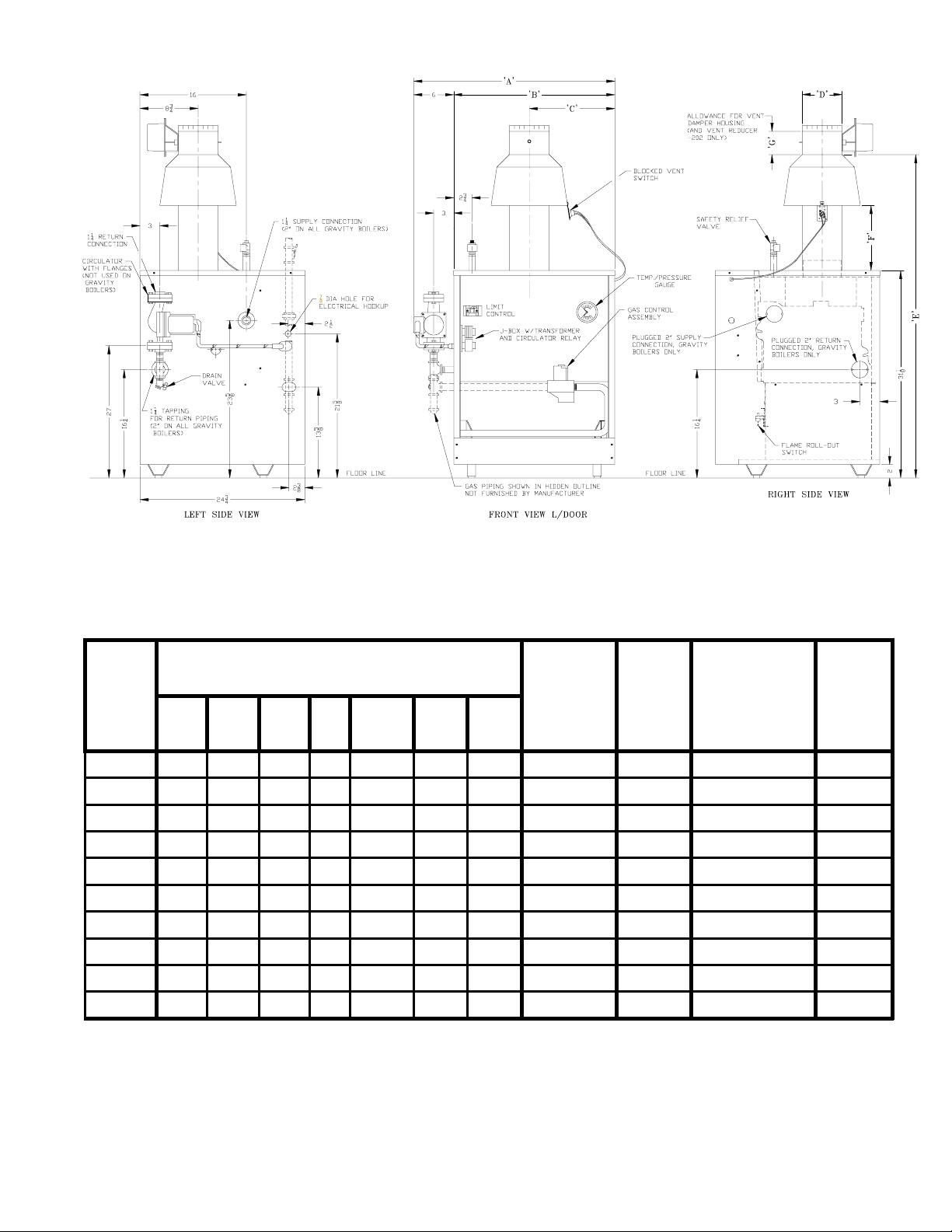
Figure 1
Gas
Boiler
Model
Number
Dimensions [inches]
Connection
ABCDE F G
For
Automatic
Water
Content
[gallons]
Recommended
Vent Size
[1] [2]
Shipping
Gas Va lv e
202 18-3/4 10-3/4 6-3/8 4 45-5/8 8-1/2 10 [3] 1/2 2.5 3" dia. x 15 ft. 212
202X 20 12 6 4 45-5/8 8-1/2 4-3/4 1/2 3.2 4" dia. x 15 ft. 262
203 20 12 6 4 45-5/8 8-1/2 4-3/4 1/2 3.2 4" dia. x 15 ft. 262
204 23-1/4 15-1/4 7-5 /8 5 47-1 /8 9-1/8 4-3/4 1/2 4 5" dia. x 15 ft. 306
205 26-1/2 18-1/2 9-1 /4 6 48-1/2 9-3/4 5-1/4 1/2 4.7 6 " d ia. x 15 ft . 354
206 29-3/4 21-3/4 10-7/8 6 48-1/2 9-3/4 5-1/4 1/2 5.5 6" dia. x 15 ft. 414
207 33 25 12-1/2 7 50-1/8 10-3/8 6-5/8 3/4 6.2 7" dia. x 15 ft. 458
208 36-1/4 28-1/4 14-1/8 7 50-1/8 10-3/8 6-5/8 3/4 7 7" dia. x 15 ft. 514
209 39-1/2 31-1/2 15-3/4 8 52 11 7-1/4 3/4 7.7 8" dia. x 15 ft. 550
210 42-3/4 34-3/4 17-3/8 8 52 11 7-1/4 3/4 8.5 8" dia. x 15 ft. 608
[1] 15' chimney height is from bottom of draft hood opening to top of chimney.
[2] Refer to the National Fuel Gas Code, Apendix G for equivalent areas of circular and rectangular flue linings.
Maximum Allowable Working Pressure - 30 PSI (Water Only)
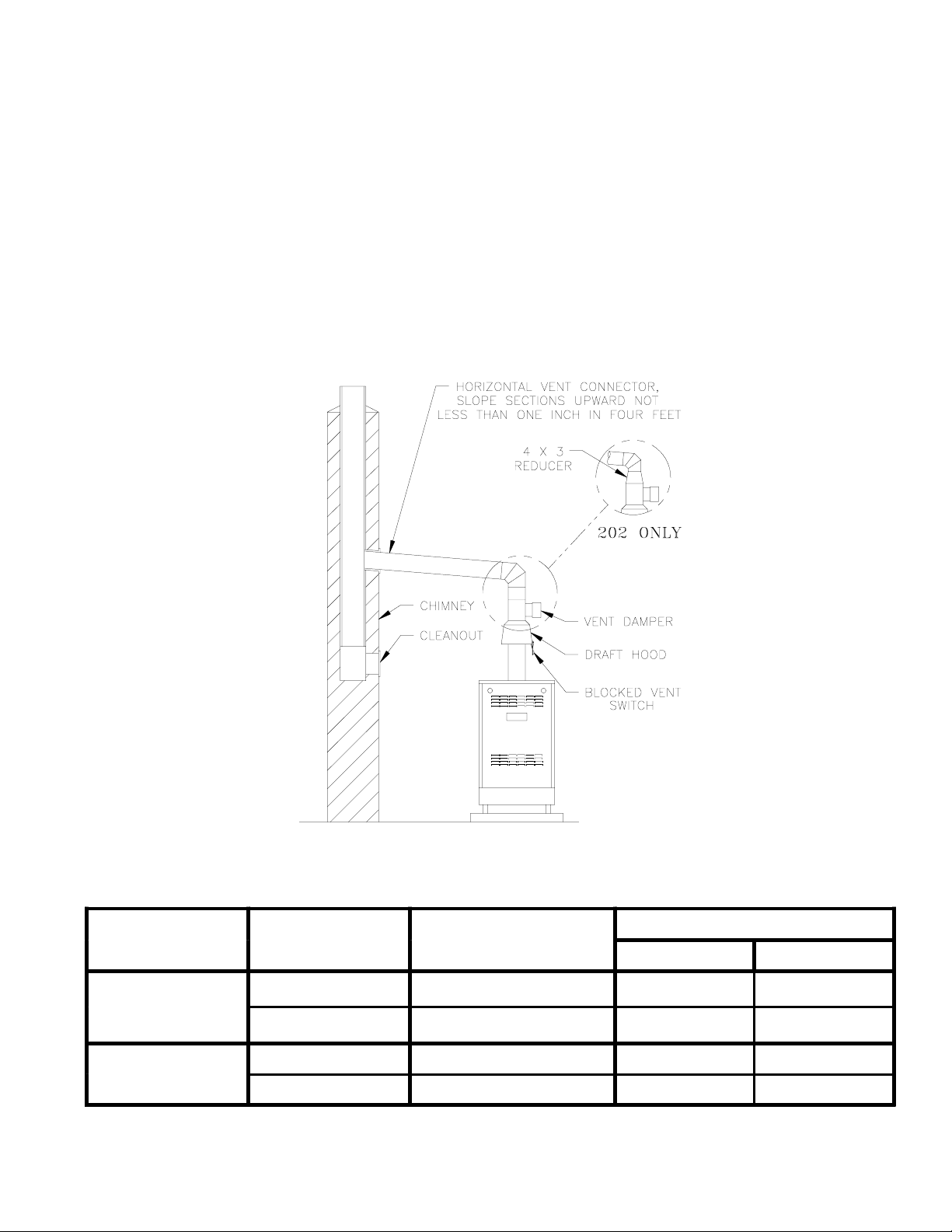
[3] 202 only. Dimension 'G' includes allowance for 4" x 3" reducer furnished with boiler. See Figure 8.
Approx.
Weight
(lb.)
3
Page 4
SECTION I - INSTALLATION INSTRUCTIONS
1. INSPECT SHIPMENT carefully for any signs of damage.
All equipment is carefully manufactured, inspected and
packed. Our responsibility ceases upon delivery of Boiler to
the carrier in good condition. Any claims for damage or
shortage in shipment must be filed immediately against the
carrier by the consignee. No claims for variances or short-
ages will be allowed by Boiler Manufacturer unless pre-
sented within sixty (60) days after receipt of equipment.
2. BOILER INSTALLATION must conform to the require-
ments of the authority having jurisdiction, or in the absence
of such requirements, to:
U.S.A. - National Fuel Gas Code, ANSI Z223.1,
obtainable from the American Gas Association,
1515 Wilson Blvd., Arlington (Rosslyn), VA
22209.
When required by the authority having juris-
diction, the installation must conform to
ANSI/ASME No. CSD-1.
CANADA - "Installation Codes for Natural and LP Gas
Burning Appliances and Equipment, CAN/
CGA-B149.1 or .2-latest edition obtainable
from the Canadian Gas Association, 55 Scars-
dale Road, Don Mills, Ontario, Canada M3B
2R3.
3. These Gas Boilers are DESIGN CERTIFIED FOR
INSTALLATION ON COMBUSTIBLE FLOORING. DO NOT
INSTALL THESE BOILERS ON CARPETING.
F. Slide the boiler forward or backward off the skid using
the two wooden slats as runners.
6. Move boiler to permanent position.
7. PROVIDE CLEARANCE and AIR for COMBUS-
TION and VENTILATION.
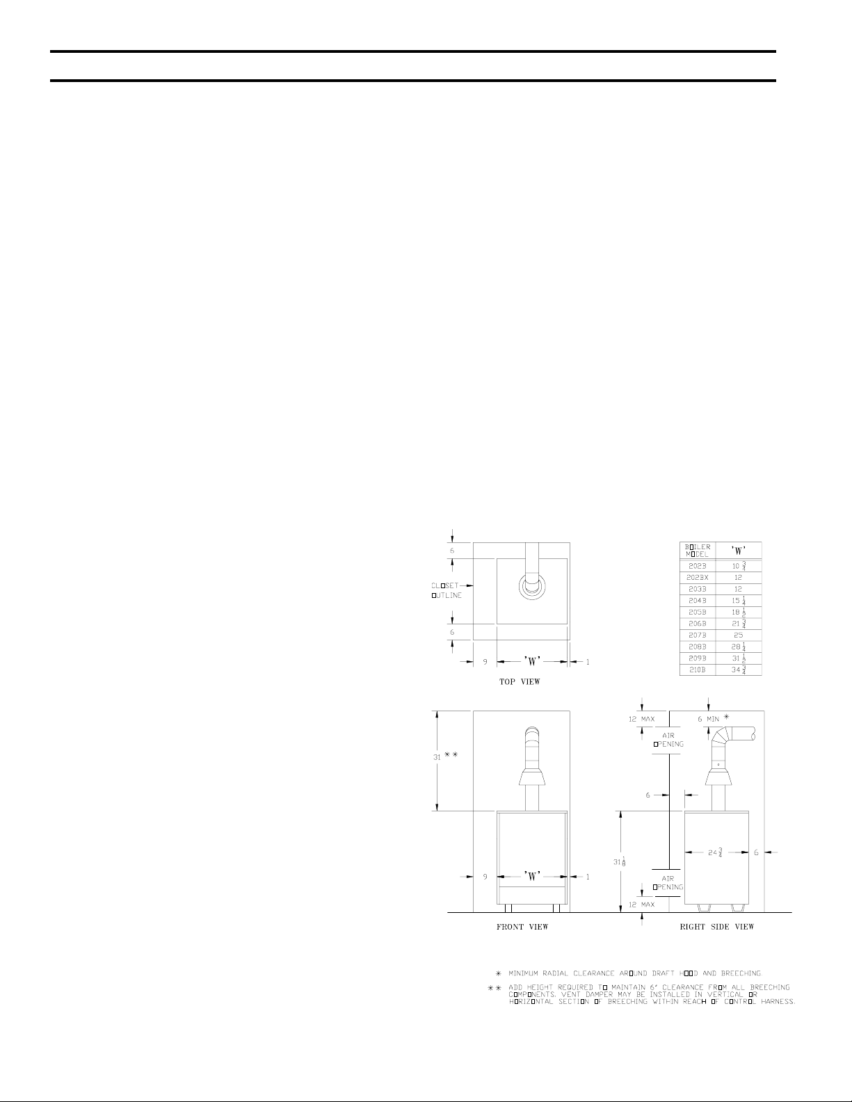
A. CLEARANCES
1. ALL INSTALLATIONS - Practical service clearances
must be considered (see Figure 1). A minimum of
24" from the left side and front jacket panels is
recommended for servicing but may be reduced to
minimum shown in Figure 2. Subject to boiler and
system piping, left side clearance may be reduced to
1" if right side clearance is increased to 9".
2. ALCOVE INSTALLATIONS - An alcove is consid-
ered a closet as shown in Figure 2 less front. Height
clearance may be reduced to 27".
3. UNCONFINED SPACE (see definition, Paragraph (B)
below) - Height clearance may be reduced to 27".
4. LOCATE BOILER in front of or behind installation
position before removing Crate. Locate on a level floor as
close to chimney as possible. For basement installations,
provide a solid base such as concrete, if floor is not level or
if water may be encountered on floor around Boiler.
The boiler shall be installed such that the gas ignition
system components are protected from water (dripping,
spraying, rain, etc.) during boiler operation and service
(circulator replacement, control replacement, etc.).
5. REMOVE CRATE-
A. Remove all crate fasteners. Lift off outside container.
B. Remove all screws and brackets securing boiler to
skid.
C. Save two of the wooden slats from the container sleeve
for use in Steps D & E.
D. Tilt the boiler to one side and slide a wooden slat
under the two raised feet.
E. Tilt the boiler to the other side and slide another
wooden slat under the two raised feet.
Figure 2: Minimum Clearances
4
Page 5

B. PROVIDE COMBUSTION AND VENTILATION AIR in
accordance with applicable provisions of local building
codes, or: U.S.A. - National Fuel Gas Code, NFPA 54/
ANSI Z223.1, Section 5.3, Air for Combustion and
Ventilation; Canada - Natural Gas Installation Code,
CAN/CGA-B149.1, or Propane Installation Code,
CAN/CGA-B149.2, Part 5, Venting Systems and Air
Supply for Appliances.
1. CLOSET INSTALLATIONS (confined space) in a
building of other than unusually tight construction
(see definition below), provide combustion and
ventilation air as shown in Figure 2.
2. Installations other than Paragraph (1) above:
a. Determine volume of space (boiler room). Rooms
communicating directly with space (through
openings not furnished with doors) are considered
part of space.
Volume [ft³] = Length [ft] x Width [ft] x Height [ft]
b. Determine Total Input of all appliances in space.
Round result to nearest 1,000 Btu per hour (Btuh).
c. Determine type of space. Divide Volume by Total
Input.
i. If result is greater than or equal to 50 ft³ per 1,000
Btuh, space is considered an unconfined space.
ii.If result is less than 50 ft³ per 1,000 Btuh, space is
considered a confined space.
d. Determine building type. A building of unusually
tight construction has the following characteristics:
i. Walls and ceiling exposed to outside atmosphere
have a continuous water vapor retarder with a
rating of 1 perm or less with openings gasketed
and sealed, and
ii. Weather-stripping has been added on openable
windows and doors, and
iii.Caulking or sealants applied in joints around
window and door frames, between sole plates and
floors, between wall-ceiling joints, between wall
panels, at plumbing and electrical penetrations,
and at other openings.
e. For boiler located in a building of other than
unusually tight construction, adequate combustion
and ventilation air is normally provided by fresh air
infiltration through cracks around windows and
doors.
f. For boiler located in building of unusually tight
construction, provide outdoor air through two
permanent openings which communicate directly or
by duct with the outdoors or spaces (crawl or attic)
freely communicating with the outdoors. Locate one
opening within 12 inches of top of space. Locate
remaining opening within 12 inches of bottom of
space. Minimum dimension of air opening is 3
inches. Size each opening per following:
i. Direct communication with outdoors. Minimum free
area of 1 square inch per 4,000 Btu per hour input of
all equipment in space.
ii. Vertical ducts. Minimum free area of 1 square inch
per 4,000 Btu per hour input of all equipment in
space. Duct cross-sectional area shall be same as
opening free area.
iii.Horizontal ducts. Minimum free area of 1 square
inch per 2,000 Btu per hour input of all equipment in
space. Duct cross-sectional area shall be same as
opening free area.
g. Ventilation Duct Louvers and Grilles. Equip
outside openings with louvers to prevent entrance
of rain and snow, and screens to prevent entrance of
insects and rodents. Louvers and grilles must be
fixed in open position or interlocked with
equipment to open automatically before burner
operation. Screens must not be smaller than ¼ inch
mesh.
Consider the blocking effect of louvers, grilles and
screens when calculating the opening size to
provide the required free area. If free area of louver
or grille is not known, assume wood louvers have
20-25 percent free area and metal louvers and
grilles have 60-75 percent free area.
8. CONNECT GAS SERVICE from Meter to gas control
assembly in accordance with Local Piping Codes and
requirements of Gas Company, see Figure 1. They may
require piping of larger size than Control Assembly
Connection, especially if run from meter is long or includes
several elbows. (See Figure 1 for size of Gas Connection to
gas control assembly).
This piping is to be supplied by the installer and must
include a trap, a ground joint union and a manual shutoff
valve upstream of the gas control assembly outside of the
jacket when codes require, see Figure 1. A pipe thread
compound resistant to the action of liquefied petroleum
gases should be applied to all threaded joints in the gas
piping. Pressure testing of the Gas Supply Piping Boiler
and its connections is required before placing the boiler in
operation.
The boiler and shutoff valve must be disconnected
from the gas supply piping system during any pressure
testing at pressures greater than ½ psig.
The boiler must be isolated from the gas supply piping
system by closing its individual manual shutoff valve
during any pressure testing of the gas supply piping system
at pressures equal to or less than ½ psig.
RECOMMENDED SIZING OF GAS SUPPLY
PIPING TO BOILER FOR NATURAL GAS - shall be such
as to provide the required supply of gas without undue loss
of pressure between meter and the boiler. Gas supply piping
should be sized in accordance with the Tables 1, 2 and 3.
The following shall be taken into account:
A. Allowable loss of pressure to assure a burner manifold
pressure of 3½" water.
B. Supply of gas to be provided in cubic feet.
C. Length of piping and number of fittings.
D. Specific gravity of gas.
E. Correction factor for specific gravity.
5
Page 6
9. BOILER PIPING
CAUTION
Failure to properly pipe boiler may result in
improper operation and damage to boiler or
building.
A. CLEARANCES - Hot water pipes do not require
clearance from combustible construction.
B. Install drain cock and safety relief valve as shown in
Figure 4. Note - Safety relief valve must be in vertical
position.
C. Pipe safety relief valve discharge to floor.
WARNING
Safety relief valve discharge piping mus t
be piped near floor t o eliminate potential
of severe burns. Do not pipe in any area
where freezing could occur. Do not i nstall
any shut-off valves .
D. Install circulator with flanges, gaskets and bolts
provided. Five foot long circulator harness allows
circulator to be mounted on supply or return. Connect
harness to circulator and secure any excess conduit.
E. For heating only system piping, see Figure 3. Consult
also I=B=R Installation Guides.
F. Space heating and domestic water heating with Alliance
water heater (intermittent circulation only). Install
Alliance water heater as a separate heating zone. Refer
to Alliance Installation, Operating and Service Instruc-
tions for additional information.
G. If this boiler is used in connection with refrigeration
systems, the boiler must be installed so that the chilled
medium is piped in parallel with the heating boiler using
appropriate valves to prevent the chilled medium from
entering the boiler, see Figure 4. Also consult I=B=R
Installation and Piping Guides.
If this Boiler is connected to heating coils located in
air handling units where they may be exposed to
refrigerated air, the boiler piping must be equipped
with flow control valves to prevent gravity circulation
of boiler water during the operation of the cooling
system.
H. Use a boiler bypass if the boiler is to be operated in a
system which has a large volume or excessive radia-
tion where low boiler water temperatures may be
encountered (i.e. converted gravity circulation system,
etc.).
Remove the circulator and install a pipe tee between the
circulator and boiler return along with a second tee in
the supply piping as shown in Figure 5. The bypass
should be the same size as the supply and return lines
with valves located in the bypass and supply outlet as
illustrated in Figure 5 in order to regulate water flow
to maintain higher boiler water temperatures.
Set the by-pass and boiler supply valves to a half
throttle position to start. Operate boiler until the
system water temperature is at a normal operating
range.
Adjust the valves to provide 180° to 200°F supply
water temperature. Opening the boiler supply valve
will raise the system temperature, while opening the
by-pass valve will lower the system supply tempera-
ture.
I. A hot water boiler installed above radiation level must
be provided with a low water cutoff device as part of
the installation.
J. OXYGEN CORROSION:
Oxygen contamination of the boiler water will cause
corrosion of the iron and steel boiler components,
which can lead to failure. As such, any system must be
designed to prevent oxygen absorption in the first
place or prevent it from reaching the boiler. Problems
caused by oxygen contamination of boiler water are not
Length
[Feet]
10 132 278 520 1,050 175 360 680 1,400
20 92 190 350 730 120 250 465 950
30 73 152 285 590 97 200 375 770
40 63 130 245 500 82 170 320 660
50 56 115 215 440 73 151 285 580
60 50 105 195 400 66 138 260 530
70 46 96 180 370 61 125 240 490
80 43 90 170 350 57 118 220 460
90 40 84 160 320 53 110 205 430
100 38 79 150 305 50 103 195 400
0.3 inch w.c. Pressure Drop 0.5 inch w.c. Pressure Drop
½¾ 11¼½¾ 11¼
6
Page 7
Table 2: Equivalent Length of Fittings Table 3: Specific Gravity Correction Factors
Fitting
Nominal Pipe Size
½¾ 11¼
45° Ell 0.7 1 1.2 1.6
90° Ell 1.6 2.1 2.6 3.5
Tee (As Elbo w) 3.1 4.1 5.2 6.9
covered by Burnham's standard warranty.
There are many possible causes of oxygen contamina-
tion such as:
1. Addition of excessive make-up water as a result of
system leaks.
2. Absorption through open tanks and fittings.
3. Oxygen permeable materials in the distribution system.
In order to insure long product life, oxygen sources
should be eliminated. This can be accomplished by
taking the following measures:
1. Repairing system leaks to eliminate the need for
addition of make-up water.
2. Eliminating open tanks from the system.
3. Eliminating and/or repairing fittings which allow
oxygen absorption.
4. Use of non-permeable materials in the distribution
system.
5. Isolating the boiler from the system water by installing
a heat exchanger.
10. INSTALL DRAFT HOOD without modification on outlet
of flue collector (See Figure 1). Secure with sheet metal
screws.
Specific
Gravity
0.50 1.10 1.30 1.07
0.55 1.04 1.40 1.04
0.60 1.00 1.50 1.00
0.65 0.96 1.6 0.97
0.70.931.70.94
0.75 0.9
0.8 0.87
C. Position the mounting bracket (with switch attached)
onto the lower edge of the draft hood skirt by locating
the center tooth (with the #10 sheet metal screw) on the
outside and the other two teeth inside the draft hood
skirt. See Fig. 6.
D. Slide the mounting bracket up tight against the lower
edge of the draft hood skirt, so that the #10 sheet metal
screw is above the skirt's stiffening rib.
E. Secure the bracket in this position by tightening the
#10 sheet metal screw against the outer surface of the
draft hood skirt.
F. Reinsert the excess power cord through the jacket side
panel hole to take the slack out of the power cord
running up to the blocked vent switch.
G. Reposition the strain relief bushing around the power
cord at the jacket side panel, pinch the two halves of
the bushing together, and snap it back into the hole in
Correction
Factor
Specific
Gravity
Correction
Factor
11. INSTALL BLOCKED VENT SWITCH
The blocked vent switch assembly shipped taped to the top
of the boiler includes a power cord and a switch attached to
a mounting bracket. The mounting bracket has a three
tooth staggered comb stamping at one end with a #10 sheet
metal screw in the center tooth.
A. Untape the blocked vent switch assembly from the top
of the boiler and uncoil the power cord.
B. Pinch the black strain relief bushing installed in the
jacket right side panel to dislodge it from the jacket
and pull just enough of the black power cord out so the
blocked vent switch will reach the near side of the draft
hood skirt. Do not pull out more power cord than
necessary.
7
Figure 3: Boiler Piping
Page 8
Figure 4: Recommended Piping for Combination
Heating & Cooling (Refrigeration) Systems
the jacket side panel to secure the power cord to the
jacket.
H. Be sure the power cord, mounting bracket, and switch
are secure and located as shown in Figure 6.
WARNING
Failure to properly install and use this
Blocked Vent Switch may result in property
damage, personal injury or loss of life.
12. TO MEET FEDERALLY MANDATED EFFICIENCIES,
THIS BOILER MUST BE EQUIPPED WITH A VENT
DAMPER.
OPEN THE VENT DAMPER CARTON and remove the
Installation Instructions. READ THE INSTALLATION
INSTRUCTIONS THOROUGHLY before proceeding.
The automatic gas control valve supplied on each
Series 2 boiler provides the reduncancy referenced in the
vent damper Installation Instructions.
Figure 6
A. The vent damper should be the same size as the outlet
of the Draft Hood. (See Figure 1) Unpack the damper
carefully - DO NOT FORCE IT CLOSED! Forcing the
damper may damage the gear train and void the
warranty. The damper assembly includes a prewired
connection harness for use on all 24V Standing Pilot or
intermittent ignition control systems.
B. Refer to Figure 7 in this manual.
C. Mount the vent damper assembly on the draft hood
without modification to either. (Refer to instructions
packed with the vent damper for specific instructions).
This is a must for the wiring harness to fit and the
damper position indicator to be visible to the users.
Figure 5
NOTICE
Please refer to the specifications,
installation instructions and troubleshooting
guide packed in the vent damper carton for
complete detailed installation instructions.
Also refer to Figure 7 in this manual.
D. Install the 90° BX connector attached to the flexible
conduit in the 7/8" knockout on the left side of the
jacket. Plug the factory wired Vent Damper Harness
into the polarized receptacle. Install a cable clamp
around the flexible conduit and attach to the Jacket top
panel. (See Figure 7).
8
Page 9

E. Continuous Ignition (Standing Pilot) Only. Remove
knockout from vent damper blade.
F. Size 202 Only. Install 4" x 3" reducing fitting on vent
damper outlet (or draft hood outlet for Canadian boiler
not equipped with vent damper).
13. INSTALL VENT CONNECTOR from reducing fitting
(202 Only), draft hood or damper to chimney, see Fig. 8.
A. Vent installation shall be in accordance with local
building codes; or the local authority having jurisdic-
tion; or the National Fuel Gas Code, ANSI Z223.1/
NFPA 54; or the Standard for Chimneys, Fireplaces,
Vents, and Solid Fuel Burning Appliances, ANSI/NFPA
211. Both of the aforementioned standards, ANSI
Z223.1 and ANSI/NFPA 211, specify Type B and Type
L double wall metal vents and fire clay tile lined
masonry chimneys as suitable chimney constructions
for Category I, draft hood equipped appliances, such as
this Series 2 boiler. Both standards prohibit the use of
unlined masonry construction as a chimney, with the
exception in ANSI Z223.1/NFPA 54 that "Where
permitted by the authority having jurisdiction, existing
chimneys shall be permitted to have their use continued
when an appliance is replaced by an appliance of similar
type, input rating, and efficiency." ANSI/NFPA 211
prohibits the use of single wall metal vent as a chimney,
while ANSI Z223.1 allows it under very restrictive
conditions. In Canada refer to the Natural Gas Installa-
tion Code, CAN/CGA-B149.1 or the LP Gas Installation
Code, CAN/CGA-B149.2 - latest edition.
B. Do not connect into same leg of chimney serving an
open fireplace.
C. Inspect chimney for obstructions or restrictions and
remove. Clean chimney if necessary.
D. Vent pipe to chimney must not be smaller than outlet
on draft hood or damper. Although single wall vent
pipe may be used, Type B is recommended. The
venting system must be arranged so that only the
boiler is served by the damper device. Installation per
paragraph 12 complies with this provision.
E. Where two or more appliances vent into a common
vent, the area of the common vent should at least
equal the area of the largest vent plus 50% of the area
in the additional vents. Do not connect the vent of this
appliance into any portion of mechanical draft system
operating under positive pressure.
F. Vent pipe should have the greatest possible initial rise
above the draft hood consistent with the head room
available and the required clearance from adjacent
combustible building structure. Vent Pipe should be
installed above the bottom of chimney to prevent
blockage.
G. Vent pipe should slope upward from draft hood to
chimney not less than one inch in four feet. No portion
of vent pipe should run downward or have dips or
sags. Vent pipe must be securely supported.
H. Vent pipe must be inserted into but not beyond inside
wall of chimney liner. Seal tight between vent pipe
and chimney.
I. Do not install non-listed (AGA, CGA, ETL or UL) vent
damper or other obstruction in vent pipe.
14. IF AN EXISTING BOILER IS REMOVED -
When an existing boiler is removed from a common
venting system, the common venting system is likely to be too
large for proper venting of the appliances remaining to it.
At the time of removal of an existing boiler, the follow-
ing steps shall be followed with each appliance remaining
connected to the common venting system placed in operation,
while the other appliances remaining connected to the
common venting system are not in operation:
A. Seal any unused openings in the common venting
system.
B. Visually inspect the venting system for proper size and
horizontal pitch and determine there is no blockage or
restriction, leakage, corrosion, and other deficiencies
which could cause an unsafe condition.
C. Insofar as is practical, close all building doors and
windows and all doors between the space in which the
appliances remaining connected to the common venting
system are located and other spaces of the building.
Turn on clothes dryers and any appliance not connected
to the common venting system. Turn on any exhaust
fans, such as range-hoods and bathroom exhausts, so
they will operate at maximum speed. Do not operate a
summer exhaust fan. Close fireplace dampers.
D. Place in operation the appliance being inspected. Follow
the Lighting (or Operating) Instructions. Adjust
thermostat so appliance will operate continuously.
E. Test for spillage at the draft hood relief opening after 5
minutes of main burner operation. Use the flame of a
match or candle, or smoke from a cigarette, cigar or
pipe.
F. After it has been determined that each appliance remain-
ing connected to the common venting system properly
vents when tested as outlined above, return doors,
windows, exhaust fans, fireplace dampers and any other
gas burning appliance to their previous conditions of use.
G. Any improper operation of the common venting system
should be corrected so the installation conforms with the
National Fuel Gas Code, NFPA 54/ANSI Z223.1. When
resizing any portion of the common venting system, the
common venting system should be resized to approach
the minimum size as determined using the appropriate
tables in Part 11 in the National Fuel Gas Code, NFPA
9
Page 10
Figure 7: Plug-in Damper Installation
10
Page 11
54/ANSI Z223.1.
15. INSTALL A ROOM THERMOSTAT on an inside wall
about four feet above floor. Never install thermostat on an
outside wall or where it will be influenced by drafts, hot or cold
water pipes, lighting fixtures, television, rays of the sun or near
a fireplace. Keep large furniture away from thermostat so there
will be free movement of room air around this control.
Heat Anticipator in Thermostat should be set to match the
requirements of the control to which it is connected. See Table
4. If system tends to overheat above the thermostat's
temperature setting, reduce heat anticipator setting by .1 or.2
amps. If system tends to short cycle without reaching desired
room temperature, increase heat anticipator setting by .1 or .2
amps.
16. INSTALL ELECTRIC WIRING in accordance with
National Electric Code or the Canadian Electrical Code and
local regulations. See Figures 11 through 14 for applicable
wiring diagram. A separate Electrical Circuit should be run
from meter with a Fused Disconnect Switch in this Circuit.
When installed, the boiler must be electrically grounded in
accordance with local codes or, in the absence of local
codes, with the National Electrical Code, ANSI/NFPA 70,
and/or the CSA C22.1 Electrical Code, if an external electrical
source is utilized.
For zone valve wiring, a separate 24V transformer is
required rather than attempting to use the boiler mounted
control. Consult zone valve manufacturer for assistance.
17. VENT DAMPER SEQUENCE OF OPERATION
Effikal and Johnson Damper
Figure 8: Typical Vent Installation
Table 4: Wiring Diagrams and Heat Anticipator Settings
Ignition Type Circulation Method
Continuous
(Standing Pilot)
Intermittent
If system tends to overheat above thermostat's temperature setting, reduce heat anticipator setting by 0.1
or 0.2 amps. If system tends to shortcycle without reaching desired room temperature, increase heat
anticipator setting by 0.1 or 0.2 amps.
Intermittent 0.6 11 13
Constant/Gravity 1.0 14 18
Intermittent 0.6 12 14
Constant/Gravity 1.0 13 16
Thermostat Heat
Anticipator Setting [ Amps]
11
Figure Number Page Number
Wiring Diagram
Page 12
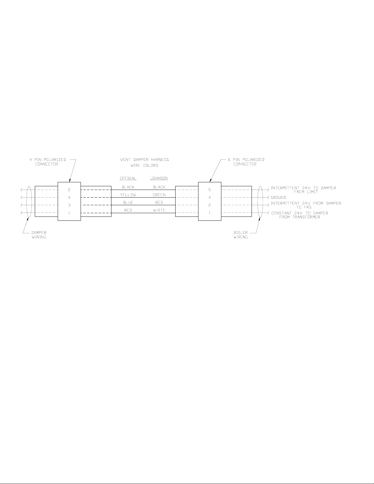
A. The Vent Damper is continuously powered at Terminal
1.
B. When there is a call for heat, the damper relay coil is
energized through Terminal 5 if all limits ahead of the
damper are satisfied.
C. The relay coil closes contacts which energize the
damper motor, causing the damper to open.
D. When the damper blade reaches the fully open posi-
tion, power is sent back to the ignition circuit through
Terminal 2 and the damper motor is de-energized.
E. When the call for heat is satisfied, the damper relay coil
is deenergized - closing contacts which energize the
damper motor. This causes the damper to close. When
the damper blade reaches the fully closed position, the
damper motor is de-energized.
POWER FAILURE - The damper blade will stop in the
position it was in when power failed. (Combustion can
never take place unless the damper blade is in the fully
open position.)
Figure 9: Vent Damper Schematic Wiring Diagram
12
Page 13
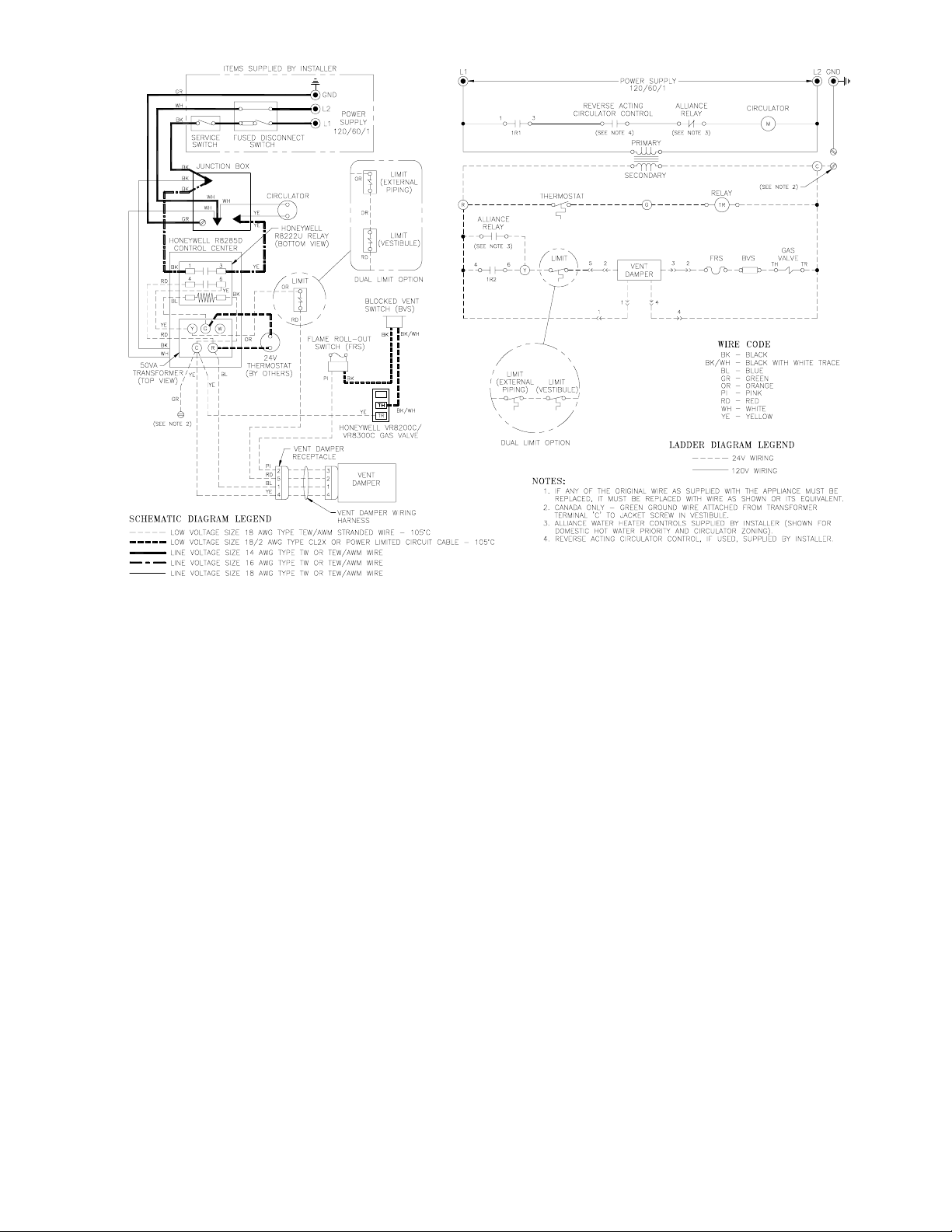
Figure 11: Wiring Diagram, 24 Volt Standing Pilot and Intermittent Circulation
SEQUENCE OF OPERATION
NORMAL OPERATION
1. When the thermostat call for heat, the vent damper
will open (see paragraphs 17A through 17D). The
circulator is started through a relay and at the same
time the gas valve is energized allowing main gas flow
and ignition of main burners.
2. Where condensation of flue gas is encountered in
boiler flues a reverse acting circulator control should
be installed to stop the circulator before the boiler
water temperature drops to that which flue gas
condensation may occur.
3. After the thermostat is satisfied the main valve will
close and main burner flames will be extinguished.
The vent damper will close (see paragraph 17E).
SAFETY SHUTDOWN
1. High Limit Switch
In the event excessive boiler water temperature is
developed the high limit switch will open interrupting
power to the gas valve. The main burners will be
extinguished immediately, and the vent damper will
close at the same time, but the circulator will continue
to operated. Normal operation will be resumed when
the boiler water temperature drops to a point where
the high limit switch closes.
2. Blocked Vent Switch
In the event excessive blockage in the vent system is
developed the blocked vent switch will open interrupt-
ing power to the gas valve. The main burners will be
extinguished immediately, the circulator will continue
to operate, and the vent damper will remain open until
the thermostat is turned off. The source of blockage
must be corrected by trained and skilled personnel
from a qualified service agency before resetting
switch.
3. Flame Rollout Switch
In the event excessive blockage in the boiler section
flue passageways is developed the flame rollout switch
will open interrupting power to the gas valve. The
main burners will be extinguished immediately, the
circulator will continue to operate and the vent
damper will remain open until the thermostat is
turned off. If the flame rollout switch is activated do
not attempt to place the boiler in operation. The source
of blockage must be corrected and the flame rollout
switch replaced by trained and skilled personnel from
a qualified service agency.
4. Pilot
The thermocouple proves pilot flame and in the
absence of such within 45-90 seconds causes the
combination gas valve, which is equipped with a
100% shut-off provision, to be de-energized, thus,
preventing main gas or pilot gas flow.
13
Page 14
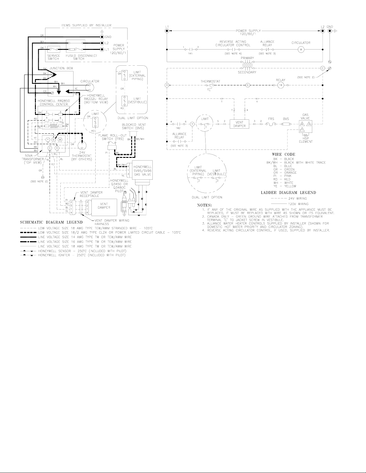
Figure 12: Wiring Diagram, Intermittent Ignition and Intermittent Circulation
14
Page 15

SEQUENCE OF OPERATION
NORMAL OPERATION
1. When the THERMOSTAT calls for heat, the RELAY
is energized. The CIRCULATOR starts and the
VENT DAMPER is opened (see Paragraphs 17A
through 17D). When the damper blade reaches the
fully open position, the GAS VALVE powers the
igniter circuit and opens the pilot valve.
2. The sensing circuit between the Q3450 or Q3480 pilot
and the GAS VALVE proves presence of pilot flame.*
3. The GAS VALVE de-energizes the igniter and opens
the main valve, allowing main gas to flow and
ignition of main burners.
4. Where condensation of flue gas is encountered in
boiler flues, a REVERSE ACTING CIRCULATOR
CONTROL should be installed to stop the CIRCULA-
TOR before the boiler water temperature drops to that
at which flue gas condensation may occur.
5. The burners and CIRCULATOR will operate simulta-
neously until the THERMOSTAT is satisfied.
6. After the THERMOSTAT is satisfied the main valve,
pilot valve and the circulator will be de-energized and
main burner and pilot flames will be extinguished.
The VENT DAMPER will close (see Paragraph 17E).
SAFETY SHUTDOWN
1. High Limit Switch
In the event excessive boiler water temperature is
developed the High Limit Switch will open, interrupt-
ing power to the VENT DAMPER and the GAS
VALVE. Main Burners and Pilot Burner will be
extinguished immediately. Normal operation will be
resumed when the boiler water temperature drops to a
point where the High Limit Switch closes.
2. Blocked Vent Switch
In the event excessive blockage in the vent system is
developed the blocked vent switch will open interrupt-
ing power to the VENT DAMPER and GAS VALVE.
Main burners and pilot burner will be extinguished
immediately, the VENT DAMPER will close and the
CIRCULATOR will continue to operate. The source
of blockage must be corrected by trained and skilled
personnel from a qualified service agency before
resetting switch.
3. Flame Rollout Switch
In the event excessive blockage in the boiler section
flue passageways is developed the flame rollout switch
will open interrupting power to the VENT DAMPER
and the GAS VALVE. Main burners and pilot burner
will be extinguished immediately. The VENT
DAMPER will close and the CIRCULATOR will
continue to operate. If the flame rollout switch is
activated do not attempt to place the boiler in opera-
tion. The source of blockage must be corrected and the
flame rollout switch replaced by trained and skilled
personnel from a qualified service agency.
4. Pilot
A. Any pilot failure on the Q3450 or Q3480 Pilot will
close the main gas valve and energize the igniter.
B. If the igniter breaks or becomes disconnected, the pilot
valve coil loses power, closing the pilot valve.
5. For TROUBLE SHOOTING GUIDE, see Figure 28.
* · SV9500 and SV9600 Gas Valves:
The igniter and pilot gas valve will stay energized
until either the pilot lights or the call for heat ends.
· SV9501 and SV9601 Gas Valves:
If the pilot fails to light after a 90 second trial for
ignition, the igniter will be de-energized and the pilot
gas valve will close. After a 5 minute delay, the
igniter will be re-energized and the pilot gas valve will
re-open. This continuous retry cycle will end either
when the pilot lights or the call for heat ends.
15
Page 16
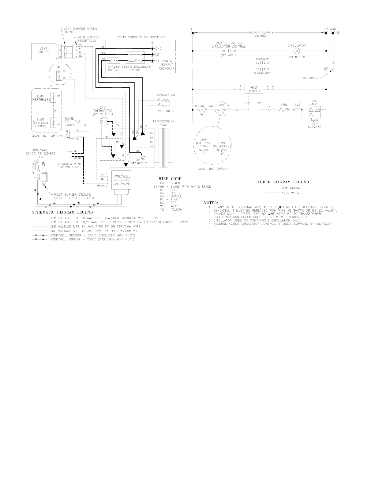
Figure 13: Wiring Diagram, Intermittent Ignition and Continuous or Gravity Circulation
16
Page 17

SEQUENCE OF OPERATION
NORMAL OPERATION
1. When THERMOSTAT calls for heat, the VENT
DAMPER is opened (see Paragraphs 17A through
17D). When the damper blade reaches the fully open
position, the GAS VALVE powers the igniter circuit
and opens the pilot valve.
2. The sensing circuit between the Q3450 or Q3480 pilot
and the GAS VALVE proves presence of pilot flame.*
3. The GAS VALVE de-energizes the igniter and opens
the main valve, allowing main gas to flow and
ignition of main burners.
4. On Boilers equipped with Circulators that are wired to
run continuously and, where condensation of flue gas
is encountered in boiler flues, a REVERSE ACTING
CIRCULATOR CONTROL should be installed to stop
the Circulator before the Boiler Water Temperature
drops to that at which flue gas condensation may
occur.
5. The Burners will operate until the THERMOSTAT is
satisfied.
6. After the THERMOSTAT is satisfied the GAS
VALVE will be de-energized. The Main Burners and
Pilot Burner will be extinguished. If Boiler is
equipped with circulator, Circulator will continue to
run. The VENT DAMPER will close (see Paragraph
17E).
SAFETY SHUTDOWN
1. High Limit Switch
In the event excessive boiler water temperature is
developed, the High Limit will open, interrupting
power to the IGNITION MODULE and the DUAL
COMBINATION GAS VALVE. Main Burners and
Pilot Burner will be extinguished immediately and the
vent damper will close. Normal operation will be
resumed when the Boiler Water Temperature drops to
a point where the High Limit Switch closes.
2. Blocked Vent Switch
In the event excessive blockage in the vent system is
developed the blocked vent switch will open interrupt-
ing power to the ignition module and dual combina-
tion gas valve. Main burners and pilot burner will be
extinguished immediately and the vent damper will
close. The source of blockage must be corrected by
trained and skilled personnel from a qualified service
agency before resetting switch.
3. Flame Rollout Switch
In the event excessive blockage in the boiler section
flue passageways is developed the flame rollout switch
will open interrupting power to the ignition module
and the dual combination gas valve. Main burners and
pilot burner will be extinguished immediately and the
vent damper will close. If the flame rollout switch is
activated do not attempt to place the boiler in opera-
tion. The source of blockage must be corrected and the
flame rollout switch replaced by trained and skilled
personnel from a qualified service agency.
4. Pilot
A. Any pilot failure on the Q3450 or Q3480 pilot will
close the main gas valve and energize the igniter.
B. If the igniter breaks or becomes disconnected, the pilot
valve coil loses power, closing the pilot valve.
5. For TROUBLE SHOOTING GUIDE, see Figure 28.
* · SV9500 and SV9600 Gas Valves:
The igniter and pilot gas valve will stay energized
until either the pilot lights or the call for heat ends.
· SV9501 and SV9601 Gas Valves:
If the pilot fails to light after a 90 second trial for
ignition, the igniter will be de-energized and the pilot
gas valve will close. After a 5 minute delay, the
igniter will be re-energized and the pilot gas valve will
re-open. This continuous retry cycle will end either
when the pilot lights or the call for heat ends.
17
Page 18

Figure 14: Wiring Diagram, 24 Volt Standing Pilot with Continuous or Gravity Circulation
SEQUENCE OF OPERATION
NORMAL OPERATION
1. When the thermostat call for heat, the vent damper
will open (see paragraphs 17A through 17D). The gas
valve is energized allowing main gas to flow and
operation of the main burners.
2. Where condensation of flue gas is encountered in
boiler flues a reverse acting circulator control should
be installed to stop the circulator before the boiler
water temperature drops to that which flue gas
condensation may occur.
3. After the thermostat is satisfied the main valve will
close and main burner flames will be extinguished.
The vent damper will close (see paragraph 17E). If the
boiler is so equipped, circulator will continue to run.
SAFETY SHUTDOWN
1. High Limit Switch
In the event excessive boiler water temperature is
developed the high limit switch will open interrupting
power to the gas valve. The main burners will be
extinguished immediately. Normal operation will be
resumed when the boiler water temperature drops to a
point where the high limit switch closes.
2. Blocked Vent Switch
In the event excessive blockage in the vent system is
developed the blocked vent switch will open interrupt-
ing power to the gas valve. The main burners will be
extinguished immediately and the vent damper will
remain open until the thermostat is turned off. The
source of blockage must be corrected by trained and
skilled personnel from a qualified service agency
before resetting switch.
3. Flame Rollout Switch
In the event excessive blockage in the boiler section
flue passageways is developed the flame rollout switch
will open interrupting power to the gas valve. The
main burners will be extinguished immediately and
the vent damper will remain open until the thermostat
is turned off. If the flame rollout switch is activated do
not attempt to place the boiler in operation. The source
of the blockage must be corrected and the flame
rollout switch replaced by trained and skilled person-
nel from a qualified service agency.
4. Pilot
The thermocouple proves pilot flame and in the
absence of such within 45-90 seconds causes the
combination gas valve, which is equipped with a
100% shut-off provision, to be de-energized, thus,
preventing main gas or pilot gas flow.
18
Page 19

Figure 15: Wiring Schematic, Zone Valves
Figure 16: Wiring Schematic, Zone Circulators
19
Page 20

SECTION II - OPERATING INSTRUCTIONS
Safe lighting and other performance criteria were met with the gas manifold and control assembly provided on the boiler when
the boiler underwent tests specified in American National Standard for Gas-Fired Low-Pressure Steam and Hot Water Boilers,
ANSI Z21.13b-1994.
1. MAIN BURNER CHECK - Check main burners to see
that they were not dislodged during shipment. Rear of burners
should be in the slots in the rear of burner tray and the front
of the burners should be seated completely on the orifices.
2. INITIAL START -
A. FILL ENTIRE HEATING SYSTEM WITH WATER
and vent air from system. Use the following procedure
on a Series Loop System equipped with zone valves. (See
Figure 3).
1. Close isolation valve in boiler supply piping.
2. Isolate all circuits by closing zone valves or balancing
valves.
3. Attach a hose to bib cock located just below isolation
valve in boiler supply piping. (Note - Terminate hose in
five gallon bucket at a suitable floor drain or outdoor
area).
4. Starting with one circuit, open zone valve.
5. Open bib cock.
6. Open fill valve (Make-up water line should be located
directly above isolation valve in boiler supply piping).
7. Allow water to overflow from bucket until discharge
from hose is bubble free for 30 seconds.
8. Open zone valve to the second zone to be purged, then
close the first. Repeat this step until all zones have been
purged, but always have one zone open. At completion,
open all zone valves.
9. Close bib cock, continue filling the system until the
pressure gauge reads 12 psi. Close fill valve. (Note - If
make-up water line is equipped with pressure reducing
valve, system will automatically fill to 12 psi. Leave
globe valve open).
10. Open isolation valve in boiler supply piping.
11. Remove hose from bib cock.
B. Turn ROOM THERMOSTAT to lowest setting.
C. Be sure that gas to pilot and main burners has been off
for at least five minutes and vent damper (if used) has
been in the open position.
D. Turn "OFF" the electric switch serving boiler.
E. Open valve on main gas line at meter.
F. PURGE AIR FROM GAS PIPING. This procedure will
vary with equipment furnished but in all cases adequate
ventilation must be provided and no smoking or open
flame permitted. To determine which of the procedures
outlined in succeeding paragraphs is applicable, match
suffix of boiler model found on Rating Plate with
paragraph heading:
1. Standing Pilot Models (Suffix V):
a. Keep electric switch "OFF".
b. Open Manual Shut-off Valve upstream of Combination
Gas Valve.
c. Disconnect Pilot Tubing at gas valve (Purge must not
be into combustion chamber).
d. Turn Main Gas Knob on Combination Gas Valve to
20
Figure 17: Schematic Pilot and Gas Piping
Continuous Ignition (Standing Pilot)
Figure 18: Schematic Pilot and Gas Piping
Intermittent Ignition (HSP)
"Pilot" Position. Depress and hold in this position
until purging is complete. Turn Main Gas Knob to
"off" position.
e. Reconnect pilot tubing and check pipe and fittings
from meter to combination Gas Valve for leaks using
soap solution or other approved method.
2. Intermittent Ignition Models (Suffix S):
a. Turn "ON" electric switch serving boiler.
b. Open Manual Shut-off Valve upstream of
Combination Gas Valve.
Page 21

c. Loosen or remove Inlet Pressure Tap Plug in
Combination Gas Valve and when purging is
complete, tighten or replace plug. (See Figure 19).
d. Check pipe and fittings from meter to Combination
Gas Valve using soap solution or other approved
methods.
e. Test gas piping and connections between
Combination Gas Valve and manifold, orifices,
and pilot piping for leaks after boiler is operating.
Use soap solution or other approved method.
3. INSTRUCTIONS TO PUT THE BOILER IN OPERA-
TION. See Figure 20 for intermittent ignition. See Figure
21 for continuous ignition system (standing pilot).
Figure 19a: Top View of SV9500, SV9600 and
VR Gas Valves
21460147
Figure 20a: Operating Instructions, SV9500 and SV9600 Gas Valves
21
Page 22

Honeywell
Figure 19b: Top View of Honeywell SV9501 and SV9601 Gas Valves
FOR YOUR SAFETY READ BEFORE OPERATING
WARNING
Fire or Explosion Hazard.
Can cause property damage, severe injury
or death.
Force or attempted repair may result in a fire or
explosion.
Follow these instructions exactly.
1. This appliance is equipped with an ignition device
which automatically lights the pilot. DO NOT try to
light the pilot by hand.
2. smell all around the appliance
BEFORE OPERATING
area for gas. Be sure to smell next to the floor
because some gas is heavier than air and settles
on the floor.
WHAT TO DO IF YOU SMELL GAS:
Do not try to light any appliance.
Do not touch any electric switch other than the
gas valve; do not use any phone in your
building.
Immediately call your gas supplier from a
neighbor's phone. Follow the gas supplier's
instructions.
If you cannot reach your gas supplier, call the
fire department.
3. Use only your hand to slide the gas control switch to
"ON". Never use tools. If the switch does not move
by hand, DO NOT try to repair it; call a qualified
service technician. Force or attemped repair may
result in a fire or explosion.
4. Do not use this appliance if any part has been
under water. Immediately call a qualified service
technician to inspect the appliance. Replace any
part of the control system and any gas control
that has been under water.
OPERATING INSTRUCTIONS
1. STOP! Read the safety information above on this
label.
2. Set the thermostat to the lowest setting.
3. Turn off all electric power to the appliance.
4. This appliance is equipped with an ignition device
that automatically lights the pilot. DO NOT try to
light the pilot by hand.
5. Remove front door.
6. Slide gas control switch to "OFF".
7. Wait five (5) minutes to clear out any gas. Then smell
for gas, including near floor. If you smell gas, STOP!
GAS
INLET
IGNITION SYSTEM
CONTROL SWITCH
TO TURN OFF GAS TO APPLIANCE
1. Set the thermostat to the lowest setting.
2. Turn off all electric power to the appliance if
service is to be performed.
3. Remove front door.
Follow step 2 in the section
above on this label. If you do not smell gas, go to
the next step.
8. Slide gas control switch to "ON".
9. Replace front door.
10. Turn on all electric power to the appliance.
11. Set the thermostat to desired setting.
12. If the appliance does not operate, follow the
instructions
and call your service technician or gas supplier.
"FOR YOUR SAFETY"
"TO TURN OFF GAS TO APPLIANCE"
Honeywell
OUTLET
4. Slide gas control switch to "OFF". DO NOT force.
5. Replace front door.
Figure 20b: Operating Instructions, SV9501 and SV9601 Gas Valves
22
Page 23

81460177
Figure 21: Lighting Instructions
23
Page 24

4. CHECK GAS INPUT RATE TO BOILER
USA boilers built for installation at altitudes greater than
2,000 feet above sea level have been specially orificed to
reduce gas input rate 4 percent per 1,000 feet above sea level
per the National Fuel Gas Code, NFPA 54/ANSI Z223.1,
Section 8.1.2 and Appendix F. Canadian boilers' orifice
sizing is indicated on the rating label. High altitude boiler
models are identifiable by the fourth digit after the dash in the
model number. 2: 0-2000', 4 or 5: above 2000'.
A. Input Rate and Maximum Inlet Pressure shown on
Rating Label must not be exceeded. Inlet pressure
must not be lower than minimum inlet pressure shown
on Rating Label.
B. All Rate checks and all adjustments are to be made
while boiler is firing - all other appliances connected
to the same meter as the boiler must be off.
C. With boiler off, water Manometer or water column
gauge should be connected to a shut-off cock installed
in the 1/8" outlet pressure tap in the gas valve (See
Figure 19). By installing gas cock upstream of
manometer, gas pressure can be introduced gradually -
without shut-off cock, surge of pressure when boiler is
turned on, could blow liquid out of manometer.
Replace plug in gas valve when rate check is finished.
D. LP Gas Input:
Adjust Regulator on Gas Valve so that manifold
pressure is 10 inches water column. Turning Regula-
tor Adjusting Screw Clockwise increases pressure.
Counterclockwise rotation decreases pressure.
E. Natural Gas Input
1. Appx. Input - Adjust regulator on Gas Valve so that
manifold pressure is three and a half (3½) inches
water column (three inches water column for high
altitude with 1" main burners). Turning Regulator
Adjusting Screw Clockwise increases pressure,
Counterclockwise rotation decreases pressure. If
more accurate check on input is necessary see (2)
below.
For minor input changes readjust Regulator Gas
Valve to increase or decrease manifold pressure to
obtain corresponding increase or decrease in gas
input. If it is necessary to increase manifold pressure
more than 0.3" of water to obtain rated input, remove
orifices and drill one size larger. Reinstall and
recheck input rate.
2. Additional Check on Input - Since input is a function
of heating value, specific gravity, and volume of gas
flow contact your utility for the first two items in
order to utilize the formula below. The gas meter
should then be clocked for three (3) minutes with
stop watch and substituting the appropriate values in
the formula below, determine what the gas flow
should be in this 3 minute period to give the input
shown on the Rating Label:
5. MAIN BURNER FLAMES should have a clearly
defined inner cone (see Figure 22 or 23) with no yellow
tipping. Orange-yellow streaks caused by dust should
not be confused with true yellow tipping.
The main burners in this boiler will not operate
cleanly or efficiently if they are contaminated with dirt
and/or construction dust. Burners should be cleaned and
the combustion chamber vacuumed following instruc-
tions in Section III - Service.
6. CHECK PILOT BURNER FLAME.
A. Continuous Ignition (Standing Pilot)
Models 202 and 202X with 1" diameter burners. See
Figure 24.
Models 202 and 202X with 40mm (1-9/16") diameter
burners. See Figure 25.
Natural gas Models 203 through 206 and 207 with 1"
diameter burners. See Figure 25.
The pilot produces a single flame. The flame should
be steady, medium hard blue enveloping 3/8 to a 1/2
inch of thermocouple.
Figure 22: 40mm and 50mm Main Burner Flame
Figure 23: 1 Inch Main Burner Flame
24
Page 25

B. Continuous Ignition (Standing Pilot)
Natural gas Models 207 with 40mm (1-9/16") diam-
eter burners and 208 through 210. See Figure 26
LP gas Models 203 through 210. See Figure 26.
The pilot produces three (3) flames. The center flame
should be steady, medium hard blue enveloping 3/8 to
a 1/2 inch of thermocouple.
C. Intermittent Ignition
Models 202 with 1" diameter burners and 202X
through 210. See Figure 27.
The pilot produces three (3) flames. The center flame
should be steady, medium hard blue enveloping 3/8 to
a ½ inch of sensing probe.
D. Intermittent Ignition
Model 202 with a 40mm (1-9/16") diameter burner.
See Figure 27a.
The pilot produces a single flame. The flame should
be steady, medium hard blue enveloping 3/8 to a ½
inch of sensing probe.
7. CHECK THERMOSTAT OPERATION. Raise and
lower temperature setting as required to start and stop
burners.
8. CHECK HIGH LIMIT CONTROL. Jumper Thermo-
stat Terminals or Thermostat connections in Limit Control.
Allow burners to operate until shutdown by limit. RE-
MOVE JUMPER.
9. CHECK DAMPER OPERATION if Boiler is equipped
with Vent Damper. Vent Damper must be open when
boiler is running. Start boiler, refer to instructions on
damper to determine if damper is in the full open position.
10. CHECK IGNITION SYSTEM SAFETY SHUT-OFF
DEVICE.
A. 24 volt-loosen thermocouple at gas valve.
B. Intermittent Ignition - Remove pilot lead wires from
gas valve.
If burners do not shut down determine cause of
malfunction. Replace necessary items and check
operation.
11. COMBUSTION CHAMBER BURN-OFF
A. The mineral wool combustion chamber panels contain
a cornstarch based binder that must be burned out at
installation to prevent odors during subsequent boiler
operation.
Figure 24: Typical Pilot Flame, Robertshaw 7CL-6
Figure 25: Typical Pilot Flame, Honeywell Q350 Figure 27: Typical Pilot Flame, Honeywell Q3480
Figure 26: Typical Pilot Flame, Honeywell Q327
25
Page 26

B. Ventilate the boiler room, set the high limit to its
maximum setting, set the thermostat to call for heat.
Allow the boiler to fire for at least an hour or until the
odor from the cornstarch has dissipated.
C. Return the high limit and thermostat to their desired
settings.
Figure 27a: Typical Pilot Flame, Honeywell Q3450
26
Page 27

Figure 28: Troubleshooting Guide, Honeywell Intermittent Ignition
27
Page 28

SECTION III - SERVICE
1. Inspection should be conducted annually. Service as
frequently as specified in paragraphs below. While service
or maintenance is being done, Electrical Power and all Gas
Supply to the Boiler must be "off".
2. VENT SYSTEM. Vent system (see Figure 8 for typical
installation) should be checked annually for:
A. Obstructions.
B. Accumulations of soot.
C. Deterioration of vent pipe or vent accessories due to
condensation or other reasons.
D. Proper support - no sags, particularly in horizontal
runs.
E. Tightness of joints.
F. Proper vent damper operation - see Section II, para-
graph 9.
G. Remove all accumulations of soot with wire brush and
vacuum, see Fig. 29. Remove all obstructions. Replace
all deteriorated parts and support properly. Seal all
joints.
NOTICE
4. BURNERS AND FIREBOX SHOULD BE CLEANED
ANNUALLY, AND IF NECESSARY ADJUSTED ONCE
A YEAR BY A QUALIFIED SERVICE AGENCY.
A. TO REMOVE BURNERS FOR CLEANING,
CHANGING ORIFICE PLUGS, OR REPAIRS.
1. Remove the jacket front panel.
2. Disconnect pilot tubing at the gas valve.
(See Figures 17 and 18)..
3. Disconnect thermocouple (standing pilot) or pilot lead
wires (intermittent ignition) at the gas valve.
4. 40mm and 50 mm burners only. Remove injection
shield assembly, where used. (See Figure 30).
5. Remove wires to flame roll-out switch.
6. Remove the burner access panel.
7. 50mm dia. burners only. Remove orifice hitch pin
clips.
3. CLEANING BOILER FLUES, see Fig. 29.
Flue passageways in the boiler sections should be
checked annually for any blockage or accumulation of soot.
To obtain access to flueways:
A. Remove vent pipe, damper (if boiler is so equipped),
blocked vent switch, and draft hood.
B. Remove sheet metal screws securing Jacket Top Panel,
lift panel and rotate about relief valve piping until top
of boiler is exposed.
C. Remove bolts securing Canopy to Boiler Sections.
Remove Canopy - flueways are now exposed.
D. Models with flue gas baffles only: Remove baffles by
lifting out of flueways.
Using flashlight, examine all flue passageways. If
passageways are free of soot and obstruction, replace
canopy (and flue gas baffles, if applicable), and seal.
Reinstall Jacket Top Panel, draft hood, blocked vent
switch, damper (if boiler is so equipped), and vent
pipe.
If the flue passageways need cleaning, remove burners
as described in paragraph 4 below. Using long handle
wire or bristle flue brush and vacuum, brush flueways
thoroughly from top of boiler as illustrated in Fig. 29.
Replace canopy and seal with boiler putty. Reinstall
Jacket Top Panel, draft hood, blocked vent switch,
damper (if boiler is so equipped), and vent pipe.
Figure 29: Cleaning of Vent System and
Boiler Flues
28
Page 29

8. Mark the location of the pilot main burner on the
manifold if the marking on manifold is missing or
obliterated.
9. Hold burner at throat,
a. 1 inch and 40mm diameter burners. Lift front of
burner to clear orifice. Burner which holds pilot
can only be removed by lifting the burner adjacent
to its right first.
b. 50 mm dia. burners only. Push toward the rear until
the burner face plate clears the orifice. Lift burner
out.
10.Brush top of burners with a soft bristle brush, see
Fig. 30. Vacuum burners. Check orifices to see
that drilled passageways are free of lint or dirt.
11.Vacuum tip of Pilot Burner.
B. CLEAN FIREBOX by vacuuming. Exercise care not
to disturb insulation inside the base.
1" Burner
50mm Burner
C. INSTALL BURNERS by reversing procedure used to
remove burners. Make sure burner with pilot assembly is
in same location as original installation - see Table 5
Check burners to see that they are located properly in
slot at rear of burner tray, see Fig. 30. Reinstall
injection shield assembly (40mm and 50mm burners
only, where used) and burner access panel. Reconnect
flame roll-out switch wires, pilot gas supply, thermo-
couple lead or pilot lead.
D. CHECK MAIN BURNER and PILOT FLAMES, see
procedure Section II, paragraphs 5 and 6.
5. CHECK ALL CONTROL AND DAMPER OPERA-
TION ANNUALLY see procedure in Section II, paragraphs
7 through 10.
6. REMOVAL OR REPLACEMENT OF PILOT AS-
SEMBLY OR PILOT ASSEMBLY PARTS
If pilot assembly, thermocouple or pilot orifice need
replacing, remove main burner with pilot using procedure
described in Paragraph 4.
A. To replace orifice:
1. Disconnect pilot tubing. The Robertshaw 7CL-6,
Honeywell Q350 and Q3450 pilot orifices are insert
type retained by the compression fitting. The Honey-
well Q327 and Q3480 pilot orifice is a spud type
screwed into pilot burner. Replace with desired
orifice. See Key No. 5B.
2. Reconnect pilot tubing and check for leaks.
40mm Burner
B. To replace Honeywell Q309A thermocouple in Q327
or Q350 pilot:
1. Loosen attachment nut securing thermocouple to
barrel of pilot burner. Disconnect other end at
combination gas valve.
2. Remove thermocouple and replace with equal.
C. To replace Q3450 or Q3480 igniter-sensor rod
assembly:
1. Remove spring clip by pulling it away from the pilot
burner.
2. Remove assembly from pilot burner and disconnect
harness from gas valve.
3. Replace with equal.
D. To replace complete pilot assembly.
1. Remove machine screws holding pilot burner to pilot
bracket.
2. Disconnect pilot piping.
3. Disconnect all other leads to pilot.
4. Select pilot assembly with identical model number,
reconnect leads and pilot tubing - resecure to pilot
bracket.
E. Reinstall main burner following procedure described
in Paragraph 4.
Figure 30: Burner Cleaning and Installation
29
Page 30

7. LUBRICATION
There are no parts requiring lubrication on the part of
Table 5: Pilot Burner Location
the service technician or the User. Circulator bearings are
water lubricated.
Main Burner with
Boiler Model
1 Inch 50mm 40mm 1 Inch 50 mm 40mm
202 1 --- 1 1 & 2 --- ---
202X 1 --- 1 1 & 2 --- 1 & 2
203 1 1 1 1 & 2 1 & 2 1 & 2
204 2 2 2 2 & 3 2 & 3 2 & 3
205 3 2 2 3 & 4 2 & 3 2 & 3
206 4 3 3 4 & 5 3 & 4 3 & 4
207 6 3 3 6 & 7 3 & 4 3 & 4
208 7 4 4 7 & 8 4 & 5 4 & 5
209 8 4 4 8 & 9 4 & 5 4 & 5
210 9 5 5 9 & 10 5 & 6 5 & 6
* Main burne rs nu mbe red left to right as viewed from front of boile r.
Pilo t Br acket *
Pilot Burner Located Between Main Burners*
SECTION IV REPAIR PARTS
Section Assembly and Canopy Group .................................. 32
Base Assembly ...................................................................... 34
Manifold and Main Burners
1 Inch Main Burners ..................................................... 36
50mm Main Burners ..................................................... 38
40mm Main burners ...................................................... 40
Pilot Burner and Gas Valve
Continuous Ignition (Standing Pilot)............................ 42
Intermittent Ignition ...................................................... 44
Jacket Assembly .................................................................... 46
Water Trim ........................................................................... 48
Controls ................................................................................. 50
Draft Hood and Vent Damper .............................................. 51
30
Page 31

All Series 2 repair parts may be obtained through your local Burnham Wholesale Distributor. Should you require assistance in
locating a Burnham Distributor in your area, or have questions regarding the availability of Burnham products or repair parts,
please contact your Burnham Regional Sales Office as listed below.
Burnham Corporation Regional Offices
A. Burnham Corporation - Central & Western Regions
P.O. Box 3079
Lancaster, PA 17604-3079
Phone: (717) 481-8400
FAX: (717) 481-8408
B. Burnham Sales Corporation - Northeast Region
19-27 Mystic Avenu e
Somerville, MA 02145
Phone: (617) 625-9735
FAX: (617) 625-9736
Contact Regional Office Indicated for your State
Alabam a A Nebraska A Oregon A
Alaska A N evada A Pennsylvania D
C. Burnham Corporation - Metropolitan Region
P.O. Box 3079
Lancaster, PA 17604-3079
Phone: (717) 481-8400
FAX: (717) 481-8409
D. Burnham Corporation - Mid-Atlantic Region
P.O. Box 3079
Lancaster, PA 17604-3079
Phone: (717) 481-8400
FAX: (717) 481-8409
Arizona A New Hampshire B Rh ode Isla nd B
Arkansas A Ne w Jersey South Caroli na A
California A
Colorado A
Connecticut B
Delaware D
Fl ori da A
Ge o rg ia A
Hawaii A New Mexico A
Ida ho A New York
Illinois A
Indiana A
Io wa A
Kan sas A
Kentucky A
Louisiana A N orth Caroli na A West Virginia D
Maine B North Dakota A Wisc onsin A
Atlantic, Burlington, Camd en,
Ca pe May, C umbe rla nd,
Gloucester, Mercer,
Monmouth, Ocean, Sale m
Co unties
All other Counties
Albany, Fulton, Montgom ery,
Re nssela er, S ara toga, Princ e William Co unties
Sch enectady, Schoharie, All other Counties
Warre n, Was hington Co unties
All Other Co unties
South Dakota A
Tennessee A
D
Te x a s A
Utah A
Ve rm on t B
CVirginia
Arlington,Accomack,Clarke,
Fairfax,Frederick,Fauquier,
Loudoun ,North ampton a nd
B
Was hi ng ton A
C Washington, D.C. D
D
A
Maryland D Ohio Wyoming A
Ma ssach use tts B
Mic higan A
Min nesota A
Mississippi A
Missouri A
Montana A Oklahoma A Canada A
Ath ens, Belmont, Gall ia,
Jef ferson, Lawr ence, Meigs,
Monroe, and Washington
Co unties
All other Counties
D
A
31
Page 32

Figure 33: Section Assembly and Canopy Group
Key
De sc r ip tio n Pa r t N o.
No.
1. S ection Assembly (Intermittent a nd Contin uous Circulatio n Only )
6 17 1 70 221 1 --- --- --- --- --- --- --- --- ---
6 17 1 70 3 21 --- 1 1 --- --- --- --- --- --- ---
6 17 1 70 4 21 --- --- --- 1 --- --- --- --- --- ---
6 17 1 70 5 21 --- --- --- --- 1 --- --- --- --- ---
Section Assembly, Complete
1
1. Section Assembly (Gravity circulation Only)
6 17 1 70 6 21 --- --- --- --- --- 1 --- --- --- ---
6 17 1 70 7 21 --- --- --- --- --- --- 1 --- --- ---
6 17 1 70 8 21 --- --- --- --- --- --- --- 1 --- ---
6 17 1 70 9 21 --- --- --- --- --- --- --- --- 1 ---
6 17 1 71 0 21 --- --- --- --- --- --- --- --- --- 1
6 17 1 70 231 1 --- --- --- --- --- --- --- --- ---
6 17 1 70 3 31 --- 1 1 --- --- --- --- --- --- ---
6 17 1 70 4 31 --- --- --- 1 --- --- --- --- --- ---
6 17 1 70 5 31 --- --- --- --- 1 --- --- --- --- ---
202 202X 203 204 205 206 207 208 209 210
Qua n t ity
Section Assembly, Complete
1
6 17 1 70 6 31 --- --- --- --- --- 1 --- --- --- ---
6 17 1 70 7 31 --- --- --- --- --- --- 1 --- --- ---
6 17 1 70 8 31 --- --- --- --- --- --- --- 1 --- ---
6 17 1 70 9 31 --- --- --- --- --- --- --- --- 1 ---
6 17 1 71 0 31 --- --- --- --- --- --- --- --- --- 1
32
Page 33

Key
Description Part No.
No.
2. Canopy Group
Quantity
202 202X 203 204 205 206 207 208 20 9 210
61117022 1 --- --- --- --- --- --- --- --- ---
611170300 --- 1 --- --- --- --- --- --- --- ---
611170302 --- --- 1 --- --- --- --- --- --- ---
611170402 ---- --- --- 1 --- --- --- --- --- ---
Canopy Assembly
(except for 206H)
2A
Canopy Ass embly 206H 6111706010 --- --- --- --- --- 1 --- --- --- ---
2B Carriage Bolt, ¼-20 x 1"
2C F lat Washe r, ¼"
2D Nut, Hex, ¼-20
Cerafelt Sealing Strip, ½" x 1" x 10'
2E
(Canopy to Section Assy )
Flue Gas Baffle (*Standing Pilot 1"
and 50mm Burners Only)
(** LP Standing Pilot 1" and 50mm
2F
Burners Only) (+2H Models Only)
(*** Standing Pilot Models Only)
611170502 --- --- --- --- 1 --- --- --- --- ---
611170602 --- --- --- --- --- 1 --- --- --- ---
611170702 --- --- --- --- --- --- 1 --- --- ---
611170802 --- --- --- --- --- --- --- 1 --- ---
611170902 --- --- --- --- --- --- --- --- 1 ---
611171002 ---- --- --- --- --- --- --- --- --- 1
Common
Hardware
Common
Hardware
Common
Hardware
6206001 1 1 1 1 1 1 1 1 1 1
71106001 1*** --- 2**+ 3**+ 4**+ 5**+ 6** 7* 8* 9*
2 2 2 2222222
2 2 2 2222222
2 2 2 2222222
33
Page 34

Figure 34: Base Assembly
y
(
)
y
y
Key
No.
Descriptio n
3. Base Assembly
Bas e Ass embl
Complete
3
Available for 1 Inch
Burners Onl
3A Base Tra
Boiler
Size
202 618600291 1
202X 618600391 1
203 618600391 1
204 618600491 1
205 618600591 1
206 618600691 1
207 618600791 1
208 618600891 1
209 618600991 1
210 618601091 1
202 718600291 1
202X 718600391 1
203 718600391 1
204 718600491 1
205 718600591 1
206 718600691 1
207 718600791 1
208 718600891 1
209 718600991 1
210 718601091 1
Part No. Qty.
Key
No.
Descri ption
Boiler
Size
3. Base Assembly Continued
202 718600211 1
202X 718600311 1
203 718600311 1
204 718600411 1
205 718600511 1
3B Base Wrapper
3B1 Base End Insulation All 720601 2
3B2 B ase Rear Insulation
206 718600611 1
207 718600711 1
208 718600811 1
209 718600911 1
210 718601011 1
202 72060025 1
202X 72060035 1
203 72060035 1
204 72060045 1
205 72060055 1
206 72060065 1
207 72060075 1
208 72060085 1
209 72060095 1
210 72060105 1
34
Part No. Qty.
Page 35

Key
No.
Description
3. Base Ass embly Continued
Base Front Panel
3C
Assembly
Burner Tray
(1" Main Burners)
Burner Tray
3D
(50 mm Main Burners)
Burner Tray
(40mm Main Burners)
Boiler
Size
202 618600241 1
202X 618600341 1
203 618600341 1
204 618600441 1
205 618600541 1
206 618600641 1
207 618600741 1
208 618600841 1
209 618600941 1
210 618601041 1
202 718600205 1
202X 718600305 1
203 718600305 1
204 718600405 1
205 718600505 1
206 718600605 1
207 718600705 1
208 718600805 1
209 718600905 1
210 718601005 1
203 7817038 1
204 7817048 1
205 7817058 1
206 7817068 1
207 7817078 1
208 7817088 1
209 7817098 1
210 7817108 1
202 718600206 1
202X 7180 6037 1
203 7180603 7 1
204 7180604 7 1
205 7180605 7 1
206 7180606 7 1
207 7180607 7 1
208 718600806 1
209 718600906 1
210 718601006 1
Part No. Qty.
Key
No.
Desc ription
Boiler
3. Base Assembly Continued
3E Base Leg Assembly
3E1 Base Leg
3E2 Nylon Glide
3F Burner Access Panel
Cerafelt Sealing Strip,
3G
1" x 2" x 10' (Section
Assembly to Base)
3H Self-Tapping Screw,
¼" - 20 x ½"
Self-Tapping Screw,
3J
5/16" - 18 x 1-1/4"
Flat Washer, 5/1 6",
3K
USS
3L Lock Washer, 5/16"
3M Hex Nut, 5-16,
Size
All 61 86001 4
All 71860021 4
All 81 86006 4
202 718600261 1
202X 718600361 1
203 718600361 1
204 718600461 1
205 718600561 1
206 718600661 1
207 718600761 1
208 718600861 1
209 718600961 1
210 718601061 1
All 62 06002 1
202
thru
206
207
thru
210
All 80860717 4
All
All
All
Part No. Qty.
80860700 20
80860700 21
Common
Hardware
Common
Hardware
Common
Hardware
4
4
4
35
Page 36

Figure 35: Manifold and Main Burners
(1 Inch Main Burners)
36
Page 37

Key
Description Part No.
No.
202 202X 203 204 205 206 207 208 209 210
Quantity
4. Manifold and Main Burners (1 Inch Main Burners Only)
4A Main Burner 8236099 1 2 2 4 6 8 11 13 15 17
4B Main Burner with Pilot Bracket ---- See Table Below
82260023 1 ---- ---- ---- ---- ---- ---- ---- ---- ----
82260033 ---- 1 1 ---- ---- ---- ---- ---- ---- ----
82260043 ---- ---- ---- 1 ---- ---- ---- ---- ---- ----
82260053 ---- ---- ---- ---- 1 ---- ---- ---- ---- ----
4C Manifold
4D Main Burner Orifice ---- See Table Below
Screw, Machine, Slotted Round Head,
10-32 x 3/16" (Standing Pilot)
4E
Screw, Machine, Philips Head
w/Captive Lockwasher, #10-32 x ¼"
(Intermittent Ignition)
Screw, Self Tapping, Phillips Pan
4F
Head, ¼-20 x ½"
82260063 ---- ---- ---- ---- ---- 1 ---- ---- ---- ----
82260073 ---- ---- ---- ---- ---- ---- 1 ---- ---- ----
82260083 ---- ---- ---- ---- ---- ---- ---- 1 ---- ----
82260093 ---- ---- ---- ---- ---- ---- ---- ---- 1 ----
82260103 ---- ---- ---- ---- ---- ---- ---- ---- ---- 1
80860800 2 2 2 2 2 2 2 2 2 2
80860874 1 1 1 1 1 1 1 1 1 1
80860700 4 4 4 4 4 4 4 4 4 4
4B. 1 Inch Main Burner with Pilot Bracket, 24-volt Continuous Ignition (Standing Pilot) Natural Gas Only
Main Burner with 70° 7CL-6 Pilot
Bracket and Offset Lancings
4B
Main Burner with 70° Q350 Pilot
Bracket and Offset Lancings
Main Burner with 60° Pilot Bracket 8236098 --- --- --- --- --- --- --- 1 1 1
8231706 1 1 --- --- --- --- --- --- --- ---
8236097 --- --- 1 1 1 1 1 --- --- ---
4B. 1 Inch Main Burner with Pilot Bracket, 24-volt Continuous Ignition (Standing Pilot) LP Gas Only
Main Burner with 70° 7CL-6 Pilot
Bracket and Offset Lancings
4B
Main Burner with 45° Pilot Bracket 8236111 --- --- 1 1 1 1 1 1 1 1
8231706 1 1 --- --- --- --- --- --- --- ---
4B. 1 Inch Main Burner with Pilot Bracket, Intermittent Ignition Only
4B Main Burner with 60° Pilot Bracket 8236098 1 1 1 1 1 1 1 1 1 1
4D. 1 Inch Main Burner Orifices, Natural Gas, Normal Altitude, U.S.A. and Canada
Main Burner Orifice, #47 (White) 822710 2 3 --- --- --- --- 12 14 16 18
4D
Main Burner Orifice, #44 (Orange) 822712 --- --- 3 --- --- --- --- --- --- ---
Main Burner Orifice, #45 (Pink) 822711 --- --- --- 5 7 9 --- --- --- ---
4D. 1 Inch Main Burner Orifices, LP/Propane, Normal Altitude, U.S.A. and Canada
Main Burner Orifice, 1.25 mm
(Purple)
4D
Main Burner Orifice, #55 (Green) 822708 --- --- 3 --- --- --- --- --- --- ---
Main Burner Orifice, 3/64" (Blue) 822704 --- 3 --- --- --- --- 12 14 16 18
822705 2 --- --- 5 7 9 --- --- --- ---
37
Page 38

* Continuous Pilot Ignition:
- Q327A Only
- Not suitable for use with Q350A 24V Continuous
Pilot Ignition
Intermittent Ignition: Q3480C
Figure 36: Manifold and Main Burners
(50 mm Main Burners)
38
Page 39

Key
Description Part No.
No.
202 202X 203 204 205 206 207 208 209 210
Quantity
4. Manifold and Main Burners (50 mm Main Burners Only)
4A Main Burner 8236091 --- --- 1 2 3 4 5 6 7 8
4B Main Burner with 45° Pilot Bracket 8236092 --- --- 1 1 1 1 1 1 1 1
82260034 --- --- 1 --- --- --- --- --- --- ---
82260044 --- --- --- 1 --- --- --- --- --- ---
82260054 --- --- --- --- 1 --- --- --- --- ---
4C Manifold
50 mm Main Burner Orifices, Natural Gas, High Altitude, U.S.A. and Canada, 2000-5000 Ft. Altitude
Main Burner Orifice, #38 822680 --- --- 2 --- --- --- --- --- --- ---
Main Burner Orifice, #37 822601 --- --- --- 3 4 5 6 7 8 9
4E
50 mm Main Burner Orifices, LP/Propane, High Altitude, U.S.A. and Canada, 2000-5000 Ft. Altitude
Main Burner Orifice, #53 8226002 --- --- 2 --- --- --- --- --- --- ---
Main Burner Orifice, #52 822641 --- --- --- 3 4 5 6 7 8 9
4F External Hitch Pin Clip 822604 --- --- 2 3 4 5 6 7 8 9
Screw, Machine, Philips Head
4G
w/Captive Lockwasher, #10-32 x ¼"
Screw, Self Tapping, Phillips Pan
4H
Head, ¼-20 x ½"
4J Lower Injection Shield
4K Upper Injection Shield
4L Wing Nut, ¼-20, Size B 80860900 --- --- 2 2 2 2 3 3 3 3
82260064 --- --- --- --- --- 1 --- --- --- ---
82260074 --- --- --- --- --- --- 1 --- --- ---
82260084 --- --- --- --- --- --- --- 1 --- ---
82260094 --- --- --- --- --- --- --- --- 1 ---
82260104 --- --- --- --- --- --- --- --- --- 1
80860874 --- --- 1 1 1 1 1 1 1 1
80860700 --- --- 4 4 4 4 4 4 4 4
618600301 --- --- 1 --- --- --- --- --- --- ---
618600401 --- --- --- 1 --- --- --- --- --- ---
618600501 --- --- --- --- 1 --- --- --- --- ---
618600601 --- --- --- --- --- 1 --- --- --- ---
618600701 --- --- --- --- --- --- 1 --- --- ---
618600801 --- --- --- --- --- --- --- 1 --- ---
618600901 --- --- --- --- --- --- --- --- 1 ---
618601001 --- --- --- --- --- --- --- --- --- 1
718600303 --- --- 1 --- --- --- --- --- --- ---
718600403 --- --- --- 1 --- --- --- --- --- ---
718600503 --- --- --- --- 1 --- --- --- --- ---
718600603 --- --- --- --- --- 1 --- --- --- ---
718600703 --- --- --- --- --- --- 1 --- --- ---
718600803 --- --- --- --- --- --- --- 1 --- ---
718600903 --- --- --- --- --- --- --- --- 1 ---
718601003 --- --- --- --- --- --- --- --- --- 1
39
Page 40

Figure 36a: Manifold and Main Burners
(40mm Main Burners)
Key
Description Part No.
No.
202 202X 203 204 205 206 207 208 209 210
Quantity
4. 40MM MAIN BURNERS ONLY
4A Main Burner 8236135 --- 1 1 2 3 4 5 6 7 8
Intermittent Ignition Only
Main Burn er with 48° Pilot Brac ket 82 361 43 1 --- - -- --- --- - -- --- --- - -- - --
4B
Main Burner with 41° Pilot Bracket 8236136 1 1 1 1 1 1 1 1 1
24-volt Continuous Ignition (Standing Pilot) Natural Gas Only
Main Burner with 48° Pilot Bracket 8236143 1 1 1 1 1 1 --- --- --- ---
4B
Main Burner with 41° Pilot Bracket 8236136 --- --- - -- --- --- --- 1 1 1 1
24-volt Continuous Ignition (Standing Pilot) LP Gas Only
Main Burner with 48° Pilot Bracket 8236143 1 1 --- --- --- --- --- --- --- ---
4B
Main Burner with 41° Pilot Bracket 8236136 --- --- 1 1 1 1 1 1 1 1
40
Page 41

Key
Descrip tion Part N o.
No.
4. 40MM MA IN B UR NER S ONLY
4C Manifold
(Continued)
202 202X 203 204 205 206 207 208 209 210
82260028 1 --- --- --- --- --- --- --- --- ---
82 26 00 38 - -- 1 1 --- - -- - -- - -- --- - -- - --
82 26 00 48 - -- --- --- 1 - -- - -- - -- --- - -- - --
82260058 --- --- --- --- 1 --- --- --- --- ---
82 26 00 68 - -- --- --- - -- - -- 1 --- - -- --- ---
82260078 --- --- --- --- --- --- 1 --- --- ---
82 26 00 88 - -- --- --- - -- - -- --- - -- 1 - -- - --
82260098 --- --- --- --- --- --- --- --- 1 ---
82 26 01 08 - -- --- --- - -- - -- --- - -- - -- - -- 1
Quantity
Natural G as, Sea Level to 2000 Ft.
Ma in Burner Orif ic e, 3. 0 0 m m 82278 0 1 - -- - -- - -- --- --- --- --- --- - --
Main Burner Orifice, #41 822729 --- 2 --- --- --- --- --- --- --- ---
4D
Main Burner Orifice, #36 822771 --- --- 2 --- --- --- --- --- --- ---
Main B urner O rifice, 7/64" 822772 --- - -- --- 3 4 5 6 7 8 9
LP Gas, Sea Level to 2000 Ft.
Main Burner Orifice, #49 822709 1 --- --- --- --- --- --- --- --- --
Main Burner Orifice, #53 822722 --- 2 --- --- --- --- --- --- --- ---
4D
Main Bur ner O rifice, #51 822733 --- - -- 2 3 4 5 6 7 8 9
Natura l Gas , High Al titu de (2000-5000 Ft.) U.S.A. Only
Main Burner Orifice, #36 822771 1 --- --- --- --- --- --- --- --- ---
Main Burner Orifice, #44 822712 --- 2 --- --- --- --- --- --- --- ---
Main Burner Orifice, #41 822729 --- --- 2 --- --- --- --- --- --- ---
4D
Main Burner Orifice, #40 822728 --- --- --- 3 --- --- --- --- --- ---
Main Burner Orifice, #39 822727 --- --- --- --- 4 5 6 7 8 9
LP Gas, High Altitude (2000-5000 Ft.) U.S.A. Only
Main Burner Orifice, #52 822721 1 --- --- --- --- --- --- --- --- ---
Main Burner Orifice, #55 822708 --- 2 --- --- --- --- --- --- --- ---
4D
Main Bur ner O rifice, #53 822722 --- - -- 2 3 4 5 6 7 8 9
Natu ral Ga s, H igh A ltitud e (2000-4500 Ft.) Ca n ada On ly
Main Burner Orifice, 7/64" 822772 1 --- --- --- --- --- --- --- --- ---
Main Burner Orifice, #43 822713 --- 2 --- --- --- --- --- --- --- ---
4D
Main Burner Orifice, #38 822720 --- --- 2 --- --- --- --- --- --- ---
Main Bur ner O rifice, #37 822719 --- - -- --- 3 4 5 6 7 8 9
LP Gas, High Altitude (2000-4500 Ft.) Canada Only
Main Burner Orifice, #50 822732 1 --- --- --- --- --- --- --- --- ---
Main Burner Orifice, #54 822734 --- 2 --- --- --- --- --- --- --- ---
4D
Main Bur ner O rifice, #52 822721 --- - -- 2 3 4 5 6 7 8 9
Screw, Machine, Slotted Round H ead,
#10-32 x 3/16" (Standing Pilot)
4E
Screw, Machine, Phill ips Head
w/Captive Lockwasher, #10-32 x ¼"
(Intermittent Ignition)
Screw, Self Tapping, Phillips Pan Head,
4F
¼-20 x ½"
4G Injection Shield Assembly A/R A/R A/R A/R A/R A/R A/R A/R A/R A/R
80860800 2 2 2 2 2 2 2 2 2 2
80860874 1 1 1 1 1 1 1 1 1 1
80860700 4 4 4 4 4 4 4 4 4 4
41
Page 42

* 1" Burner Only
** 40mm Burner Only
Figure 37
Key
Description Part No.
No.
5. Pilot Burner and Gas Valve, 24-volt Continuous Ignition, Natural Gas (1 Inch and 40mm Main Burners Only)
Pilot Burner, Robertshaw 7CL-6 8231702
5A
Pilot Burner, Honeywell Q350A1644 8236102
Pilot Burner, Honeywell Q327A1949 8236103
Pilot Orifice, Robertshaw 76376- 1 .010"
5B
Pilot Orifice, Honeywell 390686-22 .012"
Pilot Orifice, Honeywell 388146AG .026"
Adptr, 1/4"O D x 1/4" NPT Included w/5A & 5E 8236109
5C
Adptr, 1/8"O D x 1/4" NPT Included w/5A & 5E 8236108
Pilot Tubing, 1/8" OD x 30" LG 8236110
5D
Pilot Tubing, 1/8" OD x 40" LG 8236100
Gas Valve, Honeywell VR8200C3005 81660143
Gas Valve, Honeywell VR8200C6008
Included
with 5A
81660182
202 202X 203 204 205 206 207 208 209 210
*
1
1
1
**
--- --- --- --- --- ---
*
1
**
1
1
--- --- --- --- --- ---
*
2
**
2
2
**
1
1
--- --- --- --- --- --- --- 1 1 1
*
1
--- ---
--- --- --- --- --- --- --- ---
*
1
1111
**
--- -- --- --- --- --- --- ---
*
1
1111
**
--- --- --- --- --- --- --- ---
*
2
22222222
**
1 1 1 1 1 --- --- ---
**
--- --- --- --- --- --- --- ---
*
1
*
1
Quanti ty
--- --- ---
1
*
111
**
1
--- --- ---
*
1
111
**
1
*
1
*
1
--- --- --- ---
*
1
5E
Gas Valve, Honeywell VR8300C4134 81660183
Gas Valve, Honeywell VR8200C6032 81660241
Gas Valve, Honeywell VR8300C4183
Thermocouple, 30", Robertshaw 42930 8231704
5F
Thermocouple, 30", Honeywell Q309A 8236024
5G Pilot Tubing, 1/4" O D x 9" LG 8236047
5H Male Adapt er, 1/4" OD x 1/8" NPT 822630
5J Regulator, 3.5" w.c., Maxitrol RV12LT 8231705
5K Pilot Tubing, 1/4" OD x 6" LG 8236094
5L Compression Coupling, 1/4" x 1/4" x 90° 8236046
81660242
--- --- --- --- --- ---
1
1
**
--- --- --- --- --- ---
*
1
**
1
*
2
*
2
*
1
*
1
*
1
1
**
**1**1**
--- --- --- --- --- --- --- ---
*
1
11111111
**
1
--- --- --- --- --- --- --- ---
*
2
--- --- --- --- --- --- --- ---
*
2
--- --- --- --- --- --- --- ---
*
1
--- --- --- --- --- --- --- ---
*
1
--- --- --- --- --- --- --- ---
*
1
42
*
1
--- --- --- ---
1
**
**1**
1
111
**
1
**
1
Page 43

Key
Description Part No.
No.
5. Pilot Burner and Gas Valve, 24-volt Continuous Ignition, LP/Propane (1 Inch and 40mm Main Burners Only)
202 202X 203 204 205 206 207 208 209 210
Quantity
Pilot Burner, Robertshaw 7CL-6 8231703
5A
Pilot Burner, Honeywell Q327A1915 8236106
Pilot Burner, Honeywell Q350A2279 8236105
Pilot Orifice, Robertshaw 27270-1 (.008")
5B
Pilot Orifice, Honeywell 388146KR (.014")
Pilot Orifice, HoneywelL 390686-23 (.008")
Adptr, 1/4"OD x 1/4" NPT Included w/5A & 5E 8236109
5C
Adptr, 1/8"OD x 1/4" NPT Included w/5A & 5E 8236108
Pilot Tubing, 1/8" OD x 30" LG 8236110
5D
Pilot Tubing, 1/8" OD x 40" LG 8236100
Gas Va lve, Honeywell VR8200C3013 81660144
5E
Gas Va lve, Honeywell VR8200C6040 81660243
Gas Va lve, Honeywell VR8300C4548 81660244
Thermocouple, 30", Robertshaw 42930 8231704
5F
Thermoc ouple, 30", Honeywell Q309A 8236024
Included
With 5A
1
*
------ 11111111
1
1
**
1
*
------ 11111111
1
1
**
2
*
2
**
2
1
1
**
--- --- --- --- -- - -- - -- - 1 1 1
1
*
1
1
**
--- --- --- --- -- - -- - 1 1 1 1
1
*
1
1
**
--- --- --- --- --- -- - --- ---
1
*
--- --- --- --- --- -- - -- - -- -
**
--- --- --- --- --- -- - -- - -- -
1
*
--- --- --- --- --- -- - -- -
**
--- --- --- --- --- -- - -- - -- -
2
*
22222222
**
11111---------
**
--- --- --- --- --- -- - -- - -- -
1
*
1 1 1 1 --- --- --- ---
**
--- --- --- --- --- -- - -- - -- -
1
*
11111111
**
Pilot Tubing, 1/4" OD x 18" LG 8236048
5G
Compression Coupling, 1/4" x 1/4" x90° 8236046
5L
Pilot Tubing, 1/4" OD x 9" LG 8236047
5M
*1" Burner Only
** 40mm Burner Only
1
*
1
*
1
*
--- --- --- --- --- -- - -- - -- -
1
*
--- --- --- --- --- -- - -- - -- -
1
*
--- --- --- --- --- -- - -- - -- -
1
*
43
Page 44

Figure 38
Key
Description Part No.
No.
202 2 02 X 2 03 2 04 205 2 06 2 07 208 209 210
Quantity
5. Pilot Burner and Gas Valve, Intermittent Ignition, Natural Gas
Pilot Burner, Honeywell Q3480C1197 8236124 1 1 1 1 1 1 1 1 1 1
5A
Pilot Burner, Honeywell Q3450B1039 8236144 1** --- --- --- --- --- --- --- --- ---
Pilot Burner, Honeywell Q3480C1254 8236133 --- 1** 1** 1** 1** 1** 1** 1** 1** 1**
Pi lot Orifice, Ho neyw ell with N E22
Orifice, 388146NE (.022")
5B
Pilot Orifice, Honeywell with BCR18
Orifice, 390686-4 (.018")
Adapter, 1/4" OD x 1/4" NPT
5C
In cl ud e d w ith 5A a nd 5E
Pilot Tubing,1/4" OD x 30" LG 8236122 1 1 1 1 1 1 1 --- --- ---
5D
Pilot Tubing,1/4" OD x 40" LG 8236123 --- --- --- --- --- --- --- 1 1 1
Gas Valve, Honeywell SV9501P2004 81660213 1 1 1 1 1 1 --- --- --- ---
Gas Valve, Honeywell SV9601P4107 81660216 --- --- --- --- --- --- 1 1 1 1
5E
Gas Valve, Honeywell SV9501P2087 81660237 1** 1** 1** 1** 1** 1** --- --- --- ---
Gas Valve, Honeywell SV9601P4172 81660238 --- --- --- --- --- --- 1** 1** 1** 1**
Ignitor/Sensor Assembly with clip
5F
Honeywell Q3400A1024 (Included
with 5A)
5. Pilot Burner and Gas Valve, Intermittent Ignition, LP/Propane
Pilot Burner, Honeywell Q3480C1437 8236125 1 1 1 1 1 1 1 1 1 1
5A
Pilot Burner, Honeywell Q3450B1047 8236145 1** --- --- --- --- --- --- --- --- ---
Pilot Burner, Honeywell Q3480C1452 8236134 --- 1** 1** 1** 1** 1** 1** 1** 1** 1**
Pi lot Orifice, Ho neyw ell with K R14
Orifice, 388146KP (.014")
5B
Pilot Orifice, Honeywell with BBR12
Orifice, 390686-25 (.012")
Adapter, 1/4" OD x 1/4" NPT
5C
In cl ud e d w ith 5A a nd 5E
Pilot Tubing, 1/4" OD x30" LG 8236122 1 1 1 1 1 1 1 --- --- ---
5D
Pilot Tubing, 1/4" OD x40" LG 8236123 --- --- --- --- --- --- --- 1 1 1
Gas Valve, Honeywell SV9601P4115 81 660215 --- --- --- --- --- --- 1 1 1 1
5E
Gas Valve, Honeywell SV9501P2020 81660239 1 1 1 1 1 1 --- --- --- ---
Gas Valve, Honeywell SV9601P4164 81660240 --- --- --- --- --- --- 1** 1** 1** 1**
Ignitor/Sensor Assembly with clip
5F
Honeywell Q3400A1024
(Included with 5A)
Included
with 5A
82361092 2 22222222
82361141 1 11111111
Included
with 5A
82361092 2 22222222
82361141 1 11111111
1 1 11111111
1** --- --- --- --- --- --- --- --- ---
1 1 11111111
1** --- --- --- --- --- --- --- --- ---
** 40mm B urners Onl y
44
Page 45

Service Notes
45
Page 46

Figure 39
Key
Des crip tion Part No .
No.
6. Jacket Assembly, Complete
6 Jacket Assembly, Complete
6. Jacket Assembly
Quantity
202 202X 203 204 205 206 207 208 209 210
604170254 1 --- -- - --- -- - --- -- - --- --- ---
604170354 --- 1 1 --- --- --- --- --- --- ---
604170454 --- --- -- - 1 --- --- --- --- -- - ---
604170554 --- --- -- - --- 1 --- -- - --- --- ---
604170654 --- --- -- - --- --- 1 --- --- -- - ---
604170754 --- --- -- - --- --- --- 1 -- - -- - ---
604170854 --- --- -- - --- --- --- -- - 1 -- - ---
604170954 --- --- -- - --- --- --- -- - --- 1 ---
604171054 --- --- --- --- --- --- --- --- --- 1
604170215 1 --- -- - --- --- --- --- --- -- - -- -
604170315 --- 1 1 -- - --- --- --- --- -- - -- -
604170415 --- -- - --- 1 --- --- --- --- -- - -- -
604170515 --- -- - --- --- 1 --- --- --- -- - -- -
6A Jacket Wrap -Around P anel
604170615 --- -- - --- --- --- 1 --- --- -- - -- -
604170715 --- -- - --- --- --- --- 1 --- -- - -- -
604170815 --- -- - --- --- --- --- --- 1 -- - -- -
604170915 --- -- - --- --- --- --- --- --- 1 ---
604171015 --- --- --- --- --- --- --- --- --- 1
46
Page 47

Key
Description Part No.
No.
6. Jacket Assembly (Continued)
6B Jacket Vestibule Panel
Quantity
202 202X 203 204 20 5 206 207 20 8 20 9 21 0
604 170223 1 --- --- --- --- --- --- --- --- ---
604170323 --- 1 1 --- --- --- --- --- --- ---
604170423 --- --- --- 1 --- --- --- --- --- ---
604 170523 -- - --- --- --- 1 --- --- --- --- ---
604170623 --- --- --- --- --- 1 --- --- --- ---
604 170723 -- - --- --- --- --- -- - 1 --- --- ---
604170823 --- --- --- --- --- --- --- 1 --- ---
604 170923 -- - --- --- --- --- -- - --- --- 1 ---
604171023 --- --- --- --- --- --- --- --- --- 1
604 170233 1 --- --- --- --- --- --- --- --- ---
604170333 1 1 --- --- --- --- --- --- ---
604170433 --- --- --- 1 --- --- --- --- --- ---
604 170533 -- - --- --- --- 1 --- --- --- --- ---
6C Jac ket Top Panel
6D Jac ket Front Removable Door
604170633 --- --- --- --- --- 1 --- --- --- ---
604 170733 -- - --- --- --- --- -- - 1 --- --- ---
604170833 --- --- --- --- --- --- --- 1 --- ---
604 170933 -- - --- --- --- --- -- - --- --- 1 ---
604171033 --- --- --- --- --- --- --- --- --- 1
604 170242 1 --- --- --- --- --- --- --- --- ---
604170342 1 1 --- --- --- --- --- --- ---
604170442 --- --- --- 1 --- --- --- --- --- ---
604 170542 -- - --- --- --- 1 --- --- --- --- ---
604170642 --- --- --- --- --- 1 --- --- --- ---
604 170742 -- - --- --- --- --- -- - 1 --- --- ---
604170842 --- --- --- --- --- --- --- 1 --- ---
604 170942 -- - --- --- --- --- -- - --- --- 1 ---
604171042 --- --- --- --- --- --- --- --- --- 1
604 170216 1 --- --- --- -- - --- --- --- --- ---
604170316 --- 1 1 --- --- --- --- --- --- ---
604170416 --- --- --- 1 --- --- --- --- --- ---
604 170516 -- - --- --- --- 1 --- -- - --- --- -- -
6E Jacket Lower Front Panel
Sheet Metal Screw, Type AB,
6F
Phillips Truss Head, #8 x ½"
6G S nap Bushing, Heyco SB-1093- 15 8 136257 2 2 2 2 2 2 2 2 2 2
6H S nap Bushing, Heyco SB -437-5 8136048 1 1 1 1 1 1 1 1 1 1
604170616 --- --- --- --- --- 1 --- --- --- ---
604 170716 -- - --- --- --- --- -- - 1 --- --- -- -
604170816 --- --- --- --- --- --- --- 1 --- ---
604 170916 -- - --- --- --- --- -- - --- -- - 1 ---
604171016 --- --- --- --- --- --- --- --- --- 1
80860000 26 26 26 26 26 26 26 26 26 26
47
Page 48

Figure 40: Water Trim
48
Page 49

Key
Description Part No.
No.
Safety Relief Valve, 30 psi, ¾ NPT,
7
Conbraco 10-408-05
8. Circulator, Bell & Gossett SLC-30 Option (Intermittent and Continuous Circulation Only)
Circulator with Gaskets,
8A
Bell & Gossett NRF-22
8B G a ske t, Bell & Go sse t t NRF -2 2 80 6602029 2 2 2 2 2 2 2 2 2 2
8. Circulator, Grundfos Option (Intermitten t and C ontinuous Circulation Only)
Circulator with Gaskets,
8A
Grundfos UP15-42F
8B G a sket, G r un df os 510179 80 660 201 6 2 2 2 2 2 2 2 2 2 2
8. Circulator, Taco 007 Option (Intermittent an d Continuous Circulation Only)
8A C irc ula t o r w ith G a sket s, Ta co 00 7F 8056170 1 1 1 1 1 1 1 1 1 1
8B G a sket, Tac o '00' Se ries 80660200 6 2 2 2 2 2 2 2 2 2 2
8. Circulator, Taco 0010 Option (Intermittent and Continuous Circulation Only)
8A Circulator with Gaskets, Taco 0010 8056176 1 1 1 1 1 1 1 1 1 1
8B G a sket, Tac o '00' Se ries 80660200 6 2 2 2 2 2 2 2 2 2 2
81660319 1 1 1 1 1 1 1 1 1 1
80561741 1 11111111
80561731 1 11111111
202 202X 203 204 205 206 207 208 209 210
Quantity
9. Miscellaneous Circulator Hardwa re (Intermitten t an d Continuous Circulation Only)
9A Flange, 1¼ NPT 806602013 2 2 2 2 2 2 2 2 2 2
S cr e w, Ca p Hex H e a d, 7/16-14 x
9B
1½"
9C Nut, Hex, 7/16-14 80860406 4 4 4 4 4 4 4 4 4 4
10. Limit C on trol
10A Limit , H one ywell L 408 0D103 6 8016015 6 1 1 1 1 1 1 1 1 1 1
10B Well, ½ NPT (Included w/10A) ----- 1 1 1 1 1 1 1 1 1 1
Limit, Ho n e y we ll L4080 B1212
10C
(Dual Limit On ly )
We ll, ¾ NPT, Ho n e y we ll 1238 70A
10D
(Dual Limit On ly )
11. Miscellaneous Trim
11A Dr a in Co ck, C o nbra c o 31-606-02 806603011 1 1 1 1 1 1 1 1 1 1
11B Temperature-Pressure Gauge, 8056164U 1 1 1 1 1 1 1 1 1 1
11C Nip ple, 1¼ NPT x 3" 80660 0005 1 1 1 1 1 1 1 1 1 1
80861301 4 4 4 4 4 4 4 4 4 4
80160474 1 1 1 1 1 1 1 1 1 1
80160426 1 1 1 1 1 1 1 1 1 1
49
Page 50

Figure 41
Key
No.
Description Part No.
202 202X 203 20 4 205 206 207 208 209 210
Quantity
12. Transformer/Relay Assembly (Intermittent Circulation O nly)
12A Junction Box, 4" x 4" x 1½" 8136259 1 1 1 1 1 1 1 1 1 1
Tra nsformer/ Re lay, Hon eywell
12B
12C Relay, Honeywell R8222U1006 80160096U 1 1 1 1 1 1 1 1 1 1
R8285D5001 (Includes Key No.
12C) 50 VA
80160155U1 1 11111111
12. Transformer (Continuous and Gravity Circulation Only)
12A Junction Box, 4" x 4" x 1½" 8136259 1 1 1 1 1 1 1 1 1 1
12D
Transformer, 40VA, Honeywell
AT140D1012 or AT72D1188
8016003911 11111111
13. Flame Rollout Switch
13A Flame Rollout Switch 80160044 1 1 1 1 1 1 1 1 1 1
13B
Flame Rollout Switch Mounting
Bracket (*40mm Burner Only)
7186018 1* 1 1 1 1 1 1 1 1 1
14. Blocked Vent Switch
Blocked Vent Switch
14
Replacement Assembly
6016058 1 1 1 1 1 1 1 1 1 1
50
Page 51

Figure 42
Key
Description Part No.
No.
202 202X 203 204 205 206 207 208 209 210
16. Draft Hood Carton
8116067 1 1 1 --- --- --- --- --- --- ---
8111702 --- --- --- 1 --- --- --- --- --- ---
16 Draft Hood
8111703 --- --- --- --- 1 1 --- --- --- ---
8111704 --- --- --- --- --- --- 1 1 --- ---
8111705 --- --- --- --- --- --- --- --- 1 1
17. Vent Damper Carton (U.S.A. - Standard; Canada - Optional)
Automatic Vent Damper, 4"
Effikal RVGP-KS-4; or
Johnson Y15A
Automatic Vent Damper, 5"
Effikal RVGP-KS-5; or
Johnson Y15B
Automatic Vent Damper, 6"
Effikal RVGP-KS-6; or
17
Johnson Y15C
Automatic Vent Damper, 7"
Effikal RVGP-KS-7; or
Johnson Y15D
Automatic Vent Damper, 8"
Effikal RVGP-KS-8; or
Johnson Y15E
8116143
8116122
8116144
8116123
8116145
8116124
8116146
8116125
8116147
8116126
1 1 1 --- --- --- --- --- --- ---
--- --- --- 1 --- --- --- --- --- ---
--- --- --- --- 1 1 --- --- --- ---
--- --- --- --- --- --- 1 1 --- ---
--- --- --- --- --- --- --- --- 1 1
Quantity
18. Vent Reducer
18 Reducer, 4" x 3" 8116164 1 --- --- --- --- --- --- --- --- ---
51
52
Page 52

 Loading...