

Page 1
DNAGNITAREPO,NOITALLATSNI
ROFSNOITCURTSNIECIVRES
EERF-ERAC
RELIOBCIRTCELE
4ELEDOM
nonoitamrofnignikeesnehW.rotcartnocgnitaehruoyllac,reliobotsriaperroecivresroF
.lebaLgnitaRnonwohssarebmuNlaireSdnarebmuNledoMrelioBedivorp,reliob
rebmuNledoMrelioBrebmuNlaireSrelioBetaDnoitallatsnI
_____-__4E_______6
rotcartnoCgnitaeH rebmuNenohP
sserddA
8143606R7-2/06 Price - $3.00
Page 2
IMPORTANT: READ THESE INSTRUCTIONS CAREFULLY BEFORE PROCEEDING WITH THE
INSTALLATION OF BOILER. POST INSTRUCTIONS NEAR BOILER FOR REFERENCE BY
OWNER AND SERVICE TECHNICIAN. MAINTAIN INSTRUCTIONS IN LEGIBLE CONDITION.
NOTE: — The equipment shall be installed in accordance with those installation regulations in force in the area where the
installation is to be made. These shall be carefully followed in all cases. Authorities having jurisdiction shall be consulted before
installations are made.
All wiring shall be made in accordance with the National Electrical Code and/or local regulations.
SECTION I - INSTALLATION INSTRUCTIONS ...........................................................Page 3
SECTION II - OPERATING AND SERVICE INSTRUCTIONS .....................................Page 5
STNEMERIUQERECNARAELC
EDISTFEL"81"81
EDISTHGIR"6"0
POT"9"9
MOTTOB"9"51
RAER"0"0
TNORF"42-lavomeRrooDroFtesolC"2
relioB
ledoM
V042V022V802
214000,14000,53000,130012105WK3-4GWA6#06551½31.45.31.3
614000,55000
024000,86000,85000,250010258WK5-4GWA2#09551½38.68.52.5
GNITAEHEOD
RH/UTB,YTICAPAC
%
,64000,140016107
.tnemeriuqergnitaehlatoteht
WK
EUFA
spmA
gnitaR
)V042(
)V042(
ytilibisseccAecivreSroF
OnoitalitneVowTseriuqeRnoitallatsnItesolC*
eziSdna.oN
stnemelEfo
.edoclacirtcelelanoitanrolacoltlusnoc.tf05fossecxenisnurroF*
)ylnOretaW(ISP03:erusserPgnikroWelbawollAmumixaM
*.niM
eziSeriW
)pot(WK3-2
GWA4#08551½35.56.42.4
)mottob(WK5-2
evoclA&tesolCrofdevorppA
muminimhtiwnoitallatsnI
*lairetamelbitsubmocotecnaraelc
evoclA"81
tadetacoleno,sgninep
.aeraeerften.ni.qs52evahotgninepohcae,mottobtaenodnapot
-etaRwolFretaW
rewoPdednemmoceR
relioBotylppuS
esuF.xaM
.spmA-eziS
retaW
.tW.xppA
).laG(
htnodetcelesebyamreliobeht,ecapsdetaehehtnieragnipipdnareliobehterehW.nwohseraseiticapaCgnitaeHEOD
stnetnoC
V042V022V802
ehtfosisabe
gnitaehlatotehtenimretedotssolgnidliubehtotssolsihtdda,tsixelliwssolpukciparo/dnassolgnipipaerehW.yticapaCgnitaeHEOD
).bL(lluF
F°02nodesaB)MPG(
relioBdnaesiR.pmeT
tAyticapaC
enimretedotrotcaf51.1aybssolgnidliubdetaluclacehtylpitlum,detaluclacebtonnactubtsixelliwylnossolgnipipaerehW.stnemeriuqer
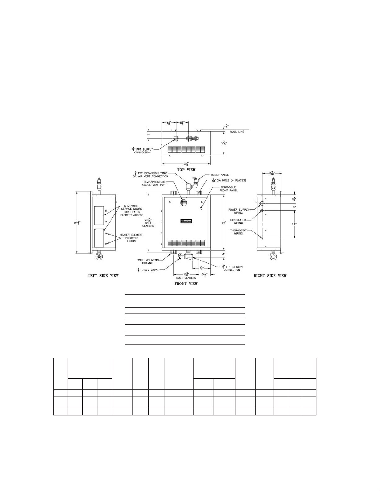
Figure 1: Dimensions and Specifi cations
2
Page 3
SECTION I: INSTALLATION INSTRUCTIONS
A. Inspect Shipment carefully for any signs of damage.
1. All equipment is carefully manufactured, inspected
and packed. Our responsibility ceases upon delivery
of Boiler to the carrier in good condition.
2. Any claims for damage or shortage in shipment
must be fi led immediately against the carrier by
the consignee. No claims for variances from,
or shortage in orders, will be allowed by Boiler
Manufacturer, unless presented within sixty (60)
days after receipt of goods.
B. Read These Instructions Carefully before proceeding
with installation and operation of the “CARE-FREE”
Electric Boiler.
1. The “CARE-FREE” is U.L. listed, constructed
and tested in accordance with the requirements of
the ASME Boiler and Pressure Vessel Code and
designed for use in any conventional hydronic
system except steam and gravity hot water.
2. The “CARE-FREE” Electric Boilers are shipped
completely assembled less circulator. All electrical
controls are mounted and wired in a compartment
immediately behind the Front Door of the Boiler
Jacket, see Figure 1.
C. Locate Boiler in or adjacent to the space to be heated
with consideration given to the location of the electrical
service. Although its compactness will allow the
“CARE-FREE” Electric Boiler to be mounted almost
anywhere – closet, alcove, or other small area, see
CLEARANCE REQUIREMENTS on Page 2.
D. Mount Boiler to wall using four 3/8" lag screws
or anchor bolts (depending upon wall construction)
passing through the holes provided in the wall
mounting channels. Figure 1 shows bolt center
dimensions. It is recommended that 1/2" plywood
be used as a base for mounting the boiler so that the
structure is adequate to carry the weight imposed upon
it – see Figure 1 for weight of boiler when full of water.
Boiler should be level for proper operation of BUILTIN AIR SEPARATOR.
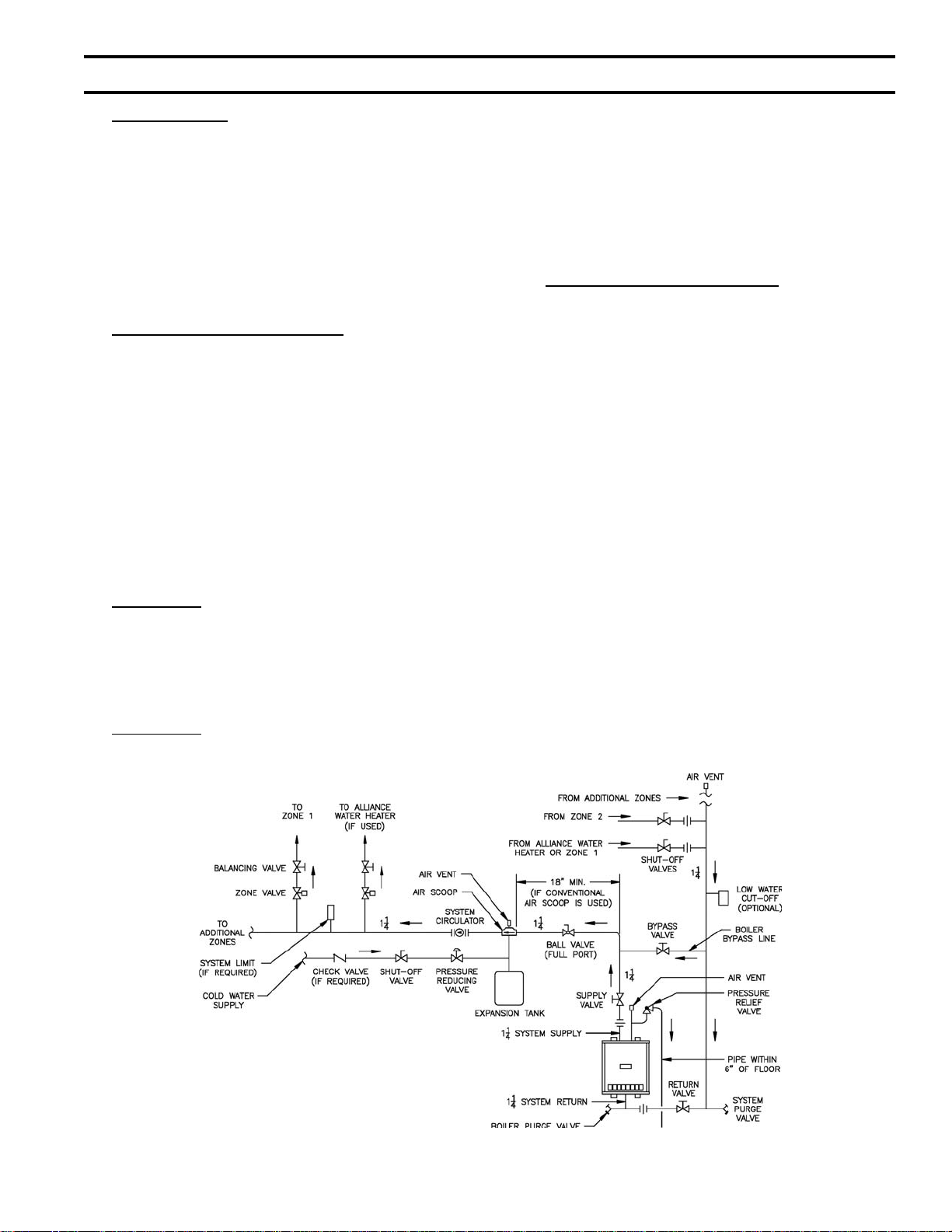
E. Connect Supply and Return Piping to Heating
System using standard recognized practices. See Figure
2. Install an appropriate size expansion tank in system
as per Figure 2. Do not connect into the 3/4" tee on top
of the boiler; instead install an automatic fl oat type air
vent at this point. Water content of the boiler is given
in Figure 1.
The relief valve outlet should be piped full size to a
drain or near the fl oor.
The heating elements are NOT compatible with
ethylene glycol based antifreeze.
If a low water cut-off is required, it must be mounted in
the system piping above the boiler.
The minimum safe water level of a hot water boiler is
just above the highest water containing cavity of the
boiler; that is, a hot water boiler must be full of water to
operate safely.
If it is required to perform a long term pressure test of
the hydronic system, the boiler should fi rst e isolated to
avoid a pressure test including the boiler, ALL trapped
air must fi rst be removed from the boiler.
A loss of pressure during such a test, with no visible
water leakage, is an indication that the boiler contained
trapped air.
Figure 2: Recommended Boiler Piping
3
Page 4

F. Install Electric Wiring in accordance with
NATIONAL ELECTRICAL CODE and Local
Regulations. The Burnham “CARE-FREE” Electric
Boilers may be used with 208 and 240 volt, 60 cycle,
single phase power and one 3 wire power supply. Since
the heaters are rated at 240 volts, however, any input
voltage less than this affects boiler capacity, see Figure
3.
To remove Front Door for access to terminal blocks and
controls:
1. CAUTION – make sure Electrical Service to Boiler
is disconnected.
2. Remove retaining screw at top of door.
3. Lower Door as far as possible, then push forward
until Hinge Pins in lower corners slide out of the
slots.
4. Raise one side of Door until Door will clear opening
– pull forward for removal.
Repeat above in reverse for replacing Door.
Provisions are provided in the right side of the boiler
jacket for power input, circulator, and thermostat
wiring, see Figure 1.
The power input legs are connected to the L1 and
L2 terminals on the terminal board on the control
compartment of the boiler. The neutral leg is connected
to the terminal marked N. Minimum recommended
wire sizes are shown in Figure 1. A separate grounding
conductor of at least #6AWG copper must be run to the
fi eld grounding lug on the control panel.
The Circulator is to be connected from its housing to
the terminals marked N and M on the Main Terminal
Block using Flexible Conduit, see Figures 2 and 4.
If the “QUICK CONNECT CIRCULATOR-PAK”
is ordered as Optional Equipment from the Boiler
Manufacturer, the Flexible Conduit for connecting the
circulator will be furnished.
G. A Prewired Low Voltage Control System is furnished
with every “CARE-FREE” boiler.
1. All controls are furnished in a compartment at the
front of the boiler for easy accessibility. In addition
to the Transformer used to power the system, are
the following: Circulator Relay, Heating Element
Sequencers (one per Heating Element), Dual High
Limit Control, Circulator Operation Selector Switch,
Circulator Fuse and Heating Element Relays.
2. If the Circulator Fuse is blown, power is interrupted
to the Transformer and hence, the control system
de-energized. This action prevents the Heating
Elements from coming on while the Circulator is
inoperative.
A Circulator Operation Selector Switch provides for
either Continuous or Intermittent Circulator operation.
With the switch in the “CONT.” position the Circulator
Delay Control will be bypassed and the Circulator will
operate continuously. The room Thermostat regulates
only the operation of the Heating Elements in the boiler.
With the Circulator Switch in the “INT.” position, the
Thermostat will operate both the Circulator and the
Heating Elements. Timing and wiring of the bimetal
heaters in the Circulator Relay and Sequencers assures
Circulator operation before and after Heating Elements
are energized and de-energized, respectively. The
Sequencers permit only one Heating Element at a time
(from bottom to top) to be energized thus preventing
a sudden inrush of electrical current. More detailed
operation is described in subsequent pages.
Wiring of a one zone system is shown in Figure 4.
Figures 5 and 6 show wiring for zoned systems, the
former when Zone Valves are used and the latter when
multiple Circulators are used.
Figure 3: Boiler Capacity at Various Voltages
4
Page 5

SECTION II: OPERATING AND SERVICE INSTRUCTIONS
A. Intermittent Circulator Operation
1. ROOM THERMOSTAT CLOSES
2. CIRCULATOR MOTOR ENERGIZED
a. As the thermostat closes its contacts, a low
voltage circuit (24V.) is completed to the bimetal
heater in the circulator relay (24A51). After
a time delay of 15 seconds, the main contacts
(120V.) of the circulator relay close to start the
circulator.
3. HEATING ELEMENT #1 ENERGIZED
a. Simultaneous with the completing of the circuit
for the circulator relay, two additional circuits
are completed.
b. The fi rst circuit is for the Heating Element
Relays which pull in immediately and the
second is for the bimetal heater in the #1 Heating
Element Sequencer (24A54).
c. These two circuits will be energized only if the
boiler is not “OFF” on limit.
d. After a time delay of 45 seconds (30 seconds
after the circulator has started) the main and
auxiliary contacts of the #1 Sequencer close;
the main contacts (240V.) energizing heating
element #1 and its pilot light (located at the
bottom of the side panel), the auxiliary contacts
(24V.) energizing the bimetal heater in the #2
Heating Element Sequencer.
4. HEATING ELEMENT #2 ENERGIZED
a. 45 seconds after bimetal heater in #2 Heating
Element Sequencer is energized, its main
contacts (240V.) and auxiliary contacts close;
the main contacts energizing heating element #2
and its pilot light (3
auxiliary contacts (24V.) energizing the bimetal
heater in the #3 Heating Element Sequencer.
5. HEATING ELEMENT #3 ENERGIZED
a. 45 seconds after bimetal heater in the #3 Heating
Element Sequencer is energized, its main
contacts and auxiliary contacts close; the main
contacts (240V.) energizing heating element #3
and its pilot light (2nd lowest in the boiler), the
auxiliary contacts (24V.) energizing the bimetal
heater in the #4 Heating Element Sequencer.
6. HEATING ELEMENT #4 ENERGIZED
a. 45 seconds after bimetal heater in #4 Heating
Element Sequencer is energized, its main
contacts and auxiliary contacts close, the main
contacts (240V.) energizing heating element #4
and its pilot light (highest in the boiler) – nothing
is connected to the auxiliary contacts.
rd
lowest in the boiler), the
7. ROOM THERMOSTAT OPENS
8. HEATING ELEMENTS DE-ENERGIZED
When the thermostat is satisfi ed and opens its
contacts, the low voltage circuits to the Heating
Element Relay and the Heating Element Sequencers
are broken. The Heating Element Relays “drop-out”
immediately and totally de-energize the Heating
Elements and pilot lights. After a time delay of 45
seconds, the main contacts of all the Sequencers
“break” thus resetting the Heating Element Relays.
9. CIRCULATOR MOTOR DE-ENERGIZED
Simultaneous with the breaking of the low voltage
circuit to the Heating Element Sequencers is the
breaking of the low voltage circuit to the Circulator
Relay by the opening of the thermostat contact.
After a time delay of 90 seconds after all Heating
Elements are “off” the bimetal heater opens the
main contacts in the Circulator Relay thus stopping
the circulator. When the boiler is zoned with
circulator and switching relays as illustrated in
Figure 6 on Page 8 the circulator switch must be in
the “constant” position; therefore the circulator will
not have any delay when the thermostat(s) closes or
opens its contacts.
B. Continuous Circulator Operation
If the Circulator Switch (located in the control portion
of the Boiler Jacket) is placed in the “CONT.” position,
the Circulator will run continuously and the Heating
Elements will sequence as in steps 3-6 and 8 above.
C. Dual Limit Operation
The Dual Limit Control consists of two independently
adjustable temperature limits. The left hand adjustment
is for the safety limit and should be set initially for
220°F. The lower right hand adjustment is for the
operating limit and should be set for 210°F with a
differential setting (upper right hand adjustment) of 10º.
These adjustments may be varied to suit the individual
installation, with minimum of 10° difference between
the limit settings. If the setting of the operating Limit
or the safety limit is reached, the Heating Elements only
will be de-energized; the Circulator will continue to
run. If the Circulator Switch is in the “INT.” position,
the Circulator runs until the thermostat is satisfi ed and
the main contacts on the Circulator Relay open.
GNINRAW
sireliobehtfonoitallatsnierofeB
ehtfonoitarepoeht,etelpmocderedisnoc
,dekcehcebdluohsslortnocreliob
timiLytefaS&gnitarepOehtylralucitrap
.slortnoC
5
Page 6

Figure 4: Wiring Diagram - Model E-4 Boilers
6
Page 7

D. Indicator Lights
There is an indicator light for each heating element.
If an indicator light is “on” it indicates its respective
heating element is energized. If the light is “off” it
indicates:
1. The heating element has not been energized.
2. The heating element sequencer is malfunctioning.
E. Built-In Air Eliminator
An air eliminator has been built into the top of the
electric boiler and a 3/4" tapping is provided with
nipple and tee for connection of Relief Valve and a fl oat
type Air Vent. See Figure 1.
Figure 5: Wiring Diagram - 3 Zone System
White-Rodgers 2 Wire Zone Valves
Figure 6: Wiring Diagram - 2 Zone System
Multiple Circulators
7
Page 8

Limited Warranty
FOR RESIDENTIAL CAST IRON WATER BOILERS
Subject to the terms and conditions set forth below, U.S. Boiler™
Co., Inc. Lancaster, Pennsylvania hereby extends the following limited
warranties to the original owner of a residential grade water boiler
manufactured and shipped on or after July 1,1991:
ONE YEAR LIMITED WARRANTY
ON RESIDENTIAL GRADE WATER BOILERS
U.S. Boiler Co., Inc. warrants to the original owner that its residential
grade water boilers comply at the time of manufacture with recognized
hydronic industry standards and requirements then in effect and will be
free of defects in material and workmanship under normal usage for a
period of one year from the date of original installation. If any part of a
water boiler is found to be defective in material or workmanship during
this one year period, U.S. Boiler Co., Inc. will, at its option, repair or
replace the defective part.
LIFETIME LIMITED WARRANTY ON HEAT EXCHANGER
U.S. Boiler Co., Inc. warrants to the original owner that the heat
exchanger of its residential grade water boilers will remain free from
defects in material and workmanship under normal usage for the
lifetime of the original owner at the original place of installation. If a
claim is made under this warranty during the fi rst ten years from the
date of original installation, U.S. Boiler Co., Inc. will, at its option, repair
or replace the heat exchanger. If a claim is made under this warranty
after the expiration of ten years from the date of original installation,
U.S. Boiler Co., Inc. will, at its option and upon payment of the pro-rated
service charge set forth below, repair or replace the heat exchanger.
The service charge applicable to a heat exchanger warranty claim is
based upon the number of years the heat exchanger has been in service
and will be determined as a percentage of the retail price of the heat
exchanger model involved at the time the warranty claim is made as
follows:
sraeY
ecivreSnI
egrahCecivreS
fo%sa
ecirPliateR
sraeY
ecivreSnI
egrahCecivreS
fo%sa
ecirPliateR
NOTE: If the heat exchanger model involved is no longer available due to
product obsolescence or redesign, the value used to establish the retail
price will be the published price as shown in the Burnham Hydronics
Repair Parts Price Sheet where the heat exchanger last appeared or the
current retail price of the then nearest equivalent heat exchanger.
ADDITIONAL TERMS AND CONDITIONS
1. Applicability: The limited warranties set forth above are extended
only to the original owner at the original place of installation within the
United States and Canada. These warranties are applicable only to
water boilers designated as residential grade by U.S. Boiler Co., Inc. and
installed in a single or two-family residence and do not apply to steam
boilers of any kind or to commercial grade boilers.
2. Components Manufactured by Others: Upon expiration of the
one year limited warranty on residential grade water boilers, all boiler
components manufactured by others but furnished by U.S. Boiler Co.,
Inc. (such as oil burner, circulator and controls) will be subject only to the
manufacturer’s warranty, if any.
3. Proper Installation: The warranties extended by U.S. Boiler Co., Inc.
are conditioned upon the installation of the residential grade water boiler
in strict compliance with U.S. Boiler Co., Inc. installation instructions. U.
S. Boiler Co., Inc. specifi cally disclaims liability of any kind caused by or
relating to improper installation.
4. Proper Use and Maintenance: The warranties extended by U.S. Boiler
Co., Inc. conditioned upon the use of the residential grade water boiler for
its intended purposes and its maintenance
01-111213141516171
oN
5015102520353
egrahC
81910212223242
0454055506560757
evoba
accordance with U. S. Boiler Co., Inc. recommendations and hydronics
industry standards. These warranties will be inapplicable if the residential
grade water boiler is used or operated over its rated capacity, is
subjected to unauthorized modifi cation, or is damaged as a result of
being otherwise improperly operated or serviced including, but not limited
to, damage from any of the following: operation with insuffi cient water,
allowing the boiler to freeze, subjecting the boiler to fl ood conditions, and
operation with unapproved water or fuel additives which cause deposits
or corrosion.
5. Removal and Installation: These warranties do not cover expenses
of removal or reinstallation. The owner is responsible for the cost of
removing and reinstalling any defective part and its replacements and all
labor and material connected therewith.
6. Exclusive Remedy: U.S. Boiler Co., Inc. obligation for any breach of
these warranties is limited to the repair or replacement of its parts in
accordance with the terms and conditions of these warranties.
7. Limitation of Damages: Under no circumstances shall U.S. Boiler Co.,
Inc. be liable for incidental, indirect, special or consequential damages
of any kind whatsoever under these warranties, including, but not limited
to, injury or damage to persons or property and damages for loss of use,
inconvenience or loss of time. U.S. Boiler Co., Inc. liability under these
warranties shall under no circumstances exceed the purchase price paid
by the owner for the residential grade water boiler involved. Some states
do not allow the exclusion or limitation of incidental or consequential
damages, so the above limitation or exclusion may not apply to you.
8. Limitation of Warranties: These warranties set forth the entire
obligation of U.S. Boiler Co., Inc. with respect to any defect in a
residential grade water boiler and U.S. Boiler Co., Inc. shall have no
express obligations, responsibilities or liabilities of any kind whatsoever
other than those set forth herein. These warranties are given in lieu of all
other express warranties.
ALL APPLICABLE IMPLIED WARRANTIES, IF ANY, INCLUDING
ANY WARRANTY OF MERCHANTABILITY OR FITNESS FOR A
PARTICULAR PURPOSE ARE EXPRESSLY LIMITED IN DURATION TO
A PERIOD OF ONE YEAR EXCEPT THAT IMPLIED WARRANTIES, IF
ANY, APPLICABLE TO THE HEAT EXCHANGER IN A RESIDENTIAL
GRADE WATER BOILER SHALL EXTEND TO THE ORIGINAL OWNER
dna52
FOR THE LIFETIME OF THE ORIGINAL OWNER AT THE ORIGINAL
PLACE OF INSTALLATION. SOME STATES DO NO ALLOW LIMITATION
ON HOW LONG AN IMPLIED WARRANTY LASTS, SO THE ABOVE
LIMITATION MAY NOT APPLY TO YOU.
PROCEDURE FOR OBTAINING WARRANTY SERVICE
In order to assure prompt warranty service, the owner is requested to
complete and mail the attached Warranty Card within ten days after the
installation of the boiler, although failure to comply with this request will
not void the owner’s rights under these warranties.
Upon discovery of a condition believed to be related to a defect in
material or workmanship covered by these warranties, the owner should
notify the installer, who will in turn notify the distributor. If this action is
not possible or does not produce a prompt response, the owner should
write to U.S. Boiler Co., Inc., Burnham Hydronics, at P.O. Box 3079,
Lancaster, PA 17604, giving full particulars in support of the claim.
The owner is required to make available for inspection by U.S.
Boiler Co., Inc. or its representative the parts claimed to be defective
and, if requested by U.S. Boiler Co., Inc. to ship these par ts prepaid to
U.S. Boiler Co., Inc. at the above address for inspection or repair. In
addition, the owner agrees to make all reasonable efforts to settle any
disagreement arising in connection with a claim before resorting to legal
remedies in the courts.
THIS WARRANTY GIVES YOU SPECIFIC LEGAL RIGHTS AND YOU
MAY ALSO HAVE OTHER RIGHTS WHICH VARY FROM STATE TO
STATE.
03/03
 Loading...