

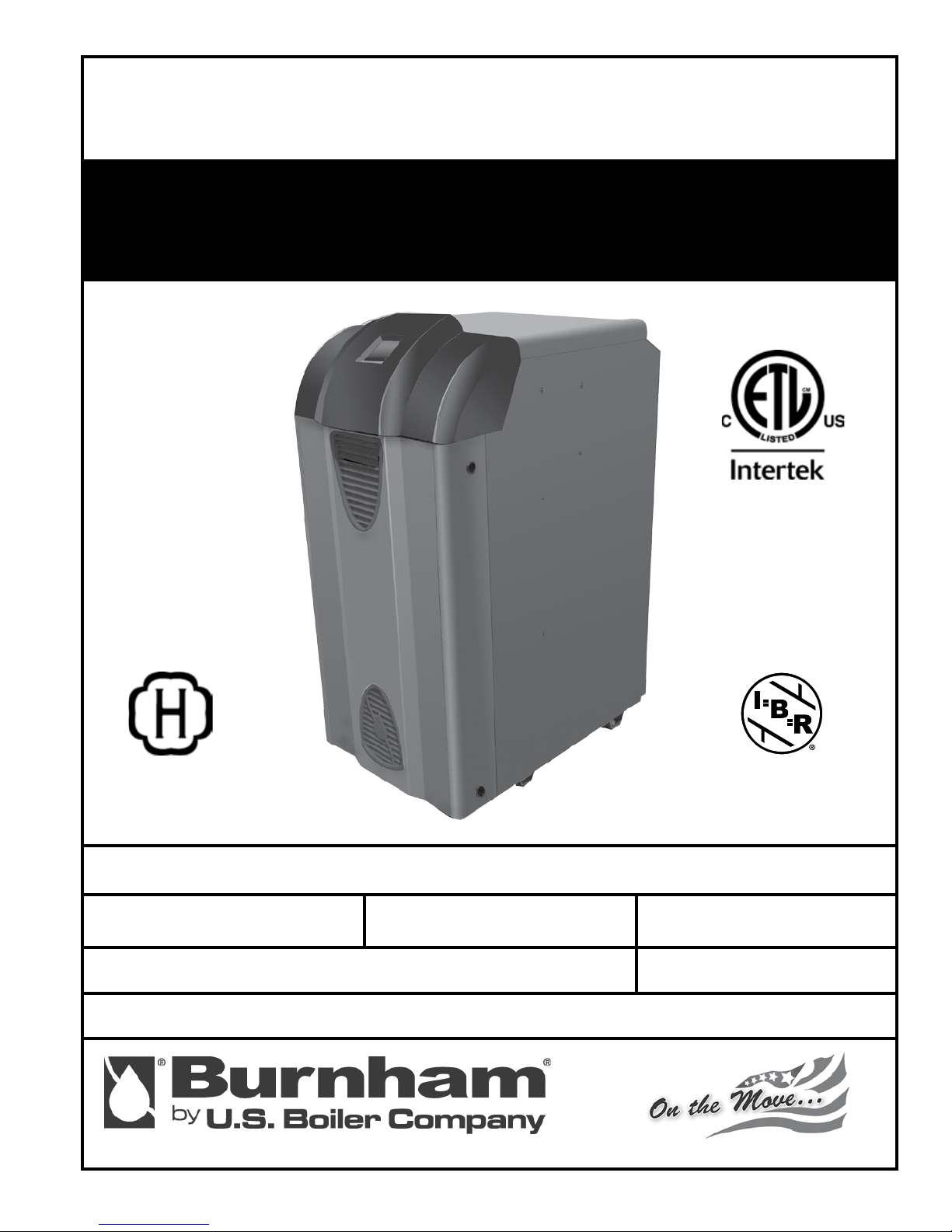
Burnham SERIES 3, ES2, 303, 304, 305 Installation, Operating And Service Instructions
...
INSTALLATION, OPERATING AND
SERVICE INSTRUCTIONS FOR
SERIES 3™
Gas - Fired Boiler
9700609
For service or repairs to boiler, call your heating contractor. When seeking information on boiler, provide
Boiler Model Number and Serial Number as shown on Rating Label.
Boiler Model Number
3 _ _
Heating Contractor Phone Number
Address
102998-01R1-7/10
Boiler Serial Number Installation Date
WARNINGS FOR THE HOMEOWNER
FOLLOW ALL INSTRUCTIONS and warnings
printed in this manual and posted on the boiler.
INSPECT THE BOILER ANNUALLY. To keep your
boiler safe and efcient, have a service technician
follow the Service checklist near the end of this
manual.
IF YOU ARE NOT QUALIFIED to install or service
boilers, do not install or service this one.
THE BOILER MAY LEAK WATER at the end of
its useful life. Be sure to protect walls, carpets,
and valuables from water that could leak from the
boiler.
PROTECT YOUR HOME IN FREEZING
WEATHER. A power outage, safety lockout, or
component failure will prevent your boiler from
lighting. In winter, your pipes may freeze and cause
extensive property damage. If you must leave
your home unattended for an extended time when
outdoor temperatures are below 32°F, rst turn off
your home’s main water supply and drain the water
from all pipes.
DO NOT BLOCK AIR FLOW into or around the
boiler. Insufcient air may cause the boiler to
produce carbon monoxide or start a re.
KEEP FLAMMABLE LIQUIDS AWAY from the
boiler, including paint, solvents, and gasoline.
The boiler may ignite the vapors from the liquids
causing explosion or re.
KEEP CHILDREN AND PETS away from hot
surfaces of the boiler, boiler piping, and vent pipe.
CARBON MONOXIDE (CO) is an odorless, deadly
gas that may be introduced into your home by
any malfunctioning fuel-burning product or vent
system failure. Consider installing CO alarms near
bedrooms in all levels of the building to warn you
and your family of potential CO exposure.
WARNINGS FOR THE INSTALLER
READ THIS ENTIRE MANUAL before attempting
installation, start-up, or service. Improper
installation, adjustment, alteration, service, or
maintenance may cause serious property damage,
personal injury, or death.
DO NOT DISCONNECT PIPE FITTINGS on the
boiler or in the heating system without rst verifying
that the system is cool and free of pressure and
that your clothing will protect you from a release
of hot water or steam. Do not rely solely on the
boiler’s temperature and pressure gage when
making this judgment.
USE PROPER PERSONAL PROTECTION
EQUIPMENT when servicing or working near the
boiler. Materials of construction, ue products, and
fuel contain alumina, silica, heavy metals, carbon
monoxide, nitrogen oxides, and/or other toxic or
harmful substances that can are hazardous to
health and life and that are known to the State of
California to cause cancer, birth defects, and other
reproductive harm.
INSTALL ALL GUARDS, cover plates, and
enclosures before operating the boiler.
SIZE THE BOILER PROPERLY relative to the
design heat load or, if using domestic hot water
priority, the peak hot water load, whichever
is larger. A grossly oversized boiler will cycle
excessively and this will lead to premature failure
of the boiler and its components. Our warranty
does not apply to damage from excessive cycling.
ADHERE TO ALL LOCAL CODE
REQUIREMENTS. Contact your local code
inspector prior to installation. In the absence of
a local code, adhere to the National Fuel Gas
Code ANSI Z223.1/NFPA 54 or CAN/CSA B149.1,
Natural Gas and Propane Installation Code.
ALL WIRING must comply with the National
Electrical Code ANSI/NFPA 70 (in the USA) or the
Canadian Electrical Code CSA C22.1 (in Canada)
and any local regulations.
2
5
2
1
3
4
Congratulations on your purchase of a new Burnham® boiler—designed and constructed to provide you
with years of reliable service.
•
Cast iron heat exchanger – for reliability and durability, nothing beats a cast iron heat exchanger.
Ours is made proudly by our foundry in Zanesville, Ohio.
•
IQ Control™ – the most advanced and easiest to use control available.
• System-friendly – built-in protection from condensation and thermal shock.
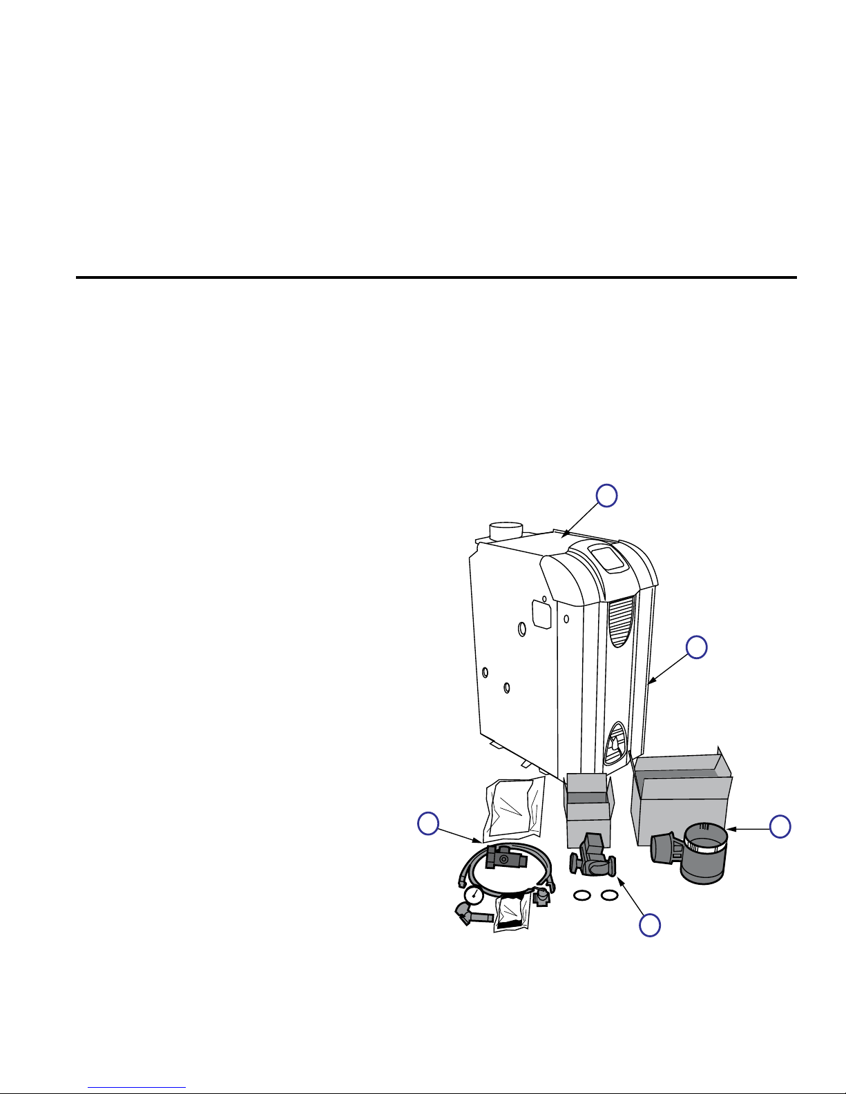
What's in the crate?
1. q Series 3™ Boiler
q Vent Damper w/ Carton
2.
4” Damper (102284-01)
5” Damper (102284-02)
6” Damper (102284-03)
7” Damper (102284-04)
8” Damper (102284-05)
3. q
Taco 007-2 (8056170)
Grundfos UP-15 (102805-01)
B & G NRF-22 (8056174)
4.
q Temperature/Pressure Gage; ¼” NPT
(100282-01)
Circulator & Gasket Kit
q Miscellaneous Parts Bag (102627-01)
5. q Instruction Envelope (102999-01)
q
Instruction & Operation Manual
(102998-01)
q
Hydronics Institute Instructions
(81460061)
q Boiler Warranty Sheet (102198-01)
q Equipment List (102996-01)
q Circulator Mounting Hardware Kit, 1-
1/4” NPT (6056007)
q Circulator Wiring Harness (6130701)
q
Drain Valve; ¾” NPT (806603012)
q Pressure Relief Valve; 30 psi
(81660363)
q Water Manifold for Pressure Relief/
Temp. Gage (80607001)
3

Ratings
SPECIFICATIONS
Series 3
Boiler Model
303 70 59 51 84
304 105 88 77 84
305 140 117 102 84
306 175 146 127 84
307 210 176 153 84
308 245 205 178 84
309 280 234 203 84
Input (MBH) DOE Heating Capacity (MBH) Net I=B=R Rating (MBH) AFUE (%)
Electrical Requirements: 120VAC, 60 Hz, 1-ph, 15A
Dimensions and Connections
Boiler
Model
303 33 12¾ 41 1¼ 1¼ 4 ½ ¾ ¾
304 33 15½ 41 1¼ 1¼ 5 ½ ¾ ¾
305 33 18½ 41 1¼ 1¼ 6 ½ ¾ ¾
306 33 21½ 41 1¼ 1¼ 6 ½ ¾ ¾
307 33 24¾ 41 1¼ 1¼ 7 ¾ ¾ ¾
308 33 27¾ 41 1¼ 1¼ 7 ¾ ¾ ¾
309 33 30¾ 41 1¼ 1¼ 8 ¾ ¾ ¾
Depth Width Height
Supply NPT
(inch)
Return NPT
(inch)
Vent
(inch)
Gas NPT
(inch)
Relief Valve
NPT (inch)
Drain
NPT (inch)
Water Temperatures and Flows
Allowable Supply
Boiler Model
Water Temperature
(°F)
303 130-220 110 None <1
304 130-220 110 None <1
305 130-220 110 None <1
306 130-220 110 None <1
307 130-220 110 None <1
308 130-220 110 None <1
309 130-220 110 None <1
Minimum Return
Water Temperature
(°F)
Weights and Volume
Boiler
Model
303 253 180 2
304 305 232 3
305 355 282 4
306 397 324 5
307 453 373 6
308 505 425 7
309 560 480 8
4
Shipping Weight
(lbs)
Empty Weight
(lbs)
Minimum Flow
Water Content
(gal)
(GPM)
Waterside Pressure Drop
at 20°F DT
(Ft. of Head)
SPECIFICATIONS (continued)
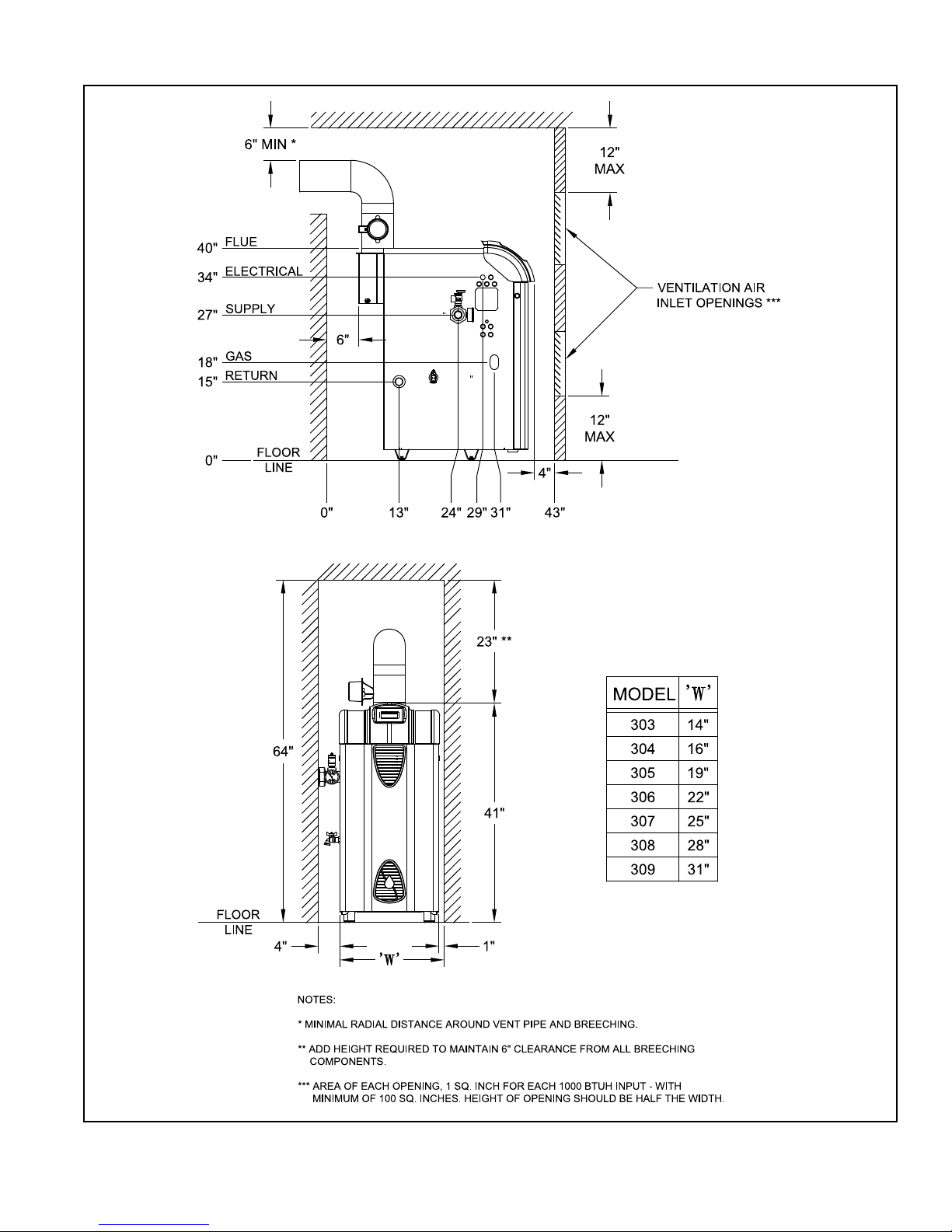
Figure S-1: Minimum Clearances to Combustibles and Closet Dimensions
5

BOILER QUICK-START
Installation:
1. Unpack the crate ............................................................................................. 7
2. Position the boiler ............................................................................................ 7
3. Provide combustion air .................................................................................... 8
4. Connect venting ............................................................................................... 9
5. Connect gas piping ........................................................................................ 10
6. Connect boiler water piping ........................................................................... 10
7. Connect electrical wiring ................................................................................ 12
8. Program the controls ..................................................................................... 13
9. Check for gas and water leaks ...................................................................... 15
10. Perform startup checks and adjustments ...................................................... 16
Annual Maintenance Checklist ............................................................................ 17
Troubleshooting ....................................................................................................
Repair Parts List ................................................................................................... 21
Internal Wiring ....................................................................................................... 27
18
Appendices:
A – Combustion Air.................................................................................................. 32
B – Venting .............................................................................................................. 33
C – Gas Piping ........................................................................................................37
D – System Piping ................................................................................................... 38
E – Filling the System and Checking for Leaks ....................................................... 44
F – Adjusting Gas Input Rate ..................................................................................45
G – Checking Draft and Combustion ....................................................................... 47
H – IQ Control System............................................................................................. 48
Warranty .................................................................................................. Back Cover
6
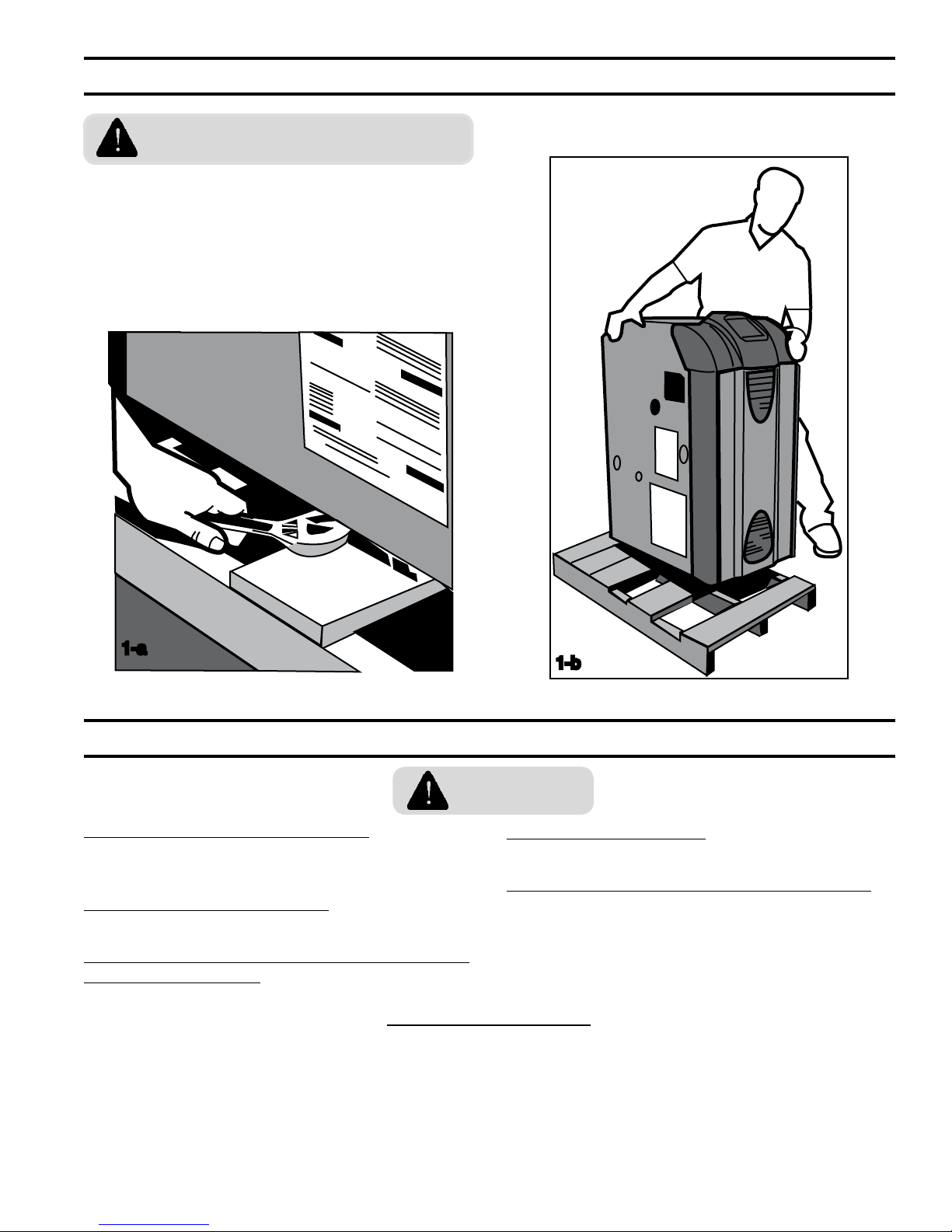
1. UNPACK THE CRATE
THE BOILER IS TOP-HEAVY. Do not
allow it to tip over.
1. Remove the sleeve.
2. Remove the contents from the skid, except
the boiler.
3. Remove the four (4) hex-drive lag screws
holding the boiler to the skid (Figure 1-a).
4. Tip the boiler and shimmy it off the skid.
1-a
2. POSITION THE BOILER
WARNINGS
OBSERVE MINIMUM CLEARANCES to
combustible walls and ceilings to avoid potential
re hazard.
DO NOT INSTALL ON CARPET. This may cause
a re.
INSTALLING THE BOILER NEAR A SOURCE OF
FLAMMABLE LIQUIDS or gases may cause re or
explosion.
1. Slide the boiler into desired location.
2. Meet the minimum clearances to
combustible construction per the
Specification Section of this manual.
1-b
CLEAN BURNERS DAILY if operating the boiler in
a dusty environment.
PROTECT IGNITION SYSTEM COMPONENTS
from sources of water that may spray, drip, or rain
on them during installation or service.
3. Allow 24" service clearance in front and on
the left side of the boiler.
4. Level the boiler, using shims as necessary.
7

3. PROVIDE COMBUSTION AIR
INSUFFICIENT COMBUSTION AIR
SUPPLY may result in the production and
release of deadly carbon monoxide (CO) into the
home which can cause severe personal injury or
death.
Like all fuel-burning appliances, boilers need air to
operate reliably and safely.
Provide combustion air using the instructions in
Appendix A—Combustion Air.
8
4. CONNECT VENTING
IMPROPER VENTING may result in
property damage and the release of ue
gases which contain deadly carbon monoxide (CO)
into the home, which can cause severe personal
injury, death or substantial property damage.
Inspect existing chimney before installing
boiler. Failure to clean or replace
perforated pipe or tile lining will cause severe
injury or death.
The vent system shall be designed and
constructed in accordance with NFPA 54 and
applicable local codes to develop a positive ow
adequate to convey ue or vent gases to the
outdoors, while ensuring that ue gases do not
cool prematurely.
Observe all general venting guidelines provided in
Appendix B—Venting. Additionally:
1. This appliance shall be vented into a listed
gas vent, masonry, metal, or factory-
built chimney as required by NFPA 54
and applicable local codes for Category I
appliances. If venting this appliance into
a masonry chimney, the chimney must be
lined with a listed chimney lining system as
required by NFPA 54 and applicable local
codes.
2. Attach the vent damper with three
sheetmetal screws around the perimeter of
the ue collar (Figure 4-a), oriented so that
the position indicator is visible. The vent
damper may also be mounted anywhere
between the ue outlet and the chimney
within reach of the electrical harness.
3. Vent connector shall meet the requirements
of NFPA 54 and applicable local codes.
Using sheetmetal screws, attach the vent
connector between the vent damper and the
vertical chimney (Figure 4-b).
4-a
DAMPER MUST BE OPEN when the main burner is ring.
4-b
9
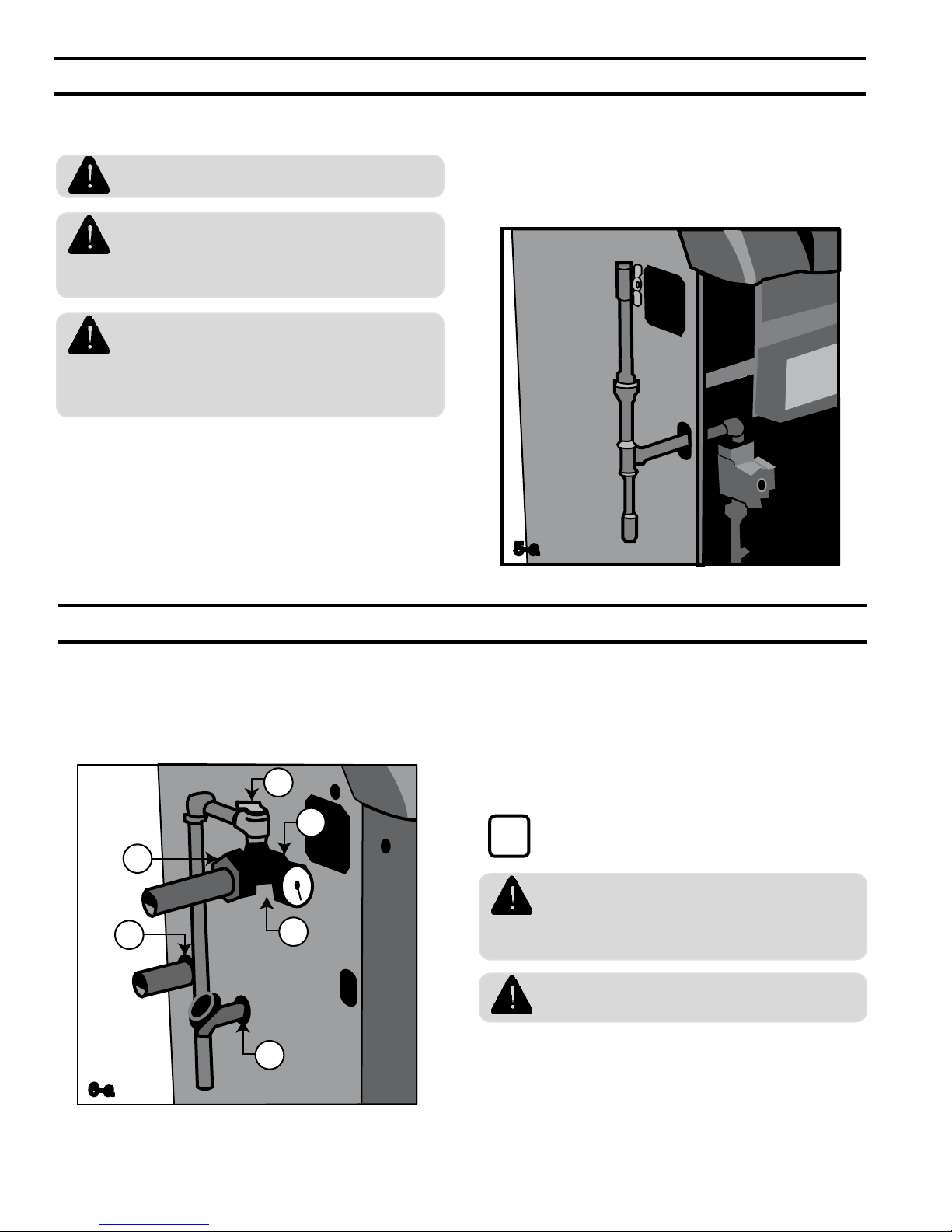
5. CONNECT GAS PIPING
RV
S
R
O
G
D
Size gas piping according to Appendix C – Gas
Piping
SHUT OFF GAS SUPPLY before
servicing the boiler.
ALL GAS PIPING MUST BE GAS
TIGHT. Use gas rated thread compound
on all threaded joints to avoid leaks, which may
result in re or explosion.
SIZE GAS PIPING, regulators, valves,
and meters so as to provide an adequate
gas ow and pressure to the boiler during
operation. Failure to do so may cause poor
combustion, noise, injury, or death.
1. Remove boiler door, locate gas valve and
remove plastic shipping plug.
2. Thread a ¾" x 1½" nipple, a 90°street
elbow, or a Honeywell ange onto the gas
valve and pipe through the slot in the left
jacket panel (Figure 5-a). In Canada, close
nipples and street ells are not approved for
use as gas piping.
3. Pipe through the left jacket panel, and
complete drip leg as shown (Figure 5-a).
5-a
6. CONNECT BOILER WATER PIPING
General system piping guidelines are included in
Appendix D—System Piping.
Additionally, for this particular boiler install piping
shown below (Figure 6-a).
6-a
1. Apply sealant to all threads.
10
2. Screw the water supply manifold into the
boiler outlet tapping “O.”
3. Orient the manifold with the relief valve on
top.
4. Screw the relief valve into manifold tapping
“RV”.
relief valve is installed.
to a location where it will not harm
people or damage property. The relief valve may
discharge scalding hot water or steam.
result in boiler explosion.
This installation is not complete until the
i
PIPE THE RELIEF VALVE DISCHARGE
BLOCKING THE RELIEF VALVE may
5. Screw the temperature-pressure gage into
manifold tapping “G”.
6. Connect the system supply to the open end
of the manifold "S" using a 1¼” male NPT
tting.
6. CONNECT BOILER WATER PIPING (continued)
7. Screw an installer-supplied 1¼” pipe or
nipple into the water return tapping “R”.
8. Screw the supplied drain valve into tapping
“D”.
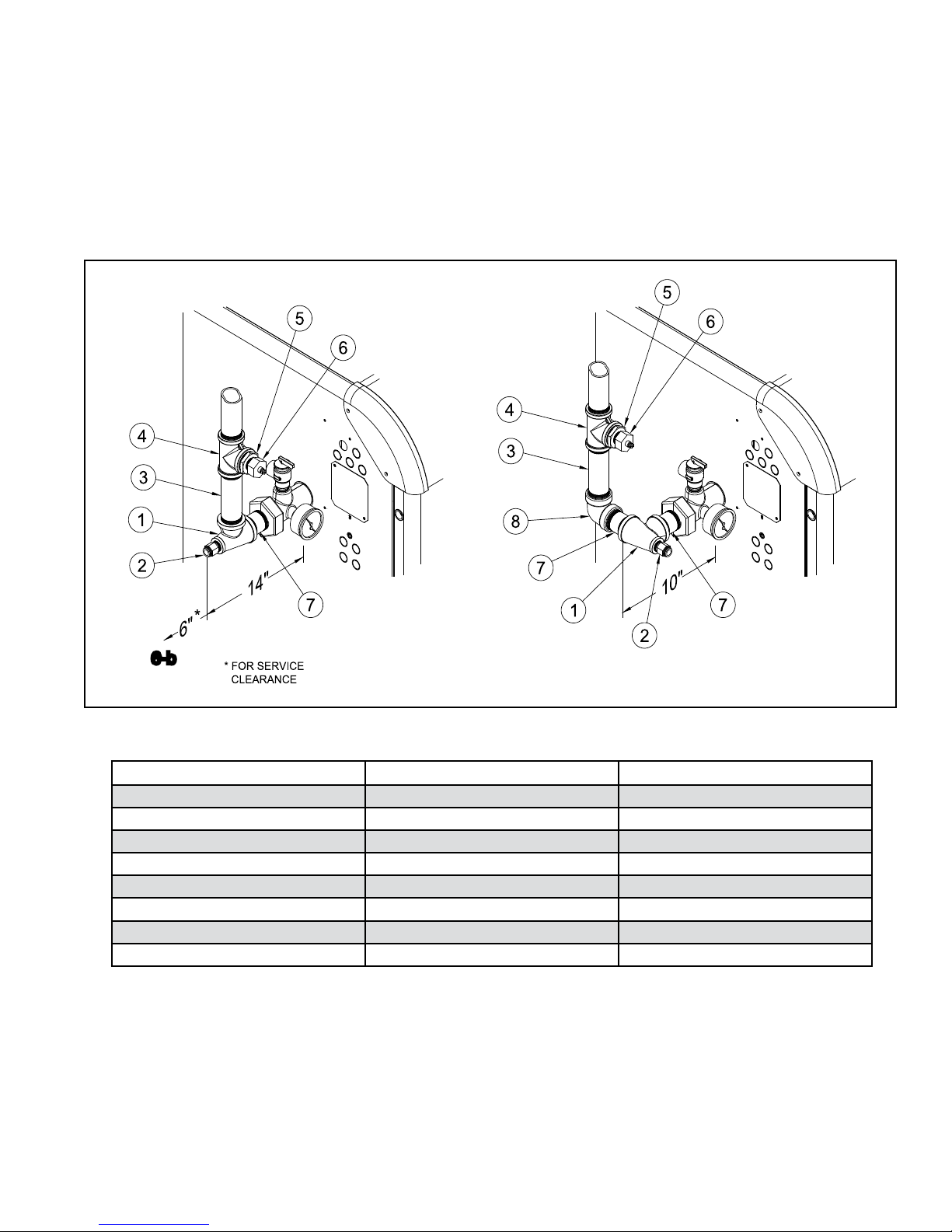
9. See Figure 6b for suggested near boiler
piping of IQ Options.
6-b
Item Description Burnham Part Number
1 1¼ x 1¼ x ½ Tee 806601021
2 Immersion Well, ½ NPT 80160456
3 1¼ x 6 Nipple 806600029
4 1¼ Tee 806601030
5 1¼ x ¾ Bushing 806600504
6 LWCO Sensor, ¾ NPT 102305-01
7 1¼ x 3 Nipple 806600005
8 1¼ Elbow 806601528
11
7. CONNECT ELECTRICAL WIRING
1
1
2
3 T
T
DISCONNECT ELECTRICAL POWER
to the boiler and heating system before
servicing. Positively assure that no voltage is
present. Lock electrical boxes to prevent someone
from inadvertently restoring power before the
heating system is safe to operate.
NEVER DEFEAT OR JUMP OUT safety
devices.
PROTECT EACH BOILER circuit with a
properly sized over-current protection
device.
MAKE ELECTRICAL CONNECTIONS
CAREFULLY according to the boiler’s
wiring diagram and instructions
Refer to the Internal Wiring diagrams later in this
manual.
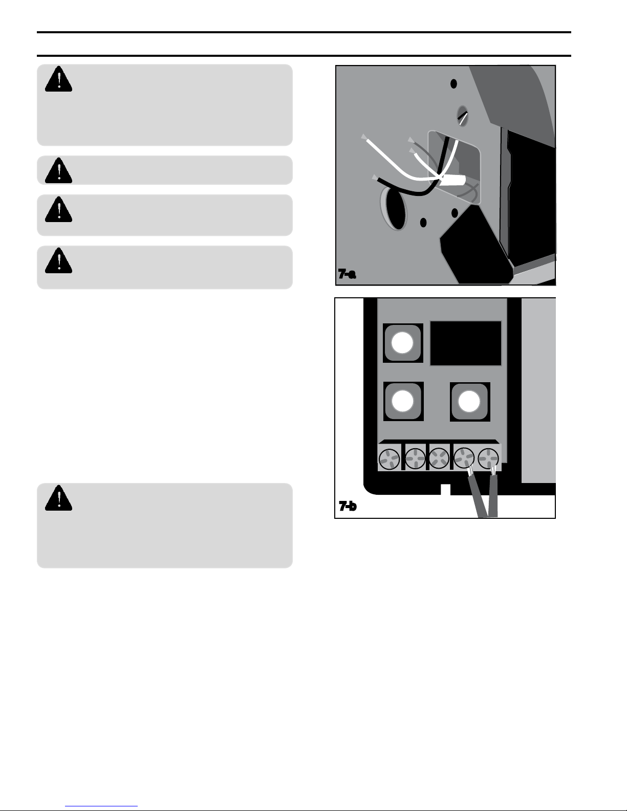
1. Locate the wiring box on the left side of the
boiler and open the cover (Figure 7-a).
2. Install a 120V disconnect near the boiler.
3. Connect the 120V wiring from the disconnect
to the boiler's white (neutral), black (hot),
and green (ground) labeled "120VAC Power
supply". Do not reverse polarity.
4. Connect the 120V wiring from the circulator
to the white (neutral) yellow (hot) wires
marked "circulator".
7-a
WIRE AN ADDITIONAL SAFETY LIMIT
such as a low water cutoff or temperature
limit device, other than an IQ™ Control device,
in series with the 120V circuit used to power the
boiler. Do not alter the boiler’s factory wiring when
adding an additional limit.
12
7-b
5. Connect the 24V wiring from the thermostat
to the "T-T" terminals on the Option Control
Panel.
6. To connect other external devices, refer to
the instructions included with these devices.
8. PROGRAM THE CONTROLS
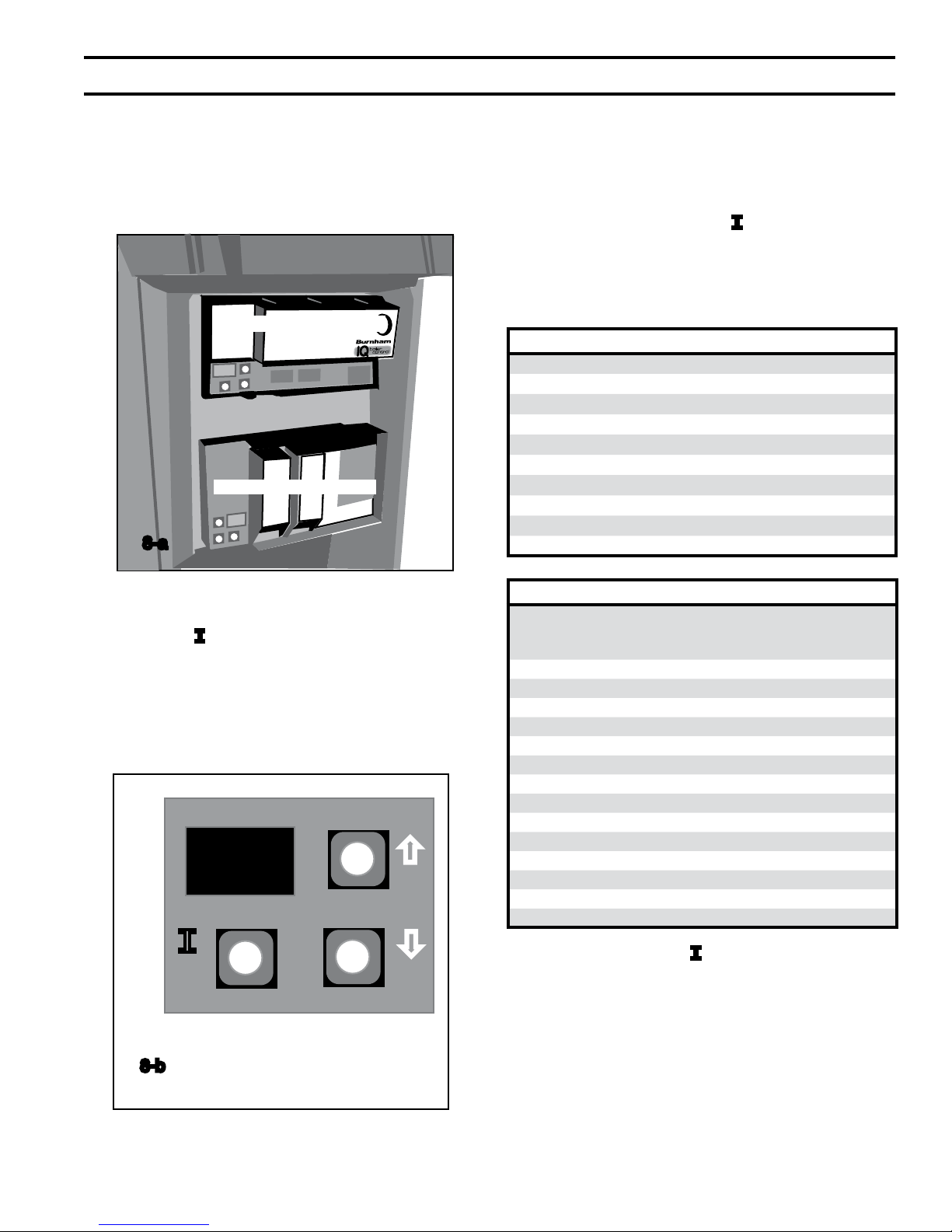
1
Using IQ Boiler Control Display
The IQ Boiler Control is located inside the boiler
front door, just above the IQ Option Panel (Figure
8-a).
IQ Boiler Control
IQ Option Panel
8-a
Viewing the Operating Mode Options
In operating mode the user may view (but not
change) boiler operating status, settings and
troubleshooting information. To view IQ Boiler
Control display information:
1. Press and release the “I” key on the IQ
Boiler Control to change from one parameter
to the next. Each setting will alternately ash
between the relevant display code and its
corresponding value.
Operating Mode Options
StA Status
bt Boiler Temperature
SP Operating Setpoint (Outdoor Reset)
HL High Limit Setting
HdF High Limit Differential
hr Heat Request Status
FLA Flame Current
rUn Run Time Hours
CYC Boiler Cycles
Err Error (see Error Numbers)
The IQ Boiler Control display, along with Up ñ,
Down ò, and “I” keys may be used to view boiler
operating status (Figure 8-b). Please note that
these keys look similar to the keys on the IQ
Option Panel but are in a different orientation, and
they perform different functions.
ñ
I
ò
IQ Boiler Control
8-b
Status Code Displayed in STA Mode
1 Standby:
Either TT Open or TT Closed and Boiler Temperature
within Setpoint & Differential with circulator running.
4 Prepurge
6 Spark
7 Flame Proving
8 Running
10 Retry/Recycle Delay
13 Soft Lockout
14 Hard Lockout
15 Waiting for Limit to Close
16 Flame Present Out of Sequence
17 Self Test
18 Waiting for Damper to Open
19 Waiting for Damper to Close
20 Damper Failure to Open
21 Damper Failure to Close
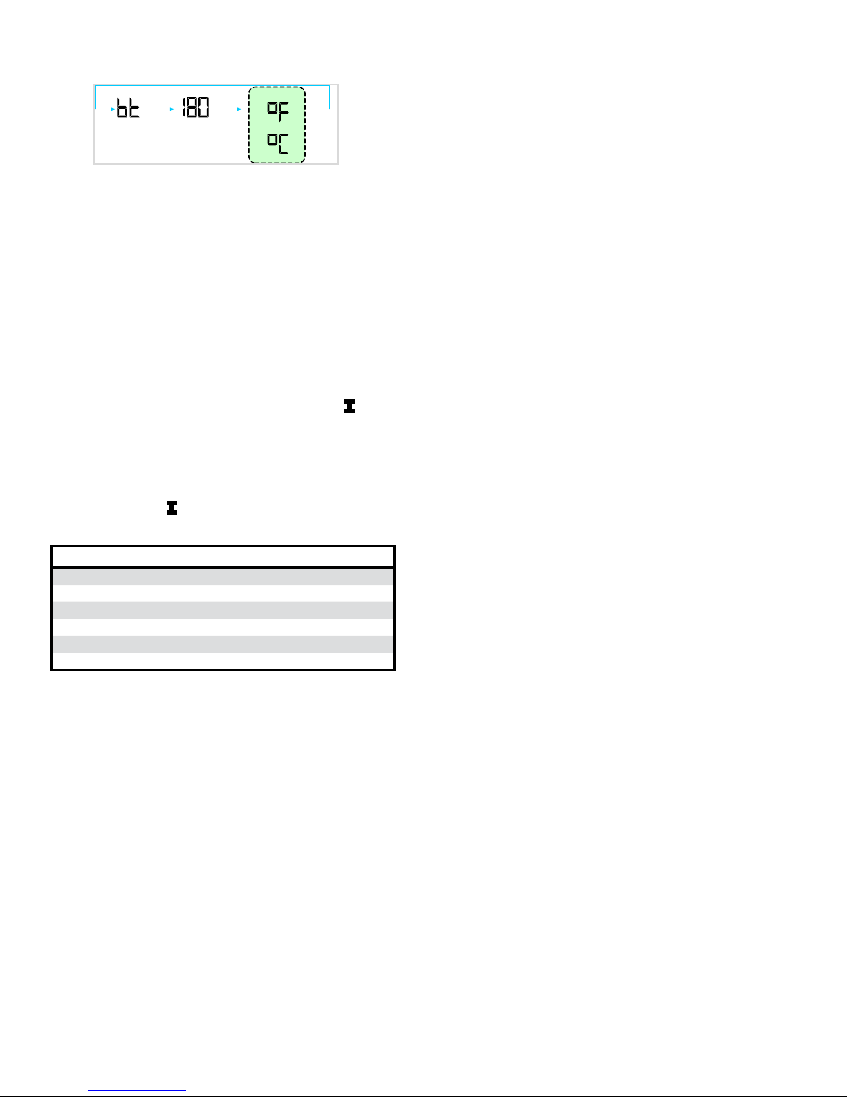
For example, when the “I” key is pressed on the
IQ Boiler Control until “bt” is displayed, it will then
ash a three digit number (such as “180”) followed
by either “F” (or “C”). This indicates that the boiler
water temperature is 180°F. Other operating
parameters display the information in a similar
fashion.
13
Unit D isplay
OR
Sample
Display
1 sec
1 sec
1 sec
8. PROGRAM THE CONTROLS (continued)
Please note that in operating mode to hold the
display on the value the user can press and hold
either the Up ñ or Down ò keys and the value
will be continuously shown. This may be helpful in
watching a value “live”.
Changing the Adjustable Parameters
To adjust the High Limit setpoint, High Limit
Differential or Pump Overrun time settings or
setting the display for either °F or °C temperature
readings:
1. Access the adjustment mode by pressing
and holding the Up ñ, Down ò, and “I”
keys simultaneously for three (3) seconds.
This procedure is intended to discourage
unauthorized changes or accidental changes
to limit settings.
2. Press the "I" key to display available
Adjustment Mode options. Select an option.
Adjustment Mode Options
HL_ Adjust High Limit Setting
dF_ Adjust High Limit Differential
Or_ Pump Overrun Time (minutes)
rst Reset Lockout
f-C Select degrees F or C Mode
bac Back to Operating Mode
3. Press the Up ñ and Down ò keys to adjust
the displayed setpoint to the desired value.
4. To return to the normal operating mode
from the Adjustment Mode, when the "bAc”
option is displayed, press either the Up ñ or
Down ò key. If no keys are pressed, after
ve (5) minutes the IQ Boiler Control will
automatically return to the Operating Mode.
More Information about Adjustable Parameters
1. High Limit (HL_)
The IQ Control is factory programmed
with a High Limit Setpoint of 180°F. The
boiler turns "off" when the supply water
temperature is above this value. The High
Limit setpoint is adjustable between 130°
and 220°F. The Operating Setpoint (SP) will
equal the High Limit Setpoint unless an IQ
Outdoor Reset IQ Option Card is installed.
The Outdoor Reset IQ Option Card reduces
the Operating Setpoint to regulate heat
delivery, increase home comfort and
save energy. Refer to the Appendix H for
additional information.
2. Differential (df_)
The IQ Boiler Control is factory programmed
with a Differential of 15°F. The Differential
is the number of degrees the supply
temperature must decrease below the
Operating Setpoint before the boiler can
restart. The differential is adjustable
between 10° through 30°F.
3. Pump Overrun Time (OR_)
The IQ Boiler Control is factory programmed
with a Pump Overrun Time of 0 minutes.
Pump Overrun Time (also called “off delay”
or “post purge”) continues pump operation
after a call for heat has ended, sending
excess heat from the boiler into the priority
zone. Ensure system piping and zone panel
settings allow water ow to the priority zone
after the call for heat ends. The Pump
Overrun Time is adjustable between 0
through 10 minutes.
Using the IQ Option Panel
IQ Option Cards are available from Burnham
distributors and are the simplest way to add
functionality, safety and efciency to your heating
system. The IQ Option Panel provides an easy and
convenient means to "plug-in" an Auxiliary High
Limit, Low Water Cut-off and/or Outdoor Reset
function.
For installation, programming, and troubleshooting
instructions, refer to the instructions supplied with
those cards.
14

8. PROGRAM THE CONTROLS (continued)
Using the Optional LCD Display Kit
The LCD Display is an easy to use touch screen
type display that allows a technician to monitor
and adjust the IQ Boiler Control and connected
IQ Option Cards. All boiler settings, status and
error codes are displayed in full text. All Outdoor
Reset IQ Option Card parameters are adjustable
with graphic and help information screens. The
LCD Display Kit includes a mounting bracket and
wiring harness to allow mounting in the Series 3
plastic hood above the front door. For installation,
programming, and troubleshooting instructions,
refer to the instructions supplied with the display.
9. CHECK FOR GAS AND WATER LEAKS
GAS LEAKS may result in re or
explosion.
WATER LEAKS may cause extensive
property damage.
Refer to Appendix E – Filling the System and
Checking for Leaks
15
10. PERFORM STARTUP CHECKS AND ADJUSTMENTS
FAILURE TO PERFORM THESE
CHECKS of the boiler's combustion and
safety systems may result in serious property
damage, injury, or death.
IF YOU SMELL GAS, STOP and repair
the leak. Lighting the boiler when gas is
leaking may cause explosion or re.
Follow the checklist below:
1. Verify that the venting, water piping, gas
piping, and electrical systems are properly
installed and checked.
2. Apply power to the boiler.
3. Adjust zone thermostat to maximum setting.
4. Allow gas line to purge of air.
10-b
q Boiler lights cleanly within 60 seconds.
5. Adjust gas input rate. See Appendix F
– Adjusting Gas Input Rate
10-a
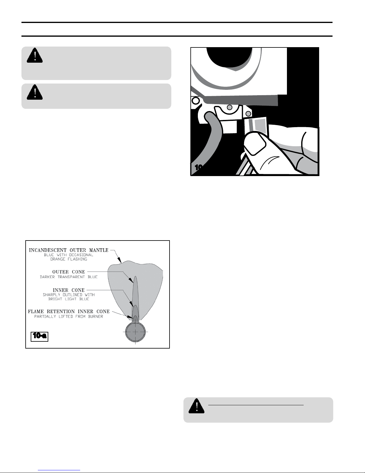
q Pilot and main burner flames appear
clean and blue.
6. Disconnect pilot lead wires from gas valve
(Figure 10-b).
q Boiler shuts off.
7. Reconnect pilot lead wires to gas valve.
q Boiler restarts.
8. Adjust zone thermostat to minimum setting.
q Boiler shuts off.
9. Adjust zone thermostat to maximum setting.
10. Observe temperature gage as boiler heats.
11. Adjust the high limit setting to its minimum
level (see "Programming High Limit" in
Section 8).
q Boiler shuts off when temperature gage
reads within 15°F of high limit setting.
12. Return high limit to the desired setting (see
"Programming High Limit" in Section 8).
13. Check draft. See Appendix G
– Checking Draft and Combustion.
q No spillage observed.
14. Check combustion in the vent stack and
record results in the spaces provided below.
_____ CO
_____ O
(less than 7%)
2
(more than 9%)
2
_____ CO (less than 100 ppm, air free)
ANY FAILED STARTUP CHECK
Must be corrected before placing the
boiler in service.
16
 Loading...