

Page 1
DNAGNITAREPO,NOITALLATSNI
ROFSNOITCURTSNIECIVRES
VP2SEIRES
TNEVREWOP
RELIOBDERIF-SAG
rebmuNledoMrelioB
____-I_VP_02
rotcartnoCgnitaeH
sserddA
8141775R23-10/05
nonoitamrofnignikeesnehW.rotcartnocgnitaehruoyllac,reliobotsriaperroecivresroF
bmuNlaireSdnarebmuNledoMrelioBedivorp,reliob
rebmuNlaireSrelioB
_______6
.lebaLgnitaRnonwohssare
etaDnoitallatsnI
rebmuNenohP
Price - $3.00
Page 2
The following terms are used throughout this manual to bring attention to the presence of hazards of various risk
levels, or to important information concerning product life.
REGNAD
suodrazahyltnenimminasetacidnI
tluserlliw,dediovatonfi,hcihwnoitautis
laitnatsbusroyrujnisuoires,htaedni
.egamadytreporp
.egamad
GNINRAW
suodrazahyllaitnetopasetacidnI
dluoc,dediovatonfi,hcihwnoitautis
royrujnisuoires,htaednitluser
reporplaitnatsbus
This Series 2PV Boiler has been approved by the Massachusetts Board of Plumbers and Gas Fitters: Approval No. G3-1200-28.
The Commonwealth of Massachusetts requires this product to be installed by a licensed Plumber or Gas Fitter.
.egamadyt
NOITUAC
suodrazahyllaitnetopasetacidnI
ytreporproyrujnironimroetaredomni
ECITON
nosnoitcurtsnilaicepssetacidnI
ecnanetniamro,noitarepo,noitallatsni
otdetalertontubtnatropmierahcihw
razahyrujnilanosrep
.sd
Table of Contents
tluseryam,dediovatonfi,hcihwnoitautis
I. Pre-Installation ........................4
II. Unpack Boiler ..........................5
III. Water Piping ............................6
IV. Gas Piping ................................8
V. Venting ......................................9
:lebal
VI. Electrical ................................15
VII. System Start-up .....................16
VIII. Service ....................................24
IX. Repair Parts ...........................26
X. Appendix
Low Water Cut Off ................35
ECITON
evahlevelaesevobateef000,2nahtretaergsedutitlatanoitallatsniroftliubsreliobASU
levelaesevobateef000,1reptnecrep4etartupnisagecuderotdecifiroyllaicepsneeb
.FxidneppAdna2.1.8noitceS,1.322ZISNA/45APFN,edoCsaGleuFlanoitaNehtrep
reliobedutitlahgiH.lebalgnitarehtnodetacidnisignizisecifiro'sreliobnaidanaC
gnitarehtnoxiffusrebmunledomehtnitigiddnocesehtybelbaifitnedierasledom
2__-I_VP_02noitavele.tf0002nahtsseL:
adanaC,noitavelerehgihdna.tf0002:4__-I_VP_02
ASU,noitavelerehgihdna.tf0002:5__-I_VP_02
2
Page 3
gnippihS.xorppA
).bl(thgieW
tnetnoCretaW
]snollaG[
]sehcnini[snoisnemiD
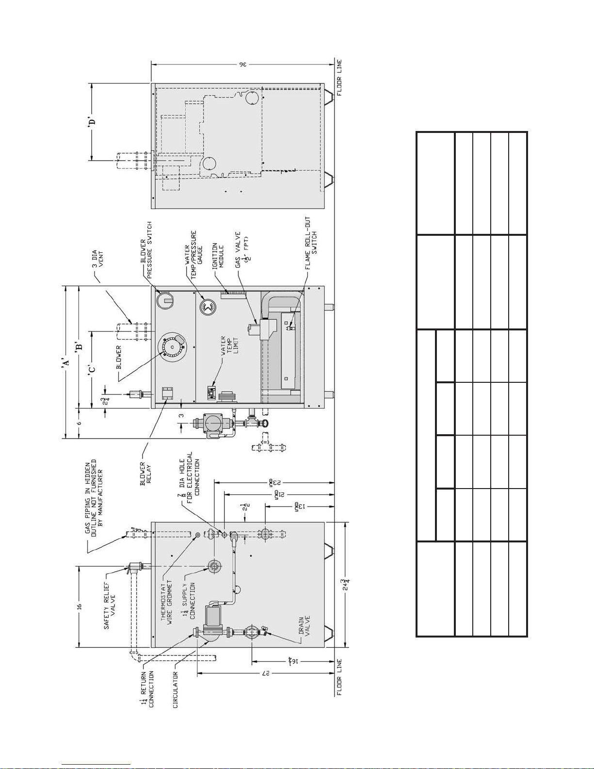
Figure 1: Elevation Views
ABCD
ledoMrelioB
VP302½02½4161/1-018/5-512.3562
VP602¼03¼428/1-51¼515.5914
VP5027212½31¼517.4753
VP402¾32¾71118/5-514 903
3
Page 4
I. Pre-Installation
GNINRAW
erofebsnoitcurtsnilladaerylluferaC
llawollofoteruliaF.reliobgnillatsni
esuacnacredroreporpnisnoitcurtsni
.htaedroyrujnilanosrep
A. Inspect shipment carefully for any signs of damage.
All equipment is carefully manufactured, inspected and
packed. Our responsibility ceases upon delivery of
boiler to carrier in good condition. Any claim for
damage or shortage in shipment must be fi led
immediately against carrier by consignee. No claims for
variances or shortages will be allowed by Boiler
Manufacturer, unless presented within sixty (60) days
after receipt of equipment.
B. Installation must conform to the requirements of the
authority having jurisdiction. In the absence of such
requirements, installation must conform to National
Fuel Gas Code, NFPA 54/ANSI Z223.1, and/or CAN/
CGA B149 Installation Codes. Where required by the
authority having jurisdiction, the installation must
conform to the Standard for Controls and Safety
Devices for Automatically Fired Boilers, ANSI/ASME
CSD-1.
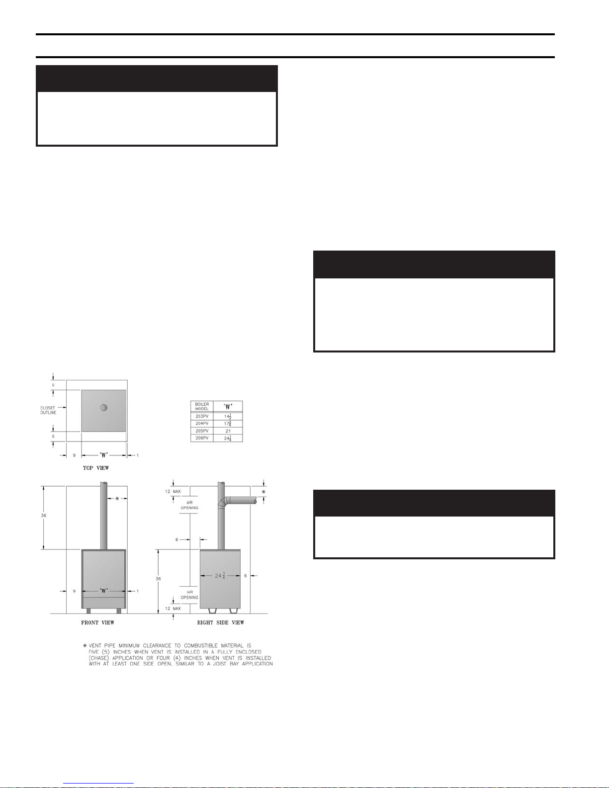
D. Provide clearance between boiler jacket and
combustible material in accordance with local fi re
ordinance. See Figure 2 for minimum clearance from
combustible material for closet installation. For alcove
installation provide top clearance of 27 inches and right
side clearance of 6 inches. Recommended service
clearance is 24 inches from left side, right side and
front. Service clearances may be reduced to minimum
clearances to combustible materials.
E. Install on level fl oor. For basement installation provide
solid base, such as concrete, if fl oor is not level or if
water may be encountered on fl oor around boiler.
F. Install near outside wall for through wall venting.
Refer to Section V: Venting, for vent length limitations.
GNINRAW
llatsnI.ecnailppaIIIyrogetaCsadeifitreC
noitceShtiwecnadroccanimetsystnev
yrnosamgnisutnevtonoD.gnitneV:V
rehtoro,tnevsagBepyT,yenmihc
.metsysgnitnevIyrogetaC
G. Protect gas ignition system components from water
(dripping, spraying, rain, etc.) during boiler operation
and service (circulator replacement, condensate trap,
control replacement, etc.).
Figure 2: Minimum Clearances to Combustible
Construction for Closet Installation
C. Appliance is design certifi ed for installation on
combustible fl ooring. The boiler must not be installed
on carpeting.
H. Provide combustion and ventilation air in accordance
with applicable provisions of local building codes, or
National Fuel Gas Code, NFPA 54/ANSI Z223.1,
Section 5.3, Air for Combustion and Ventilation, or
Sections 7.2, 7.3 or 7.4 of CAN/CGA B149 Installation
Codes.
GNINRAW
rianoitalitnevdnanoitsubmocetauqedA
reporperussaotdedivorpebtsum
.noitsubmoc
The following guideline is based on the National Fuel
Gas Code, NFPA 54/ANSI Z223.1.
1. Determine volume of space (boiler room). Rooms
communicating directly with space (through
openings not furnished with doors) are considered
part of space.
Volume [ft³] = Length [ft] x Width [ft] x Height [ft]
2. Determine Total Input of all appliances in space.
Round result to nearest 1,000 Btu per hour (Btuh).
3. Determine type of space. Divide Volume by Total
Input.
4
Page 5

a. If result is greater than or equal to 50 ft³ per
1,000 Btuh, space is considered an unconfi ned
space.
b. If result is less than 50 ft³ per 1,000 Btuh, space
is considered a confi ned space.
4. Determine building type. A building of unusually
tight construction has the following characteristics:
a. Walls and ceiling exposed to outside atmosphere
have a continuous water vapor retarder with a
rating of 1 perm or less with openings gasketed
and sealed, and;
b. Weather-stripping has been added on openable
windows and doors, and;
c. Caulking or sealants applied in joints around
window and door frames, between sole plates
and fl oors, between wall-ceiling joints, between
wall panels, at plumbing and electrical
penetrations, and at other openings.
5. For boiler located in an unconfi ned space in a
building of other than unusually tight construction,
adequate combustion and ventilation air is normally
provided by fresh air infi ltration through cracks
around windows and doors.
6. For boiler located within unconfi ned space in
building of unusually tight construction or within
confi ned space, provide outdoor air through two
permanent openings which communicate directly or
by duct with the outdoors or spaces (crawl or attic)
freely communicating with the outdoors. Locate one
opening within 12 inches of top of space. Locate
remaining opening within 12 inches of bottom of
space. Minimum dimension of air opening is 3
inches. Size each opening per following:
a. Direct communication with outdoors. Minimum
free area of 1 square inch per 4,000 Btu per hour
input of all equipment in space.
b. Vertical ducts. Minimum free area of 1 square
inch per 4,000 Btu per hour input of all
equipment in space. Duct cross-sectional area
shall be same as opening free area.
c. Horizontal ducts. Minimum free area of 1 square
inch per 2,000 Btu per hour input of all
equipment in space. Duct cross-sectional area
shall be same as opening free area.
Alternate method for boiler located within confi ned
space. Use indoor air if two permanent openings
communicate directly with additional space(s) of
suffi cient volume such that combined volume of all
spaces meet criteria for unconfi ned space. Size each
opening for minimum free area of 1 square inch per
1,000 Btu per hour input of all equipment in spaces,
but not less than 100 square inches.
7. Ventilation Duct Louvers and Grilles. Equip outside
openings with louvers to prevent entrance of rain
and snow, and screens to prevent entrance of insects
and rodents. Louvers and grilles must be fi xed in
open position or interlocked with equipment to open
automatically before burner operation. Screens must
not be smaller than ¼ inch mesh.
Consider the blocking effect of louvers, grilles and
screens when calculating the opening size to provide
the required free area. If free area of louver or grille
is not known, assume wood louvers have 20-25
percent free area and metal louvers and grilles have
60-75 percent free area.
I. Do not install boiler where gasoline or other
fl ammable vapors or liquids, or sources of hydrocarbons
(i.e. bleaches, cleaners, chemicals, sprays, paint
removers, fabric softeners, etc.) are used or stored.
NOITUAC
tnemnorivnenanireliobsihtgnitarepodiovA
yrd,srebifnoitalusniesool,tsudwaserehw
sireliobfI.tneserpera.cte,tsudllaw
renrubeht,snoitidnocesehtrednudetarepo
dnadenaelcebtsumstropdnaroiretni
.noitareporeporperusniotyliaddetcepsni
II. Unpack Boiler
NOITUAC
.roolftsniagatekcaj
A. Move boiler to approximate installed position.
B. Remove all crate fasteners.
C. Lift outside container and remove with all other inside
protective spacers and bracing. Save two of the
wooden slats from the container sleeve for use in
Paragraphs E and F.
D. Remove all boiler hold-down fasteners.
reliobpmubtonoD.reliobpordtonoD
E. Tilt the boiler to one side and slide a wooden slat under
the two raised feet.
F. Tilt the boiler to the other side and slide another
wooden slat under the two raised feet.
G. Slide the boiler forward or backward off the skid using
the two wooden slats as runners.
H. Move boiler to its permanent location.
5
Page 6
III. Water Piping and Trim
NOITUAC
.gnidliub
A. Design and install boiler and system piping to
prevent oxygen contamination of boiler water.
NOITUAC
lliwretawreliobfonoitanimatnocnegyxO
reliobleetsdnanorifonoisorrocesuac
tonseodytnarrawdradnatss'mahnruB
negyxoybdesuacsmelborprevoc
.retawreliobfonoitanimatnoc
Oxygen contamination sources are system leaks
requiring addition of makeup water, fi ttings, and
oxygen permeable materials in distribution system.
Eliminate oxygen contamination by repairing system
leaks, repairing fi ttings, and using nonpermeable
materials in distribution system.
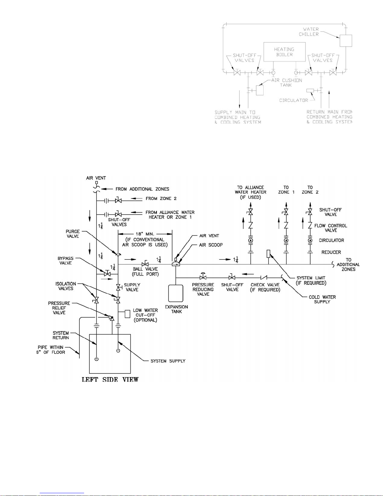
B. Connect system supply and return piping to boiler.
See Figure 4A or 4B. Also consult I=B=R Installation
and Piping Guides. Maintain minimum ½ inch
clearance from hot water piping to combustible
materials.
C. Install Circulator with fl anges, gaskets and bolts
provided. Five foot circulator harness allows circulator
to be mounted on supply or return. Connect harness to
circulator and secure any excess conduit.
D. Install Safety Relief Valve. See Figure 4A or 4B.
Safety Relief Valve must be installed with spindle in
vertical position. Installation of the relief valve must be
consistent with the ANSI/ASME Boiler and Pressure
Vessel Code, Section IV.
GNINRAW
folaitnetopetanimileotroolfraendepip
aeraynaniepiptonoD.snrubereves
llatsnitonoD.ruccodluocgnizeerferehw
.sevlavffo-tuhsyna
E. Install Drain Valve in ¾" NPT connection in tee
provided. See Figure 1.
F. Space heating and domestic water heating with
Alliance water heater. Install Alliance water heater as a
nitluseryamreliobepipylreporpoteruliaF
roreliobotegamaddnanoitareporeporpmi
separate heating zone. Refer to Alliance Installation,
Operating and Service Instructions for additional
information.
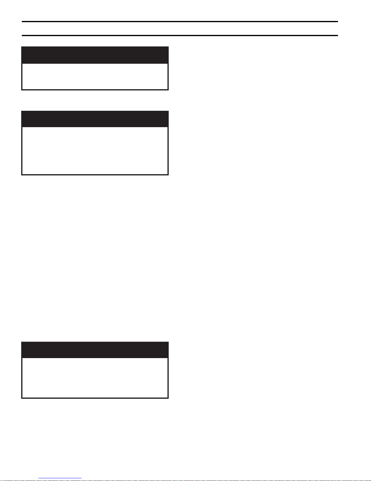
G. If boiler is used in connection with refrigeration
systems, boiler must be installed with chilled medium
piped in parallel with the heating boiler using
appropriate valves to prevent chilled medium from
entering boiler, see Figure 3. Also consult I=B=R
Installation and Piping Guides.
H. If boiler is connected to heating coils located in air
.eruliafreliobotdaelnacdna,stnenopmoc
handling units where they may be exposed to
refrigerated air, boiler piping must be equipped with
fl ow control valves to prevent gravity circulation of
boiler water during operation of cooling system.
I. Use a boiler bypass if the boiler is to be operated in a
system which has a large volume or excessive radiation
where low boiler water temperatures may be encountered (i.e. converted gravity circulation system, etc.).
Install pipe tee between circulator and boiler return
along with second tee in supply piping as shown in
Figure 4A or 4B. Bypass should be same size as the
supply and return lines with valves located in bypass
and supply outlet as illustrated in Figure 4A or 4B in
order to regulate water fl ow to maintain higher boiler
water temperatures.
After the boiler is operational (reference Section VII.
System Start-Up) set by-pass and boiler supply valves
to half throttle position to start. Operate boiler until
system water temperature reaches normal operating
range.
Adjust valves to provide 180° to 200°F supply water
temperature. Opening the boiler supply valve will raise
system temperature, while opening the by-pass valve
will lower system supply temperature.
J. A hot water boiler installed above radiation level
must be provided with a low water cut-off device as
part of installation.
If a low water cut-off is required, it must be mounted in
ebtsumgnipipegrahcsidevlavfeilerytefaS
the system piping above the boiler.
The minimum safe water level of a hot water boiler is
just above the highest water containing cavity of the
boiler; that is, a hot water boiler must be full of water to
operate safely.
Refer to Section X for low water cut-off piping and
wiring instructions.
K. If it is required to perform a long term pressure test of
the hydronic system, the boiler should fi rst be isolated
to avoid a pressure loss due to the escape of air trapped
in the boiler.
6
Page 7
To perform a long term pressure test including the
boiler, ALL trapped air must fi rst be removed from the
boiler.
A loss of pressure during such a test, with no visible
water leakage, is an indication that the boiler contained
trapped air.
L. Oil, grease, and other foreign materials which
accumulate in new hot water boilers and a new or
reworked system should be boiled out, and then
thoroughly fl ushed. A qualifi ed water treatment
chemical specialist should be consulted for
recommendations regarding appropriate chemical
compounds and concentrations which are compatible
with local environmental regulations.
M. After the boiler and system have been cleaned and
fl ushed, and before refi lling the entire system add
appropriate water treatment chemicals, if necessary, to
bring the pH between 7 and 11.
Figure 3: Recommended Piping for Combination
Heating & Cooling (Refrigeration) Systems
Figure 4A: Boiler Piping for Circulator Zoned Heating System
7
Page 8
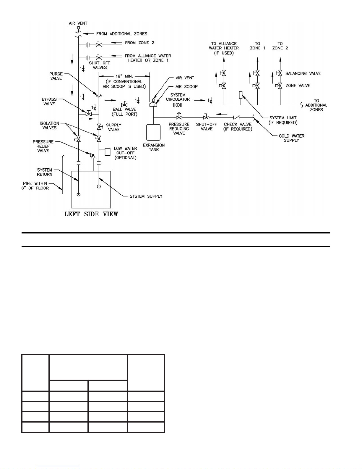
IV. Gas Piping
Figure 4B: Boiler Piping for Zone Valve Zoned Heating Systems
A. Size gas piping. Design system to provide adequate gas
supply to boiler. Consider these factors:
1. Allowable pressure drop from point of delivery to
boiler. Maximum allowable system pressure is ½
psig. Actual point of delivery pressure may be less;
contact gas supplier for additional information.
Minimum gas valve inlet pressure is listed on rating
label.
2. Maximum gas demand. Table 1 lists boiler input
rate. Also consider existing and expected future gas
utilization equipment (i.e. water heater, cooking
equipment).
Table 1: Rated Input
saGlarutaNenaporP/PL
etaRtupnI
]ruohrepteefcibuc[
saG
noitcennoC
eziS
relioB
ledoM
rebmuN
VP30226¾42½
VP40269½83½
VP50203125½
VP602461¾56½
3. Length of piping and number of fi ttings. Refer to
Table 2 for maximum capacity of Schedule 40 pipe.
Table 3 lists equivalent pipe length for standard
fi ttings.
4. Specifi c gravity of gas. Gas piping systems for gas
with a specifi c gravity of 0.70 or less can be sized
directly from Table 2, unless authority having
jurisdiction specifi es a gravity factor be applied. For
specifi c gravity greater than 0.70, apply gravity
factor from Table 4. If exact specifi c gravity is not
shown choose next higher value.
For materials or conditions other than those listed
above, refer to National Fuel Gas Code, NFPA 54/
ANSI Z223.1, or size system using standard
engineering methods acceptable to authority having
jurisdiction.
B. Connect boiler gas valve to gas supply system.
1. Use methods and materials in accordance with local
plumbing codes and requirements of gas supplier. In
absence of such requirements, follow National Fuel
Gas Code, NFPA 54/ANSI Z223.1 and/or CAN/
CGA B149 Installation Codes.
2. Use thread (joint) compounds (pipe dope) resistant
to action of liquefi ed petroleum gas.
8
Page 9
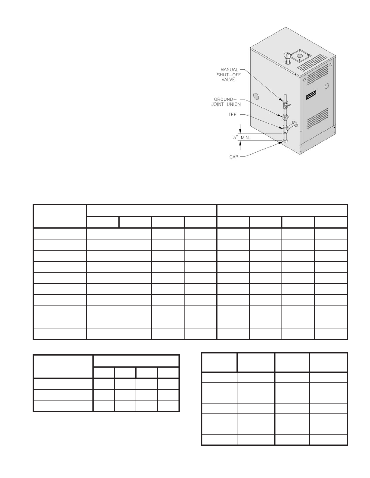
3. Install sediment trap, ground-joint union and manual
shut-off valve upstream of boiler gas control valve
and outside jacket. See Figure 6.
4. All above ground gas piping upstream from manual
shut-off valve must be electrically continuous and
bonded to a grounding electrode. Do not use gas
piping as grounding electrode. Refer to National
Electrical Code, ANSI/NFPA 70 and/or CSA C22
Electrical Code.
C. Pressure test. The boiler and its gas connection must
be leak tested before placing boiler in operation.
1. Protect boiler gas control valve. For all testing over
½ psig, boiler and its individual shut-off valve must
be disconnected from gas supply piping. For testing
at ½ psig or less, isolate boiler from gas supply
piping by closing boiler's individual manual shut-off
valve.
2. Locate leaks using approved combustible gas
detector, soap and water, or similar nonfl ammable
solution. Do not use matches, candles, open fl ames,
or other ignition source.
Table 2: Maximum Capacity of Schedule 40 Pipe in CFH For Gas Pressures of 0.5 psig or Less
Figure 6: Recommended Gas Piping
htgneL
]teeF[
01231872025050,1571063086004,1
0229091053037021052564059
033725158209579002573077
043603154200528071023066
056551151204437151582085
060550159100466831062035
07646908107316521042094
08340907105375811022064
09044806102335011502034
001839705150305301591004
Table 3: Fitting Equivalent Lengths
gnittiF
llE°547.012.16.1
llE°096.11.26.25.3
½¾ 1 ¼1½¾1¼1
½¾ 1 ¼1
)woblEsA(eeT1.31.42.59.6
porDerusserP.c.whcni3.0 porDerusserP.c.whcni5.0
Table 4: Specifi c Gravity Correction Factors
eziSepiPlanimoN
cificepS
ytivarG
05.001.103.170.1
55.040.104.140.1
06.000.105.100.1
56.069.006.179.0
noitcerroC
rotcaF
cificepS
ytivarG
noitcerroC
rotcaF
07.039.007.149.0
57.009.0
08.078.0
9
Page 10
V. Venting
GNINRAW
®
C4-92LAnonrehtoyna
.smetsystnevdesab
.reliobsihthtiwdoohtfardrorepmadcirtemorabaesutonoD
rocillatemnon,leetssselniats613epyTro403epyT,dezinavlaghtiwreliobsihtesutonoD
D
.reliobsihthtiwsrepmadtnevesutono
,noitaroiretedtneverpoT.noitanimretdnuorasecafrusnomrofyamecidnaerutsioM
doogniebdluohssecafrus
.).cte,detniap,delaes(riaper
snoisivorperaerehtosdellatsniebtsumdnanoitarepoefasrofriahserfsdeenreliobsihT
.r
ianoitalitnevdnanoitsubmocetauqedarof
arepotonoD
fosecruosro,sdiuqilrosropavelbammalfrehtoroenilosagerehwreliobet
,srenetfoscirbaf,srevomertniap,syarps,slacimehc,srenaelc,sehcaelb.e.i(snobracordyh
tneserpro/dnaderots,desuera).cte
.riaehtni
.teeftnelaviuqe52fohtgneltnevmumixamdeecxetonoD
Table 5: Burnham Vent System Components
mahnruB
metsyStneV
tnenopmoC
tF1xepiP.aiD"3U6926118
tF3xepiP.aiD"3U8926118
tF5xepiP.aiD"3U0036118
elbatsujdAxepiP.aiD"3U9136118
iD"3U4926118
woblE°09.a
woblE°54.aiD"3U2926118
eeTniarDlatnoziroH.aiD"3U2036118
eeTniarDlacitreV.aiD"3U4036118
mahnruB
rebmuNtraP
10
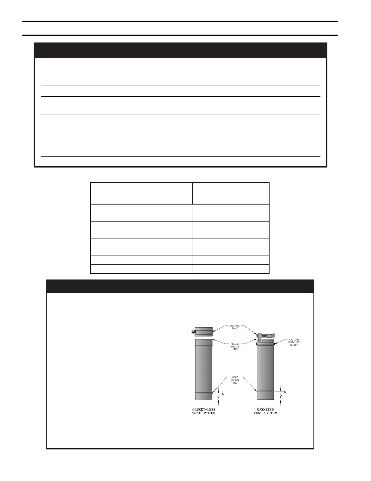
ECITON
hcaednanidesahpgnieberaAerugiFniwolebderutcipstnenopmocmetsystnevdeteksagehT
gnitnevssel-teksagdeilppusylsuoiverpehthtiwelbaegnahcretnisitnenopmoctnev
odyehtsa,niojotreisaednarekciuqyllarenegerastnenopmoctnevrewenehT.stnenopmoc
.dehcattaerasdnabpmalcriehtdnanoitacilppatnalaesehteriuqerton
deteksagatneveehtnI
:swollofsaerasnoitcurtsnieseht
stnenopmoctnevfogniniojynA)1
eltasevlovnitaht
.noitacilppa
T)2
.tnenopmoc
enotsa
tnenopmoctnevssel-teksag
tnalaesehtseriuqersyawla
ssel-teksagafodneelamefeh
seriuqersyawlatnenopmoctnev
ehtfosseldrager,dnabpmalca
tnevelamgnitamehtfongised
.tnalaesfoebutecnuo
adnatnenopmoctnev
-nocretniebtsumtnenopmoctnevssel-teksag
htiwdetaicossasnoitcurtsniehtwollof,detcen
foselpicnirpgnidiugowtehT.C8roB8erugiF
Figure A: Burnham Vent
.tnalaesdnadnabpmalcahtiwdeilppussitnenopmoctnevssel-teksaghcaE
3enodnadnabpmalcenosniatnoctahtelbaliavasi,2036116rebmuntrap,tiKnoitisnarTtneVA
Page 11
A.
General Guidelines.
1. Vent system installation must be in accordance with
National Fuel Gas Code, NFPA 54/ANSI Z221.3,
Part 7, Venting of Equipment; and/or CAN/CGA
B149 Installation Codes, Section 7, Venting Systems
and Air Supply for Appliances; or applicable
provisions of local building codes. Contact local
building or fi re offi cials about restrictions and
installation inspection in your area.
2. This appliance requires a Special Gas Vent. Use
Vent Connector and Vent Terminal in Vent
Accessory Carton provided with boiler (See Repair
Parts, Key No. 8). The product is designed to use
Burnham supplied AL 29-4C® Stainless Steel vent
system components. The following manufacturers
offer similar AL 29-4C® components and are
approved for use with this product: Heat-Fab Inc. Saf-T-Vent, Flex-L International Inc., - Star-34,
Protech Systems, Inc. - FasNSeal™, and Z-Flex U.
S., Inc. - Z-Vent. The use of these alternate
manufacturer's venting systems will require adapters
to connect to the Burnham supplied vent connector
and vent terminal. These adapters are not supplied
with this unit and should be obtained from the
supplier of the alternate manufacturer's venting
system. See Table 5 for complete list of Burnham
Vent System Components.
3. Vent length restrictions are based on equivalent feet
of vent pipe (total length of straight pipe in feet plus
5 equivalent feet for each 45° or 90° elbow). Do not
exceed the maximum certifi ed vent length of 25
equivalent feet. The minimum certifi ed vent length
is 7 equivalent feet. Do not include vent terminal or
vent connector in equivalent feet calculations.
4. Do not install venting system components on the
exterior of the building except as specifi cally
required by these instructions.
5. This 2PV boiler may only be sidewall vented; it may
not be vertically vented, as through a roof.
B. Removal of Existing Boiler. For installations not
involving the replacement of an existing boiler, proceed
to Step C.
When an existing boiler is removed from a common
venting system, the common venting system is likely to
be too large for proper venting of the remaining
appliances. At the time of removal of an existing boiler,
the following steps shall be followed with each
appliance remaining connected to the common venting
system placed in operation, while the other appliances
remaining connected to the common venting system are
not in operation:
1. Seal any unused openings in the common venting
system.
2. Visually inspect the venting system for proper size
and horizontal pitch and determine there is no
blockage or restriction, leakage, corrosion, and other
defi ciencies which could cause an unsafe condition.
3. Insofar as is practical, close all building doors and
windows and all doors between the space in which
the appliances remaining connected to the common
venting system are located and other spaces of the
building. Turn on clothes dryers and any appliance
not connected to the common venting system. Turn
on any exhaust fans, such as range-hoods and
bathroom exhausts, so they will operate at maxi mum
speed. Do not operate a summer exhaust fan. Close
fi replace dampers.
4. Place in operation the appliance being inspected.
Follow the Lighting (or Operating) Instructions.
Adjust thermo stat so appliance will operate
continuously.
5. Test for spillage at the drafthood relief opening after
5 minutes of main burner operation. Use the fl ame
of a match or candle, or smoke from a cigarette,
cigar or pipe.
6. After it has been determined that each appliance
remain ing connected to the common venting system
properly vents when tested as outlined above, return
doors, win dows, exhaust fans, fi replace dampers and
any other gas burning appliance to their previous
conditions of use.
7. Any improper operation of the common venting
system should be corrected so the installation
conforms with the National Fuel Gas Code, NFPA
54/ANSI Z223.1. When resizing any portion of the
common venting system, the common venting
system should be resized to approach the minimum
size as determined using the appropriate tables in
Part II in the National Fuel Gas Code, NFPA 54/
ANSI Z223.1.
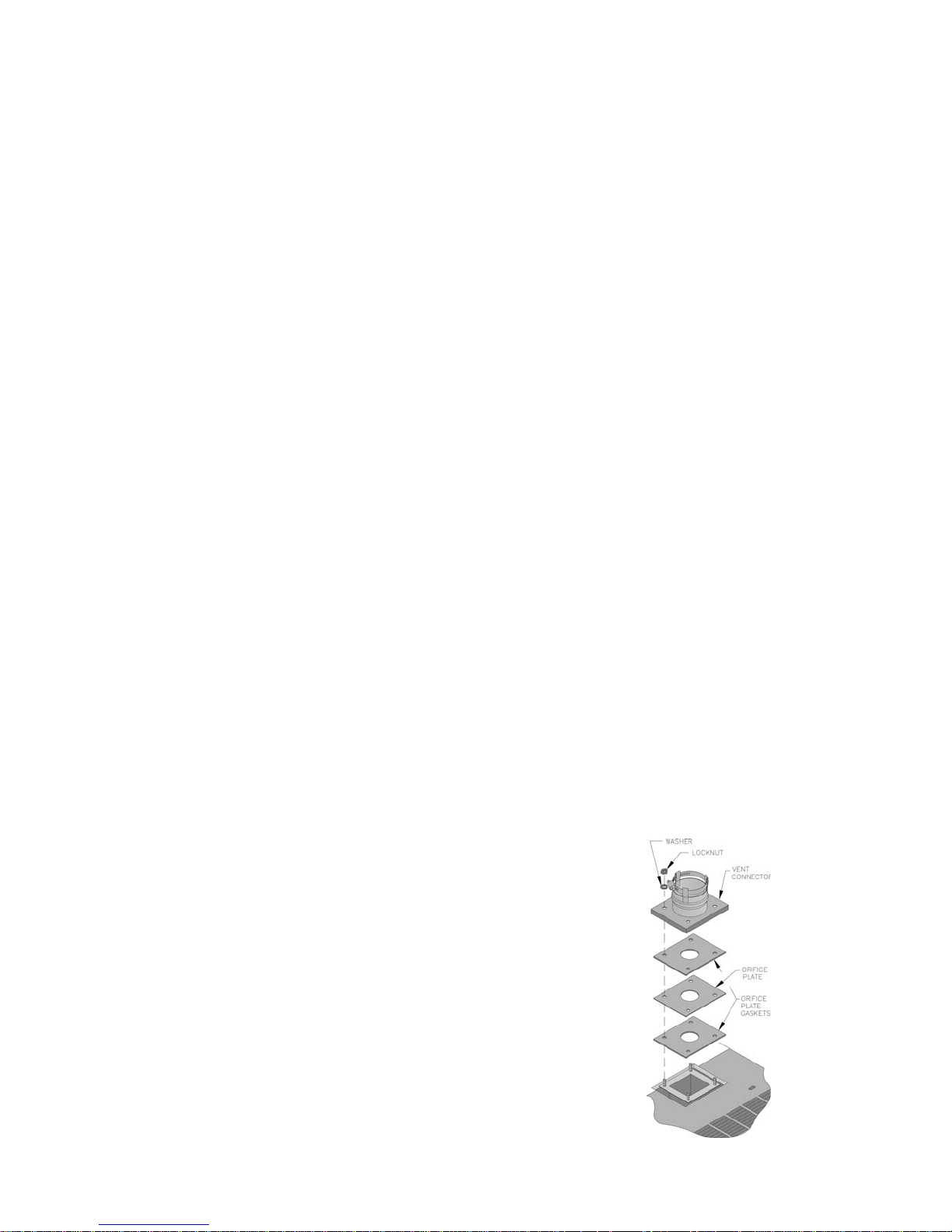
C. Install Vent Connector.
1. Remove vent connector from vent accessory carton.
2. Remove gaskets, orifi ce plate and hardware from
blower outlet fl ange.
3. Assemble orifi ce plate gaskets, orifi ce plate, and
vent connector. See Figure 7.
4. Secure vent connector with washers and locknuts.
Figure 7: Vent Connector Installation
11
Page 12

D. Install Vent Pipe, General.
1. Plan venting system to avoid possible contact with
plumbing or electrical wires. Start venting system at
vent connector and work toward the vent terminal.
2. Use non-combustible ¾ inch pipe strap to support
horizontal runs, maintain vent location and slope,
while preventing sags in pipe. Do not restrict
thermal expansion or movement of vent system.
Maximum support spacing is 5 feet. Do not
penetrate any part of the vent system with fasteners.
3. Provide and maintain vent pipe minimum clearance
to combustible materials. Vent pipe minimum
clearance to combustible material is fi ve (5) inches
when vent is installed in a fully enclosed (chase)
application or four (4) inches when vent is installed
with at least one side open, similar to a joist bay
application. Use thimble when penetrating
combustible wall.
a. 203PV and 204PV – Single wall thimble,
Burnham Part No. 8116116. Other wall thimble
manufac-turers are American Metal Products,
Hart & Cooley, and Metal Fab.
b. 205PV and 206PV – Double wall thimble,
Burnham Part No. 8116115 (accommodates 5
inch to 8-3/4 inch wall thickness). Another wall
thimble manufacturer is Hart & Cooley.
4. Once a vent pipe manufacturer and system is chosen
never mix and match vent systems.
5. If a non-standard length pipe is required:
Gasketed Vent System: The use of the adjustable length
pipe (P/N 8116319U) is recommended to complete a
non-standard pipe length. This pipe requires a
minimum installed length of 12¾ inch and can
adjust across a 7 inch gap up to a maximum of 19¾
inch long. (Note for the adjustable pipe the installed
length should be measured from the centerline of the
bead on the male end of the fi rst pipe to the end of
the female pipe excluding the locking band of the
second pipe with a single gasket.) Only in the event
the adjustable length pipe is not suffi cient a standard
length pipe may be cut using the procedure outlined
below for the Gasket-Less Vent System.
GNINRAW
.epiphtgnelelbatsujdarofsehcni¾91
.elbissopsiegakaelsageulffoksiR
Gasket-Less Vent System: Carefully cut pipe to length
using a hacksaw with minimum 32 teeth per inch or
circular saw with metal abrasive wheel. Remove
male (bead) end only – female (bell) end accepts
next fi tting or pipe.
ECITON
rodelifdnaepiphtiwerauqsebtsumtuC
ylluferaC.gniniojerofebhtoomsdednas
htiwdnahybepiptucfossendnuorerusne
VTRhtiwtniojlaeS.gnillatsnierofebsevolg
.launamsihtnideificeps
6. Seal all Burnham Gasket-Less vent, Burnham mixed
vent (Gasket-Less and Gasketed) and fi eld cut joints
using Dow Corning Silastic 732 RTV, Dow Corning
Silastic 736 RTV, GE RTV106, Polybac #500 RTV,
Sil-bond RTV 4500 (Acetoxy) and Sil-bond RTV
6500. Do not use other adhesives or sealants.
E. Install Vent Pipe, Burnham Gasket-Less Vent
System.
1. Procedure for Joining Burnham Gasket-Less Vent
Pipe and Fittings. See Figure 8A.
Figure 8A: Burnham Gasket-Less Vent Joint Detail
a. Clean joints of pipe or fi ttings using an alcohol
pad to remove any dirt and grease.
b. Slip a locking band over female (bell) end of
pipe/fi tting.
c. Apply a continuous 1/4 inch bead of sealant
around male end of joint no more than 1/8 inch
from end.
d. Align weld seams and use a slight twisting
motion to FULLY insert male end into female
end of joint. Ensure bead in male end rest against
the end of the female pipe.
e. Smooth sealant around joint for a continuous
fohtgneldellatsnimumixamdeecxereveN
seal. Reapply sealant if necessary.
f. Slip the locking band over joint and align closest
bead in locking band with bead in male end of
pipe.
g. Tighten locking band by HAND with a 5/16" nut
driver until snug plus ¼ turn. DO NOT
SECURE JOINTS WITH SHEET METAL
SCREWS OR POP RIVETS. DO NOT
PUNCTURE THE VENT SYSTEM!
12
Page 13

h. Once the installation is complete, operate
appliance and inspect all joints to ensure that fl ue
gases and/or liquid condensate will not escape.
F. Install Vent Pipe, Burnham Gasketed Vent System.
1. Procedure for Joining Burnham Gasketed Vent Pipe
and Fittings. See Figure 8B.
Figure 8B: Burnham Gasketed Vent Joint Detail
a. Wipe the male end of each joint using an alcohol
pad to remove any dirt and grease.
b. Align weld seams in pipes and use a slight
twisting motion to FULLY insert male end into
female end of joint. Ensure bead in male end of
pipe is below locking band and rest against the
end of the female pipe. Verify the factoryinstalled gasket is not dislodged or cut
c. Tighten locking band by HAND with a 5/16" nut
driver until snug plus ¼ turn. DO NOT
SECURE JOINTS WITH SHEET METAL
SCREWS OR POP RIVETS. DO NOT
PUNCTURE THE VENT SYSTEM!
d. Once the installation is complete, operate
appliance and inspect all joints to ensure that fl ue
gases and/or liquid condensate will not escape.
c. Align weld seams in pipes and use a slight
twisting motion to FULLY insert male end into
female end of joint. Ensure bead in male end of
pipe is below locking band and rest against the
end of the female pipe. Verify the factoryinstalled gasket is not dislodged or cut.
d. Smooth sealant around joint for a continuous
seal. Reapply sealant if necessary.
e. Tighten locking band by HAND with a 5/16" nut
driver until snug plus ¼ turn. DO NOT
SECURE JOINTS WITH SHEET METAL
SCREWS OR POP RIVETS. DO NOT
PUNCTURE THE VENT SYSTEM!
f. Once the installation is complete, operate
appliance and inspect all joints to ensure that fl ue
gases and/or liquid condensate will not escape.
2. Procedure for joining the female end of Burnham
Gasket-Less Vent with the male end of Burnham
Gasketed Vent. See Figure 8D.
G. Install Vent Pipe, Burnham Gasket-Less & Gasketed
Vent System.
1. Procedure for joining the male end of Burnham
Gasket-Less Vent with the female end of Burnham
Gasketed Vent. See Figure 8C.
Figure 8C: Burnham Gasket-Less Male and
Gasketed Female Vent Joint Detail
a. Clean the male end of each joint using an alcohol
pad to remove any dirt and grease.
b. Apply a continuous ¼ inch bead of sealant
around male end of joint no more than 1/8 inch
from end.
Figure 8D: Burnham Gasket-Less Female and
Gasketed Male Vent Joint Detail
a. Clean joints of pipe or fi ttings using an alcohol
pad to remove any dirt and grease.
b. Slip a locking band over female (bell) end of
pipe/fi tting.
c. Apply a continuous ¼ inch bead of sealant
around male end of joint no more than 1/8 inch
from end.
d. Align weld seams in pipes and use a slight
twisting motion to FULLY insert male end into
female end of joint.
e. Smooth sealant around joint for a continuous
seal. Reapply sealant if necessary.
f. Slip the locking band over joint and align closest
bead in locking band with bead in male end of
pipe.
g. Tighten locking band by HAND with a 5/16" nut
driver until snug plus ¼ turn. DO NOT
SECURE JOINTS WITH SHEET METAL
SCREWS OR POP RIVETS. DO NOT
PUNCTURE THE VENT SYSTEM!
13
Page 14

h. Once the installation is complete, operate
appliance and inspect all joints to ensure that fl ue
gases and/or liquid condensate will not escape.
H. Horizontal (Through Wall) V ent Installation.
1. Maintain minimum ¼ inch per foot slope in
horizontal runs. Slope pipe down toward vent
terminal. Position weld seams in vent pipes in all
horizontal runs at the top to avoid condensate from
lying on the seams.
2. Vent terminal location restricted per following:
a. Minimum 12 inches above grade plus normally
expected snow accumulation level, or 7 feet
above grade if located adjacent to public
walkway. Do not install over public walkway
where local experience indicates condensate or
vapor from Category III appliances creates a
nuisance or hazard.
b. Minimum 3 feet above any forced air inlet
located within 10 feet.
c. Minimum 4 foot below, 4 foot horizontally from,
or 1 foot above any door, window, or gravity air
inlet.
d. Minimum 4 feet (6 feet in Canada) horizontally
from, and in no case above or below, unless a
4-foot horizontal distance is maintained, from
electric meters, gas meters, regulators and relief
equipment.
e. Minimum 12 inches from overhang or corner.
3. Use wall thimble when passing through combustible
outside wall (thimble use optional for
noncombustible wall). Insert thimble through wall
from outside. Secure outside fl ange to wall with
nails or screws, and seal with adhesive material.
Install inside fl ange to inside wall, secure with nails
or screws, and seal with adhesive material.
4. For noncombustible wall when thimble is not used
size opening such that female (bell) end with
locking band attached cannot pass through.
5. Join vent terminal to vent pipe. Locate vent
terminal 3 inches (minimum) and 6 inches
(recommended) from wall when joined to inside
vent piping. See Figure 9. Vent terminal clearance
to vinyl wall surfaces is 6 inches.
6. Insert vent pipe through thimble/opening from
outside and join to vent system. Apply sealant
between vent pipe and opening/thimble to provide
weathertight seal.
Figure 9: Recommendations for Thimble and Wall Penetration
14
Page 15

VI. Electrical
A. General. Install wiring and ground boiler in accordance
with requirements of authority having jurisdiction, or in
absence of such requirements the National Electrical
Code, ANSI/NFPA 70, and/or the CSA C22.1 Electric
Code.
B. Install thermostat. Locate on inside wall
approximately 4 feet above fl oor. Do not install on
outside wall, near fi replace, or where infl uenced by
drafts or restricted air fl ow, hot or cold water pipes,
lighting fi xtures, television, or sunlight. Allow free air
movement by avoiding placement of furniture near
thermostat.
C. Wire thermostat. Provide Class II circuit between
thermostat and boiler. Run wires through grommet in
Jacket Left Side Panel. Set thermostat heat anticipator
to 0.6 amps. See Figure 10.
D. Wire boiler. Boiler is rated for 120 VAC, 60 hertz, less
than 12 amperes. A separate electrical circuit must be
run from the main electrical service with an overcurrent device/disconnect in the circuit. A service
switch is recommended and may be required by some
local jurisdictions. Connect to black and white wires
and green ground screw. See Figure 10.
E. Alliance water heater (if used). See Figure 10. Also
refer to Alliance Installation, Operating and Service
Instructions.
F. For installations using zone valves provide separate
transformer for zone valve wiring. Consult zone valve
manufacturer for assistance.
Figure 10: Wiring Diagram
15
Page 16

VII. System Start-up
A. Safe operation and other performance criteria were
met with gas manifold and control assembly provided
on boiler when boiler underwent tests specifi ed in
American National Standard for Gas-Fired LowPressure Steam and Hot Water Boilers, ANSI Z21.13.
B. Fill heating system with water and vent air from
system. Use the following procedure on a Series Loop
System equipped with zone valves. See Figure 3.
1. Close isolation valve in boiler supply piping.
2. Isolate all circuits by closing zone valves or
balancing valves.
3. Attach hose to hose bib located just below isolation
valve in boiler supply piping. Terminate hose in fi ve
gallon bucket at a suitable fl oor drain or outdoor
area).
4. Starting with one circuit, open zone valve.
5. Open hose bib.
6. Open fi ll valve. Makeup water line should be
located directly above isolation valve in boiler
supply piping.
7. Allow water to overfl ow from bucket until discharge
from hose is bubble free for 30 seconds.
8. Open zone valve to second zone to be purged, then
close fi rst. Repeat this step until all zones have been
purged, but always have one zone open. At
completion, open all zone valves.
9. Close hose bib, continue fi lling system until pressure
gauge reads 12 psi. Close fi ll valve.
Note: If makeup water line is equipped with
pressure reducing valve, system will automatically
fi ll to 12 psi. Leave globe valve open.
10. Open isolation valve in boiler supply piping.
11. Remove hose from hose bib.
D. Prepare to check operation.
1. Obtain gas heating value (in Btu per cubic foot)
from gas supplier.
2. Connect manometer to pressure tap on gas valve.
See Figure 12.
Figure 12: Gas Valve Pressure Tap
3. For natural gas fi red boiler, temporarily turn off all
other gas-fi red appliances.
E. Follow Operating Instructions to place boiler in
operation. See Figure 17.
F. Sequence of Operation. See Figure 14. If boiler fails
to operate properly, see Troubleshooting Tree on pages
20-22.
G. Check gas piping and connections between Gas Valve
and Manifold, Orifi ces and Pilot Tubing. Use soap
solution or other approved method. See Figure 13.
C. Check main burners. See Figure 11. Rear of burner
must be in vertical slot in rear of burner tray. Front of
burner must be seated on orifi ce.
16
Figure 13: Schematic Pilot and Gas PipingFigure 11: Main Burner Installation
Page 17

H. Check pilot burner fl ame. See Figure 15. Flame
should be steady, medium hard blue enveloping 3/8 to
½ inch of sensing probe.
Figure 15: Pilot Burner Flame
I. Check main burner fl ame. See Figure 16. Flame
should have clearly defi ned inner cone with no yellow
tipping. Orange-yellow streaks should not be confused
with true yellow tipping.
Figure 14: Sequence of Operation
Figure 16: Main Burner Flame
J. Check thermostat operation. Raise and lower
temperature setting to start and stop boiler operation.
K. Check ignition control module shut-off. Disconnect
igniter/sensor cable from Terminal 9 (SPARK). Gas
valve should close and pilot and main burners should
extinguish.
17
Page 18

L.
Check low water cut-off (if used). Drain boiler water
below LWCO set point. Burners should extinguish.
M. Check limit.
1. Adjust thermostat to highest setting.
2. Observe temperature gauge. When temperature is
indicated, adjust limit to setting below observed
temperature. Main burners and pilot burner should
extinguish and blower stop.
3. Adjust limit to setting above observed temperature.
Ignition sequence should begin.
4. Adjust thermostat to lowest setting. Adjust limit to
desired setting.
N. Adjust gas input rate to boiler (Natural Gas).
1. Adjust thermostat to highest setting.
2. Check manifold gas pressure. Manifold pressure is
listed on rating label. Adjust gas valve pressure
regulator as necessary (turn adjustment screw
counterclockwise to decrease manifold pressure, or
clockwise to increase manifold pressure). If pressure
can not be attained, check gas valve inlet pressure. If
less than minimum gas supply pressure listed on
rating label, contact gas supplier for assistance.
3. Clock gas meter for at least 30 seconds. Use Table 6
to determine gas fl ow rate in Cubic Feet per Hour.
4. Determine Input Rate. Multiply gas fl ow rate by gas
heating value.
Table 6: Gas Flow Rate in Cubic Feet per Hour
sdnoceS
enOrof
noituloveR
0306021042
2365311522
4335601212
6305001002
837459981
045409081
243468271
441428461
649387751
847357051
056327441
255396831
453376331
652346921
851326421
060306021
flaH-enO
.tF.uC
enO
.tF.uC
laiDreteMsaGfoeziS
5. Compare measured input rate to input rate listed on
rating label.
a. Boiler must not be overfi red. Reduce input rate
by decreasing manifold pressure. Do not reduce
more than 0.3 inch w.c. If boiler is still overfi red,
contact your Burnham distributor or Regional
Offi ce for replacement Gas Orifi ce.
b. Increase input rate if less than 98% of rating
label input. Increase manifold gas pressure no
more than 0.3 inch w.c. If measured input rate is
still less than 98% of rated input:
i. Remove Main Burners per procedure in
Section VIII: Service.
ii. Remove gas orifi ces. Drill one (1) drill size
larger (drill size is stamped on orifi ce, or see
Key No. 4D).
iii. Reinstall gas orifi ces and main burners.
Measure input rate.
6. Recheck Main Burner Flame.
7. Adjust thermostat to normal setting.
8. Return other gas-fi red appliances to previous
conditions of use.
O. Adjust gas input rate to boiler (LP/Propane).
1. Adjust thermostat to highest setting.
2. Check manifold pressure. Adjust gas valve pressure
regulator to obtain 10 inches w.c. manifold pressure.
Adjust gas valve pressure regulator as necessary
(turn adjustment screw counterclockwise to decrease
manifold pressure, or clockwise to increase
manifold pressure). If pressure can not be attained,
check gas valve inlet pressure. If less than minimum
owT
.tF.uC
gas supply pressure listed on rating label, contact
gas supplier for assistance.
3. Recheck Main Burner Flame
4. Adjust thermostat to normal setting.
P. COMBUSTION CHAMBER BURN-OFF
1. The mineral wool combustion chamber panels
contain a cornstarch based binder that must be
burned out at installation to prevent odors during
subsequent boiler operation.
2. Ventilate the boiler room, set the high limit to its
maximum setting, set the thermostat to call for heat.
Allow the boiler to fi re for at least an hour or until
the odor from the cornstarch has dissipated.
3. Return the high limit and thermostat to their desired
settings.
Q. Review User's Information Manual and system
operation with owner or operator.
R. Post instructions near boiler for reference by owner
and service personnel. Maintain instructions in legible
condition.
18
Page 19

Figure 17: Operating Instructions
19
Page 20

20
Page 21

21
Page 22

22
Page 23

noitamrofnIytefaStcudorPtnatropmI
tcudorPrebiFcimareCyrotcarfeR
Warning:
This product contains refractory ceramic fi bers (RCF). RCF has been classifi ed
as a possible human carcinogen. After this product is fi red, RCF may, when
exposed to extremely high temperature (>1800F), change into a known human
carcinogen. When disturbed as a result of servicing or repair, RCF becomes
airborne and, if inhaled, may be hazardous to your health.
AVOID Breathing Fiber Particulates and Dust
Precautionary Measures:
Do not remove or replace previously fi red RCF (combustion chamber
insulation, target walls, canopy gasket, fl ue cover gasket, etc.) or attempt any
service or repair work involving RCF without wearing the following protective
gear:
1. A National Institute for Occupational Safety and Health (NIOSH)
approved respirator
2. Long sleeved, loose fi tting clothing
3. Gloves
4. Eye Protection
• Take steps to assure adequate ventilation.
• Wash all exposed body areas gently with soap and water after contact.
• Wash work clothes separately from other laundry and rinse washing
machine after use to avoid contaminating other clothes.
• Discard used RCF components by sealing in an air tight plastic bag.
First Aid Procedures:
• If contact with eyes: Flush with water for at least 15 minutes. Seek
immediate medical attention if irritation persists.
• If contact with skin: Wash affected area gently with soap and water.
Seek immediate medical attention if irritation persists.
• If breathing diffi culty develops: Leave the area and move to a
location with clean fresh air. Seek immediate medical attention if
breathing diffi culties persist.
• Ingestion: Do not induce vomiting. Drink plenty of water. Seek
immediate medical attention.
23
Page 24

VIII. Service
A. General. Inspection and service should be conducted
annually. Turn off electrical power and gas supply while
conducting service or maintenance. Follow instructions
TO TURN OFF GAS TO APPLIANCE. See Figure 17.
NOITUAC
nehwnoitcennocsidotroirpseriwllalebaL
esuacnacsrorregniriW.slortnocgnicivres
nareporpmi
.gnicivresretfanoitareporeporp
B. Inspect Housekeeping. Boiler area must be clear and
free from combustible materials, gasoline and other
fl ammable vapors and liquids. Remove obstructions to
the fl ow of combustion and ventilation air.
C. Service Low water cut-off (if so equipped). Follow
instructions provided with low water cut-off
D. Inspect Vent System for obstructions in vent pipe, soot
accumulation, deterioration of pipe or joints, and proper
support:
1. Remove vent connector and vent pipe. See Figure
19.
2. Remove all obstructions. Check and clean vent
terminal screens.
3. Remove soot accumulations with wire brush and
vacuum.
4. Replace deteriorated parts.
5. Repair deteriorated joints. See Section V: Venting.
E. Inspect Boiler Flue Passages for blockage or soot
accumulation. See Figure 19.
1. Disconnect vent connector from blower discharge
fl ange.
2. Remove sheet metal screws securing Jacket Top
Panel. Lift panel and rotate about relief valve piping
until top of boiler is exposed. If piping or wall
prevent full rotation of top panel for access to
canopy, cut slot into relief valve opening and
remove top panel.
3. Disconnect blower connection from wiring harness
in vestibule.
4. Remove bolts securing canopy to boiler sections.
Cut silastic sealant around base of canopy, pry
canopy from boiler sections and remove canopy/
blower assembly from boiler.
5. Using fl ashlight, examine all fl ue passageways.
a. If passageways are free of soot and obstruction,
replace canopy, secure and seal using kit
available from Burnham Distributors, Part No.
6111716.
yfireV.noitareposuoregnadd
b. If passageways need cleaning, remove burners as
described in Paragraph F below. Using long
handle wire or bristle fl ue brush and vacuum,
brush fl ueways thoroughly from top of boiler as
illustrated in Figure 19. Replace canopy and seal
using kit available from Burnham Distributors,
Part No. 6111716.
GNINRAW
237-VTRhtiwdelaeserebtsumyponaC
tnettimretnIF°005(tnalaeSrebbuRenociliS
.)ytuD
6. Reinstall jacket top panel, vent pipe and vent
connector in reverse manner. Reconnect electrical
connector to blower.
F. Clean Main Burners and Firebox.
1. To remove burners for cleaning, changing orifi ce
plugs, or repairs:
a. Remove jacket Front Panel.
b. Disconnect pilot tubing at gas valve.
c. Disconnect igniter/sensor cable and ground wire
at Ignition Module.
d. Disconnect Flame Rollout Switch wires.
e. Remove Burner Access Panel.
f. Mark Pilot Main Burner location on Manifold.
g. Hold burner on throat. Lift slightly to clear
orifi ce. Pull burner from combustion chamber.
See Figure 11. Pilot Main Burner can only be
removed by lifting at 45° angle after adjacent
burner to right is removed.
2. Brush top of burners with a soft bristle brush. See
Figure 19. Vacuum burners.
3. Check orifi ces. Drilled passageways must be free of
lint or dirt.
4. Vacuum tip of Pilot Burner.
5. Clean fi rebox by vacuuming. Exercise care not to
disturb insulation inside base.
6. Install burners by reversing procedure used to
remove burners. Burner with pilot assembly must be
in same location as original installation. See Table 7.
Burners must be properly located on support bracket
at rear of burner. See Figure 11. Slide burner over
orifi ce.
7. Reconnect pilot gas supply, igniter/sensor cable, and
ground wire. Reinstall Burner Access Panel.
Reconnect Flame Rollout Switch wires.
G. Check operation. Follow Paragraphs D through O
from Section VII: System Start-up.
24
Page 25

Table 7: Pilot Burner Location
relioB
ledoM
VP3021 2&1
VP4022 3&2
VP5023 4&3
VP6024 5&4
.reliobfotnorf
htiwrenruBniaM
*tekcarBtoliP°06
H. Removal or replacement of pilot assembly or
pilot assembly parts. If pilot assembly, sensor or
pilot orifi ce need replacing, remove main burner
with pilot using procedure described in
Paragraph F.1.
1. To replace orifi ce.
a. Disconnect pilot tubing. Pilot orifi ces
screw into Pilot Burner. Replace with
Honeywell 388146NE (Natural Gas) or
Honeywell 388146KP (LP/Propane).
b. Reconnect pilot tubing and check for
leaks.
2. To adjust or check spark gap between
electrode and hood on Honeywell Q348A
intermittent pilot. See Figure 18.
a. Use round wire gauge to check spark
gap.
b. Spark gap should be 1/8 inch for
optimum performance.
3. To replace complete pilot assembly.
a. Remove two machine screws holding
pilot burner to pilot bracket.
b. Disconnect pilot tubing.
c. Disconnect all other leads to pilot.
d. Select pilot assembly with identical
model number, reconnect leads and pilot
tubing. Resecure to pilot bracket.
4. Reinstall main burner following procedure
described in Paragraph F.
detacoLrenruBtoliP
niaMneewteB
*srenruB
morfdeweivsathgirottfelderebmunsrenrubniaM*
Figure 18: Spark Gap Setting
I. Lubrication. There are no parts requiring
lubrication by service technician or owner.
Circulator bearings are water lubricated. Blower
motor bearings are factory sealed.
J. Procedure for measuring blower inlet
pressure. See Figure 20.
1. With boiler off, remove hose at pressure
switch.
2. With tee connect water manometer as shown
with additional tubing.
Figure 19: Flueway Cleaning
25
Page 26

Table 8: Minimum Fan Pressure
ledoMrelioB
VP302.c.wsehcni04.0-
VP402.c.wsehcni04.0-
VP502.c.wsehcni07.0-
VP602.c.wsehcni07.0-
3. Start boiler and read pressure on manometer when
boiler water temperature reaches operating
temperature. Refer to Table 8 for minimum
readings.
NOTE: If switch drops-out before boiler reaches
temperature or if pressure reading is below
minimum shown in Table 8, check for cracks in hose
or contact your nearest Burnham representative.
4. Stop boiler, remove manometer and reconnect hose
to pressure switch.
rewolBmuminiM
erusserPtelnI
IX. Repair Parts
Figure 20: Procedure for Measuring Fan Pressure
All Series 2PV Repair Parts may be obtained through your local Burnham Wholesale distributor. Should you require
assistance in locating a Burnham distributor in your area, or have questions regarding the availability of Burnham
products or repair parts, please contact Burnham Customer Service at (717) 481-8400 or Fax (717) 481-8408.
26
Page 27

yeK
.oN
noitpircseD
VP302VP402VP502VP602
rebmuNtraP]ytitnauQ[
ylbmessAnoitceS.1
ylbmessArewolB/yponaC.2
A2yponaC
B2"1x02-¼,tloBegairraC erawdraHnommoC]2[
C2EAS,¼,rehsaW erawdraHnommoC]01[
D2xeHyvaeH
E2]F2.oNyeKnidedulcnI[teksaGgnitnuoMrewolB 8406028]1[9406028]1[
F2rewolB 4171116]
G2]F2.oNyeKnidedulcnI)2([teksaGetalPecifirO 2406028]2[5306028]2[
H2etalPecifirO
J2803AreywD,gnittiFerusserP 756228]1[
K2]F2.oNyeKnidedulcnI)4([ssarB,02-4/1,t
L202-¼,tunkcoLxeH erawdraHnommoC]4[
,02-¼,tuN erawdraHnommoC]2[
uNxeH 42406808]4[
123071716124071716125071716126071716
]1[
43071116
1[5171116]1[
]1[
53071117
]1[
6
4407111
]1[
54
071117
]1[
45071116
]1[
55071117
]1[
46071116
]1[
56071117
27
Page 28

yeK
.oN
noitpircseD
VP302VP402VP502VP602
rebmuNtraP]ytitnauQ[
puorGylbmessAesaB.3
3etelpmoC,ylbmessAesaB193006816]1[194006816]1[195006816]1[196006816]1[
A3ylbmessAyarTesaB193006817]1[194006817
B3repparWesaB113006817]1[114006817]1[115006817]1[116006817]1[
1B3noitalusnIdnEesaB 1
2B3noitalusnIraeResaB53006027]1[54006027]1[55006027]1[56006027]1[
C3ylbmessAlenaPtnorFesaB143006816]1
D3yarTrenruB503006817]1[504006817]1[505006817]1[506006817]1[
E3ylbmessAgeL
1E3geLesaB 12006817]4[
2E3edilGnolyN 6006818
F3lenaPsseccArenruB163006817]1[164006817]1[165006817
G3tfeL,tekcarBtnemhcattAtekcaJ 11006407]1[
H3thgiR,tekcarBtnemhcattAtekcaJ 21006407]1[
J3
K3
L3"¼1x81-"61/5,gnippaTfleS,wercS 71706808]4[
M3"61/5,rehsaWtalF erawdraHnommoC]4[
esaB 1006816]4[
½,teksaGtlefareC
"2x"
004-FRCellivsnaM-snhoJ
aeH
detalP,"½x02-¼,d
[144006816]1[145006816]1[146006816]1[
naPspillihP,FepyTgnippaT-fleS,wercS
]1[195006817]1[196006817]1[
06027]2[
]1[166006817]1[
2006026]1[
00706808]02[
N381-"61/5,
P3"½x8#,daeHspillihP,lateMteehS,wercS erawdraHnommoC]2[
tuNkcoLxeH 46406808]4[
28
Page 29

rebmuNtraP]ytitnauQ[
.oNyeKnoitpircseD
VP302VP402VP502VP602
srenruBniaMdnadlofinaM.4
A4renruBniaM9906328]2[9906328]4[9906328]6[9906328]8[
B4tekcarBtoliP°06htiwrenruBniaM 8906328]1[
C4dlofinaM330062
larutaN(D4
)ylnOsaG
D4
enaporP/PL(
)ylnO
E4"61/3x23-01#,enihcaM,wercS 00806808]2[
F4
28]1[34006228]1[35006228]1[36006228]1[
kniP,54#,ecifirOrenruBniaM
neerG,55#,ecifirOrenruBniaM807228]3[---------------
.1,ecifirOrenruBniaM-----507228]5[507228]7[507228]9[
TgnippaT-fleS,wercS
elpruP,mm52
spillihP,Fepy
detalP,"2/1x02-4/1,daeHnaP
117228]3[
117228]5[117228]7[117228]9[
00706808]4[
29
Page 30

yeK
.oN
noitpircseD
VP302VP402VP502VP602
rebmuNtraP]ytitnauQ[
evlaVsaGdnarenruBtoliP.5
A5
B5
liP
C5TPN¼xDO"8/1,gnittiF/tuNnoisserpmoC E5dnaA5.oNyeKhtiwdedulcnI
D5"03xDO"8/1,gnibuTtoliP 0116328]1[
E5
F563-008493llewyenoH,"63,elbaCrosneS/retingI 4806328]1[
G5ylbmessAeriWdnuorG 4506316]1[
30
3331A843QllewyenoH,saGlarutaN,ylbmessAtoliP 4016328]1[
1431A843QllewyenoH,saGPL,ylbmessAtoliP 7016328]
EN641883llewyenoHsaGlarutaN,ecifirOtoliP
PK641883llewyenoHenaporP/PL,ecifirOto
000
6C4028RVllewyenoH,saGlarutaN,½x½,evlaVsaG 67106618]1[
8106C4028RVllewyenoH,enaporP/PL,½x½,evlaVsaG 08106
1[
A5.oNyeKhtiwdedulcnI
618]1[
Page 31

yeK
.oN
noitpircseD
VP302VP402VP502VP602
rebmuNtraP]ytitnauQ[
tekcaJ.6
A6)1(lenaPdnuoR-A-parWtekcaJ713071406]1[714071406]1[715071406]1[716071406]1[
B6)1(lenaPelubitseVreppUtekcaJ12
C6lenaPelubitseVrewoLtekcaJ2223071406]1[2224071406]1[22250
D6)2()1(lenaPpoTtekcaJ433071406]1[434071406]1[435071406]1[436071406]1[
E6rooDelbavomeRtn
F6lenaPtnorFrewoLtekcaJ313071406]1[314071406]1[31507
G6"½x8#,lateMteehS,wercS erawdraHnommoC]02[
H651-3901-BSocyeH,gnihsuBpanS 7526318]2[
J662-
K65-734-BSocyeH,gnihsuBpanS 8406318]1[
L6etalPogoLmahnruB 70106418]1[
orFtekcaJ443071406]1[444071406]1[445071406]1[446071406]1[
ofilaCnidellatsnisreliobroF)2(
23071406]1[1224071406]1[1225071406]1[1226071406]1[
0002-BSocyeH,gnihsuBpanS 6626318]1[
iredronehw'adanaCroF'etacidni,adanaCnidellatsnisreliobroF)1(
71406]1[2226071406]1[
1406]1[316071406]1[
.gn
.gniredronehw'ainrofilaCroF'etacidni,ainr
31
Page 32

32
Page 33

yeK
.oN
noitpircseD
VP302VP402VP502VP602
rebmuNtraP]ytitnauQ[
slortnoCdnamirTsuoenallecsiM.7
A7
B74321D0804LllewyenoH,timiL 10-981001]1[
1B7TPN½,lleWnoisremmI B7htiwdedulcnI
2B7
3B7)ylnOtimiLlauD(2121B0804LllewyenoHtimiL 47406108]1[
C71005D5828RllewyenoH,yaleR/remrofsnarT U55106108]1[
1C76001U2228RllewyenoH,TSPD,yaleR U69006108]1[
2C7"½1x"4x"4,xoBnoitcnuJ 9526318]1[
D7hctiwStuolloRemalF 44006108]1[
1D7tekcarBhctiwStuolloRemalF 8106817]1[
E7hctiwSerusserP 67806106]1[77806106]1[
1E7
)ylnOtimiL
50-804-01ocarbnoC
1/3,gnibuTenociliS
/3,gnibuTenociliS
"¼51x"8/1,gnibuTenociliS
,TPN¾,isp03,evlaVfeileRytefaS
lauD(A078321llewyenoH,TPN¾,lleWnoisremmI
)VP402/302(gnoL"21x.D.I"6
)VP502(gnoL"31x.D.I"61/3,gnibuTenociliS
)VP602(gnoL"51x.D.I"61
91306618]1[
62406108]1[
)htgneLyficepS(7006109
F77001E0768SllewyenoH,eludoMnoitingI 80106108]1[
G7eguaGerusserP
H7
1H7
aG 600206608]2[
J7TPN¼1,egnalF 310206608]2[
1J7"½1x41-61/7,daeHxeHpaC,wercS erawdraHnommoC]4[
2J741-61/7,xeH,tuN erawdraHnommoC]4[
K730-203-53ocarbnoC,TPN¾,evlaVniarD 160306608]1[
-erutarepmeT U4616508]1[
22-RFNttessoG&lleB,steksaGhtiwrotalucriC 4716508]1[
iwrotalucriC 3716508]1[
F700ocaT,steksaGhtiwrotalucriC 0716508]1[
0100ocaT,steksaGhtiwrotalucriC 6716508]1
971015sofdnurG,teksaG 610206608]2[
seireS'00'ocaT,teks
F24-51PUsofdnurG,steksaGht
)03-CLS(22-RFNttessoG&lleB,teksaG 920206608]2[
[
33
Page 34

yeK
.oN
noitpircseD
VP302VP402VP502VP602
rebmuNtraP]ytitnauQ[
notraCyrosseccAtneVdeteksaG.8
A8rotcennoCtneV6036118]1[7036118]1[
B8lanimreTtneV 0171118]1[
323071116325071116
34
Page 35

X. Low Water Cut Off (LWCO) on Hot Water Boilers
GNINRAW
.)OCWL(ffOtuCretaWwoLtekramretfanallatsniotseriwyrotcaftucotTPMETTATONOD
.ffOtuCretaWwoLrofdeifitnediyllacificepssnoitcennocesuylnO
.snoitcurtsnis'rerutcafunam)OCWL(ffOtuCretaWwoLehtwollof,sesacllanI
When
A low water cutoff is required to protect a hot water
boiler when any connected heat distributor (radiation) is
installed below the top of the hot water boiler (i.e.
baseboard on the same fl oor level as the boiler). In
addition, some jurisdictions require the use of a LWCO
with a hot water boiler.
Where
The universal location for a LWCO on both gas and oil
hot water boilers is above the boiler, in either the supply
or return piping. The minimum safe water level of a
water boiler is at the uppermost top of the boiler; that is,
it must be full of water to operate safely.
What Kind
Typically, in residential applications, a probe type
LWCO is used instead of a fl oat type, due to their
relative costs and the simplicity of piping for a probe
LWCO.
How to Pipe
A “tee” is commonly used to connect the probe LWCO
to the supply or return piping, as shown below.
draining the heating system. Many probe LWCO
manufacturers recommend an annual inspection of the
probe.
How to Wire
LWCO’s are available in either 120 VAC or 24 VAC
confi gurations. The 120 VAC confi guration can be
universally applied to both gas and oil boilers by wiring
it in the line voltage service to the boiler (after the
service switch, if so equipped).
The presence of water in a properly installed LWCO
will cause the normally open contact of the LWCO to
close, thus providing continuity of the 120 VAC service
to the boiler.
It is recommended to supply power to the probe LWCO
with the same line voltage boiler service as shown
below.
LWCO Location
Select the appropriate size tee using the LWCO
manufacturer’s instructions. Often, the branch
connection must have a minimum diameter to
prevent bridging between the probe and the tee. Also,
the run of the tee must have a minimum diameter to
prevent the end of the probe from touching or being
located too close to the inside wall of the run of the tee.
Ideally, manual shutoff valves should be located above
the LWCO and the boiler to allow for servicing. This
will allow probe removal for inspection without
Wiring of Typical LWCO
A 24 VAC LWCO is used primarily for gas fi red boilers
where a 24 volt control circuit exists within the boiler.
However, a 24 VAC LWCO can only be used if the
boiler manufacturer has provided piping and wiring
connections and instructions to allow for this
application.
How to Test
Shut off fuel supply. Lower water level until water
level is BELOW the LWCO. Generate a boiler demand
by turning up thermostat. Boiler should not attempt to
operate. Increase the water level by fi lling the system.
The boiler should attempt to operate once the water
level is above the LWCO.
35
Page 36

Limited Warranty
FOR RESIDENTIAL CAST IRON WATER BOILERS
Subject to the terms and conditions set forth below, U.S. Boiler™
Co., Inc. Lancaster, Pennsylvania hereby extends the following limited
warranties to the original owner of a residential grade water boiler
manufactured and shipped on or after July 1,1991:
ONE YEAR LIMITED WARRANTY
ON RESIDENTIAL GRADE WATER BOILERS
U.S. Boiler Co., Inc. warrants to the original owner that its residential
grade water boilers comply at the time of manufacture with recognized
hydronic industry standards and requirements then in effect and will be
free of defects in material and workmanship under normal usage for a
period of one year from the date of original installation. If any part of a
water boiler is found to be defective in material or workmanship during
this one year period, U.S. Boiler Co., Inc. will, at its option, repair or
replace the defective part.
LIFETIME LIMITED WARRANTY ON HEAT EXCHANGER
U.S. Boiler Co., Inc. warrants to the original owner that the heat
exchanger of its residential grade water boilers will remain free from
defects in material and workmanship under normal usage for the
lifetime of the original owner at the original place of installation. If a
claim is made under this warranty during the fi rst ten years from the
date of original installation, U.S. Boiler Co., Inc. will, at its option, repair
or replace the heat exchanger. If a claim is made under this warranty
after the expiration of ten years from the date of original installation,
U.S. Boiler Co., Inc. will, at its option and upon payment of the pro-rated
service charge set forth below, repair or replace the heat exchanger.
The service charge applicable to a heat exchanger warranty claim is
based upon the number of years the heat exchanger has been in service
and will be determined as a percentage of the retail price of the heat
exchanger model involved at the time the warranty claim is made as
follows:
sraeY
ecivreSnI
egrahCecivreS
fo%sa
ecirPliateR
sraeY
ecivreSnI
egrahCecivreS
fo%sa
ecirPliateR
NOTE: If the heat exchanger model involved is no longer available due to
product obsolescence or redesign, the value used to establish the retail
price will be the published price as shown in the Burnham Hydronics
Repair Parts Price Sheet where the heat exchanger last appeared or the
current retail price of the then nearest equivalent heat exchanger.
ADDITIONAL TERMS AND CONDITIONS
1. Applicability: The limited warranties set forth above are extended
only to the original owner at the original place of installation within the
United States and Canada. These warranties are applicable only to
water boilers designated as residential grade by U.S. Boiler Co., Inc. and
installed in a single or two-family residence and do not apply to steam
boilers of any kind or to commercial grade boilers.
2. Components Manufactured by Others: Upon expiration of the
one year limited warranty on residential grade water boilers, all boiler
components manufactured by others but furnished by U.S. Boiler Co.,
Inc. (such as oil burner, circulator and controls) will be subject only to the
manufacturer’s warranty, if any.
3. Proper Installation: The warranties extended by U.S. Boiler Co., Inc.
are conditioned upon the installation of the residential grade water boiler
in strict compliance with U.S. Boiler Co., Inc. installation instructions. U.
S. Boiler Co., Inc. specifi cally disclaims liability of any kind caused by or
relating to improper installation.
4. Proper Use and Maintenance: The warranties extended by U.S. Boiler
Co., Inc. conditioned upon the use of the residential grade water boiler
01-111213141516171
oN
5015102520353
egrahC
81910212223242
0454055506560757
for its intended purposes and its maintenance accordance with U. S.
Boiler Co., Inc. recommendations and hydronics industry standards.
These warranties will be inapplicable if the residential grade water boiler
is used or operated over its rated capacity, is subjected to unauthorized
modifi cation, or is damaged as a result of being otherwise improperly
operated or serviced including, but not limited to, damage from any of the
following: operation with insuffi cient water, allowing the boiler to freeze,
subjecting the boiler to fl ood conditions, and operation with unapproved
water or fuel additives which cause deposits or corrosion.
5. Removal and Installation: These warranties do not cover expenses
of removal or reinstallation. The owner is responsible for the cost of
removing and reinstalling any defective part and its replacements and all
labor and material connected therewith.
6. Exclusive Remedy: U.S. Boiler Co., Inc. obligation for any breach
of these warranties is limited to the repair or replacement of its parts in
accordance with the terms and conditions of these warranties.
7. Limitation of Damages: Under no circumstances shall U.S. Boiler Co.,
Inc. be liable for incidental, indirect, special or consequential damages
of any kind whatsoever under these warranties, including, but not limited
to, injury or damage to persons or property and damages for loss of use,
inconvenience or loss of time. U.S. Boiler Co., Inc. liability under these
warranties shall under no circumstances exceed the purchase price paid
by the owner for the residential grade water boiler involved. Some states
do not allow the exclusion or limitation of incidental or consequential
damages, so the above limitation or exclusion may not apply to you.
8. Limitation of Warranties: These warranties set forth the entire
obligation of U.S. Boiler Co., Inc. with respect to any defect in a
residential grade water boiler and U.S. Boiler Co., Inc. shall have
no express obligations, responsibilities or liabilities of any kind
whatsoever other than those set forth herein. These warranties are
given in lieu of all other express warranties.
ALL APPLICABLE IMPLIED WARRANTIES, IF ANY, INCLUDING
ANY WARRANTY OF MERCHANTABILITY OR FITNESS FOR A
PARTICULAR PURPOSE ARE EXPRESSLY LIMITED IN DURATION TO
A PERIOD OF ONE YEAR EXCEPT THAT IMPLIED WARRANTIES, IF
ANY, APPLICABLE TO THE HEAT EXCHANGER IN A RESIDENTIAL
dna52
evoba
GRADE WATER BOILER SHALL EXTEND TO THE ORIGINAL OWNER
FOR THE LIFETIME OF THE ORIGINAL OWNER AT THE ORIGINAL
PLACE OF INSTALLATION. SOME STATES DO NO ALLOW LIMITATION
ON HOW LONG AN IMPLIED WARRANTY LASTS, SO THE ABOVE
LIMITATION MAY NOT APPLY TO YOU.
PROCEDURE FOR OBTAINING WARRANTY SERVICE
In order to assure prompt warranty service, the owner is requested to
complete and mail the attached Warranty Card within ten days after the
installation of the boiler, although failure to comply with this request will
not void the owner’s rights under these warranties.
Upon discovery of a condition believed to be related to a defect in
material or workmanship covered by these warranties, the owner should
notify the installer, who will in turn notify the distributor. If this action is
not possible or does not produce a prompt response, the owner should
write to U.S. Boiler Co., Inc., Burnham Hydronics, at P.O. Box 3079,
Lancaster, PA 17604, giving full particulars in support of the claim.
The owner is required to make available for inspection by U.S.
Boiler Co., Inc. or its representative the parts claimed to be defective
and, if requested by U.S. Boiler Co., Inc. to ship these parts prepaid to
U.S. Boiler Co., Inc. at the above address for inspection or repair. In
addition, the owner agrees to make all reasonable efforts to settle any
disagreement arising in connection with a claim before resorting to legal
remedies in the courts.
THIS WARRANTY GIVES YOU SPECIFIC LEGAL RIGHTS AND YOU
MAY ALSO HAVE OTHER RIGHTS WHICH VARY FROM STATE TO
STATE.
36
03/03
 Loading...