

Burnham 20_PV_I, 203PV, 204PV, 205PV, 206PV Installation, Operating And Service Instructions
...
INSTALLATION, OPERATING AND
SERVICE INSTRUCTIONS FOR
SERIES 2PV
POWER VENT
GAS - FIRED BOILER
For service or repairs to boiler, call your heating contractor. When seeking information on
boiler, provide Boiler Model Number and Serial Number as shown on Rating Label.
Boiler Model Number
20_PV_I -_ _ _ _
Heating Contractor
Address
8141775R12-3/01
Boiler Serial Number
6_ _ _ _ _ _ _
1
Installation Date
Phone Number
Price - $3.00
The following terms are used throughout this manual to bring attention to the presence of hazards of various risk
levels, or to important information concerning product life.
DANGER
Indicates an imminently hazardous
situation which, if not avoided, will result
in death, serious injury or substantial
property damage.
WARNING
Indicates a potentially hazardous
situation which, if not avoided, could
result in death, serious injury or
substantial property damage.
Table of Contents
I. Pre-Installation ..........................................4
II. Unpack Boiler............................................. 5
III. Water Piping............................................... 6
CAUTION
Indicates a potentially hazardous
situation which, if not avoided, may result
in moderate or minor injury or property
damage.
NOTICE
Indicates special instructions on
installation, operation, or maintenance
which are important but not related to
personal injury hazards.
IV. Gas Piping ................................................... 8
V. Venting ........................................................ 9
VI. Electrical.................................................... 12
VII. System Start-up........................................ 13
VIII. Service Instructions ................................ 21
IX. Repair Parts ............................................... 24
NOTICE
USA boilers built for installation at altitudes greater than 2,000 feet above sea level have
been specially orificed to reduce gas input rate 4 percent per 1,000 feet above sea level
per the National Fuel Gas Code, NFPA 54/ANSI Z223.1, Section 8.1.2 and Appendix F.
Canadian boilers' orifice sizing is indicated on the rating label. High altitude boiler
models are identifiable by the second digit in the model number suffix on the rating
label:
20_PV_I-__2: Less than 2000 ft. elevation
20_PV_I-__4: 2000 ft. and higher elevation, Canada
20_PV_I-__5: 2000 ft. and higher elevation, USA
2
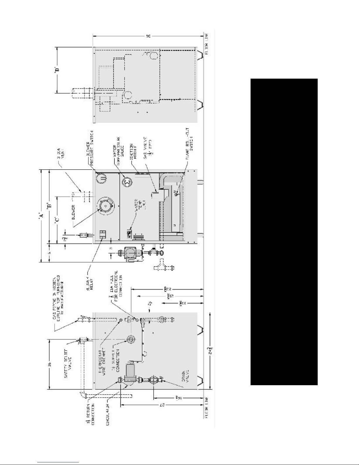
Figure 1: Elevation Views
3
I. Pre-Installation
WARNING
Carefully read all instructions before
installing boiler. Failure to follow all
instructions in proper order can cause
personal injury or death.
A. Inspect shipment carefully for any signs of damage. All
equipment is carefully manufactured, inspected and
packed. Our responsibility ceases upon delivery of
boiler to carrier in good condition. Any claim for damage
or shortage in shipment must be filed immediately
against carrier by consignee. No claims for variances or
shortages will be allowed by Boiler Manufacturer,
unless presented within sixty (60) days after receipt of
equipment.
B. Installation must conform to the requirements of the
authority having jurisdiction. In the absence of such
requirements, installation must conform to National
Fuel Gas Code, NFPA 54/ANSI Z223.1, and/or CAN/
CGA B149 Installation Codes. Where required by the
authority having jurisdiction, the installation must
conform to the Standard for Controls and Safety
Devices for Automatically Fired Boilers, ANSI/ASME
CSD-1.
C. Appliance is design certified for installation on
combustible flooring. The boiler must not be installed
on carpeting.
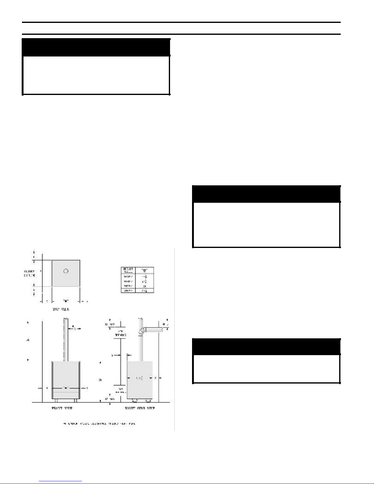
D. Provide clearance between boiler jacket and
combustible material in accordance with local fire
ordinance. See Figure 2 for minimum clearance from
combustible material for closet installation. For alcove
installation provide top clearance of 27 inches and right
side clearance of 6 inches. Recommended service
clearance is 24 inches from left side, right side and front.
Service clearances may be reduced to minimum
clearances to combustible materials.
E. Install on level floor. For basement installation provide
solid base, such as concrete, if floor is not level or if
water may be encountered on floor around boiler.
F. Install near outside wall for through wall venting. Refer
to Section V: Venting, for vent length limitations.
WARNING
Certified as Category III appliance. Install
vent system in accordance with Section
V: Venting. Do not vent using masonry
chimney, Type B gas vent, or other
Category I venting system.
G. Protect gas ignition system components from water
(dripping, spraying, rain, etc.) during boiler operation
and service (circulator replacement, condensate trap,
control replacement, etc.).
H. Provide combustion and ventilation air in accordance
with applicable provisions of local building codes, or
National Fuel Gas Code, NFPA 54/ANSI Z223.1,
Section 5.3, Air for Combustion and Ventilation, or
Sections 7.2, 7.3 or 7.4 of CAN/CGA B149 Installation
Codes.
WARNING
Adequate combustion and ventilation air
must be provided to assure proper
combustion.
The following guideline is based on the National Fuel
Gas Code, NFPA 54/ANSI Z223.1.
1. Determine volume of space (boiler room). Rooms
communicating directly with space (through
openings not furnished with doors) are considered
part of space.
Figure 2: Minimum Clearances to Combustible
Construction for Closet Installation
Volume [ft³] = Length [ft] x Width [ft] x Height [ft]
4
2. Determine Total Input of all appliances in space.
Round result to nearest 1,000 Btu per hour (Btuh).
3. Determine type of space. Divide Volume by Total
Input.
a. If result is greater than or equal to 50 ft³ per 1,000
Btuh, space is considered an unconfined space.
b. If result is less than 50 ft³ per 1,000 Btuh, space is
considered a confined space.
4. Determine building type. A building of unusually
tight construction has the following characteristics:
a. Direct communication with outdoors. Minimum
free area of 1 square inch per 4,000 Btu per hour
input of all equipment in space.
b. Vertical ducts. Minimum free area of 1 square
inch per 4,000 Btu per hour input of all equipment
in space. Duct cross-sectional area shall be same
as opening free area.
c. Horizontal ducts. Minimum free area of 1 square
inch per 2,000 Btu per hour input of all equipment
in space. Duct cross-sectional area shall be same
as opening free area.
a. Walls and ceiling exposed to outside atmosphere
have a continuous water vapor retarder with a
rating of 1 perm or less with openings gasketed
and sealed, and;
b. Weather-stripping has been added on openable
windows and doors, and;
c. Caulking or sealants applied in joints around
window and door frames, between sole plates
and floors, between wall-ceiling joints, between
wall panels, at plumbing and electrical
penetrations, and at other openings.
5. For boiler located in an unconfined space in a
building of other than unusually tight construction,
adequate combustion and ventilation air is normally
provided by fresh air infiltration through cracks
around windows and doors.
6. For boiler located within unconfined space in
building of unusually tight construction or within
confined space, provide outdoor air through two
permanent openings which communicate directly or
by duct with the outdoors or spaces (crawl or attic)
freely communicating with the outdoors. Locate one
opening within 12 inches of top of space. Locate
remaining opening within 12 inches of bottom of
space. Minimum dimension of air opening is 3
inches. Size each opening per following:
Alternate method for boiler located within confined
space. Use indoor air if two permanent openings
communicate directly with additional space(s) of
sufficient volume such that combined volume of all
spaces meet criteria for unconfined space. Size each
opening for minimum free area of 1 square inch per
1,000 Btu per hour input of all equipment in spaces,
but not less than 100 square inches.
7. Ventilation Duct Louvers and Grilles. Equip outside
openings with louvers to prevent entrance of rain
and snow, and screens to prevent entrance of
insects and rodents. Louvers and grilles must be
fixed in open position or interlocked with equipment
to open automatically before burner operation.
Screens must not be smaller than ¼ inch mesh.
Consider the blocking effect of louvers, grilles and
screens when calculating the opening size to provide
the required free area. If free area of louver or grille is
not known, assume wood louvers have 20-25 percent
free area and metal louvers and grilles have 60-75
percent free area.
I. Do not install boiler where gasoline or other flammable
vapors or liquids, or sources of hydrocarbons (i.e.
bleaches, cleaners, chemicals, sprays, paint removers,
fabric softeners, etc.) are used or stored.
II. Unpack Boiler
CAUTION
Do not drop boiler. Do not bump boiler
jacket against floor.
A. Move boiler to approximate installed position.
B. Remove all crate fasteners.
C. Lift outside container and remove with all other inside
protective spacers and bracing. Save two of the
wooden slats from the container sleeve for use in
Paragraphs E and F.
D. Remove all boiler hold-down fasteners.
E. Tilt the boiler to one side and slide a wooden slat under
the two raised feet.
F. Tilt the boiler to the other side and slide another
wooden slat under the two raised feet.
G. Slide the boiler forward or backward off the skid using
the two wooden slats as runners.
H. Move boiler to its permanent location.
5
III. Water Piping and Trim
CAUTION
Failure to properly pipe boiler may result in
improper operation and damage to boiler or
building.
A. Design and install boiler and system piping to prevent
oxygen contamination of boiler water.
CAUTION
Oxygen contamination of boiler water will
cause corrosion of iron and steel boiler
components, and can lead to boiler failure.
Burnham's standard warranty does not
cover problems caused by oxygen
contamination of boiler water.
F. Space heating and domestic water heating with Alliance
water heater. Install Alliance water heater as a separate
heating zone. Refer to Alliance Installation, Operating and
Service Instructions for additional information.
G. If boiler is used in connection with refrigeration systems,
boiler must be installed with chilled medium piped in
parallel with the heating boiler using appropriate valves to
prevent chilled medium from entering boiler, see Figure 4.
Also consult I=B=R Installation and Piping Guides.
H. If boiler is connected to heating coils located in air
handling units where they may be exposed to refrigerated
air, boiler piping must be equipped with flow control
valves to prevent gravity circulation of boiler water during
operation of cooling system.
I. Use a boiler bypass if the boiler is to be operated in a
system which has a large volume or excessive radiation
where low boiler water temperatures may be encountered
(i.e. converted gravity circulation system, etc.).
Oxygen contamination sources are system leaks
requiring addition of makeup water, fittings, and oxygen
permeable materials in distribution system. Eliminate
oxygen contamination by repairing system leaks,
repairing fittings, and using nonpermeable materials in
distribution system.
B. Connect system supply and return piping to boiler. See
Figure 3. Also consult I=B=R Installation and Piping
Guides. Maintain minimum ½ inch clearance from hot
water piping to combustible materials.
C. Install Circulator with flanges, gaskets and bolts
provided. Five foot circulator harness allows circulator
to be mounted on supply or return. Connect harness to
circulator and secure any excess conduit.
D. Install Safety Relief Valve. See Figure 3. Safety Relief
Valve must be installed with spindle in vertical position.
Installation of the relief valve must be consistant with
the ANSI/ASME Boiler and Pressure Vessel Code,
Section IV.
WARNING
Safety relief valve discharge piping must be
piped near floor to eliminate potential of
severe burns. Do not pipe in any area
where freezing could occur. Do not install
any shut-off valves.
Install pipe tee between circulator and boiler return along
with second tee in supply piping as shown in Figure 3.
Bypass should be same size as the supply and return lines
with valves located in bypass and supply outlet as
illustrated in Figure 3 in order to regulate water flow to
maintain higher boiler water temperatures.
After the boiler is operational (reference Section VII.
System Start-Up) set by-pass and boiler supply valves to
half throttle position to start. Operate boiler until system
water temperature reaches normal operating range.
Adjust valves to provide 180° to 200°F supply water
temperature. Opening the boiler supply valve will raise
system temperature, while opening the by-pass valve will
lower system supply temperature.
J. A hot water boiler installed above radiation level must be
provided with a low water cut-off device as part of
installation.
K. Oil, grease, and other foreign materials which
accumulate in new hot water boilers and a new or
reworked system should be boiled out, and then
thoroughly flushed. A qualified water treatment chemical
specialist should be consulted for recommendations
regarding appropriate chemical compounds and
concentrations which are compatible with local
environmental regulations.
L. After the boiler and system have been cleaned and
flushed, and before refilling the entire system add
appropriate water treatment chemicals, if necessary, to
bring the pH between 7 and 11.
E. Install Drain Valve in ¾" NPT connection in tee
provided. See Figure 1.
6

Figure 3: Recommended Boiler Piping For Series - Loop Hot Water Heating Systems
Figure 4: Recommended Piping for Combination Heating & Cooling (Refrigeration) Systems
7
IV. Gas Piping
A. Size gas piping. Design system to provide adequate
gas supply to boiler. Consider these factors:
1. Allowable pressure drop from point of delivery to
boiler. Maximum allowable system pressure is ½
psig. Actual point of delivery pressure may be less;
contact gas supplier for additional information.
Minimum gas valve inlet pressure is listed on
rating label.
2. Maximum gas demand. Table 1 lists boiler input
rate. Also consider existing and expected future gas
utilization equipment (i.e. water heater, cooking
equipment).
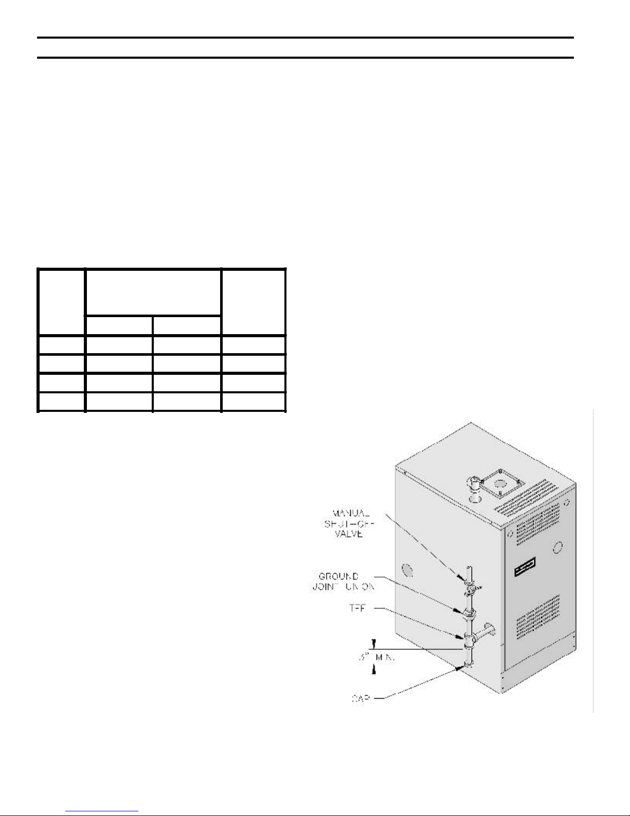
Table 1: Rated Input
Boiler
Model
Number
Natural Gas LP/Propane
203PV 62 24¾ ½
204PV 96 38½ ½
Input Rate
[cubic feet per hour]
Gas
Connection
Size
3. Install sediment trap, ground-joint union and manual
shut-off valve upstream of boiler gas control valve
and outside jacket. See Figure 6.
4. All above ground gas piping upstream from manual
shut-off valve must be electrically continuous and
bonded to a grounding electrode. Do not use gas
piping as grounding electrode. Refer to National
Electrical Code, ANSI/NFPA 70 and/or CSA C22
Electrical Code.
C. Pressure test. The boiler and its gas connection must
be leak tested before placing boiler in operation.
1. Protect boiler gas control valve. For all testing over
½ psig, boiler and its individual shut-off valve must
be disconnected from gas supply piping. For testing
at ½ psig or less, isolate boiler from gas supply
piping by closing boiler's individual manual shut-off
valve.
2. Locate leaks using approved combustible gas
detector, soap and water, or similar nonflammable
solution. Do not use matches, candles, open flames,
or other ignition source.
205PV 130 52 ½
206PV 164 65¾ ½
3. Length of piping and number of fittings. Refer to
Table 2 for maximum capacity of Schedule 40 pipe.
Table 3 lists equivalent pipe length for standard
fittings.
4. Specific gravity of gas. Gas piping systems for gas
with a specific gravity of 0.70 or less can be sized
directly from Table 2, unless authority having
jurisdiction specifies a gravity factor be applied. For
specific gravity greater than 0.70, apply gravity
factor from Table 4. If exact specific gravity is not
shown choose next higher value.
For materials or conditions other than those listed
above, refer to National Fuel Gas Code, NFPA 54/
ANSI Z223.1, or size system using standard
engineering methods acceptable to authority having
jurisdiction.
B. Connect boiler gas valve to gas supply system.
1. Use methods and materials in accordance with local
plumbing codes and requirements of gas supplier.
In absence of such requirements, follow National
Fuel Gas Code, NFPA 54/ANSI Z223.1 and/or
CAN/CGA B149 Installation Codes.
2. Use thread (joint) compounds (pipe dope) resistant
to action of liquefied petroleum gas.
Figure 6: Recommended Gas Piping
8
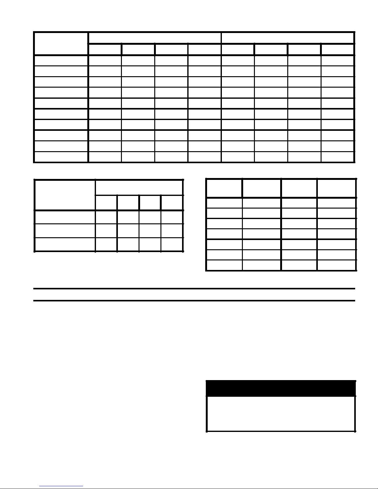
Table 2: Maximum Capacity of Schedule 40 Pipe in CFH For Gas Pressures of 0.5 psig or Less
Length
[Feet]
10 132 278 520 1,050 175 360 680 1,400
20 92 190 350 730 120 250 465 950
30 73 152 285 590 97 200 375 770
40 63 130 245 500 82 170 320 660
50 56 115 215 440 73 151 285 580
60 50 105 195 400 66 138 260 530
70 46 96 180 370 61 125 240 490
80 43 90 170 350 57 118 220 460
90 40 84 160 320 53 110 205 430
100 38 79 150 305 50 103 195 400
0.3 inch w.c. Pressure Drop 0.5 inch w.c. Pressure Drop
½ ¾ 1 1¼ ½ ¾ 1 1¼
Table 3: Fitting Equivalent Lengths Table 4: Specific Gravity Correction Factors
Nominal Pipe Size
Fitting
½ ¾ 1 1¼
45° Ell 0.7 1 1.2 1.6
90° Ell 1.6 2.1 2.6 3.5
Tee (As Elbow) 3.1 4.1 5.2 6.9
Specific
Gravity
0.50 1.10 1.30 1.07
0.55 1.04 1.40 1.04
0.60 1.00 1.50 1.00
0.65 0.96 1.60 0.97
0.70 0.93 1.70 0.94
Correction
Factor
Specific
Gravity
Correction
Factor
V. Venting
A. General Guidelines.
1. Vent system installation must be in accordance with
National Fuel Gas Code, NFPA 54/ANSI Z221.3,
Part 7, Venting of Equipment; and/or CAN/CGA
B149 Installation Codes, Section 7, Venting Systems
and Air Supply for Appliances; or applicable
provisions of local building codes. Contact local
building or fire officials about restrictions and
installation inspection in your area.
2. This appliance requires a Special Gas Vent. Use Vent
Connector and Vent Terminal in Vent Accessory
Carton provided with boiler (See Repair Parts, Key
No. 8). The product is designed to use Burnham
supplied AL 29-4C® Stainless Steel vent system
components. The following manufacturers offer
similar AL 29-4C® components and are approved for
use with this product: Heat-Fab Inc. - Saf-T-Vent,
0.75 0.90
0.80 0.87
Flex-L International Inc., - Star-34, Protech Systems,
Inc. - FasNSeal™, and Z-Flex U. S., Inc. - Z-Vent.
The use of these alternate manufacturer's venting
systems will require adapters to connect to the
Burnham supplied vent connector and vent terminal.
These adapters are not supplied with this unit and
should be obtained from the supplier of the alternate
manufacturer's venting system. See Table 5 for
complete list of Burnham Vent System Components.
WARNING
Do not use this appliance with nonmetallic
vent systems such as Hart & Cooley
Ultravent, Plexco Plexvent, or SelkirkMetalbestos Sel-Vent.
9
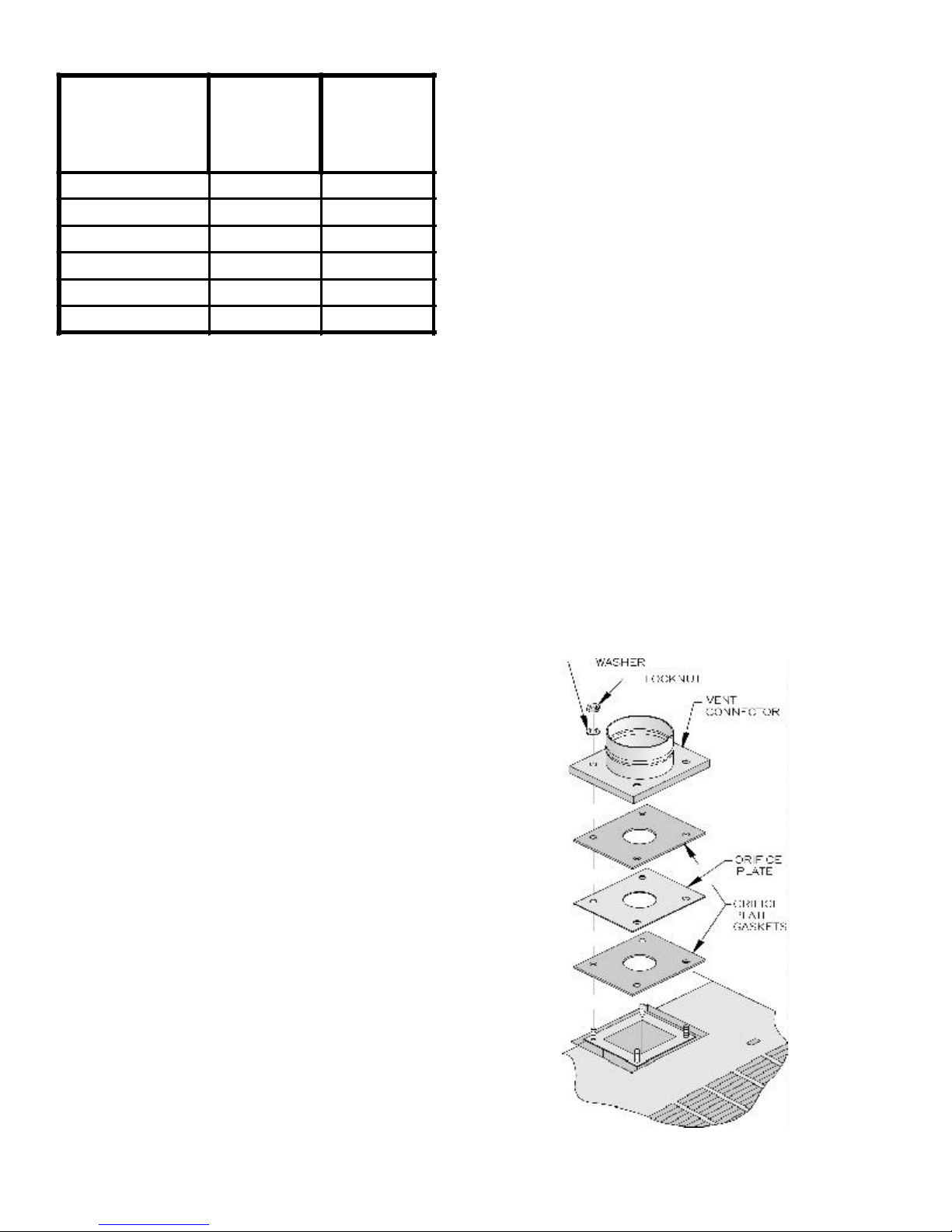
Table 5: Burnham Vent System Components
Burnham
Vent System
Component
*Cartoned
Part
Number
3" Dia. Pipe x 1 Ft 61160112 8116135
3" Dia. Pipe x 3 Ft 61160101 8116058
3" Dia. Pipe x 4 Ft ** 8116176
3" Dia. Pipe x 5 Ft 61160111 8116059
3" Dia. 90° Elbow 61160121 8116060
3" Dia. 45° Elbow 61160131 8116061
Burnham
Component
Part
Number
* Complete with Locking Band(s)
* * 6116033 Contains (4) 4 ft. lengths
6116040 Contains (2) 4 ft. lengths
3. Vent length restrictions are based on equivalent feet
of vent pipe (total length of straight pipe in feet plus
5 equivalent feet for each 45° or 90° elbow). Do not
exceed the maximum certified vent length of 25
equivalent feet. The minimum certified vent length is
7 equivalent feet. Do not include vent terminal or
vent connector in equivalent feet calculations.
4. Do not install venting system components on the
exterior of the building except as specifically required
by these instructions.
B. Removal of Existing Boiler. For installations not
involving the replacement of an existing boiler, proceed
to Step C.
When an existing boiler is removed from a common
venting system, the common venting system is likely to
be too large for proper venting of the remaining
appliances. At the time of removal of an existing boiler,
the following steps shall be followed with each
appliance remaining connected to the common venting
system placed in operation, while the other appliances
remaining connected to the common venting system are
not in operation:
(a) Seal any unused openings in the common venting
system.
(b)Visually inspect the venting system for proper size
and horizontal pitch and determine there is no
blockage or restriction, leakage, corrosion, and other
deficiencies which could cause an unsafe condition.
(c) Insofar as is practical, close all building doors and
windows and all doors between the space in which
the appliances remaining connected to the common
venting system are located and other spaces of the
building. Turn on clothes dryers and any appliance
not connected to the common venting system. Turn
on any exhaust fans, such as range-hoods and
bathroom exhausts, so they will operate at maximum
speed. Do not operate a summer exhaust fan. Close
fireplace dampers.
(d)Place in operation the appliance being inspected.
Follow the Lighting (or Operating) Instructions.
Adjust thermostat so appliance will operate
continuously.
(e) Test for spillage at the drafthood relief opening after
5 minutes of main burner operation. Use the flame of
a match or candle, or smoke from a cigarette, cigar or
pipe.
(f) After it has been determined that each appliance
remaining connected to the common venting system
properly vents when tested as outlined above,
return doors, windows, exhaust fans, fireplace
dampers and any other gas burning appliance to
their previous conditions of use.
(g)Any improper operation of the common venting
system should be corrected so the installation
conforms with the National Fuel Gas Code, NFPA
54/ANSI Z223.1. When resizing any portion of the
common venting system, the common venting
system should be resized to approach the minimum
size as determined using the appropriate tables in
Part II in the National Fuel Gas Code, NFPA 54/
ANSI Z223.1.
C. Install Vent Connector.
1. Remove vent connector from vent accessory carton.
2. Remove gaskets, orifice plate and hardware from
blower outlet flange.
3. Assemble orifice plate gaskets, orifice plate, and
vent connector. See Figure 7.
4. Secure vent connector with washers and locknuts.
Figure 7: Vent Connector Installation
10
 Loading...