

Page 1
DNAGNITAREPO,NOITALLATSNI
ROFSNOITCURTSNIECIVRES
2SEIRES
®
)Bledom(
RELIOBDERIF-SAG
,reliobnonoitamrofnignikeesnehW.rotcartnocgnitaehruoyllac,reliobotsriaperroecivresroF
.lebaLgnitaRnonwohssarebmuNlaireSdnarebmuNledoMrelioBedivorp
rebmuNledoMrelioB
rebmuNlaireSrelioB
etaDnoitallatsnI
2
rotcartnoCgnitaeH
rebmuNenohP
sserddA
81417032R24-10/08
Price - $3.00
Page 2
NOTE: The equipment shall be installed in accordance with those installation regulations in force in the area where the
installation is to be made. These shall be carefully followed in all cases. Authorities having jurisdiction shall be consulted before
installations are made.
All wiring on boilers installed in the USA shall be made in accordance with the National Electrical Code and/or local regulations.
All wiring on boilers installed in Canada shall be made in accordance with the Canadian Electrical Code and/or local regulations.
The New York City Department of Buildings has approved the Series 2B boiler: Approval No. MEA 96-96-E
The City of New York requires a Licensed Master Plumber supervise the installation of this product.
The Massachusetts Board of Plumbers and Gas Fitters has approved the Series 2B boiler. See the Massachusetts Board of
Plumbers and Gas Fitters website, http://license.reg.state.ma.us/pubLic/pb_pre_form.asp for the latest Approval Code or ask
your local Sales Representative.
The Commonwealth of Massachusetts requires this product to be installed by a Licensed Plumber or Gas Fitter.
Table of Contents
I. Installation Instructions ................... 4
II. Operating Instructions .....................18
III. Trouble Shooting..............................25
IV. Service ..............................................26
V. Repair Part .......................................
29
VI. Appendix
Low Water Cut Off ...........................51
The following dened terms are used throughout this manual to bring attention to the presence of hazards of various risk levels, or
to important information concerning the life of the product.
DANGER
Indicates presence of a hazard which will cause
severe personal injury, death or substantial
property damage if ignored.
WARNING
Indicates presence of a hazard which can cause
severe personal injury, death or substantial
property damage if ignored.
Indicates presence of a hazard which will or can
cause minor personal injury or property damage
if ignored.
Indicates special instructions on installation,
operation, or maintenance which are important
but not related to personal injury hazards.
CAUTION
NOTICE
FAILURE TO FOLLOW ALL INSTRUCTIONS IN PROPER ORDER CAN CAUSE PERSONAL INJURY OR
DEATH. READ ALL INSTRUCTIONS BEFORE INSTALLING.
SERVICE ON THIS BOILER SHOULD BE UNDERTAKEN ONLY BY TRAINED AND SKILLED PERSONNEL.
KEEP BOILER AREA CLEAR AND FREE FROM COMBUSTIBLE MATERIALS, GASOLINE AND OTHER
FLAMMABLE VAPORS AND LIQUIDS.
DO NOT PLACE ANY OBSTRUCTION IN THE BOILER ROOM THAT WILL HINDER THE FLOW OF
COMBUSTION AND VENTILATING AIR.
2
WARNING
WARNING
Page 3

WARNING
READ THESE INSTRUCTIONS CAREFULLY BEFORE PROCEEDING WITH THE INSTALLATION OF BOILER.
POST INSTRUCTIONS NEAR BOILER FOR REFERENCE BY OWNER AND SERVICE TECHNICIAN. MAINTAIN
INSTRUCTIONS IN LEGIBLE CONDITION.
Boiler
Model
Number
202 18-3/4 10-3/4 6-3/8 4 45-5/8 8-1/2 10 [3] 1/2 2.5 3" dia. x 15 ft. 212
202X 20 12 6 4 45-5/8 8-1/2 4-3/4 1/2 3.2 4" dia. x 15 ft. 262
203 20 12 6 4 45-5/8 8-1/2 4-3/4 1/2 3.2 4" dia. x 15 ft. 262
204 23-1/4 15-1/4 7-5/8 5 47-1/8 9-1/8 4-3/4 1/2 4 5" dia. x 15 ft. 306
205 26-1/2 18-1/2 9-1/4 6 48-1/2 9-3/4 5-1/4 1/2 4.7 6" dia. x 15 ft. 354
206 29-3/4 21-3/4 10-7/8 6 48-1/2 9-3/4 5-1/4 1/2 5.5 6" dia. x 15 ft. 414
207 33 25 12-1/2 7 50-1/8 10-3/8 6-5/8 3/4 6.2 7" dia. x 15 ft. 458
208 36-1/4 28-1/4 14-1/8 7 50-1/8 10-3/8 6-5/8 3/4 7 7" dia. x 15 ft. 514
209 39-1/2 31-1/2 15-3/4 8 52 11 7-1/4 3/4 7.7 8" dia. x 15 ft. 550
210 42-3/4 34-3/4 17-3/8 8 52 11 7-1/4 3/4 8.5 8" dia. x 15 ft. 608
[1] 15' chimney height is from bottom of draft hood opening to top of chimney.
[2] Refer to the National Fuel Gas Code for equivalent areas of circular and rectangular ue linings.
Maximum Allowable Working Pressure - 30 PSI (Water Only)
[3] 202 only. Dimension 'G' includes allowance for 4" x 3" reducer furnished with boiler. See Figure 8.
A B C D E F G
Dimensions [Inches] Gas
Connection
For Automatic
Gas Valve
Water
Content
[gallons]
Recommended
Vent Size
[1] [2]
Approx.
Shipping
Figure 1
Weight
[lb.]
3
Page 4

I . Installation Instructions
1. INSPECT SHIPMENT carefully for any signs of
damage. All equipment is carefully manufactured,
inspected and packed. Our responsibility ceases upon
delivery of Boiler to the carrier in good condition. Any
claims for damage or shortage in shipment must be led
immediately against the carrier by the consignee. No
claims for variances or shortages will be allowed by
Boiler Manufacturer unless presented within sixty (60)
days after receipt of equipment.
2. BOILER INSTALLATION must conform to the
requirements of the authority having jurisdiction, or in
the absence of such requirements, to:
U.S.A. - National Fuel Gas Code, ANSI Z223.1.
When required by the authority having juris-
diction, the installation must conform to
ANSI/ASME No. CSD-1.
CANADA - "Installation Codes for Natural and LP Gas
Burning Appliances and Equipment, CAN/
CSA-B149.1.
3. These Gas Boilers are DESIGN CERTIFIED FOR
INSTALLATION ON COMBUSTIBLE FLOORING.
DO NOT INSTALL THESE BOILERS ON
CARPETING.
NOTICE
Do not drop boiler. Do not bump boiler jacket
against oor.
4. LOCATE BOILER in front of or behind installation
position before removing Crate. Locate on a level oor
as close to chimney as possible. For basement
installations, provide a solid base such as concrete, if
oor is not level or if water may be encountered on
oor around Boiler.
The boiler shall be installed such that the gas ignition
system components are protected from water (dripping,
spraying, rain, etc.) during boiler operation and service
(circulator replacement, control replacement, etc.).
DANGER
Do not install boiler where gasoline or other
ammable vapors or liquids, or sources of
hydrocarbons (i.e. bleaches, cleaners, chemicals,
sprays, paint removers, fabric softeners, etc.) are
used or stored.
5. REMOVE CRATE -
A. Remove all crate fasteners. Lift off outside
container.
B. Remove all screws and brackets securing boiler to
skid.
C. Save two of the wooden slats from the container
sleeve for use in Steps D & E.
D. Tilt the boiler to one side and slide a wooden slat
under the two raised feet.
E. Tilt the boiler to the other side and slide another
wooden slat under the two raised feet.
F. Slide the boiler forward or backward off the skid
using the two wooden slats as runners.
6. Move boiler to permanent position.
7. PROVIDE CLEARANCE and AIR for COMBUS-
TION and VENTILATION.
WARNING
Adequate combustion and ventilation air must be
provided to assure proper combustion.
A. CLEARANCES
1. ALL INSTALLATIONS - Practical service
clearances must be considered (see Figure 1). A
minimum of 24" (6.0cm) from the left side and
front jacket panels is recommended for servicing
but may be reduced to minimum shown in
Figure 2. Subject to boiler and system piping,
left side clearance may be reduced to 1" (2.5cm)
if right side clearance is increased to 9"
(22.9cm).
2. ALCOVE INSTALLATIONS - An alcove is
considered a closet as shown in Figure 2 less
front. Height clearance may be reduced to 27"
(68.6cm).
3. UNCONFINED SPACE (see denition,
paragraph (B) below) - Height clearance may be
reduced to 27" (68.6cm).
B. PROVIDE COMBUSTION AND VENTILATION
AIR in accordance with applicable provisions of
local building codes, or: U.S.A. - National Fuel
Gas Code, NFPA 54/ANSI Z223.1, Canada -
Natural and Propane Gas Installation Code, CAN/
CSA-B149.1.
1. CLOSET INSTALLATIONS (conned space) in
a building of other than unusually tight
construction (see denition below), provide
combustion and ventilation air as shown in
Figure 2.
2. Installations other than closet in paragraph (1) :
a. Determine volume of space (boiler room).
Rooms communicating directly with space
(through openings not furnished with doors)
are considered part of space.
4
Page 5
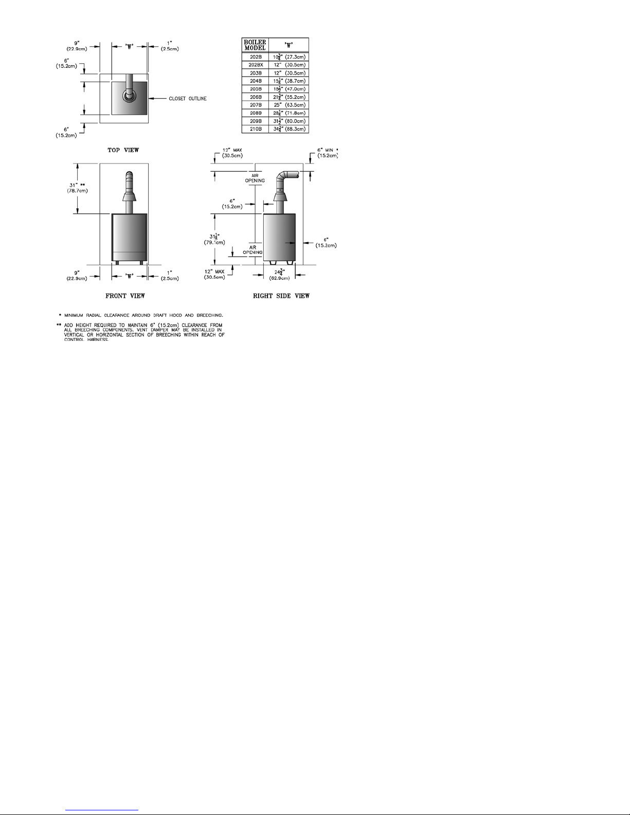
Figure 2: Minimum Clearances
Volume [ft³](m
3
) = Length [ft](m) x Width
[ft](m) x Height [ft](m)
b. Determine Total Input of all appliances in
space. Round result to nearest 1,000 Btu per
hour (Btuh).
c. Determine type of space. Divide Volume by
Total Input.
i. If result is greater than or equal to 50 ft³
(1.4m3) per 1,000 Btuh, space is
considered an unconned space.
ii. If result is less than 50 ft³ (1.4m3) per
1,000 Btuh, space is considered a conned
space.
d. Determine building type. A building of
unusually tight construction has the
following characteristics:
i. Walls and ceiling exposed to outside
atmosphere have a continuous water vapor
retarder with a rating of 1 perm or less
with openings gasketed and sealed, and
ii. Weather-stripping has been added on
openable windows and doors, and
iii. Caulking or sealants applied in joints
around window and door frames, between
sole plates and oors, between wall-
ceiling joints, between wall panels, at
plumbing and electrical penetrations, and
at other openings.
e. For boiler located in a building of other than
unusually tight construction, adequate
combustion and ventilation air is normally
provided by fresh air inltration through
cracks around windows and doors.
f. For boiler located
in building of unusually
tight construction, provide outdoor air
through two permanent openings which
communicate directly or by duct with the
outdoors or spaces (crawl or attic) freely
communicating with the outdoors. Locate
one opening within 12 inches (30.5cm) of
top of space. Locate remaining opening
within 12 inches (30.5cm) of bottom of
space. Minimum dimension of air opening is
3 inches (7.6cm). Size each opening per
following:
i. Direct communication with outdoors.
Minimum free area of 1 square inch
(6.5cm2) per 4,000 Btu per hour input of
all equipment in space.
ii. Vertical ducts. Minimum free area of 1
square inch (6.5cm2) per 4,000 Btu per
hour input of all equipment in space. Duct
cross-sectional area shall be same as
opening free area.
iii. Horizontal ducts. Minimum free area of 1
square inch (6.5cm2) per 2,000 Btu per
hour input of all equipment in space. Duct
cross-sectional area shall be same as
opening free area.
g. Ventilation Duct Louvers and Grilles. Equip
outside openings with louvers to prevent
entrance of rain and snow, and screens to
prevent entrance of insects and rodents.
Louvers and grilles must be xed in open
position or interlocked with equipment to
open automatically before burner operation.
Screens must not be smaller than ¼ inch
mesh.
Consider the blocking effect of louvers,
grilles and screens when calculating the
opening size to provide the required free
area. If free area of louver or grille is not
known, assume wood louvers have 20-25
percent free area and metal louvers and
grilles have 60-75 percent free area.
8. CONNECT GAS SERVICE from Meter to gas control
assembly in accordance with Local Piping Codes and
requirements of Gas Company, see Figure 1. They may
require piping of larger size than Control Assembly
Connection, especially if run from meter is long or
includes several elbows. (See Figure 1 for size of Gas
Connection to gas control assembly).
5
Page 6
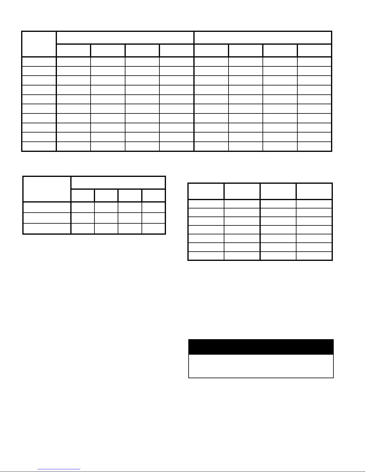
Table 1: Maximum Capacity of Schedule 40 Pipe in CFH For Natural Gas Pressures of ½ psig or Less
Length
[Feet]
10 132 278 520 1,050 175 360 680 1,400
20 92 190 350 730 120 250 465 950
30 73 152 285 590 97 200 375 770
40 63 130 245 500 82 170 320 660
50 56 115 215 440 73 151 285 580
60 50 105 195 400 66 138 260 530
70 46 96 180 370 61 125 240 490
80 43 90 170 350 57 118 220 460
90 40 84 160 320 53 110 205 430
100 38 79 150 305 50 103 195 400
Table 2: Equivalent Length of Fittings
0.3 Inch w.c. Pressure Drop 0.5 Inch w.c. Pressure Drop
½ ¾ 1 1¼ ½ ¾ 1 1¼
Table 3: Specic Gravity Correction Factors for
Natural Gas
Nominal Pipe Size
Fitting
½ ¾ 1 1¼
45° Ell 0.7 1 1.2 1.6
90° Ell 1.6 2.1 2.6 3.5
Tee (As Elbow) 3.1 4.1 5.2 6.9
This piping is to be supplied by the installer and must
include a trap, a ground joint union and a manual
Specic
Gravity
0.50 1.10 1.30 1.07
0.55 1.04 1.40 1.04
0.60 1.00 1.50 1.00
0.65 0.96 1.60 0.97
0.70 0.93 1.70 0.94
0.75 0.90 --- ---
0.80 0.87 --- ---
Correction
Factor
Specic
Gravity
shutoff valve upstream of the gas control assembly
outside of the jacket when codes require, see Figure 1.
A pipe thread compound resistant to the action of
liqueed petroleum gases should be applied to all
threaded joints in the gas piping. Pressure testing of the
Gas Supply Piping Boiler and its connections is
required before placing the boiler in operation.
The boiler and shutoff valve must be disconnected from
the gas supply piping system during any pressure
testing at pressures greater than ½ psig (3.5kPa).
A. Allowable loss of pressure to assure a burner
manifold pressure of 3½" (8.9cm) water for natural
gas.
B. Supply of gas to be provided in cubic feet.
C. Length of piping and number of ttings.
D. Specic gravity of gas.
E. Correction factor for specic gravity.
9. BOILER PIPING
The boiler must be isolated from the gas supply piping
system by closing its individual manual shutoff valve
CAUTION
during any pressure testing of the gas supply piping
system at pressures equal to or less than ½ psig
(3.5kPa).
RECOMMENDED SIZING OF GAS SUPPLY
PIPING TO BOILER FOR NATURAL GAS - shall
be such as to provide the required supply of gas without
undue loss of pressure between meter and the boiler.
Gas supply piping should be sized in accordance with
the Tables 1, 2 and 3. The following shall be taken into
account:
Failure to properly pipe boiler may result in
improper operation and damage to boiler or
building.
A. CLEARANCES - Hot water pipes do not require
clearance from combustible construction.
B. Install drain valve and safety relief valve as shown
in Figures 1 and 3. Note - Safety relief valve must
be in vertical position.
C. Pipe safety relief valve discharge to oor.
Correction
Factor
6
Page 7
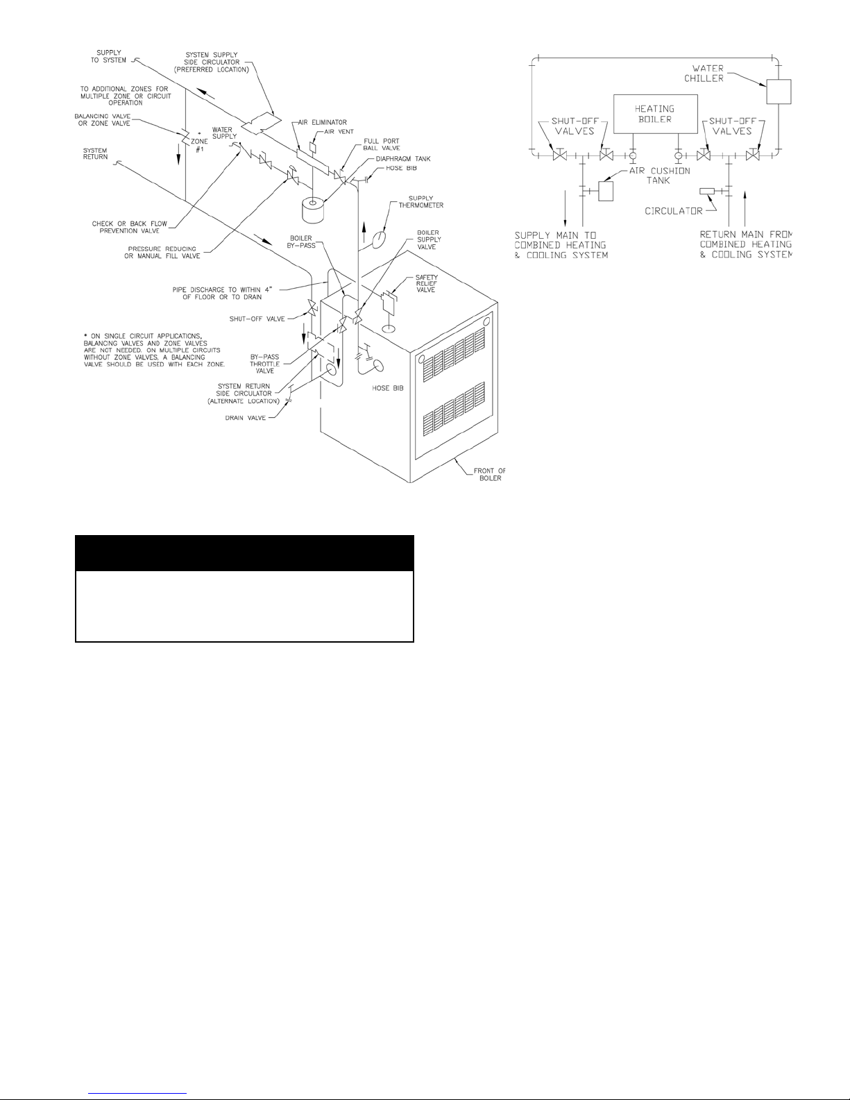
Figure 3: Recommended Water Piping for
Zone Valve Zoned Heating Systems
WARNING
Safety relief valve discharge piping must be
piped near oor to eliminate potential of severe
burns. Do not pipe in any area where freezing
could occur. Do not install any shut-off valves.
D. Install circulator with anges, gaskets and bolts
provided. Five foot long circulator harness allows
circulator to be mounted on supply or return.
Connect harness to circulator and secure any excess
conduit.
E. For heating only system piping, see Figure 3.
Consult also I=B=R Installation Guides.
F. For space heating and domestic water heating with
Alliance SL™ water heater (intermittent circulation
only); install Alliance SL™ water heater as a
separate heating zone. Refer to Alliance SL™
Installation, Operating and Service Instructions for
additional information.
G. If this boiler is used in connection with refrigeration
systems, the boiler must be installed so that the
chilled medium is piped in parallel with the heating
boiler using appropriate valves to prevent the chilled
medium from entering the boiler, see Figure 4. Also
consult I=B=R Installation and Piping Guides.
If this Boiler is connected to heating coils located in
air handling units where they may be exposed to
refrigerated air, the boiler piping must be equipped
Figure 4: Recommended Piping
for Combination Heating & Cooling
(Refrigeration) Systems
with ow control valves to prevent gravity
circulation of boiler water during the
operation of the cooling system.
H. Use a boiler bypass if the boiler is to be
operated in a system which has a large
volume or excessive radiation where low
boiler water temperatures may be
encountered (i.e. converted gravity
circulation system, etc.).
Install a pipe tee at the boiler return along
with a second tee in the supply piping as shown in
Figure 3. The bypass should be the same size as the
supply and return lines with valves located in the
bypass and supply outlet as illustrated in Figure 3 in
order to regulate water ow to maintain higher
boiler water temperatures.
Set the by-pass and boiler supply valves to a half
throttle position to start. Operate boiler until the
system water temperature is at a normal operating
range.
Adjust the valves to provide 180° to 200°F supply
water temperature. Opening the boiler supply valve
will raise the system temperature, while opening the
by-pass valve will lower the system supply
temperature.
I. A hot water boiler installed above radiation level
must be provided with a low water cutoff device as
part of the installation.
If a low water cut-off is required, it must be
mounted in the system piping above the boiler.
The minimum safe water level of a hot water boiler
is just above the highest water containing cavity of
the boiler; that is, a hot water boiler must be full of
water to operate safely.
Refer to Section VI for low water cut-off piping and
wiring instructions.
J. If it is required to perform a long term pressure test
of the hydronic system, the boiler should rst be
isolated to avoid a pressure loss due to the escape of
air trapped in the boiler.
7
Page 8
To perform a long term pressure test including the
boiler, ALL trapped air must rst be removed from
the boiler.
A loss of pressure during such a test, with no visible
water leakage, is an indication that the boiler
contained trapped air.
K. OXYGEN CORROSION:
Oxygen contamination of the boiler water will cause
corrosion of the iron and steel boiler components,
which can lead to failure. As such, any system must
be designed to prevent oxygen absorption in the rst
place or prevent it from reaching the boiler.
Problems caused by oxygen contamination of boiler
water are not covered by Burnham's standard
warranty.
There are many possible causes of oxygen
contamination such as:
1. Addition of excessive make-up water as a result
of system leaks.
2. Absorption through open tanks and ttings.
3. Oxygen permeable materials in the distribution
system.
In order to insure long product life, oxygen
sources should be eliminated. This can be
accomplished by taking the following measures:
1. Repairing system leaks to eliminate the need for
addition of make-up water.
2. Eliminating open tanks from the system.
3. Eliminating and/or repairing ttings which allow
oxygen absorption.
4. Use of non-permeable materials in the
distribution system.
5. Isolating the boiler from the system water by
installing a heat exchanger.
10. INSTALL DRAFT HOOD without modication on
outlet of ue collector (See Figure 1). Secure with sheet
metal screws.
WARNING
Do not alter boiler draft hood or place any
obstruction or non-approved damper in the
breeching or vent system. Flue gas spillage can
occur. ETL certication will become void.
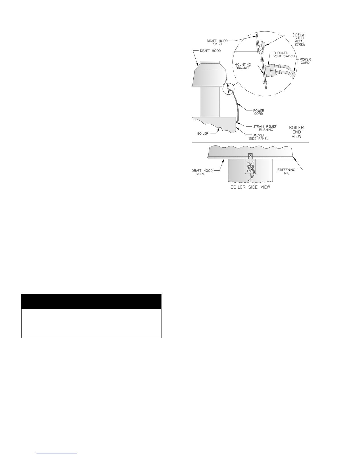
11. INSTALL BLOCKED VENT SWITCH
The blocked vent switch assembly shipped taped to the
top of the boiler includes a power cord and a switch
attached to a mounting bracket. The mounting bracket
has a three tooth staggered comb stamping at one end
with a #10 sheet metal screw in the center tooth.
A. Untape the blocked vent switch assembly from the
top of the boiler and uncoil the power cord.
Figure 6
B. Pinch the black strain relief bushing installed in the
jacket right side panel to dislodge it from the jacket
and pull just enough of the black power cord out so
the blocked vent switch will reach the near side of
the draft hood skirt. Do not pull out more power
cord than necessary.
C. Position the mounting bracket (with switch attached)
onto the lower edge of the draft hood skirt by
locating the center tooth (with the #10 sheet metal
screw) on the outside and the other two teeth inside
the draft hood skirt. See Figure 6.
D. Slide the mounting bracket up tight against the
lower edge of the draft hood skirt, so that the #10
sheet metal screw is above the skirt's stiffening rib.
E. Secure the bracket in this position by tightening the
#10 sheet metal screw against the outer surface of
the draft hood skirt.
F. Reinsert the excess power cord through the jacket
side panel hole to take the slack out of the power
cord running up to the blocked vent switch.
G. Reposition the strain relief bushing around the
power cord at the jacket side panel, pinch the two
halves of the bushing together, and snap it back into
the hole in the jacket side panel to secure the power
cord to the jacket.
H. Be sure the power cord, mounting bracket, and
switch are secure and located as shown in Figure 6.
8
Page 9
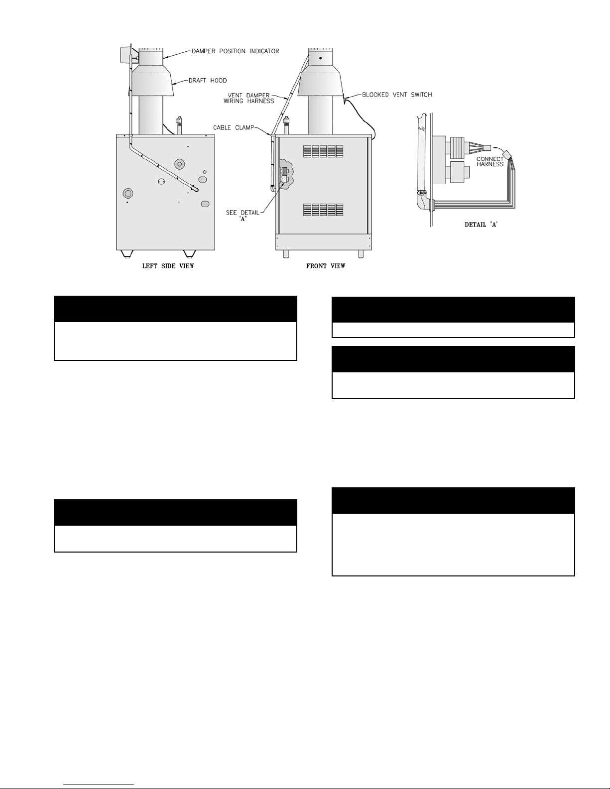
Figure 7: Plug-in Damper Installation
WARNING
Failure to properly install and use this Blocked
Vent Switch may result in property damage,
personal injury or loss of life.
12. TO MEET FEDERALLY MANDATED
EFFICIENCIES, THIS BOILER MUST BE
EQUIPPED WITH A VENT DAMPER.
OPEN THE VENT DAMPER CARTON and remove
the Installation Instructions. READ THE INSTALLATION INSTRUCTIONS THOROUGHLY
proceeding.
The automatic gas control valve supplied on each Series
2™ boiler provides the redundancy referenced in the
vent damper Installation Instructions.
before
CAUTION
Do not use one vent damper to control two heating
appliances.
A. The vent damper should be the same size as the
outlet of the Draft Hood. (See Figure 1) Unpack the
damper carefully - DO NOT FORCE IT CLOSED!
Forcing the damper may damage the gear train and
void the warranty. The damper assembly includes a
prewired connection harness for use on all 24V
Standing Pilot or electronic ignition control systems.
B. Mount the vent damper assembly after the draft
hood, as close to the draft hood as practicable
without modication to the draft hood or vent
damper. (Refer to Figure 7 and to instructions
packed with the vent damper for specic
instructions). This is a must for the wiring harness to
t and the damper position indicator to be visible to
the users.
NOTICE
Provide adequate clearance for servicing.
WARNING
Provide 6" (15.2cm) minimum clearance between
damper and combustible construction.
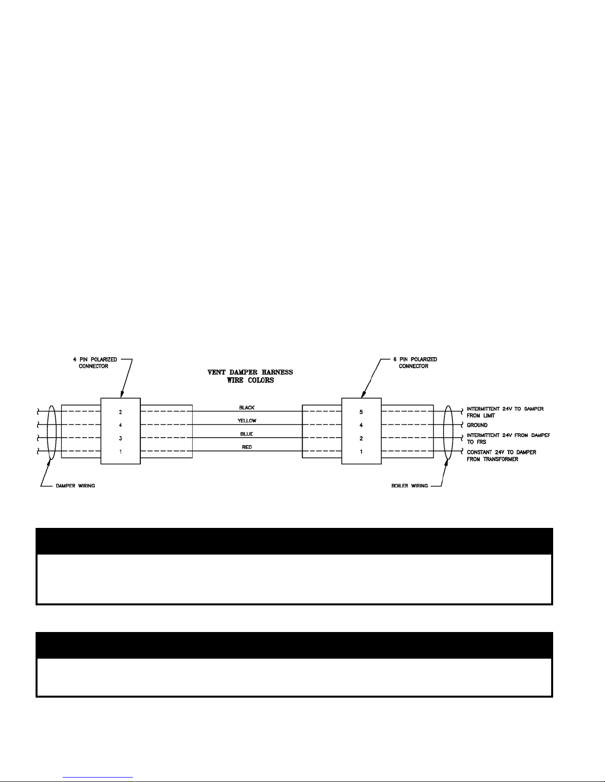
C. Install the 90° BX connector attached to the exible
conduit in the 7/8" knockout on the left side of the
jacket. Plug the factory wired Vent Damper Harness
into the polarized receptacle. Install a cable clamp
around the exible conduit and attach to the Jacket
top panel. (See Figure 7).
NOTICE
Please refer to the specications, installation
instructions and troubleshooting guide packed
in the vent damper carton for complete detailed
installation instructions. Also refer to Figure 7 in
this manual.
D Continuous Ignition (Standing Pilot) Only. Remove
knockout from vent damper blade.
E. Size 202 Only. Install 4" x 3" reducing tting on
vent damper outlet.
13. INSTALL VENT CONNECTOR from reducing
tting (202 Only), draft hood or damper to chimney, see
Figure 8.
9
Page 10
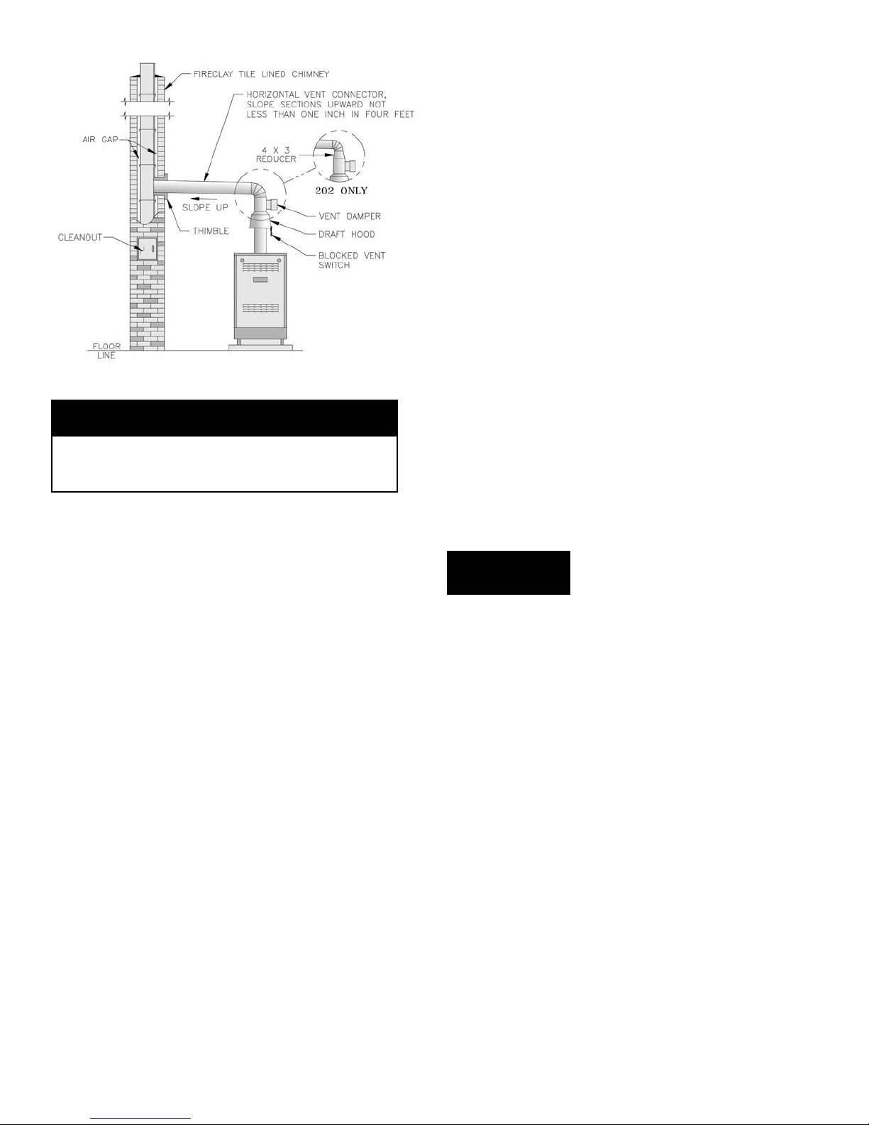
Figure 8: Typical Vent Installation
DANGER
Inspect existing chimney before installing boiler.
Failure to clean or replace perforated pipe or tile
lining will cause severe injury or death.
A. Vent installation shall be in accordance with local
building codes; or the local authority having
jurisdiction; or the National Fuel Gas Code, ANSI
Z223.1/NFPA 54; or the Standard for Chimneys,
Fireplaces, Vents, and Solid Fuel Burning
Appliances, ANSI/NFPA 211. Both of the
aforementioned standards, ANSI Z223.1 and ANSI/
NFPA 211, specify Type B and Type L double wall
metal vents and re clay tile lined masonry
chimneys as suitable chimney constructions for
Category I, draft hood equipped appliances, such as
this Series 2™ boiler. Both standards prohibit the
use of unlined masonry construction as a chimney,
with the exception in ANSI Z223.1/NFPA 54 that
"Where permitted by the authority having
jurisdiction, existing chimneys shall be permitted to
have their use continued when an appliance is
replaced by an appliance of similar type, input
rating, and efciency." ANSI/NFPA 211 prohibits
the use of single wall metal vent as a chimney, while
ANSI Z223.1 allows it under very restrictive
conditions. In Canada refer to the Natural Gas and
LP Installation Code, CAN/CSA-B149.1.
B. Do not connect into same leg of chimney serving an
open replace.
C. Inspect chimney for obstructions or restrictions and
remove. Clean chimney if necessary.
D. Vent pipe to chimney must not be smaller than outlet
on draft hood or damper. Although single wall vent
pipe may be used, Type B is recommended. The
venting system must be arranged so that only the
boiler is served by the damper device. Installation
per paragraph 12 complies with this provision.
E. Where two or more appliances vent into a common
vent, the area of the common vent should at least
equal the area of the largest vent plus 50% of the
area in the additional vents. Do not connect the vent
of this appliance into any portion of mechanical
draft system operating under positive pressure.
F. Vent pipe should have the greatest possible initial
rise above the draft hood consistent with the head
room available and the required clearance from
adjacent combustible building structure. Vent Pipe
should be installed above the bottom of chimney to
prevent blockage.
G. Vent pipe should slope upward from draft hood to
chimney not less than one inch in four feet. Doivent
présenter des tronçons horizontaux dont la pente
montante est d’au moins ¼ po par pied (21 mm/m)
entre la chaudière et l’évent. No portion of vent
pipe should run downward or have dips or sags.
Vent pipe must be securely supported. Les sections
horizontales doivent être supportées pour prévenir le
échissement.
H. Vent pipe must be inserted into but not beyond
inside wall of chimney liner. Seal tight between vent
pipe and chimney.
I. Do not install non-listed (AGA, CGA, CSA, ETL or
UL) vent damper or other obstruction in vent pipe.
WARNING
14. IF AN EXISTING BOILER IS REMOVED -
When an existing boiler is removed from a common
venting system, the common venting system is likely to
be too large for proper venting of the appliances
remaining to it.
At the time of removal of an existing boiler, the
following steps shall be followed with each
appliance remaining connected to the common
venting system placed in operation, while the other
appliances remaining connected to the common
venting system are not in operation:
A. Seal any unused openings in the common venting
system.
B. Visually inspect the venting system for proper size
and horizontal pitch and determine there is no
blockage or restriction, leakage, corrosion, and other
deciencies which could cause an unsafe condition.
C. Insofar as is practical, close all building doors and
windows and all doors between the space in which
the appliances remaining connected to the common
venting system are located and other spaces of the
building. Turn on clothes dryers and any appliance
not connected to the common venting system. Turn
on any exhaust fans, such as range-hoods and
bathroom exhausts, so they will operate at maximum
10
Page 11
speed. Do not operate a summer exhaust fan. Close
replace dampers.
D. Place in operation the appliance being inspected.
Follow the Lighting (or Operating) Instructions.
Adjust thermostat so appliance will operate
continuously.
E. Test for spillage at the draft hood relief opening
after 5 minutes of main burner operation. Use the
ame of a match or candle, or smoke from a
cigarette, cigar or pipe.
F. After it has been determined that each appliance
remaining connected to the common venting system
properly vents when tested as outlined above, return
doors, windows, exhaust fans, replace dampers and
any other gas burning appliance to their previous
conditions of use.
G. Any improper operation of the common venting
system should be corrected so the installation
conforms with the National Fuel Gas Code, ANSI
Z223.1 and/or CAN/CSA B149.1, Installation
Codes. When resizing any portion of the common
venting system, the common venting system should
be resized to approach the minimum size as
determined using the National Fuel Gas Code,
ANSI Z223.1 and/or CAN/CSA B149.1, Installation
Codes.
Au moment du retrait d’une chaudière existante, les
mesures suivantes doivent être prises pour chaque
appareil toujours raccordé au système d’evacuation
commun et qui fonctionne alors que d’autres
appareils toujours raccordés au système
d’évacuation ne fonctionnent pas:
A. Sceller toutes les ouvertures non utilisées du
système d’évacuation.
B. Inspecter de facon visuelle le système d’évcuation
pour déterminer la grosseur et l’inclinaison
horizontale qui conviennent et s’assurer que le
système est exempt d’obstruction, d’étranglement,
de fuite, de corrosion et autres défaillances qui
pourraient présenter des risques.
C. Dans la mesure du possible, fermer toutes les portes
et les fenêtres du bâtiment et toutes les portes entre
l’espace où les appareils toujours raccordés au
système d’évacuation sont installés et les autres
espaces du bâtiment. Mettre en marche les
sécheuses, tous les appareils non raccordés au
système d’évacuation commun et tous les
ventilateurs d’extraction comme les hottes de
cuisinière et les ventilateurs des salles de bain.
S’assurer que ces ventilateurs fonctionnent à la
vitesse maximale. Ne pas faire fonctionner les
ventilateurs d’été. Fermer les registres des
cheminées.
D. Mettre l’appareil inspecté en marche. Suivre les
instructions d’allumage. Régler le thermostat de
facon que l’appareil fonctionne de facon continue.
E. Faire fonctionner le brùleur principal pendant 5 min
ensuite, déterminer si le coupe-tirage déborde à
l’ouverture de décharge. Utiliser la amme d’une
allumette ou d’une chandelle ou la fumée d’une
cigarette, d’un cigare ou d’une pipe.
F. Une fois qu’il a été déterminé, selon la méthode
indiquée ci-dessus, que chaque appareil raccordé au
système d’évacuation est mis à l’air libre de facon
adéquate. Remettre les portes et les fenêtres, les
ventilateurs, les registres de cheminées et les
appareils au gaz à leur position originale.
G. Tout mauvais fonctionnement du système
d’évacuation commun devrat être corrigé de facon
que l’installation soit conforme au National Fuel
Gas Code, ANSI Z223.1 et (ou) aux codes
d’installation CAN/CSA-B149.1. Si la grosseur
d’une section du système d’évacuation doit être
modiée, le système devrait être modié pour
respecter les valeurs minimales des tableaux
pertinents de l’appendice F du National Fuel Gas
Code, ANSI Z223.1 et (ou) des codes d’installation
CAN/CSA-B149.1.
15. INSTALL A ROOM THERMOSTAT on an inside
wall about four feet above oor. Never install
thermostat on an outside wall or where it will be
inuenced by drafts, hot or cold water pipes, lighting
xtures, television, rays of the sun or near a replace.
Keep large furniture away from thermostat so there will
be free movement of room air around this control.
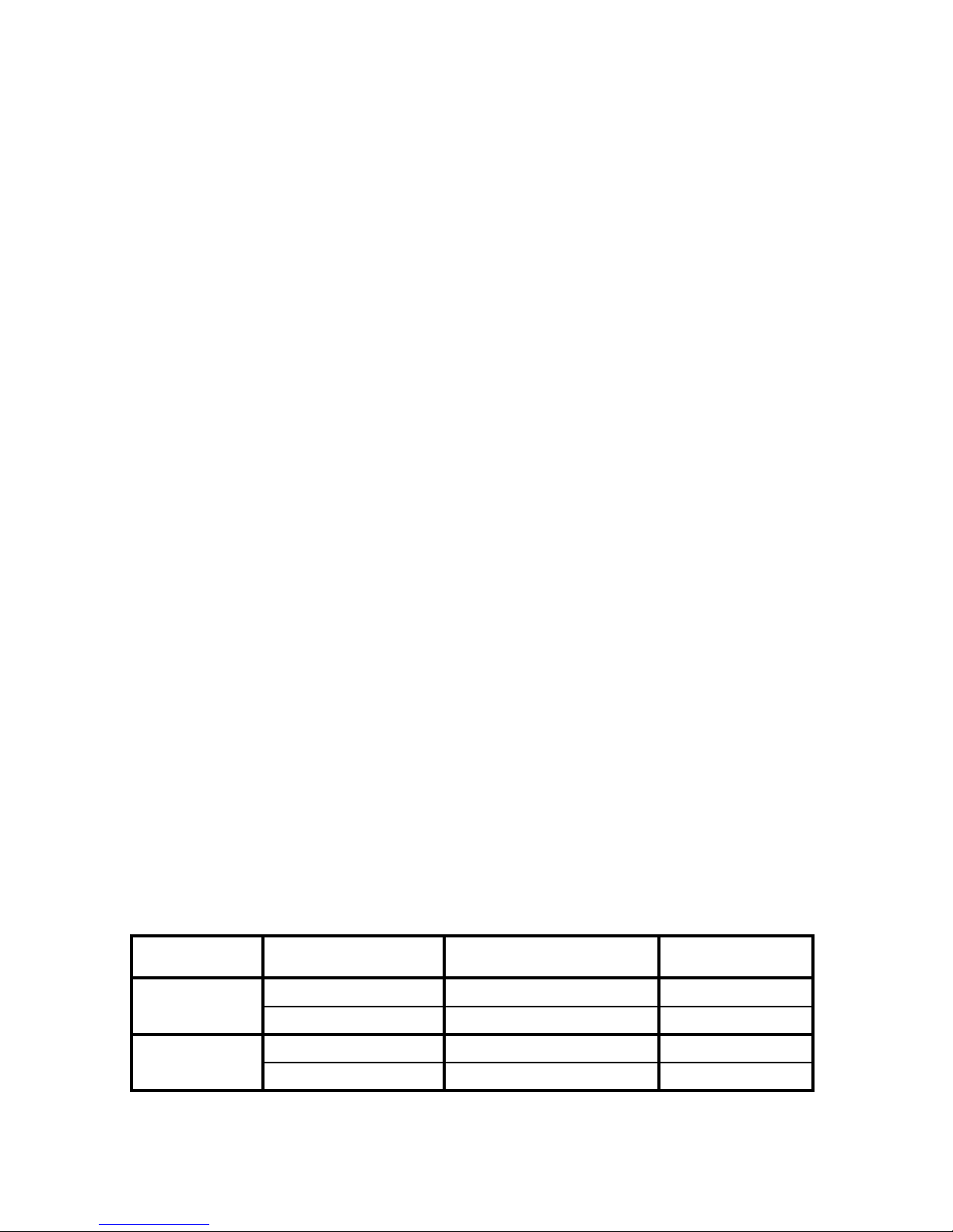
Table 4: Wiring Diagrams and Heat Anticipator Settings
Ignition Type Circulation Method
Continuous
(Standing Pilot)
Electronic
If system tends to overheat above thermostat's temperature setting, reduce heat anticipator setting by
0.1 or 0.2 amps. If system tends to shortcycle without reaching desired room temperature, increase heat
anticipator setting by 0.1 or 0.2 amps.
Intermittent 0.6 11
Constant/Gravity 1.0 14
Intermittent 0.6 12
Constant/Gravity 1.0 15
Thermostat Heat Anticipator
Setting [Amps]
Wiring
Diagram Figure
11
Page 12
Heat Anticipator in Thermostat should be set to match
the requirements of the control to which it is connected.
See Table 4. If system tends to overheat above the
thermostat's temperature setting, reduce heat anticipator
setting by .1 or .2 amps. If system tends to short cycle
without reaching desired room temperature, increase
heat anticipator setting by .1 or .2 amps.
16. INSTALL ELECTRIC WIRING in accordance with
National Electric Code or the Canadian Electrical Code
and local regulations. See Figures 11 through 16 for
applicable wiring diagram. A separate electrical circuit
must be run from the main electrical service with an
over-current device/disconnect in the circuit. A service
switch is recommended and may be required by some
local jurisdictions. When installed, the boiler must be
electrically grounded in accordance with local codes or,
in the absence of local codes, with the National
Electrical Code, ANSI/NFPA 70, and/or the CSA C22.1
Electrical Code, if an external electrical source is
utilized.
For zone valve wiring, a separate 24V transformer is
required rather than attempting to use the boiler
mounted control. Consult zone valve manufacturer for
assistance.
17. VENT DAMPER SEQUENCE OF OPERATION.
See Figure 9.
A. The Vent Damper is continuously powered at
Terminal 1.
B. When there is a call for heat, the damper relay coil is
energized through Terminal 5 if all limits ahead of
the damper are satised.
C. The relay coil closes contacts which energize the
damper motor, causing the damper to open.
D. When the damper blade reaches the fully open
position, power is sent back to the ignition circuit
through Terminal 2 and the damper motor is de-
energized.
E. When the call for heat is satised, the damper relay
coil is de-energized - closing contacts which
energize the damper motor. This causes the damper
to close. When the damper blade reaches the fully
closed position, the damper motor is de-energized.
POWER FAILURE - The damper blade will stop in
the position it was in when power failed.
(Combustion can never take place unless the damper
blade is in the fully open position.)
Figure 9: Vent Damper Schematic Wiring Diagram
This boiler contains controls which may cause the boiler to shut down and not restart without service. If
damage due to frozen pipes is a possibility, the heating system should not be left unattended in cold weather; or appropriate safeguards and alarms should be installed on the heating system to prevent damage if
the boiler is inoperative.
Avoid operating this boiler in an environment where saw dust, loose insulation bers, dry wall dust, etc.
are present. If boiler is operated under these conditions, the burner interior and ports must be cleaned and
inspected daily to insure proper operation.
12
CAUTION
CAUTION
Page 13
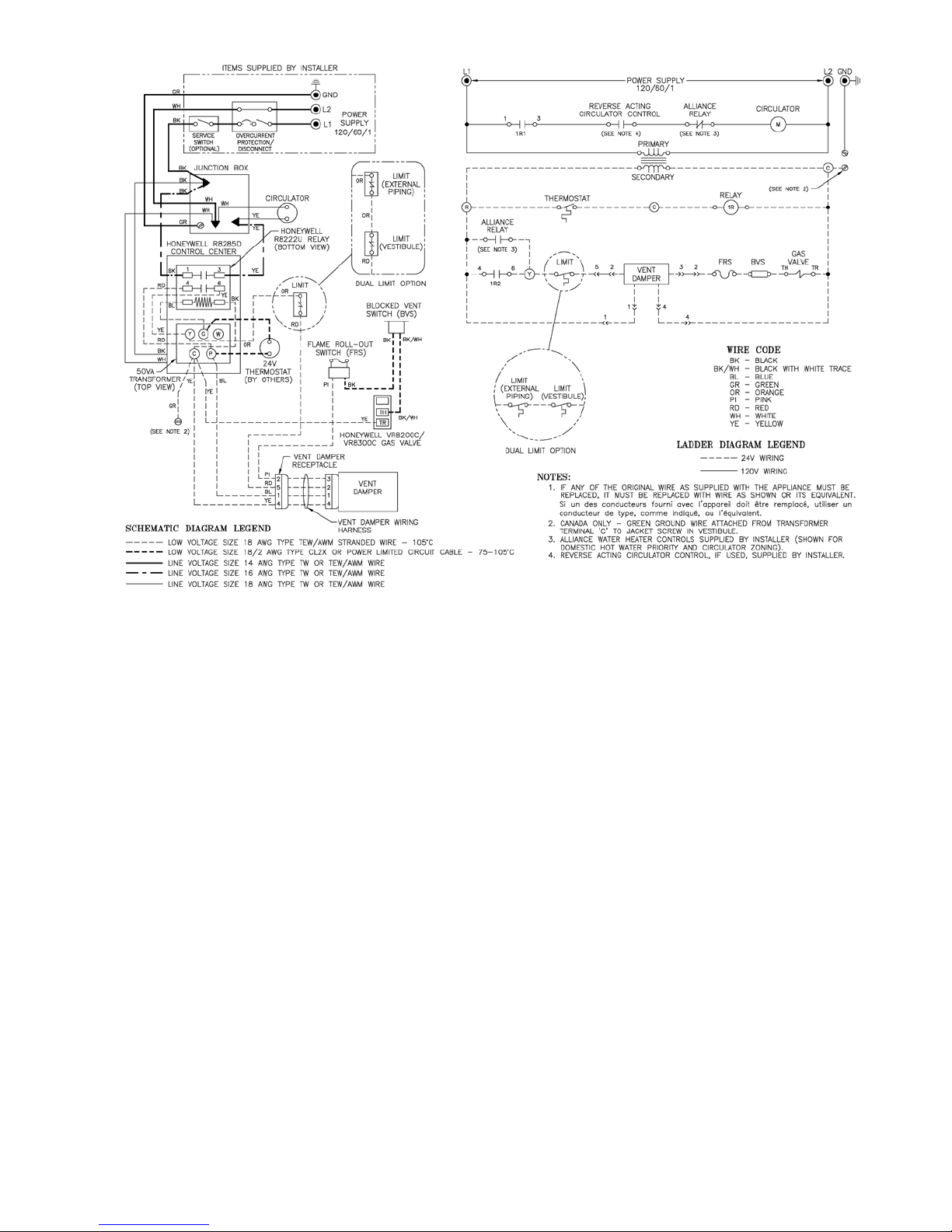
Figure 11: Wiring Diagram, 24 Volt Standing Pilot and Intermittent Circulation
SEQUENCE OF OPERATION
Normal Operation
1. When the thermostat call for heat, the vent damper
will open (see paragraphs 17A through 17D). The
circulator is started through a relay and at the same
time the gas valve is energized allowing main gas
ow and ignition of main burners.
2. Where condensation of ue gas is encountered in
boiler ues a reverse acting circulator control should
be installed to stop the circulator before the boiler
water temperature drops to that which ue gas
condensation may occur.
3. After the thermostat is satised the main valve will
close and main burner ames will be extinguished.
The vent damper will close (see paragraph 17E).
SAFETY SHUTDOWN
1. High Limit Switch
In the event excessive boiler water temperature is
developed the high limit switch will open
interrupting power to the gas valve. The main
burners will be extinguished immediately, and the
vent damper will close at the same time, but the
circulator will continue to operated. Normal
operation will be resumed when the boiler water
temperature drops to a point where the high limit
switch closes.
2. Blocked Vent Switch
In the event excessive blockage in the vent system is
developed the blocked vent switch will open
interrupting power to the gas valve. The main
burners will be extinguished immediately, the
circulator will continue to operate, and the vent
damper will remain open until the thermostat is
turned off. The source of blockage must be
corrected by trained and skilled personnel from a
qualied service agency before resetting switch.
3. Flame Rollout Switch
In the event excessive blockage in the boiler section
ue passageways is developed the ame rollout
switch will open interrupting power to the gas valve.
The main burners will be extinguished immediately,
the circulator will continue to operate and the vent
damper will remain open until the thermostat is
turned off. If the ame rollout switch is activated do
not attempt to place the boiler in operation. The
source of blockage must be corrected and the ame
rollout switch replaced by trained and skilled
personnel from a qualied service agency.
4. Pilot
The thermocouple proves pilot ame and in the
absence of such within 45-90 seconds causes the
combination gas valve, which is equipped with a
100% shut-off provision, to be de-energized, thus,
preventing main gas or pilot gas ow.
13
Page 14
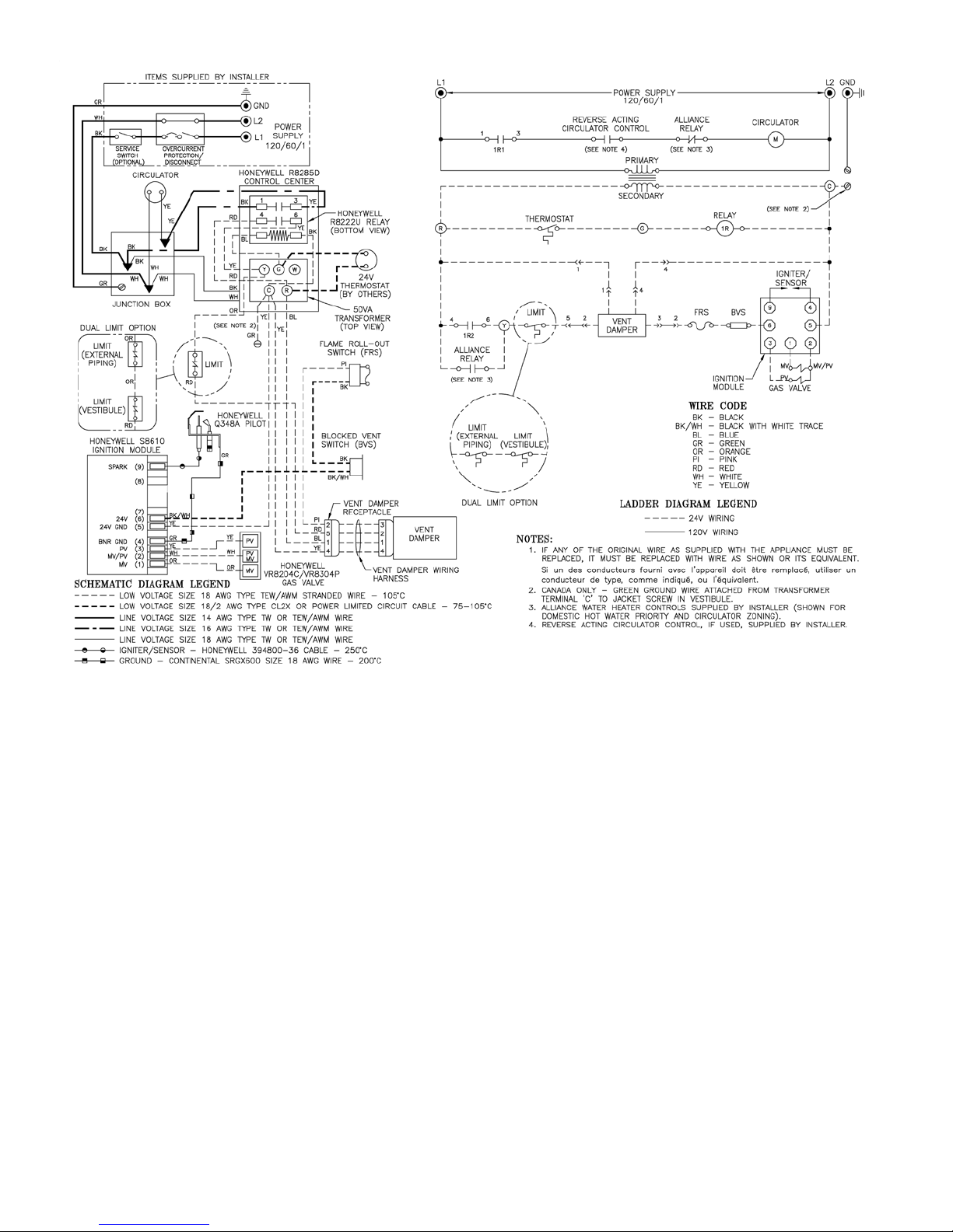
Figure 12: Wiring Diagram, Electronic Ignition (EI), Intermittent Circulation
SEQUENCE OF OPERATION
NORMAL OPERATION
1. When the thermostat calls for heat, the relay is
energized. The circulator starts and the vent damper
opens (see Paragraphs 17A through 17D). When the
damper blade reaches the fully open position, the
ignition module is energized opening the pilot valve
and energizing the igniter to ignite the pilot burner.
2. Sensor proves presence of pilot ame. Main valve
opens to ignite main burners.
3. The burners and circulator will operate
simultaneously until the thermostat is satised.
4. After thermostat is satised, ignition module is deenergized, extinguishing pilot and main ame. Vent
damper closes (see paragraph 17E).
SAFETY SHUTDOWN
1. Limit: Automatically interrupts main burner
operation when water temperature exceeds set point.
Maximum allowable temperature is 250°F. Normal
operation resumes when water temperature falls
below set point.
2. Blocked Vent Switch: Automatically interrupts
main burner operation when excessive vent system
blockage occurs. Control is a multiple use device. If
blocked vent switch is activated do not attempt to
place boiler in operation. Correct source of blockage
and reset blocked vent switch.
3. Flame Roll-out Switch: Automatically interrupts
boiler operation when ames or excessive heat are
present in vestibule. Control is single use device. If
ame roll-out switch is activated do not attempt to
place boiler in operation. Correct source of blockage
and replace ame roll-out switch.
4. Igniter/Sensor: senses pilot ame and causes
ignition module to turn off main burner and pilot
burner gas ow should pilot burner ame
extinguish. Five to six minutes after shutdown,
ignition module restarts ignition sequence.
5. For Electronic Ignition Trouble Shooting Guide, see
Page 25 of this manual.
14
Page 15
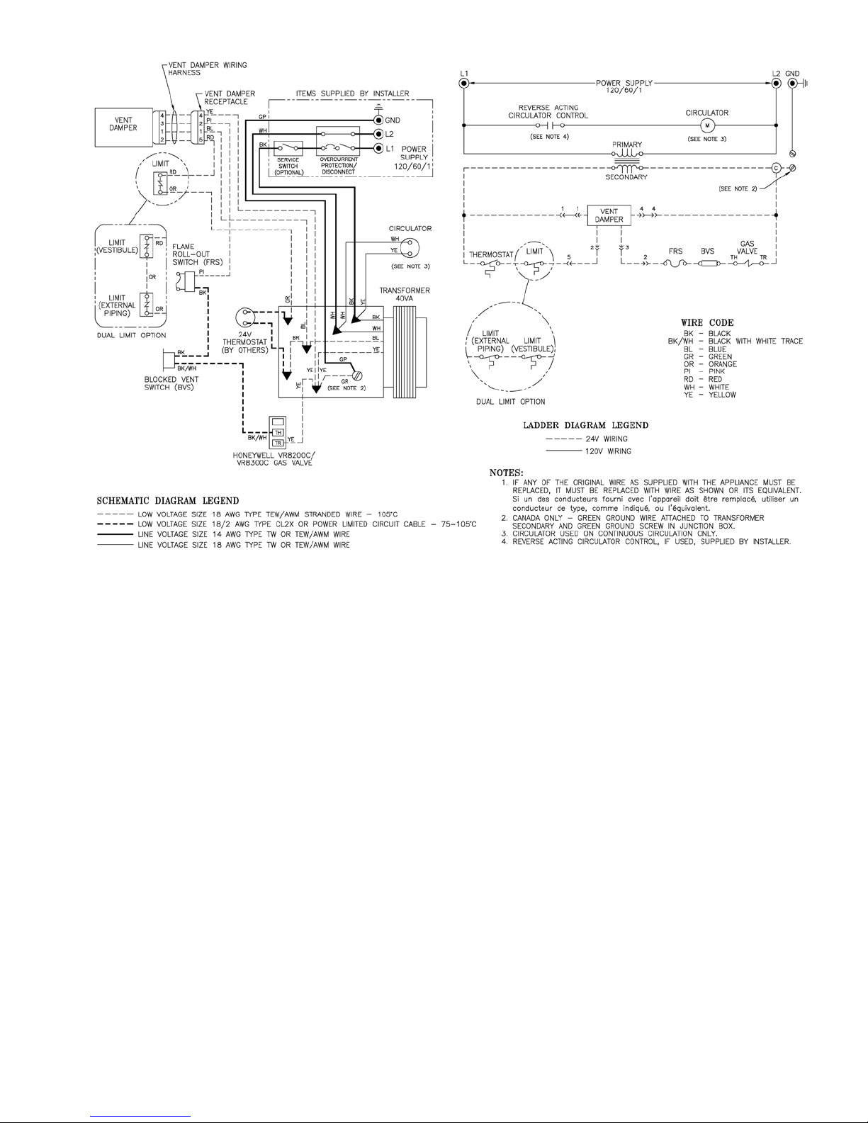
Figure 13: Wiring Diagram, 24 Volt Standing Pilot with Continuous or Gravity Circulation
SEQUENCE OF OPERATION
NORMAL OPERATION
1. When the thermostat call for heat, the vent damper
will open (see paragraphs 17A through 17D). The
gas valve is energized allowing main gas to ow and
operation of the main burners.
2. Where condensation of ue gas is encountered in
boiler ues a reverse acting circulator control should
be installed to stop the circulator before the boiler
water temperature drops to that which ue gas
condensation may occur.
3. After the thermostat is satised the main valve will
close and main burner ames will be extinguished.
The vent damper will close (see paragraph 17E). If
the boiler is so equipped, circulator will continue to
run.
SAFETY SHUTDOWN
1. High Limit Switch: In the event excessive boiler
water temperature is developed the high limit switch
will open interrupting power to the gas valve. The
main burners will be extinguished immediately.
Normal operation will be resumed when the boiler
water temperature drops to a point where the high
limit switch closes.
2. Blocked Vent Switch: In the event excessive
blockage in the vent system is developed the
blocked vent switch will open interrupting power to
the gas valve. The main burners will be extinguished
immediately and the vent damper will remain open
until the thermostat is turned off. The source of
blockage must be corrected by trained and skilled
personnel from a qualied service agency before
resetting switch.
3. Flame Rollout Switch: In the event excessive
blockage in the boiler section ue passageways is
developed the ame rollout switch will open
interrupting power to the gas valve. The main
burners will be extinguished immediately and the
vent damper will remain open until the thermostat is
turned off. If the ame rollout switch is activated do
not attempt to place the boiler in operation. The
source of the blockage must be corrected and the
ame rollout switch replaced by trained and skilled
personnel from a qualied service agency.
4. Pilot: The thermocouple proves pilot ame and in
the absence of such within 45-90 seconds causes the
combination gas valve, which is equipped with a
100% shut-off provision, to be de-energized, thus,
preventing main gas or pilot gas ow.
15
Page 16

Figure 14: Wiring Diagram, Electronic Ignition (EI), Continuous or Gravity Circulation
SEQUENCE OF OPERATION
NORMAL OPERATION
1. When the thermostat calls for heat the vent damper
opens (see Paragraphs 17A through 17D). When the
damper blade reaches the fully open position, the
ignition module is energized opening the pilot valve
and energizing the igniter to ignite the pilot burner.
2. Sensor proves presence of pilot ame. Main valve
opens to ignite main burners.
3. The burners will operate until the thermostat is
satised.
4. When thermostat is satised, ignition module is deenergized, extinguishing pilot and main ame. If
boiler is equipped with circulator, circulator will
continue to run. Vent damper closes (see Para-graph
17E).
SAFETY SHUTDOWN
1. Limit: Automatically interrupts main burner
operation when water temperature exceeds set point.
Maximum allowable temperature is 250°F. Normal
operation resumes when water temperature falls
below set point.
2. Blocked Vent Switch: Automatically interrupts
main burner operation when excessive vent system
blockage occurs. Control is a multiple use device. If
blocked vent switch is activated do not attempt to
place boiler in operation. Correct source of blockage
and reset blocked vent switch.
3. Flame Roll-out Switch: Automatically interrupts
boiler operation when ames or excessive heat are
present in vestibule. Control is single use device. If
ame roll-out switch is activated do not attempt to
place boiler in operation. Correct source of blockage
and replace ame roll-out switch.
4. Igniter/Sensor: senses pilot ame and causes
ignition module to turn off main burner and pilot
burner gas ow should pilot burner ame
extinguish. Five to six minutes after shutdown,
ignition module restarts ignition sequence.
5. For Electronic Ignition Trouble Shooting Guide, see
Page 25 of this manual.
16
Page 17

Figure 15: Wiring Schematic, Zone Valves
Figure 16: Wiring Schematic, Zone Circulators
17
Page 18

II. Operating Instructions
Safe lighting and other performance criteria were met with the gas manifold and control assembly provided on the boiler when the
boiler underwent tests specied in American National Standard for Gas-Fired Low-Pressure Steam and Hot Water Boilers, ANSI
Z21.13b-1994.
1. MAIN BURNER CHECK - Check main burners to
see that they were not dislodged during shipment. Rear
of burners should be in the slots in the rear of burner
tray and the front of the burners should be seated
completely on the orices.
2. INITIAL START -
A. FILL ENTIRE HEATING SYSTEM WITH
WATER and vent air from system. Use the
following procedure on a Series Loop System
equipped with zone valves. (See Figure 3).
1. Close isolation valve in boiler supply piping.
2. Isolate all circuits by closing zone valves or
balancing valves.
3. Attach a hose to hose bib located just below
isolation valve in boiler supply piping. (Note -
Terminate hose in ve gallon bucket at a suitable
oor drain or outdoor area).
4. Starting with one circuit, open zone valve.
5. Open hose bib.
6. Open ll valve (Make-up water line should be
located directly above isolation valve in boiler
supply piping).
7. Allow water to overow from bucket until
discharge from hose is bubble free for 30
seconds.
8. Open zone valve to the second zone to be purged,
then close the rst. Repeat this step until all
zones have been purged, but always have one
zone open. At completion, open all zone valves.
9. Close hose bib, continue lling the system until
the pressure gauge reads 12 psi. Close ll valve.
(Note - If make-up water line is equipped with
pressure reducing valve, system will
automatically ll to 12 psi. Leave globe valve
open).
10. Open isolation valve in boiler supply piping.
11. Remove hose from hose bib.
B. Turn ROOM THERMOSTAT to lowest setting.
C. Be sure that gas to pilot and main burners has been
off for at least ve minutes and vent damper (if
used) has been in the open position.
D. Turn "OFF" the electric switch serving boiler.
E. Open valve on main gas line at meter.
F. PURGE AIR FROM GAS PIPING. This
procedure will vary with equipment furnished but in
all cases adequate ventilation must be provided
and no smoking or open ame permitted. To
determine which of the procedures outlined in
succeeding paragraphs is applicable, match sufx of
Figure 17: Schematic Pilot and Gas Piping
Continuous Ignition (Standing Pilot)
Figure 18: Schematic Pilot and Gas Piping
Electronic Ignition (EI)
boiler model found on Rating Label with paragraph
heading:
1. Standing Pilot Models (Sufx C):
a. Keep electric switch "OFF".
b. Open Manual Shut-off Valve upstream of
Combination Gas Valve.
c. Disconnect Pilot Tubing at gas valve (Purge
must not be into combustion chamber).
d. Turn Main Gas Knob on Combination Gas
Valve to "Pilot" Position. Depress and hold
in this position until purging is complete.
Turn Main Gas Knob to "off" position.
18
Page 19

Figure 19: Top View of VR Gas Valves
Figure 20: Operating Instructions, VR8204 and VR8304 Gas Valves
19
Page 20

e. Reconnect pilot tubing and check pipe and
ttings from meter to combination Gas
Valve for leaks using soap solution or other
approved method.
2. Electronic Ignition Models (Sufx I):
a. Turn "ON" electric switch serving boiler.
b. Open Manual Shut-off Valve upstream of
Combination Gas Valve.
c. Loosen or remove Inlet Pressure Tap Plug in
Combination Gas Valve and when purging is
complete, tighten or replace plug. See Figure
19.
d. Check pipe and ttings from meter to
Combination Gas Valve using soap solution
or other approved methods.
CAUTION
Figure 21: LED Locations
e. Test gas piping and connections between
Combination Gas Valve and manifold,
orices, and pilot piping for leaks after
boiler is operating. Use soap solution or
other approved method.
3. INSTRUCTIONS TO PUT THE BOILER IN
OPERATION.
A. See Figure 20 for electronic ignition (EI).
Electronic Ignition Modules with LED indicators.
Table 5 cross-references the ignition module
terminal designations to the ignition terminal
Table 5: Ignition Module Terminal Cross Reference
Ignition Module
Terminal Designation
MV 1
MV/PV 2
PV 3
GND 4
24V (GND) 5
numbers in the wiring ladder diagrams. The yellow
LED indicates the status of the ame, see Table 6.
The green LED indicates the status of the system,
see Table 7. See Figure 21 for LED locations. See
24V 6
SPARK 9
Figure 28 for Troubleshooting Guide.
Table 6: Yellow LED Flame Codes
Yellow LED Flash
a
Code
Indicates Recommended Service Action
Heartbeat Normal Flame Signal N/A
Weak Flame Signal -
System will operate reliably but ame signal is less than
2
1
desired.
Note: This indication may ash temporarily during or
shortly after lightoff on some applications.
Marginal Flame Signal (less than 1.1 µA) System may not operate reliably over time. Service call
recommended.
Note: This indication may ash temporarily during or
shortly after lightoff on some applications.
Perform routine maintenance to
assure optimum ame signal.
Check gas supply, pilot burner, ame sense
wiring, contamination of ame rod, burner
ground connection.
Wiring Ladder Diagram
Terminal Number
No Flame or Flame Signal -
OFF
a
Flash Code Descriptions
- Heartbeat: Constant ½ second bright, ½ second dim cycles.
- The ash code number signies that the LED ashes X times at 2Hz, remains off for two seconds, and then repeats sequence.
below minimum threshold for system
operation.
20
N/A
Page 21

Table 7: Green LED Status Codes
Green LED
Flash Code
(X + Y)
Flash Fast
Heartbeat Normal operation N/A None
a
Flash Code Descriptions:
a
OFF No “Call for Heat” N/A None
Startup - Flame sense
calibration
5 minute Retry Delay-
2
Pilot ame not detected
during trial for ignition
3
4
7
8
Recycle- Flame failed
during run
Flame sensed out of
sequence
Flame sense leakage to
ground
Low secondary voltage
supply- (below 15.5 Vac)
5 minute Retry Delay-
6 + 2
On every third retry on
same “Call for Heat”
On every 6th ame
6 + 3
failure during run on the
same “Call for Heat”
Flame sensed out of
6 + 4
sequence- longer than
10 seconds
Soft lockout due to error
ON
detected during self
check sequences
- Flash Fast: rapid blinking
- Heartbeat: Constant ½ second bright, ½ second dim cycles.
- A single ash code number signies that the LED ashes X times at 2Hz, remains off for two seconds, and then
repeats the sequence.
- X + Y ash codes signify that the LED ashes X times at 2Hz, remains off for two seconds, ashes Y times at 2
Hz, remains off for three seconds, and then repeats the sequence.
Indicates Next System Action Recommended Service Action
N/A None
If system fails to light on next trial
for ignition check gas supply, pilot
Initiate new trial for ignition after retry
delay completed.
Initiate new trial for ignition. Flash
code will remain through the ignition
trial until ame is proved.
If situation self corrects within 10
seconds, control returns to normal
sequence. If ame out of sequence remains longer than 10 seconds, control
goes to Flash code 6+4 (see below)
Control remains in wait mode. When
the fault corrects, control resumes normal operation after a one minute delay.
Control remains in wait mode. When
the fault corrects, control resumes normal operation after one minute delay.
Initiate new trial for ignition after retry
delay completed.
5 minute retry delay, then initiate new
trial for ignition.
Control waits until ame is no longer
sensed and then goes to soft lockout.
Flash code continues. Control auto
resets from soft lockout after one hour.
Control auto resets from soft lockout
after one hour.
burner, spark and ame sense wir-
ing, ame rod contamination or out
of position, burner ground connec-
tion.
If system fails to light on next trial
for ignition check gas supply, pilot
burner, ame sense wiring, ame
rod contamination, burner ground
connection.
Check for pilot ame. Replace gas
valve if pilot ame present. If no
pilot ame, cycle “Call for Heat.” If
error repeats, replace control.
Check ame sense lead wire for
damage or shorting. Check that
ame rod is in proper position.
Check ame rod ceramic for cracks,
damage or tracking.
Check transformer and AC line for
proper input voltage to the control.
Check with full system load on the
transformer.
Check gas supply, pilot burner, spark
and ame sense wiring, ame rod
contamination or out of position,
burner ground connection.
Check gas supply, pilot burner, ame
sense wiring, contamination of ame
rod, burner ground connection.
Check for pilot ame. Replace gas
valve if pilot ame present. If no
pilot ame, cycle “Call for Heat.” If
error repeats, replace control.
Reset by cycling “Call for Heat.” If
error repeats, replace the control
21
Page 22

22
Figure 22: Lighting Instructions
Page 23

B. See Figure 22 for continuous ignition system
(standing pilot).
4. CHECK GAS INPUT RATE TO BOILER
NOTICE
USA boilers built for installation at altitudes greater
than 2,000 feet above sea level have been specially
oriced to reduce gas input rate 4 percent per 1,000 feet
above sea level per the National Fuel Gas Code, NFPA
54/ANSI Z223.1, Section 8.1.2 and Appendix F.
Canadian boilers' orice sizing is indicated on the rating
label. High altitude boiler models are identiable by
the fourth digit after the dash in the model number. 2:
0-2000', 4 or 5: above 2000'.
A. Input Rate and Maximum Inlet Pressure shown on
Rating Label must not be exceeded. Inlet pressure
must not be lower than minimum inlet pressure
shown on Rating Label.
B. All Rate checks and all adjustments are to be made
while boiler is ring - all other appliances connected
to the same meter as the boiler must be off.
C. With boiler off, water Manometer or water column
gauge should be connected to a shut-off valve
installed in the 1/8" outlet pressure tap in the gas
valve (see Figure 19). By installing gas valve
upstream of manometer, gas pressure can be
introduced gradually - without shut-off valve, surge
of pressure when boiler is turned on, could blow
liquid out of manometer. Replace plug in gas valve
when rate check is nished.
D. LP Gas Input:
Adjust Regulator on Gas Valve so that manifold
pressure is 10 inches water column. Turning
Regulator Adjusting Screw Clockwise increases
pressure. Counterclockwise rotation decreases
pressure.
more accurate check on input is necessary see
(2) below.
For minor input changes readjust Regulator Gas
Valve to increase or decrease manifold pressure
to obtain corresponding increase or decrease in
gas input. If it is necessary to increase manifold
pressure more than 0.3" of water to obtain rated
input, remove orices and drill one size larger.
Reinstall and recheck input rate.
2. Additional Check on Input - Since input is a
function of heating value, specic gravity, and
volume of gas ow contact your utility for the
rst two items in order to utilize the formula
below. The gas meter should then be clocked for
three (3) minutes with stop watch and
substituting the appropriate values in the formula
below, determine what the gas ow should be in
this 3 minute period to give the input shown on
the Rating Label:
Gas Input
(cu. ft.)
per 3 min. Value X from
=
Heating Multiplier
of Gas Table 3
(Btu / cu. ft.
Btuh Input
5. MAIN BURNER FLAMES should have a clearly
dened inner cone (see Figure 23 or 24) with no yellow
tipping. Orange-yellow streaks caused by dust should
not be confused with true yellow tipping.
Figure 23: 40mm Main Burner Flame
E. Natural Gas Input
1. Appx. Input - Adjust regulator on Gas Valve so
that manifold pressure is three and a half (3½)
inches water column. Turning Regulator
Adjusting Screw Clockwise increases pressure,
Counterclockwise rotation decreases pressure. If
Figure 24: 1 Inch Main Burner Flame
The main burners in this boiler will not operate cleanly
or efciently if they are contaminated with dirt and/or
construction dust. Burners should be cleaned and the
combustion chamber vacuumed following instructions
in Section IV. Service.
6. CHECK PILOT BURNER FLAME.
A. Continuous Ignition (Standing Pilot)
LP gas Models 202 and 202X. See Figure 25.
Natural gas Models 202 through 206 and 207 with
1" diameter burners. See Figure 25.
23
Page 24

Figure 25: Typical Pilot Flame, Honeywell Q350
The pilot produces a single ame. The ame should
be steady, medium hard blue enveloping 3/8 to a 1/2
inch of thermocouple.
B. Continuous Ignition (Standing Pilot)
Natural gas Models 207 with 40mm (1-9/16")
diameter burners and 208 through 210.
See Figure 26.
LP gas Models 203 through 210. See Figure 26.
The pilot produces three (3) ames. The center
ame should be steady, medium hard blue
enveloping 3/8 to a 1/2 inch of thermocouple.
Figure 26: Typical Pilot Flame, Honeywell Q327
C. Electronic Ignition (EI), see Figure 27.
The pilot produces three (3) ames. The center
ame should be steady, medium hard blue
enveloping 3/8 to a ½ inch of sensing probe.
Figure 27: Typical Pilot Flame, Honeywell Q348A
7. CHECK THERMOSTAT OPERATION. Raise and
lower temperature setting as required to start and stop
burners.
8. CHECK HIGH LIMIT CONTROL. Jumper
Thermostat Terminals or Thermostat connections in
Limit Control. Allow burners to operate until shutdown
by limit. REMOVE JUMPER.
9. CHECK DAMPER OPERATION. Vent Damper must
be open when boiler is running. Le registre doit être
ouvert lorsque le brûleur principal de l’appareil
fonctionne. Start boiler, refer to instructions on damper
to determine if damper is in the full open position.
10. CHECK IGNITION SYSTEM SAFETY SHUT-OFF
DEVICE.
A. 24 volt-loosen thermocouple at gas valve.
B. Electronic Ignition - Remove pilot lead wires from
gas valve.
If burners do not shut down determine cause of
malfunction. Replace necessary items and check
operation.
11. COMBUSTION CHAMBER BURN-OFF
A. The mineral wool combustion chamber panels may
contain a cornstarch based binder that must be
burned out at installation to prevent odors during
subsequent boiler operation.
B. Ventilate the boiler room, set the high limit to its
maximum setting, set the thermostat to call for heat.
Allow the boiler to re for at least an hour or until
the odor from the cornstarch has dissipated.
C. Return the high limit and thermostat to their desired
settings.
24
Page 25

III. Trouble Shooting
Honeywell Electronic Ignition Troubleshooting Guide
Figure 28: Troubleshooting Guide, Honeywell Electronic Ignition (EI)
25
Page 26

IV. Service
1. Inspection should be conducted annually. Service as
frequently as specied in paragraphs below. While
service or maintenance is being done, Electrical Power
and all Gas Supply to the Boiler must be "off".
CAUTION
Label all wires prior to disconnection when
servicing controls. Wiring errors can cause
improper and dangerous operation. Verify
proper operation after servicing.
ATTENTION. Au moment de l’entretien des
commandes, étiquetez tous les ls avant
de les débrancher. Les erreurs de câblage
peuvent nuire au bon fonctionnement et être
dangereuses.
S’assurer que l’appareil fonctionne
adéquatement une fois l’entretien terminé.
2. VENT SYSTEM. Vent system (see Figure 8 for typical
installation) should be checked annually for:
A. Obstructions.
B. Accumulations of soot.
C. Deterioration of vent pipe or vent accessories due to
condensation or other reasons.
D. Proper support - no sags, particularly in horizontal
runs.
E. Tightness of joints.
F. Proper vent damper operation - see Section II
Operating Instructions, paragraph 9.
G. Remove all accumulations of soot with wire brush
and vacuum, see Figure 29. Remove all
obstructions. Replace all deteriorated parts and
support properly. Seal all joints.
3. CLEANING BOILER FLUES, see Figure 29.
Flue passageways in the boiler sections should be
checked annually for any blockage or accumulation of
soot. To obtain access to ueways:
A. Remove vent pipe, damper (if boiler is so equipped),
blocked vent switch, and draft hood.
B. Remove sheet metal screws securing Jacket Top
Panel, lift panel and rotate about relief valve piping
until top of boiler is exposed.
C. Remove bolts securing Canopy to Boiler Sections.
Remove Canopy - ueways are now exposed.
D. Models with ue gas bafes only: Remove bafes
by lifting out of ueways.
Using ashlight, examine all ue passageways. If
passageways are free of soot and obstruction,
replace canopy (and ue gas bafes, if applicable),
and seal.
26
Reinstall Jacket Top Panel, draft hood, blocked vent
switch, damper (if boiler is so equipped), and vent
pipe.
If the ue passageways need cleaning, remove
burners as described in paragraph 4 below. Using
long handle wire or bristle ue brush and vacuum,
brush ueways thoroughly from top of boiler as
illustrated in Figure 29. Replace canopy and seal
with boiler putty. Reinstall Jacket Top Panel, draft
hood, blocked vent switch, damper (if boiler is so
equipped), and vent pipe.
NOTICE
4. BURNERS AND FIREBOX SHOULD BE CLEANED
ANNUALLY, AND IF NECESSARY ADJUSTED
ONCE A YEAR BY A QUALIFIED SERVICE
AGENCY.
A. TO REMOVE BURNERS FOR CLEANING,
CHANGING ORIFICE PLUGS, OR REPAIRS.
1. Remove the jacket front panel.
2. Disconnect pilot tubing at the gas valve. See
Figure 17.
3. Disconnect thermocouple (standing pilot) or pilot
lead wires (electronic ignition) at the gas valve.
4. 40mm burners only. Remove injection shield
assembly, where used. See Figure 30.
5. Remove wires to ame roll-out switch.
6. Remove the burner access panel.
7. Mark the location of the pilot main burner on the
manifold if the marking on manifold is missing
or obliterated.
Figure 29: Cleaning of Vent System
and Boiler Flues
Page 27

8. Hold burner at throat. Lift front of burner to
clear orice. Burner which holds pilot can only
be removed by lifting the burner adjacent to its
right rst.
1" Burner
40mm Burner
Figure 30: Burner Cleaning and Installation
9. Brush top of burners with a soft bristle brush, see
Figure 30. Vacuum burners. Check orices to see
that drilled passageways are free of lint or dirt.
10. Vacuum tip of Pilot Burner.
B. CLEAN FIREBOX by vacuuming. Exercise care
not to disturb insulation inside the base.
C. INSTALL BURNERS by reversing procedure used
to remove burners. Make sure burner with pilot
assembly is in same location as original installation
- see Table 8.
Check burners to see that they are located properly
in slot at rear of burner tray, see Figure 30.
Reinstall injection shield assembly (40mm burners
only, where used) and burner access panel.
Reconnect ame roll-out switch wires, pilot gas
supply, thermocouple lead or pilot lead.
D. CHECK MAIN BURNER and PILOT FLAMES,
see procedure Section II Operating Instructions,
paragraphs 5 and 6.
5. CHECK ALL CONTROL AND DAMPER
OPERATION ANNUALLY see procedure in Section II
Operating Instructions, paragraphs 7 through 10.
6. REMOVAL OR REPLACEMENT OF PILOT
ASSEMBLY OR PILOT ASSEMBLY PARTS
If pilot assembly, thermocouple or pilot orice need
replacing, remove main burner with pilot using
procedure described in paragraph 4.
A. To replace orice:
1. Disconnect pilot tubing. The Honeywell Q350
pilot orices are insert type retained by the
compression tting. The Honeywell Q327 and
Q348A pilot orices are spud type screwed into
pilot burner. Replace with desired orice. See
Key No. 5B.
2. Reconnect pilot tubing and check for leaks.
B. To replace Honeywell Q309A thermocouple in
Q327 or Q350 pilot:
1. Loosen attachment nut securing thermocouple to
barrel of pilot burner. Disconnect other end at
combination gas valve.
2. Remove thermocouple and replace with equal.
C. To replace complete pilot assembly.
1. Remove machine screws holding pilot burner to
pilot bracket.
2. Disconnect pilot piping.
3. Disconnect all other leads to pilot.
4. Select pilot assembly with identical model
number, reconnect leads and pilot tubing resecure to pilot bracket.
D. To adjust or check spark gap between electrode and
hood on Honeywell Q348A pilot.
1. Use round wire gauge to check spark gap.
2. Spark gap should be 1/8 inch for optimum
performance.
E. Reinstall main burner following procedure described
in paragraph 4.
7. LUBRICATION
There are no parts requiring lubrication on the part of
the service technician or the User. Circulator bearings
are water lubricated.
Table 8: Pilot Burner Location
Boiler
Model
202 1 1 1 & 2 ---
202X 1 1 1 & 2 1 & 2
203 1 1 1 & 2 1 & 2
204 2 2 2 & 3 2 & 3
205 3 2 3 & 4 2 & 3
206 4 3 4 & 5 3 & 4
207 6 3 6 & 7 3 & 4
208 7 4 7 & 8 4 & 5
209 8 4 8 & 9 4 & 5
210 9 5 9 & 10 5 & 6
* Main burners numbered left to right as viewed from
front of boiler.
Main Burner with
Pilot Bracket *
1 Inch 40mm 1 Inch 40mm
Pilot Burner Located
Between Main
Burners *
27
Page 28

Important Product Safety Information
Refractory Ceramic Fiber Product
Warning:
The Repair Parts list designates parts that contain refractory ceramic fibers
(RCF). RCF has been classified as a possible human carcinogen. When
exposed to temperatures about 1805°F, such as during direct flame contact,
RCF changes into crystalline silica, a known carcinogen. When disturbed as a
result of servicing or repair, these substances become airborne and, if inhaled,
may be hazardous to your health.
AVOID Breathing Fiber Particulates and Dust
Precautionary Measures:
Do not remove or replace RCF parts or attempt any service or repair work
involving RCF without wearing the following protective gear:
1. A National Institute for Occupational Safety and Health (NIOSH)
approved respirator
2. Long sleeved, loose fitting clothing
3. Gloves
4. Eye Protection
• Take steps to assure adequate ventilation.
• Wash all exposed body areas gently with soap and water after contact.
• Wash work clothes separately from other laundry and rinse washing
machine after use to avoid contaminating other clothes.
• Discard used RCF components by sealing in an airtight plastic bag. RCF
and crystalline silica are not classified as hazardous wastes in the United
States and Canada.
First Aid Procedures
:
• If contact with eyes: Flush with water for at least 15 minutes. Seek
immediate medical attention if irritation persists.
• If contact with skin: Wash affected area gently with soap and water.
Seek immediate medical attention if irritation persists.
• If breathing difficulty develops: Leave the area and move to a location
with clean fresh air. Seek immediate medical attention if breathing
difficulties persist.
• Ingestion: Do not induce vomiting. Drink plenty of water. Seek
immediate medical attention.
28
Page 29

V. Repair Parts
Section Assembly and Canopy Group ............................30
Base Assembly ..................................................................32
Manifold and Main Burners
1 Inch Main Burners ..................................................
34
40mm Main Burners ..................................................36
Pilot Burner and Gas Valve
Continuous Ignition (Standing Pilot) .......................38
Electronic Ignition .....................................................40
Jacket Assembly ...............................................................41
Water Trim .......................................................................44
Controls .............................................................................46
Draft Hood and Vent Damper .........................................47
Key
Description Part No.
No.
1. Section Assembly (Intermittent and Continuous Circulation Only)
617170221 1 --- --- --- --- --- --- --- --- --617170321 --- 1 1 --- --- --- --- --- --- --617170421 --- --- --- 1 --- --- --- --- --- --617170521 --- --- --- --- 1 --- --- --- --- ---
1 Section Assembly, Complete
1. Section Assembly (Gravity Circulation Only)
1 Section Assembly, Complete
617170621 --- --- --- --- --- 1 --- --- --- --617170721 --- --- --- --- --- --- 1 --- --- --617170821 --- --- --- --- --- --- --- 1 --- --617170921 --- --- --- --- --- --- --- --- 1 --617171021 --- --- --- --- --- --- --- --- --- 1
617170231 1 --- --- --- --- --- --- --- --- --617170331 --- 1 1 --- --- --- --- --- --- --617170431 --- --- --- 1 --- --- --- --- --- --617170531 --- --- --- --- 1 --- --- --- --- --617170631 --- --- --- --- --- 1 --- --- --- --617170731 --- --- --- --- --- --- 1 --- --- --617170831 --- --- --- --- --- --- --- 1 --- --617170931 --- --- --- --- --- --- --- --- 1 --617171031 --- --- --- --- --- --- --- --- --- 1
202 202X 203 204 205 206 207 208 209 210
Quantity
29
Page 30

Key
Description Part No.
No.
2. Canopy Group
Quantity
202 202X 203 204 205 206 207 208 209 210
61117022 1 --- --- --- --- --- --- --- --- --611170300 --- 1 --- --- --- --- --- --- --- --611170302 --- --- 1 --- --- --- --- --- --- --611170402 --- --- --- 1 --- --- --- --- --- ---
Canopy Assembly (except for 206H)
2A
Canopy Assembly 206H 6111706010 --- --- --- --- --- 1 --- --- --- --2B Carriage Bolt, 1/4-20 x 1" 80860115 2 2 2 2 2 2 2 2 2 2
2C Flat Washer, 1/4" 80860603 2 2 2 2 2 2 2 2 2 2
2D Nut, Hex, 1/4-20 80860407 2 2 2 2 2 2 2 2 2 2
2E Cerafelt Sealing Strip, 1/2" x 1" x 10' 6206001 1 1 1 1 1 1 1 1 1 1
Flue Gas Bafe (*Standing Pilot 1"
Burners Only)
2F
(** LP Standing Pilot 1" Burners Only)
(*** Standing Pilot Models Only)
611170502 --- --- --- --- 1 --- --- --- --- --611170602 --- --- --- --- --- 1 --- --- --- --611170702 --- --- --- --- --- --- 1 --- --- --611170802 --- --- --- --- --- --- --- 1 --- ---
611170902 --- --- --- --- --- --- --- --- 1 ---
611171002 --- --- --- --- --- --- --- --- --- 1
71106001 1*** --- 2** 3** 4** 5** 6** 7* 8* 9*
30
Section Assembly and Canopy Group
Page 31

THIS PAGE LEFT INTENTIONALLY BLANK
31
Page 32

Base Assembly
Key
Description
No.
3. Base Assembly
Base Assembly
(Complete)
3
Available for 1 Inch
Burners Only
3A Base Tray
32
Boiler
Size
202 618600291 1
202X 618600391 1
203 618600391 1
204 618600491 1
205 618600591 1
206 618600691 1
207 618600791 1
208 618600891 1
209 618600991 1
210 618601091 1
202 718600291 1
202X 718600391 1
203 718600391 1
204 718600491 1
205 718600591 1
206 718600691 1
207 718600791 1
208 718600891 1
209 718600991 1
210 718601091 1
Part No. Qty.
Key
No.
Description
Boiler
Size
Part No. Qty.
3. Base Assembly Continued
202 718600211 1
202X 718600311 1
203 718600311 1
204 718600411 1
3B Base Wrapper
3B1 Base End Insulation All 720601 2
3B2 Base Rear Insulation
205 718600511 1
206 718600611 1
207 718600711 1
208 718600811 1
209 718600911 1
210 718601011 1
202 72060025 1
202X 72060035 1
203 72060035 1
204 72060045 1
205 72060055 1
206 72060065 1
207 72060075 1
208 72060085 1
209 72060095 1
210 72060105 1
Page 33

Key
No.
Description
Boiler
Size
Part No. Qty.
Key
No.
Description
Boiler
Size
Part No. Qty.
3. Base Assembly Continued
202X 618600341 1
Base Front Panel
3C
Assembly
202X 718600305 1
Burner Tray (1" Main
Burners)
3D
202X 71806037 1
Burner Tray
(40mm Main Burners)
202 618600241 1
203 618600341 1
204 618600441 1
205 618600541 1
206 618600641 1
207 618600741 1
208 618600841 1
209 618600941 1
210 618601041 1
202 718600205 1
203 718600305 1
204 718600405 1
205 718600505 1
206 718600605 1
207 718600705 1
208 718600805 1
209 718600905 1
210 718601005 1
202 718600206 1
203 71806037 1
204 71806047 1
205 71806057 1
206 71806067 1
3. Base Assembly Continued
3E Base Leg Assembly All 6186001 4
3E1 Base Leg All 71860021 4
3E2 Nylon Glide All 8186006 4
202 718600261 1
202X 718600361 1
203 718600361 1
204 718600461 1
3F Burner Access Panel
Cerafelt Sealing Strip,
3G
1" x 2" x 10' (Section
Assembly to Base)
Self-Tapping Screw,
3H
1/4" -20 x 1/2"
Self-Tapping Screw,
3J
5/16" -18 x 1-1/4"
Flat Washer, 5/16",
3K
USS
Hex Lock Nut,
3L
5/16 -18
205 718600561 1
206 718600661 1
207 718600761 1
208 718600861 1
209 718600961 1
210 718601061 1
All 6206002 1
202
thru
206
207
thru
210
80860700 20
80860700 21
All 80860717 4
All 80860601 4
All 80860464 4
207 71806077 1
208 718600806 1
209 718600906 1
210 718601006 1
33
Page 34

Manifold and Main Burners
(1 Inch Main Burners)
34
Page 35

Key
Description Part No.
No.
202 202X 203 204 205 206 207 208 209 210
Quantity
4. Manifold and Main Burners (1 Inch Main Burners Only)
4A Main Burner 8236099 1 2 2 4 6 8 11 13 15 17
4B Main Burner with Pilot Bracket ----- See Table Below
82260023 1 --- --- --- --- --- --- --- --- --82260033 --- 1 1 --- --- --- --- --- --- --82260043 --- --- --- 1 --- --- --- --- --- --82260053 --- --- --- --- 1 --- --- --- --- ---
4C Manifold
4D Main Burner Orice ----- See Table Below
Screw, Machine, Slotted Round Head,
#10 -32 x 3/16" (Standing Pilot)
4E
Screw, Machine, Philips Head
w/Captive Lockwasher, #10 -32 x 1/4"
(Electronic Ignition)
Screw, Self Tapping, Philips Pan
4F
Head, 1/4 - 20 x 1/2"
82260063 --- --- --- --- --- 1 --- --- --- --82260073 --- --- --- --- --- --- 1 --- --- --82260083 --- --- --- --- --- --- --- 1 --- --82260093 --- --- --- --- --- --- --- --- 1 --82260103 --- --- --- --- --- --- --- --- --- 1
80860800 2 2 2 2 2 2 2 2 2 2
80860874 1 1 1 1 1 1 1 1 1 1
80860700 4 4 4 4 4 4 4 4 4 4
4B. 1 Inch Main Burner with Pilot Bracket, 24-volt Continuous Ignition (Standing Pilot) Natural Gas Only
Main Burner with 70° Q350 Pilot
Bracket and Offset Lancings
4B
Main Burner with 60° Pilot Bracket 8236098 --- --- --- --- --- --- --- 1 1 1
8236097 1 1 1 1 1 1 1 --- --- ---
4B. 1 Inch Main Burner with Pilot Bracket, 24-volt Continuous Ignition (Standing Pilot) LP Gas Only
4B Main Burner with 45° Pilot Bracket 8236111 --- --- 1 1 1 1 1 1 1 1
4B. 8 Inch Main Burner with Pilot Bracket, Electronic Ignition Only
4B Main Burner with 60° Pilot Bracket 8236098 1 1 1 1 1 1 1 1 1 1
4D. 1 Inch Main Burner Orices, Natural Gas, Normal Altitude, U.S.A. and Canada
Main Burner Orice, #47 (White) 822710 2 3 --- --- --- --- 12 14 16 18
4D
Main Burner Orice, #45 (Pink) 822711 --- --- 3 5 7 9 --- --- --- ---
4D. 1 Inch Main Burner Orices, LP/Propane, Normal Altitude, U.S.A. and Canada
Main Burner Orice, 1.25 mm (Purple) 822705 2 --- --- 5 7 9 --- --- --- ---
4D
Main Burner Orice, #55 (Green) 822708 --- --- 3 --- --- --- --- --- --- ---
Main Burner Orice, 3/64" (Blue) 822704 --- 3 --- --- --- --- 12 14 16 18
35
Page 36

Manifold and Main Burners
(40mm Main Burners)
Key
Description Part No.
No.
202X 203 204 205 206 207 208 209 210
Quantity
4. 40 MM Main Burners Only
4A Main Burner 8236135 1 1 2 3 4 5 6 7 8
4B. 40 MM Main Burner, Electronic Ignition Only
Main Burner with 48° Pilot Bracket 8236143 --- --- --- --- --- --- --- --- ---
4B
Main Burner with 41° Pilot Bracket 8236136 1 1 1 1 1 1 1 1 1
4B. 40 MM Main Burner, 24-volt Continuous Ignition (Standing Pilot) Natural Gas Only
Main Burner with 48° Pilot Bracket 8236143 1 1 1 1 1 1 1 1 1
4B
Main Burner with 41° Pilot Bracket 8236136 --- --- --- --- --- --- --- --- ---
4B. 40 MM Main Burner, 24-volt Continuous Ignition (Standing Pilot) LP Gas Only
Main Burner with 48° Pilot Bracket 8236143 1 --- --- --- --- --- --- --- ---
4B
Main Burner with 41° Pilot Bracket 8236136 --- 1 1 1 1 1 1 1 1
36
Page 37

Key
Description Part No.
No.
4. 40 MM Main Burners Only (Continued)
4C. 40MM Main Burner Manifold
Quantity
202X 203 204 205 206 207 208 209 210
82260028 --- --- --- --- --- --- --- --- --82260038 1 1 --- --- --- --- --- --- --82260048 --- --- 1 --- --- --- --- --- --82260058 --- --- --- 1 --- --- --- --- ---
4C Manifold
82260068 --- --- --- --- 1 --- --- --- --82260078 --- --- --- --- --- 1 --- --- --82260088 --- --- --- --- --- --- 1 --- --82260098 --- --- --- --- --- --- --- 1 --82260108 --- --- --- --- --- --- --- --- 1
4D. 40 MM Main Burner, Natural Gas, 2001-5000 Ft. USA Only
#43 822713 2 --- --- --- --- --- --- --- ---
4D
#39 822727 --- 2 3 --- --- --- --- --- --#38 822720 --- --- --- 4 5 6 7 8 9
4D. 40 MM Main Burner, LP Gas, 2001-5000 Ft. USA Only
#54 822734 2 --- --- --- --- --- --- --- ---
4D
#53 822722 --- 2 3 4 5 6 7 8 9
4D. 40 MM Main Burner, Natural Gas, 5001-9000 Ft. USA Only
#41 822729 N/A 2 3 --- --- --- --- --- ---
4D
#40 822728 --- --- --- 4 5 6 7 8 9
4D. 40 MM Main Burner, LP Gas, 5001-9000 Ft. USA Only
#54 822734 N/A 2 --- --- --- --- --- --- ---
4D
#53 822722 --- --- 3 4 5 6 7 8 9
4D. 40 MM Main Burner, Natural Gas, 2001-4500 Ft. Canada Only
#37 822719 N/A 2 3 4 --- --- --- --- ---
4D
#36 822771 --- --- --- --- 5 6 7 8 9
4D. 40 MM Main Burner, LP Gas, 2001-4500 Ft. Canada Only
4D #52 822721 N/A 2 3 4 5 6 7 8 9
Screw, Machine, Slotted Round Head,
#10-32 x 3/16" (Standing Pilot)
4E
Screw, Machine, Philips Head
w/Captive Lockwasher, #10-32 x 1/4"
(Electronic Ignition)
Screw, Self Tapping, Philips Pan Head,
4F
1/4 -20 x 1/2"
4G Injection Shield Assembly 71860_ _62 A/R A/R A/R A/R A/R A/R A/R A/R A/R
_ _: number of cast iron sections
80860800 2 2 2 2 2 2 2 2 2
80860874 1 1 1 1 1 1 1 1 1
80860700 4 4 4 4 4 4 4 4 4
37
Page 38

* 1" Burner Only
** 40mm Burner Only
Key
Description Part No.
No.
5. Pilot Burner and Gas Valve, 24-volt Continuous Ignition, Natural Gas (1 Inch and 40mm Main Burners)
Pilot Burner, Honeywell Q350A1321 8236065 1 1 1 1 1 1 *1 --- --- ---
5A
Pilot Burner, Honeywell Q327A1006 8236022 --- --- --- --- --- --- **1 1 1 1
Pilot Orice, Honeywell 390686-22 .012"
5B
Pilot Orice, Honeywell 388146AG .026" --- --- --- --- --- --- 1 1 1 1
5C Adptr, 1/4"OD x 1/4" NPT Included w/5A & 5E 8236109 2 2 2 2 2 2 2 2 2 2
Pilot Tubing, 1/4" OD x 30" LG 8236122 1 1 1 1 1 1 1 --- --- ---
5D
Pilot Tubing, 1/4" OD x 40" LG 8236123 --- --- --- --- --- --- --- 1 1 1
Gas Valve, Honeywell VR8200C3005 81660143 1* 1* 1* 1* 1* 1* --- --- --- --Gas Valve, Honeywell VR8300C4027 81660154 --- --- --- --- --- --- 1* 1* 1* 1*
5E
Gas Valve, Honeywell VR8200C6065 100333-01 1** 1** 1** 1** 1** 1** --- --- --- --Gas Valve, Honeywell VR8300C4266 100334-01 --- --- --- --- --- --- 1** 1** 1** 1**
5F Thermocouple, 30", Honeywell Q309A 8236024 1 1 1 1 1 1 1 1 1 1
38
Included
with 5A
Quantity
202 202X 203 204 205 206 207 208 209 210
1 1 1 1 1 1 --- --- --- ---
Page 39

Key
Description Part No.
No.
202 202X 203 204 205 206 207 208 209 210
Quantity
5. Pilot Burner and Gas Valve, 24-volt Continuous Ignition, LP/Propane (1 Inch and 40mm Main Burners)
Pilot Burner, Honeywell Q327A1147 8236023 --- --- 1 1 1 1 1 1 1 1
5A
Pilot Burner Assembly, Honeywell Q350A
(Includes 5B & 5F)
Pilot Orice, Honeywell 388146KR (.014")
5B
Pilot Orice, Honeywell 390686-23 (.008") 1 1 --- --- --- --- --- --- --- ---
5C Adptr, 1/4"OD x 1/4" NPT Included w/5A & 5E 8236109 2 2 2 2 2 2 2 2 2 2
Pilot Tubing, 1/4" OD x 30" LG 8236122 1 1 1 1 1 1 1 --- --- ---
5D
Pilot Tubing, 1/4" OD x 40" LG 8236123 --- --- --- --- --- --- --- 1 1 1
Gas Valve, Honeywell VR8200C3013 81660144 1 1 1 1 1 1 --- --- --- ---
5E
Gas Valve, Honeywell VR8300C4035 81660163 --- --- --- --- --- --- 1 1 1 1
5F Thermocouple, 30", Honeywell Q309A 8236024 1 1 1 1 1 1 1 1 1 1
8236105 1 1 --- --- --- --- --- --- --- ---
Included
with 5A
--- --- 1 1 1 1 1 1 1 1
39
Page 40

Key
No.
Description Part No.
202 202X 203 204 205 206 207 208 209 210
Quantity
5. Pilot Burner and Gas Valve, Electronic Ignition (EI), Natural Gas
5A Pilot Burner, Honeywell Q348A1002 8236072 1 1 1 1 1 1 1 1 1 1
5B Pilot Orice, Honeywell 388146NE
Compression Nut/Fitting, 1/4" OD x 1/4 C.C.
5C
(Included with 5A and 5E)
Pilot Tubing, 1/4" OD x 30" 8236122 1 1 1 1 1 1 1 --- --- ---
5D
Pilot Tubing, 1/4" OD x 40" 8236123 --- --- --- --- --- --- --- 1 1 1
Gas Valve, Honeywell VR8204C3007 81660145 1 1 1 1 1 1 --- --- --- ---
5E
Gas Valve, Honeywell VR8304P4306 81660161 --- --- --- --- --- --- 1 1 1 1
5F Igniter/Sensor Cable, 36", Honeywell 394800 8236084 1 1 1 1 1 1 1 1 1 1
5G Ground Wire Assembly 6136054 1 1 1 1 1 1 1 1 1 1
Included
with 5A
8236109 2 2 2 2 2 2 2 2 2 2
1 1 1 1 1 1 1 1 1 1
5. Pilot Burner and Gas Valve, Electronic Ignition (EI), LP/Propane
5A Pilot Burner, Honeywell Q348A1010 8236081 1 1 1 1 1 1 1 1 1 1
5B Pilot Orice, Honeywell 388146KP
Compression Nut/Fitting, 1/4" OD x 1/4 C.C.
5C
(Included with 5A and 5E)
Pilot Tubing, 1/4" OD x 30" 8236122 1 1 1 1 1 1 1 --- --- ---
5D
Pilot Tubing, 1/4" OD x 40" 8236123 --- --- --- --- --- --- --- 1 1 1
Included
with 5A
8236109 2 2 2 2 2 2 2 2 2 2
1 1 1 1 1 1 1 1 1 1
Gas Valve, Honeywell VR8204C3015 81660146 1 1 1 1 1 1 --- --- --- ---
5E
Gas Valve, Honeywell VR8304P4314 81660160 --- --- --- --- --- --- 1 1 1 1
5F Igniter/Sensor Cable, 36", Honeywell 394800 8236084 1 1 1 1 1 1 1 1 1 1
5G Ground Wire Assembly 6136054 1 1 1 1 1 1 1 1 1 1
40
Page 41

Key
No.
Description Part No.
6. Jacket Assembly, Complete
Quantity
202 202X 203 204 205 206 207 208 209 210
604170254 1 --- --- --- --- --- --- --- --- --604170354 --- 1 1 --- --- --- --- --- --- --604170454 --- --- --- 1 --- --- --- --- --- --604170554 --- --- --- --- 1 --- --- --- --- ---
6 Jacket Assembly, Complete
6. Jacket Assembly
6A Jacket Wrap-Around Panel
604170654 --- --- --- --- --- 1 --- --- --- --604170754 --- --- --- --- --- --- 1 --- --- --604170854 --- --- --- --- --- --- --- 1 --- --604170954 --- --- --- --- --- --- --- --- 1 --604171054 --- --- --- --- --- --- --- --- --- 1
604170215 1 --- --- --- --- --- --- --- --- --604170315 --- 1 1 --- --- --- --- --- --- --604170415 --- --- --- 1 --- --- --- --- --- --604170515 --- --- --- --- 1 --- --- --- --- --604170615 --- --- --- --- --- 1 --- --- --- --604170715 --- --- --- --- --- --- 1 --- --- --604170815 --- --- --- --- --- --- --- 1 --- --604170915 --- --- --- --- --- --- --- --- 1 --604171015 --- --- --- --- --- --- --- --- --- 1
41
Page 42

42
Page 43

Key
Description Part No.
No.
202 202X 203 204 205 206 207 208 209 210
Quantity
6. Jacket Assembly (Continued)
604170223 1 --- --- --- --- --- --- --- --- --604170323 --- 1 1 --- --- --- --- --- --- --604170423 --- --- --- 1 --- --- --- --- --- --604170523 --- --- --- --- 1 --- --- --- --- ---
6B Jacket Vestibule Panel
6C Jacket Top Panel
6D Jacket Front Removable Door
6E Jacket Lower Front Panel
Sheet Metal Screw, Type AB, Phillips
6F
Truss Head, #8 x 1/2"
6G Snap Bushing, Heyco SB-1093-15 8136257 2 2 2 2 2 2 2 2 2 2
6H Snap Bushing, Heyco SB-437-5 8136048 1 1 1 1 1 1 1 1 1 1
604170623 --- --- --- --- --- 1 --- --- --- --604170723 --- --- --- --- --- --- 1 --- --- --604170823 --- --- --- --- --- --- --- 1 --- --604170923 --- --- --- --- --- --- --- --- 1 --604171023 --- --- --- --- --- --- --- --- --- 1
604170233 1 --- --- --- --- --- --- --- --- --604170333 --- 1 1 --- --- --- --- --- --- --604170433 --- --- --- 1 --- --- --- --- --- --604170533 --- --- --- --- 1 --- --- --- --- --604170633 --- --- --- --- --- 1 --- --- --- --604170733 --- --- --- --- --- --- 1 --- --- --604170833 --- --- --- --- --- --- --- 1 --- --604170933 --- --- --- --- --- --- --- --- 1 --604171033 --- --- --- --- --- --- --- --- --- 1
604170242 1 --- --- --- --- --- --- --- --- --604170342 --- 1 1 --- --- --- --- --- --- --604170442 --- --- --- 1 --- --- --- --- --- --604170542 --- --- --- --- 1 --- --- --- --- --604170642 --- --- --- --- --- 1 --- --- --- --604170742 --- --- --- --- --- --- 1 --- --- --604170842 --- --- --- --- --- --- --- 1 --- --604170942 --- --- --- --- --- --- --- --- 1 --604171042 --- --- --- --- --- --- --- --- --- 1
604170216 1 --- --- --- --- --- --- --- --- --604170316 --- 1 1 --- --- --- --- --- --- --604170416 --- --- --- 1 --- --- --- --- --- --604170516 --- --- --- --- 1 --- --- --- --- --604170616 --- --- --- --- --- 1 --- --- --- --604170716 --- --- --- --- --- --- 1 --- --- --604170816 --- --- --- --- --- --- --- 1 --- --604170916 --- --- --- --- --- --- --- --- 1 --604171016 --- --- --- --- --- --- --- --- --- 1
80860000 26 26 26 26 26 26 26 26 26 26
43
Page 44

44
Water Trim
Page 45

Key
No.
Description Part No. Quantity
Safety Relief Valve, 30 psi, 3/4 NPT, Conbraco 10-408-05 81660319 1
7
Safety Relief Valve, 50 psi, 3/4 NPT, Conbraco 10-303-10 101662-01 1
8. Circulator, Bell & Gossett SLC-30 Option (Intermittent and Continuous Circulation Only)
8A Circulator with Gaskets, Bell & Gossett NRF-22 8056174 1
8B Gasket, Bell & Gossett NRF-22 806602029 2
8. Circulator, Grundfos Option (Intermittent and Continuous Circulation Only)
8A Circulator with Gaskets, Grundfos UP 15-42F 8056173 1
8B Gasket, Grundfos 510179 806602016 2
8. Circulator, Taco 007 Option (Intermittent and Continuous Circulation Only)
8A Circulator with Gaskets, Taco 007F 8056170 1
8B Gasket, Taco '00' Series 806602006 2
8. Circulator, Taco 0010 Option (Intermittent and Continuous Circulation Only)
8A Circulator with Gaskets, Taco 0010 8056176 1
8B Gasket, Taco '00' Series 806602006 2
9. Miscellaneous Circulator Hardware (Intermittent and Continuous Circulation Only)
9A Flange, 1-1/4 NPT 806602013 2
9B Screw, Cap Hex Head, 7/16 -14 x 1-1/2" 80861301 4
9C Nut, Hex, 7/16 -14 80860406 4
10. Limit Control
10A Limit, Honeywell L4080D1234 100189-01 1
10B Well, 1/2 NPT (Included w/10A) ---- 1
10C Limit, Honeywell L4080B1212 (Dual Limit Only) 80160474 1
10D Well, 3/4 NPT, Honeywell 123870A (Dual Limit Only) 80160426 1
11. Miscellaneous Trim
11A Drain Valve, Conbraco 35-302-03 806603061 1
11B Temperature - Pressure Gauge 8056164U 1
11C Nipple, 1-1/4 NPT x 3" 806600005 1 or 2
11D Tee, 1-1/4 x 3/4 x 1-1/4 NPT 806601002 1 or 2
11E Nipple, 1-1/4 NPT x 4" 806600028 1
45
Page 46

Key
Description Part No. Quantity
No.
12. Transformer/Relay Assembly (Intermittent Circulation Only)
12A Junction Box, 4" x 4" x 1-1/2" 8136259 1
12B Transformer/Relay, Honeywell R8285D5001 80160155U 1
12C Relay, Honeywell R8222U1006 80160096U 1
12. Transformer (Continuous and Gravity Circulation Only)
12A Junction Box, 4" x 4" x 1-1/2" 8136259 1
12D Transformer, 40VA, Honeywell AT140D1012 or AT72D1188 80160039 1
13. Flame Rollout Switch
13A Flame Rollout Switch 80160044 1
13B Flame Rollout Switch Mounting Bracket 7186018 1
14. Blocked Vent Switch
14 Blocked Vent Switch Replacement Assembly 6016058 1
15. Ignition Module (EI Only)
15A Ignition Module, Honeywell S8610M3009 100958-01 1
15B Ignition Module Support Bracket 7016001 1
46
Page 47

Key
Description Part No.
No.
16. Draft Hood Carton
Quantity
202 202X 203 204 205 206 207 208 209 210
8116067 1 1 1 --- --- --- --- --- --- --8111702 --- --- --- 1 --- --- --- --- --- ---
16 Draft Hood
17. Vent Damper
4" 8116321 1 1 1 --- --- --- --- --- --- --5" 8116322 --- --- --- 1 --- --- --- --- --- ---
17
6" 8116323 --- --- --- --- 1 1 --- --- --- --7" 8116324 --- --- --- --- --- --- 1 1 --- --8" 8116325 --- --- --- --- --- --- --- --- 1 1
18. Vent Reducer
18 Reducer, 4" x 3" 1 --- --- --- --- --- --- --- --- --- ---
8111703 --- --- --- --- 1 1 --- --- --- --8111704 --- --- --- --- --- --- 1 1 --- --8111705 --- --- --- --- --- --- --- --- 1 1
47
Page 48

SERVICE RECORD
DATE SERVICE PERFORMED
48
Page 49

SERVICE RECORD
DATE SERVICE PERFORMED
49
Page 50

SERVICE RECORD
DATE SERVICE PERFORMED
50
Page 51

VI. Low Water Cut Off (LWCO)
WARNING
DO NOT ATTEMPT to cut factory wires to install an aftermarket Low Water Cut Off (LWCO). Only use
connections specically identied for Low Water Cut Off.
In all cases, follow the Low Water Cut Off (LWCO) manufacturer's instructions.
When
A low water cutoff is required to protect a hot water
boiler when any connected heat distributor (radiation) is
installed below the top of the hot water boiler (i.e.
baseboard on the same oor level as the boiler). In
addition, some jurisdictions require the use of a LWCO
with a hot water boiler.
Where
The universal location for a LWCO on both gas and oil
hot water boilers is above the boiler, in either the supply
or return piping. The minimum safe water level of a
water boiler is at the uppermost top of the boiler; that is,
it must be full of water to operate safely.
What Kind
Typically, in residential applications, a probe type
LWCO is used instead of a oat type, due to their
relative costs and the simplicity of piping for a probe
LWCO.
How to Pipe
A “tee” is commonly used to connect the probe LWCO
to the supply or return piping, as shown below.
manufacturers recommend an annual inspection of the
probe.
How to Wire
LWCO’s are available in either 120 VAC or 24 VAC
congurations. The 120 VAC conguration can be
universally applied to both gas and oil boilers by wiring
it in the line voltage service to the boiler (after the
service switch, if so equipped).
The presence of water in a properly installed LWCO
will cause the normally open contact of the LWCO to
close, thus providing continuity of the 120 VAC service
to the boiler.
It is recommended to supply power to the probe LWCO
with the same line voltage boiler service as shown
below.
LWCO Location
Select the appropriate size tee using the LWCO
manufacturer’s instructions. Often, the branch
connection must have a minimum diameter to
prevent bridging between the probe and the tee. Also,
the run of the tee must have a minimum diameter to
prevent the end of the probe from touching or being
located too close to the inside wall of the run of the tee.
Ideally, manual shutoff valves should be located above
the LWCO and the boiler to allow for servicing. This
will allow probe removal for inspection without
draining the heating system. Many probe LWCO
Wiring of Typical LWCO
A 24 VAC LWCO is used primarily for gas red boilers
where a 24 volt control circuit exists within the boiler.
However, a 24 VAC LWCO can only be used if the
boiler manufacturer has provided piping and wiring
connections and instructions to allow for this
application.
How to Test
Shut off fuel supply. Lower water level until water
level is BELOW the LWCO. Generate a boiler demand
by turning up thermostat. Boiler should not attempt to
operate. Increase the water level by lling the system.
The boiler should attempt to operate once the water
level is above the LWCO.
51
Page 52

Limited Warranty
sraeY
ecivreSnI
01-1 11 21 31 41 51 61 71
egrahCecivreS
fo%sa
ecirPliateR
oN
egrahC
5 01 51 02 52 03 53
sraeY
ecivreSnI
81 91 02 12 22 32 42
dna52
evoba
egrahCecivreS
fo%sa
ecirPliateR
04 54 05 55 06 56 07 57
FOR RESIDENTIAL CAST IRON WATER BOILERS
Subject to the terms and conditions set forth below, U.S. Boiler
Co., Inc. Lancaster, Pennsylvania hereby extends the following limited
warranties to the original owner of a residential grade water boiler
manufactured and shipped on or after July 1,1991:
ONE YEAR LIMITED WARRANTY
ON RESIDENTIAL GRADE WATER BOILERS
U.S. Boiler Co., Inc. warrants to the original owner that its residential
grade water boilers comply at the time of manufacture with recognized
hydronic industry standards and requirements then in effect and will be
free of defects in material and workmanship under normal usage for a
period of one year from the date of original installation. If any part of a
water boiler is found to be defective in material or workmanship during
this one year period, U.S. Boiler Co., Inc. will, at its option, repair or
replace the defective part.
LIFETIME LIMITED WARRANTY ON HEAT EXCHANGER
U.S. Boiler Co., Inc. warrants to the original owner that the heat
exchanger of its residential grade water boilers will remain free from
defects in material and workmanship under normal usage for the
lifetime of the original owner at the original place of installation. If a
claim is made under this warranty during the rst ten years from the
date of original installation, U.S. Boiler Co., Inc. will, at its option, repair
or replace the heat exchanger. If a claim is made under this warranty
after the expiration of ten years from the date of original installation,
U.S. Boiler Co., Inc. will, at its option and upon payment of the pro-rated
service charge set forth below, repair or replace the heat exchanger.
The service charge applicable to a heat exchanger warranty claim is
based upon the number of years the heat exchanger has been in service
and will be determined as a percentage of the retail price of the heat
exchanger model involved at the time the warranty claim is made as
follows:
NOTE: If the heat exchanger model involved is no longer available
due to product obsolescence or redesign, the value used to establish
the retail price will be the published price as shown in the Burnham
Hydronics Repair Parts Price Sheet where the heat exchanger last
appeared or the current retail price of the then nearest equivalent heat
exchanger.
ADDITIONAL TERMS AND CONDITIONS
1. Applicability: The limited warranties set forth above are extended
only to the original owner at the original place of installation within the
United States and Canada. These warranties are applicable only to
water boilers designated as residential grade by U.S. Boiler Co., Inc. and
installed in a single or two-family residence and do not apply to steam
boilers of any kind or to commercial grade boilers.
2. Components Manufactured by Others: Upon expiration of the
one year limited warranty on residential grade water boilers, all boiler
components manufactured by others but furnished by U.S. Boiler Co.,
Inc. (such as oil burner, circulator and controls) will be subject only to the
manufacturer’s warranty, if any.
3. Proper Installation: The warranties extended by U.S. Boiler Co., Inc.
are conditioned upon the installation of the residential grade water boiler
in strict compliance with U.S. Boiler Co., Inc. installation instructions. U.
S. Boiler Co., Inc. specically disclaims liability of any kind caused by or
relating to improper installation.
4. Proper Use and Maintenance: The warranties extended by U.S.
Boiler Co., Inc. conditioned upon the use of the residential grade water
boiler for its intended purposes and its maintenance accordance with U.
S. Boiler Co., Inc. recommendations and hydronics industry standards.
These warranties will be inapplicable if the residential grade water boiler
is used or operated over its rated capacity, is subjected to unauthorized
modication, or is damaged as a result of being otherwise improperly
operated or serviced including, but not limited to, damage from any of the
following: operation with insufcient water, allowing the boiler to freeze,
subjecting the boiler to ood conditions, and operation with unapproved
water or fuel additives which cause deposits or corrosion.
5. Removal and Installation: These warranties do not cover expenses
of removal or reinstallation. The owner is responsible for the cost of
removing and reinstalling any defective part and its replacements and all
labor and material connected therewith.
6. Exclusive Remedy: U.S. Boiler Co., Inc. obligation for any breach of
these warranties is limited to the repair or replacement of its parts in
accordance with the terms and conditions of these warranties.
7. Limitation of Damages: Under no circumstances shall U.S. Boiler Co.,
Inc. be liable for incidental, indirect, special or consequential damages
of any kind whatsoever under these warranties, including, but not limited
to, injury or damage to persons or property and damages for loss of use,
inconvenience or loss of time. U.S. Boiler Co., Inc. liability under these
warranties shall under no circumstances exceed the purchase price paid
by the owner for the residential grade water boiler involved. Some states
do not allow the exclusion or limitation of incidental or consequential
damages, so the above limitation or exclusion may not apply to you.
8. Limitation of Warranties: These warranties set forth the entire
obligation of U.S. Boiler Co., Inc. with respect to any defect in a
residential grade water boiler and U.S. Boiler Co., Inc. shall have no
express obligations, responsibilities or liabilities of any kind
whatsoever other than those set forth herein. These warranties are given
in lieu of all other express warranties.
ALL APPLICABLE IMPLIED WARRANTIES, IF ANY, INCLUDING
ANY WARRANTY OF MERCHANTABILITY OR FITNESS FOR A
PARTICULAR PURPOSE ARE EXPRESSLY LIMITED IN DURATION
TO A PERIOD OF ONE YEAR EXCEPT THAT IMPLIED WARRANTIES,
IF ANY, APPLICABLE TO THE HEAT EXCHANGER IN A RESIDENTIAL
GRADE WATER BOILER SHALL EXTEND TO THE ORIGINAL
OWNER FOR THE LIFETIME OF THE ORIGINAL OWNER AT THE
ORIGINAL PLACE OF INSTALLATION. SOME STATES DO NO ALLOW
LIMITATION ON HOW LONG AN IMPLIED WARRANTY LASTS, SO
THE ABOVE LIMITATION MAY NOT APPLY TO YOU.
PROCEDURE FOR OBTAINING WARRANTY SERVICE
In order to assure prompt warranty service, the owner is requested to
complete and mail the attached Warranty Card within ten days after the
installation of the boiler, although failure to comply with this request will
not void the owner’s rights under these warranties.
Upon discovery of a condition believed to be related to a defect in
material or workmanship covered by these warranties, the owner should
notify the installer, who will in turn notify the distributor. If this action is
not possible or does not produce a prompt response, the owner should
write to U.S. Boiler Co., Inc., Burnham Hydronics, at P.O. Box 3079,
Lancaster, PA 17604, giving full particulars in support of the claim.
The owner is required to make available for inspection by U.S.
Boiler Co., Inc. or its representative the parts claimed to be defective
and, if requested by U.S. Boiler Co., Inc. to ship these parts prepaid to
U.S. Boiler Co., Inc. at the above address for inspection or repair. In
addition, the owner agrees to make all reasonable efforts to settle any
disagreement arising in connection with a claim before resorting to legal
remedies in the courts.
THIS WARRANTY GIVES YOU SPECIFIC LEGAL RIGHTS AND
YOU MAY ALSO HAVE OTHER RIGHTS WHICH VARY FROM STATE
TO STATE.
03/03
52
 Loading...