

Page 1
Operating Instructions (from serial number 3000)
Bedienungsanleitung (ab Serien-Nummer 3000)
Manuel d‘utilisation (à partir du numéro de série 3000)
Type 8222 ELEMENT neutrino
Conductivity meter
Leitfähigkeits-Messgerät
Conductivimètre
Page 2
We reserve the right to make technical changes without notice.
Technische Änderungen vorbehalten.
Sous réserve de modifications techniques.
© Bürkert SAS, 2010-2017
Operating Instructions 1708/03_EU-ML 00561659 Original_FR
Page 3
3
Type 8222 ELEMENT neutrino
1. ABOUT THE OPERATING INSTRUCTIONS ......................................5
1.1. Symbols used ......................................................................................5
1.2. Definition of the word "device" ...................................................5
1.3. Validity of these Operating Instructions ................................ 6
2. INTENDED USE ..............................................................................................6
3. BASIC SAFETY INFORMATION ...............................................................6
4. GENERAL INFORMATION ..........................................................................8
4.1. Contact ....................................................................................................8
4.2. Warranty conditions ...........................................................................8
4.3. Information on the internet ............................................................8
5. DESCRIPTION .................................................................................................8
5.1. Area of application ............................................................................8
5.2. General description ..........................................................................8
5.2.1. Design .....................................................................................8
5.2.2. Conductivity sensor .............................................................9
5.3. Description of the rating plates .................................................9
6. TECHNICAL DATA ....................................................................................... 10
6.1. Operating conditions .................................................................... 10
6.2. Conformity to standards and directives ............................. 10
6.2.1. Conformity to the pressure equipment directive ..........10
6.2.2. UL certification ....................................................................10
6.3. Mechanical data ..............................................................................11
6.4. Dimensions ........................................................................................ 11
6.5. Fluid data ..............................................................................................12
6.6. Electrical data ....................................................................................14
6.7. Electrical data specific to the UL devices ......................... 14
6.8. Probe data .......................................................................................... 14
7. ASSEMBLY ..................................................................................................... 15
7.1. Safety instructions ......................................................................... 15
7.2. Unscrewing the cover on the connection box ................ 15
7.3. Fitting the cover to the connection box .............................. 16
8. INSTALLATION AND WIRING ................................................................ 17
8.1. Safety instructions ......................................................................... 17
8.2. Installation onto the pipe ............................................................ 18
8.2.1. Installation of a device with a G 1 1/2" nut ..................18
8.2.2. Installation of a device with a G 3/4" external
threaded sensor .................................................................19
English
Page 4
4
Type 8222 ELEMENT neutrino
8.3. Wiring ....................................................................................................20
8.3.1. Electrical connections .......................................................20
8.3.2. Wiring a version with cable gland ..................................20
8.3.3. Assembling and wiring the female connector,
order code 917116 ...........................................................22
8.3.4. Wiring a version with an M12 fixed connector ............23
9. ADJUSTMENT AND COMMISSIONING ...........................................24
9.1. Safety instructions ......................................................................... 24
9.2. Description of the connection box ....................................... 25
9.3. Choosing the conductivity or temperature range
associated with the 4...20 mA output ................................... 26
9.4. Checking the cell constant of the conductivity
sensor ................................................................................................... 28
10. MAINTENANCE AND TROUBLESHOOTING .............................. 28
10.1. Safety instructions .........................................................................28
10.2. Device and conductivity sensor maintenance ................ 29
10.3. Replacing the cover seal on the connection box ........... 29
10.4. Replacing the seal of the G 3/4'' threaded sensor .......31
10.5. If you encounter problems ........................................................32
11. SPARE PARTS AND ACCESSORIES .............................................33
12. PACKAGING, TRANSPORT ................................................................. 33
13. STORAGE .....................................................................................................33
14. DISPOSAL OF THE DEVICE .................................................................34
English
Page 5
5
About the Operating Instructions
Type 8222 ELEMENT neutrino
1. ABOUT THE OPERATING
INSTRUCTIONS
These Operating Instructions describe the entire life cycle of the
device. Please keep these Operating Instructions in a safe place,
accessible to all users and any new owners.
These Operating Instructions contain important safety
information.
Failure to comply with these instructions can lead to hazardous
situations.
▶ These Operating Instructions must be read and understood.
1.1. Symbols used
DANGER
Warns you against an imminent danger.
▶ Failure to observe this warning can result in death or in serious
injury.
WARNING
Warns you against a potentially dangerous situation.
▶ Failure to observe this warning can result in serious injury or
even death.
CAUTION
Warns you against a possible risk.
▶ Failure to observe this warning can result in substantial or minor
injuries.
NOTICE
Warns you against material damage.
▶ Failure to observe this warning may result in damage to the
device or system.
Indicates additional information, advice or important
recommendations.
Refers to information contained in these Operating Instructions or in other documents.
▶ Indicates an instruction to be carried out to avoid a danger, a
warning or a possible risk.
→ Indicates a procedure to be carried out.
1.2. Definition of the word "device"
The word "device" used within these Operating Instructions refers to
the conductivity meter type 8222 ELEMENT neutrino.
English
Page 6

6
Basic safety information
Type 8222 ELEMENT neutrino
1.3. Validity of these Operating
Instructions
These Operating Instructions are valid for the devices type 8222
ELEMENT neutrino with a series number equal or higher than 3000.
2. INTENDED USE
Use of the device that does not comply with the instructions
could present risks to people, nearby installations and the
environment.
The device is intended solely for the measurement of the
conductivity.
▶ This device must be protected against electromagnetic interfer-
ence, ultraviolet rays and, when installed outdoors, the effects of
climatic conditions.
▶ This device must be used in compliance with the characteristics
and commissioning and use conditions specified in the contractual documents and in the Operating Instructions.
▶ Requirements for the safe and proper operation of the device
are proper transport, storage and installation, as well as careful
operation and maintenance.
▶ Only use the device as intended.
3. BASIC SAFETY INFORMATION
This safety information does not take into account any contingencies
or occurrences that may arise during installation, use and maintenance of the product.
The operating company is responsible for the respect of the local
safety regulations including for the staff safety.
Danger due to high pressure in the installation.
Danger due to electrical voltage.
Danger due to high fluid temperatures.
Danger due to the nature of the fluid.
Various dangerous situations.
To avoid injury take care:
▶ to prevent any power supply switch-on.
▶ to carry out the installation and maintenance work by qualified
and skilled staff with the appropriate tools.
▶ to guarantee a set or controlled restarting of the process after a
power supply interruption.
▶ to use the device only if in perfect working order and in
compliance with the instructions provided in the Operating
Instructions.
English
Page 7
7
Basic safety information
Type 8222 ELEMENT neutrino
Various dangerous situations.
To avoid injury take care:
▶ to observe the general technical rules during the planning and
use of the device.
▶ not to use the device in explosive atmospheres.
▶ not to use this device in an environment incompatible with the
materials from which it is made.
▶ not to use fluid that is incompatible with the materials the device
is made of.
▶ not to subject the device to mechanical loads.
▶ not to make any external or internal modifications to the device.
NOTICE
The device may be damaged by the fluid in contact with.
▶ Systematically check the chemical compatibility of the compo-
nent materials of the device and the fluids likely to come into
contact with it (for example: alcohols, strong or concentrated
acids, aldehydes, alkaline compounds, esters, aliphatic com-
pounds, ketones, halogenated aromatics or hydrocarbons,
oxidants and chlorinated agents).
NOTICE
Elements / Components sensitive to electrostatic discharges
This device contains electronic components sensitive to electrostatic discharges. They may be damaged if they are touched by an
electrostatically charged person or object. In the worst case scenario, these components are instantly destroyed or go out of order
as soon as they are activated.
▶ To minimise or even avoid all damage due to an electrostatic
discharge, take all the precautions described in the EN 613405-1 norm.
▶ Do not touch any of the live electrical components.
English
Page 8
8
General information
Type 8222 ELEMENT neutrino
4. GENERAL INFORMATION
4.1. Contact
To contact the manufacturer of the device use following address:
Bürkert SAS
Rue du Giessen
BP 21
F-67220 TRIEMBACH-AU-VAL
You may also contact your local Bürkert sales office.
The addresses of our international sales offices are available on the
internet at: www.burkert.com
4.2. Warranty conditions
The condition governing the legal warranty is the conforming use
of the device in observance of the operating conditions specified in
these Operating Instructions.
4.3. Information on the internet
You can find the Operating Instructions and technical data sheets
regarding the type 8222 ELEMENT neutrino at: www.burkert.com
5. DESCRIPTION
5.1. Area of application
The device is intended solely for the measurement of the conductivity.
The device is used to transmit the conductivity measured to a
4...20 mA loop.
5.2. General description
5.2.1. Design
The device comprises:
• A sensor for measuring physical parameters, comprising:
- 2 electrodes which measure an impedance in Ohm
- a Pt1000 temperature probe which converts the temperature
of the fluid into resistance (in W).
• an acquisition / conversion module of measured physical data:
- acquisition of the impedance measured in Ohm
- conversion of the measured impedance into conductivity units
- acquisition of the resistance measured and conversion into
temperature.
The device operates on a 2 wire system and needs a 12...36 V DC
power supply. Electrical connection is made:
- Either by one M12 5-pin male fixed connector
- Or via a cable gland on a 5-pin terminal block.
English
Page 9
9
Description
Type 8222 ELEMENT neutrino
5.2.2. Conductivity sensor
The sensor is pined together with the electronic module and cannot
be dismantled.
The sensor itself comprises a Pt1000 temperature sensor and 2
electrodes.
An alternating voltage is applied to the electrode terminals: the
current measured is directly proportional to the conductivity of the
solution.
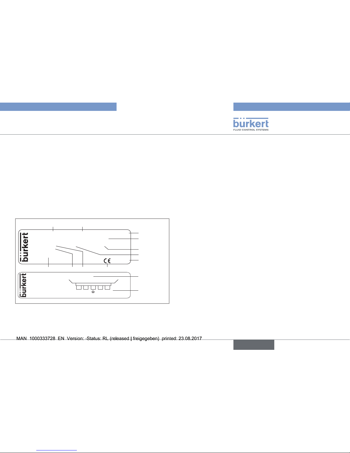
5.3. Description of the rating plates
Supply: 12-36VDC Max1W Output: 1x4-20mA
Cell: C 1,00 Range 5-10000 µS/cm
Fluid: 16Bar Temp -20/100°C IP65-67
S/N 1009
00561672
Made in France
3
4
5
6
7
8911
8222 Conductivity-Transmitter
Made in France
12
13
W43ML
1 2
10
+V
0V
NC
NC
Fig. 1: Name plates of the device (example)
1. Power supply
2. Power consumption
3. Type of output
4. Sensor specifications
5. Protection rating
6. Temperature range of the fluid
7. Construction code
8. Conformity marking
9. Nominal pressure of the fluid
10. Serial number
11. Order code
12. Type of the device and measured value
13. Pin assignment of the M12 fixed connector or the terminal block
English
Page 10
10
Technical data
Type 8222 ELEMENT neutrino
6. TECHNICAL DATA
6.1. Operating conditions
Ambient temperature –10...+60 °C
Air humidity < 85 %, non condensated
Protection rating, with connector
or cable plugged in and cable
gland tightened and cover of the
connecting box fully tightened
and locked
• IP67 and IP65
• NEMA 250, 4X and 6P
6.2. Conformity to standards and
directives
The applied standards, which verify conformity with the EU directives, can be found on the EU-type examination certificate and/or the
EU declaration of conformity (if applicable).
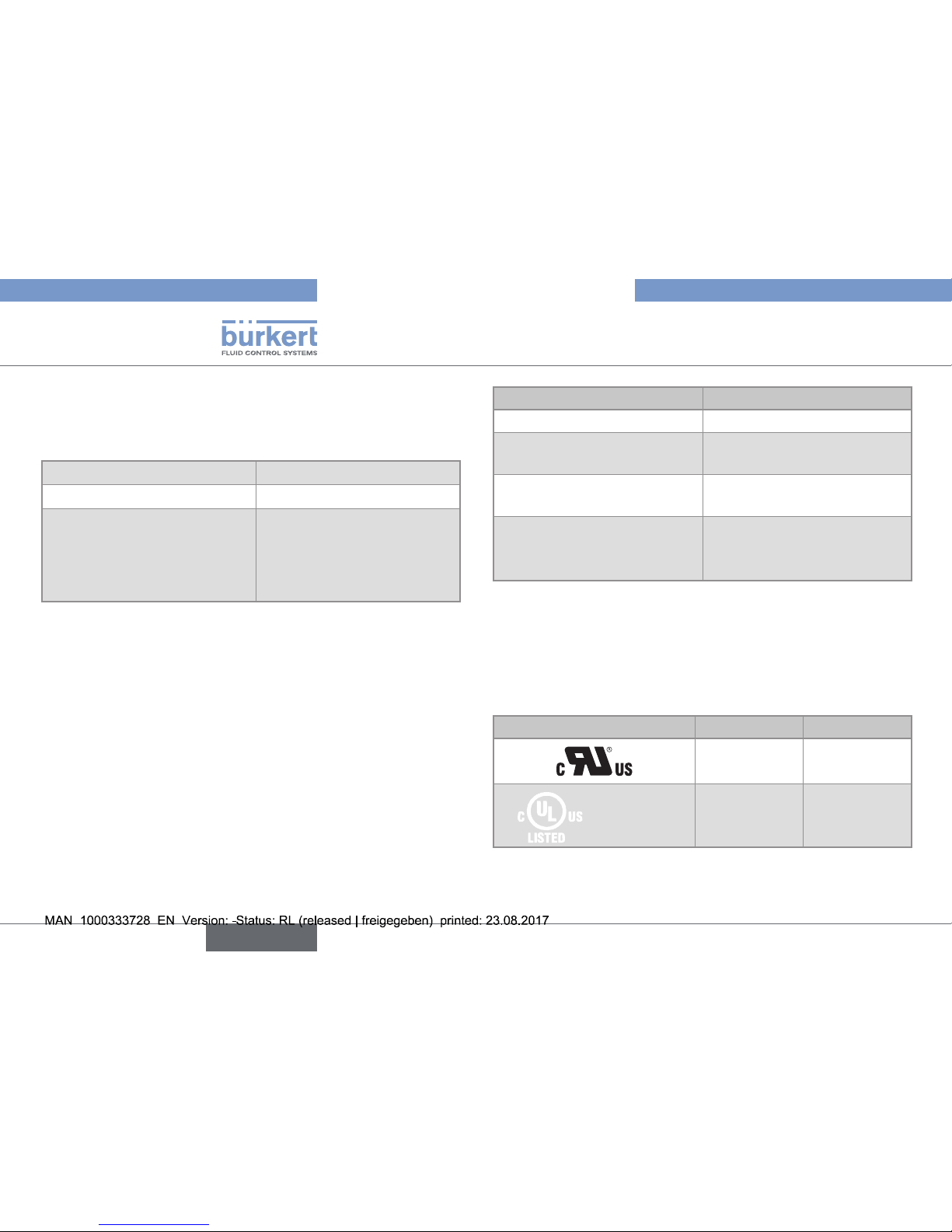
6.2.1. Conformity to the pressure
equipment directive
The device conforms to article 4§1 of the Pressure Equipment
Directive 2014/68/EU under following conditions.
The device can only be used in the following cases (depending on
the max. pressure, the DN of the pipe and the fluid):
Type of fluid Conditions
Fluid group 1, art. 4 §1.c.i DN25 only
Fluid group 2, art. 4 §1.c.i
DN ≤ 32
or PNxDN ≤ 1000
Fluid group 1, art. 4 §1.c.ii
DN ≤ 25
or PNxDN ≤ 2000
Fluid group 2, art. 4 §1.c.ii
DN ≤ 200
or PN ≤ 10
or PNxDN ≤ 5000
6.2.2. UL certification
Products with variable key PU01 or PU02 are UL-certified products
and comply also with the following standards:
• UL 61010-1
• CAN/CSA-C22.2 n°61010-1
Identification on the device Certification Variable key
UL-recognized PU01
Measuring
Equipment
EXXXXXX
®
UL-listed PU02
English
Page 11

11
Technical data
Type 8222 ELEMENT neutrino
6.3. Mechanical data
Part Material
Box / seals stainless steel, PPS / EPDM
Cover / seal PPS / EPDM
M12 fixed connector / Seal PA66 / EPDM
Cable gland / Seal PA66 / EPDM
Nut PVC (or PVDF on request)
Conductivity sensor PVDF
Pt1000 stainless steel 1.4571 (316Ti)
Electrodes
• probe C=1
• probe C=0,1 or C=0,01
• graphite
• stainless steel 1.4571 (316Ti)
• Materials in contact with the fluid:
PVDF, stainless steel 1.4571 (316Ti), graphite, EPDM (only
version with G 3/4'' external threaded sensor)
Stainless steel 316Ti
(C=0,1 ou 0,01)
Stainless steel
316Ti (C=1)
Graphite (C=1)
PVC or
PVDF
PVDF
PPS
EPDM
PA66 / EPDM
Stainless steel
Fig. 2: Materials of the device
6.4. Dimensions
→ Please refer to the technical data sheets regarding the pH- or
redox-meter type 8222 ELEMENT neutrino, available at:
www.burkert.com
English
Page 12

12
Technical data
Type 8222 ELEMENT neutrino
6.5. Fluid data
Process connection
• Version with a G 1 1/2'' nut
• Version with a G 3/4''
external threaded sensor
• Adapter or fitting S022
• Adapter with G 3/4" internal
thread
Fluid pressure
PN16
The max. fluid pressure may be
restricted by the fluid temperature,
the material of the nut and the material
from which the S022 is made (see
Fig. 3, Fig. 4, Fig. 5 and Fig. 6)
Fluid temperature
The max. fluid temperature may be
restricted by the fluid pressure, the
material of the nut and the material
from which the S022 is made (see
Fig. 3, Fig. 4, Fig. 5 and Fig. 6)
Conductivity measurement
• Measurement range
• Internal resolution
• Measuring error
• 0,05 µS/cm to 10 mS/cm
• 1 nS/cm
• ±3 % of the measured value
Temperature probe
Pt1000 integrated in the conductivity sensor
Temperature measurement
• Measurement range
• Accuracy
• –40...+130 °C
• ±1 °C
Temperature compensation
• Automatic (integrated Pt1000)
according to the position of the
selector on the electronic board
(see chap. 9.3)
• Reference temperature = 25 °C
-20 0 +20 +40 +60 +80 +100+120T (°C)
16
15
14
13
12
11
10
9
8
7
6
5
4
3
2
1
0
P (bar)
A
A
B
232
217.6
203
188.6
174
159.6
145
130.6
116
101.6
87
72.5
58
43.5
29
14
0
P (psi)
A: with a PVDF nut or a G 3/4" external threaded sensor;
B: with a PVC nut
The measures have been made at an ambient temperature of 60 °C.
Fig. 3: Fluid temperature / pressure dependency, for the device
with a PVC or a PVDF nut or with a G 3/4'' external
threaded sensor
English
Page 13

13
Technical data
Type 8222 ELEMENT neutrino
16
15
14
13
12
11
10
9
8
7
6
5
4
3
2
1
0
-20 0 +20 +40 +60 +80 +100
T (°C)
P (bar)
+120
PVC
232
217.6
203
188.6
174
159.6
145
130.6
116
101.6
87
72.5
58
43.5
29
14
0
P (psi)
Metal
The measurements have been made at an ambient temperature of 60 °C.
Fig. 6: Fluid temperature / pressure dependency, for the device
with a G 3/4" external threaded sensor and an adapter in
PVC or metal.
16
15
14
13
12
11
10
9
8
7
6
5
4
3
2
1
0
0 +20 +40 +60
T (°C)
P (bar)
PVC + PP
-20
232
217.6
203
188.6
174
159.6
145
130.6
116
101.6
87
72.5
58
43.5
29
14
0
P (psi)
Metal
Fig. 4: Fluid temperature / pressure dependency, for the device
with a PVC nut and an S022 in metal, PVC or PP.
16
15
14
13
12
11
10
9
8
7
6
5
4
3
2
1
0
-20 0 +20 +40 +60 +80 +100
PVC
PP
T (°C)
P (bar)
PVC + PP
+120
232
217.6
203
188.6
174
159.6
145
130.6
116
101.6
87
72.5
58
43.5
29
14
0
P (psi)
Metal
Fig. 5: Fluid temperature / pressure dependency, for the device with
a PVDF nut and an S022 in metal, PVC or PP.
English
Page 14

14
Technical data
Type 8222 ELEMENT neutrino
6.6. Electrical data
Power supply 12...36 V DC, filtered and regulated
Current consumption ≤ 25 mA (12...36 V DC)
Protection against polarity
reversal
yes
Protection against voltage
spikes
yes
Current output
• Accuracy
• Response time
(10 % - 90 %)
• max. loop impedance
4...20 mA
• ±1 % (0,16 mA)
• 5 s
• 1100 W at 36 V DC, 610 W at
24 V DC, 100 W at 12 V DC
6.7. Electrical data specific to the UL
devices
Characteristics of the power
source (not supplied)
• limited energy source (in
accordance to UL 61010-1, § 9.4
• or Low Power Source in
accordance to UL 60950-1
• or Class 2 source in accordance
to UL 1310 or UL 1585
6.8. Probe data
Probe C=0,01
• Measurement range
• Type of fluid
• 0,05...20 µS/cm
• ultra-pure water, pure water
Probe C=0,1
• Measurement range
• Type of fluid
• 0,5...200 µS/cm
• for example: pure water, industrial
wastewater
Probe C=1
• Measurement range
• Type of fluid
• 0,005...10 mS/cm
• for example: industrial wastewater, wastewater
English
Page 15

15
Assembly
Type 8222 ELEMENT neutrino
7. ASSEMBLY
7.1. Safety instructions
DANGER
Risk of injury due to electrical voltage.
▶ If a 12...36 V DC powered version is installed either in a wet
environment or outdoors, all the electrical voltages must be of
max. 35 V DC.
▶ Shut down the electrical power source of all the conductors and
isolate it before carrying out work on the system.
▶ Observe all applicable accident protection and safety regula-
tions for electrical equipment.
WARNING
Risk of injury due to nonconforming assembly.
▶ The device must only be assembled by qualified and skilled staff
with the appropriate tools.
Risk of injury due to unintentional switch on of power supply
or uncontrolled restarting of the installation.
▶ Avoid unintentional activation of the installation.
▶ Guarantee a set or controlled restarting of the process subse-
quent to any intervention on the device.
7.2. Unscrewing the cover on the
connection box
NOTICE
The tightness of the device is not guaranteed when the cover
is removed.
▶ Take all the precautions to prevent the projection of liquid inside
the housing.
The connection box is fitted
with a locking system.
→ Using a screwdriver with
a suitable head, turn
the latch to the unlock
position to unlock the
connection box.
English
Page 16

16
Assembly
Type 8222 ELEMENT neutrino
→ Unscrew the cover on
the connection box by
hand.
Fig. 7: Unscrewing the cover on the connection box
7.3. Fitting the cover to the
connection box
B
→ Check that seal
"B" on the cover is
in good condition.
Replace it if necessary
(see chap. 11 and
chap. 10.3).
slots
polarising slots
→ Position the polarising
slots on the cover in
the axis of the slots on
the box: 3 positions
are possible.
→ Tighten the cover on
the connection box.
→ Using a screwdriver
with a suitable head,
turn the latch to the
lock position to lock
the cover.
Fig. 8: Fitting the cover on the connection box
English
Page 17

17
Installation and wiring
Type 8222 ELEMENT neutrino
WARNING
Risk of injury due to nonconforming installation.
▶ The electrical and the fluid installation can only be carried out by
qualified and skilled staff with the appropriate tools.
▶ Install appropriate safety devices (correctly rated fuse and/or
circuit-breaker).
▶ Respect the assembly instructions for the fitting or the adapter
used.
Risk of injury due to unintentional switch on of power supply
or uncontrolled restarting of the installation.
▶ Avoid unintentional activation of the installation.
▶ Guarantee a set or controlled restarting of the process subse-
quent to any intervention on the device.
WARNING
Risk of injury if the fluid pressure/ temperature dependency
is not respected.
▶ Take into account the fluid pressure/ temperature dependency
according to the materials from which the fitting is made (see
chap. 6.5).
▶ Comply with the Pressure Equipment Directive 2014/68/EU.
8. INSTALLATION AND WIRING
8.1. Safety instructions
DANGER
Risk of injury due to high pressure in the installation.
▶ Stop the circulation of fluid, cut off the pressure and drain the
pipe before loosening the process connections.
Risk of injury due to electrical voltage.
▶ If a 12...36 V DC powered version is installed either in a wet
environment or outdoors, all the electrical voltages must be of
max. 35 V DC.
▶ Shut down the electrical power source of all the conductors and
isolate it before carrying out work on the system.
▶ Observe all applicable accident protection and safety regula-
tions for electrical equipment.
Risk of injury due to the nature of the fluid.
▶ Respect the regulations on accident prevention and safety relat-
ing to the use of aggressive fluids.
Risk of injury due to the high temperature of the fluid.
▶ Use safety gloves to handle the device.
English
Page 18

18
Installation and wiring
Type 8222 ELEMENT neutrino
Protect this device against electromagnetic interference,
ultraviolet rays and, when installed outdoors, the effects of
the climatic conditions.
8.2. Installation onto the pipe
If the conductivity is measured in liquids containing solids
that may leave deposits in the bottom of the pipe, use installation position 1 (see Fig. 9)
The device is available with an external threaded sensor or with a
G 1 1/2'' nut. The device with a nut can be installed on a pipe by
means of an S022 adapter or fitting. The device with an external
threaded sensor can be installed on a pipe or a tank wall by means
of an internal threaded adapter.
8.2.1. Installation of a device with a
G 1 1/2" nut
Prefer mounting position “1” to install a device with probe
C=0,1 or C=0,01.
→ Choose an appropriate position in the pipe to install the fitting
(see Fig. 9).
→ Install the adapter or the fitting on the pipe according to the
Operating Instructions of the adapter or fitting used.
1 2
Direction of the fluid
Fig. 9: Mounting positions of the fitting/device unit in the pipe
→ Install the device on the fitting (see Fig. 10).
B
→ Check that
seal B is on
the fitting and
that it is not
damaged.
Replace
the seal if
necessary.
→ Carefully insert
the device into
the fitting.
English
Page 19

19
Installation and wiring
Type 8222 ELEMENT neutrino
Ø 24 min.
21,5
1)
Ø 27,5
H8
G3/4''
R 0,25 min.
3,3
1x45°
0,5 x 45°
1)
minimal internal thread depth
Fig. 11: Threading jig for the adapter [mm]
→ Install the device into the adapter.
→ Position the device in such a way that the markings (see zoom in
Fig. 10) located on either side of the electronics box are parallel
to the pipe.
→ Position the
device in such
a way that the
markings (see
zoom) located
on either side
of the electronics box are
parallel to the
pipe.
→ Tighten by hand
the nut G 1 1/2"
on the fitting.
Fig. 10: Installation of the device into a fitting
8.2.2. Installation of a device with a G 3/4"
external threaded sensor
→ Check that the seal is on the threaded sensor.
→ Check the condition of the seal and replace it if necessary (see
chap. 10.4)
→ Install the device on the pipe or the tank wall by means of an
adapter that respects the threading jig from Fig. 11
English
Page 20

20
Installation and wiring
Type 8222 ELEMENT neutrino
8.3. Wiring
DANGER
Risk of injury due to electrical voltage.
▶ If a 12...36 V DC powered version is installed either in a wet
environment or outdoors, all the electrical voltages must be of
max. 35 V DC.
▶ Shut down the electrical power source of all the conductors and
isolate it before carrying out work on the system.
▶ Observe all applicable accident protection and safety regula-
tions for electrical equipment.
• Use a high quality electrical power supply (filtered and
regulated).
• Make sure the installation is equipotential.
8.3.1. Electrical connections
Version Type of connection
with a male M12 fixed
connector
5-pin female M12 connector (not
supplied).
For the M12 connector with order code
917116, use a shielded cable:
• diameter: 3...6.5 mm
• wire cross section: max. 0.75 mm
2
Version Type of connection
With a 5-pin terminal
block and a cable
gland
Shielded cable (not provided):
• diameter: 4...8 mm
• wires in compliance with the characteristics of the Table 1
Table 1 : Specifications of the wires composing the cable for a
version with cable gland
Wire specifications Dimensions
• Max clamping area 0.14...1.5 mm
2
• Single core H05(07) V-U 0.25...1.5 mm
2
• Flexible wire H05(07) V-K 0.25...1.5 mm
2
• With non-insulated end connection 0.25...1.5 mm
2
• With insulated end connection 0.25...0.75 mm
2
8.3.2. Wiring a version with cable gland
→ Select a cable that meets the specifications detailed in
chap. "8.3.1. Electrical connections".
75-85 mm
8-9 mm
→ Strip 75 to 85 mm of the
cable.
→ Expose 8 to 9 mm of the wires
on the stripped cable.
Fig. 12: Stripping the cable and exposing the wires
English
Page 21

21
Installation and wiring
Type 8222 ELEMENT neutrino
12...36 V DC
+ -
out 2
out 1
0V
+V
+ -
Power supply
4...20 mA input at external
instrument
12...36 V DC
+
-
out 2
out 1
0V
+V
+
-
Power supply
4...20 mA input at external
instrument
Fig. 14: Possible connections of the 4...20 mA current output on a
version with cable gland
→ Fit the cover to the connection box (see chap. 7.3).
A B
→ Unscrew and remove the
cable gland nut [A].
→ Remove the stopper [B] from
the cable gland.
→ Unscrew the cover on
the connection box (see
chap. 7.2)
→ Thread the cable through the
cable gland nut and the cable
gland.
→ Pull the cable inside the box
until the end of the stripped
part of the cable sticks out of
the cable gland by 5 to 6 mm.
→ Roll a cable clamp around the
cable jacket (twice).
→ Tighten the cable clamp.
→ Pull the cable from the
outside of the box to check
that it is secure.
Fig. 13: Threading the cable into the cable gland
→ Tighten the cable gland.
→ Connect the 4...20 mA output (see Fig. 14).
English
Page 22

22
Installation and wiring
Type 8222 ELEMENT neutrino
8.3.3. Assembling and wiring the female connector, order code 917116
See chap. "11. Spare parts and accessories"
1 2
→ Completely unscrew nut [1].
→ Remove the rear section of connector [2].
5,5
11,5
20
→ Thread the cable through the nut and the rear part of the
connector.
→ Strip 20 mm of the cable.
→ Cut the central wire (earth) so that its length is equal to
11.5 mm.
→ Expose 5.5 mm of the wires on the stripped cable.
→ Insert each wire into the appropriate pin (see pin allocation
in chap. 8.3.4).
→ Tighten the connector nut.
Fig. 15: M12 multi-pin connector (not provided)
English
Page 23

23
Installation and wiring
Type 8222 ELEMENT neutrino
8.3.4. Wiring a version with an M12 fixed
connector
1
2
3
4
V+ (12...36 V DC)
Not connected
0 V
Not connected
Fig. 16: Pin assignment of the M12 fixed connector
Pin of the M12 female cable
available as an accessory
(order code 438680)
Signal Colour of the wire
1 V+ brown
2 NC white
3 0 V blue
4 NC black
5
green/yellow or grey
The M12 fixed connector of the device is adjustable:
→ Unscrew the locknut.
→ Turn the fixed connector to the desired position, by 360° max. so
as not to twist the cables inside the housing.
→ Tighten the locknut using a spanner, while keeping the fixed con-
nector in the desired position.
12...36 V DC
+ -
+ -
1
2
3
4
4...20 mA input at
external instrument
Power supply
brown
green/yellow or
grey
blue
+ -
1
2
3
4
12...36 V DC
+ -
Power supply
brown
green/yellow or
grey
blue
4...20 mA input at
external instrument
Fig. 17: Possible connections of the 4...20 mA current output on a
version with M12 fixed connector
English
Page 24

24
Adjustment and commissioning
Type 8222 ELEMENT neutrino
Internal wiring of the M12 fixed connector on the terminal block
Terminals Colour of the wire connecting the fixed
connector to the terminal block
V+ red
0 V black
green
OUT1 grey
OUT2 orange
9. ADJUSTMENT AND
COMMISSIONING
9.1. Safety instructions
DANGER
Risk of injury due to electrical voltage.
▶ Observe all applicable accident protection and safety regula-
tions for electrical equipment.
Risk of injury due to the nature of the fluid.
▶ Respect the regulations on accident prevention and safety relat-
ing to the use of aggressive fluids.
WARNING
Risk of injury due to nonconforming adjustment.
Nonconforming adjustment could lead to injuries and damage the
device and its surroundings.
▶ The operators in charge of adjustment must have read and
understood the contents of these Operating Instructions.
▶ In particular, observe the safety recommendations and intended
use.
▶ The device/installation must only be adjusted by suitably trained
staff.
English
Page 25

25
Adjustment and commissioning
Type 8222 ELEMENT neutrino
WARNING
Danger due to nonconforming commissioning.
Nonconforming commissioning could lead to injuries and damage
the device and its surroundings.
▶ Before commissioning, make sure that the staff in charge
have read and fully understood the contents of the Operating
Instructions.
▶ In particular, observe the safety recommendations and intended
use.
▶ The device/installation must only be commissioned by suitably
trained staff.
9.2. Description of the connection box
The box contains the terminal block for electrical connection and
elements used for adjustment:
• a selector of the conductivity or temperature range associated
with the 4...20 mA output
• a green LED to indicate that the device is energized
• a red LED to:
- indicate the type of probe that is fitted on the device (see chap. 9.3)
- indicate a problem (see chap. 10.5)
• a push-button (not used).
Selector
Push-button (not
used)
Red LED
Green LED
Red mark
Fig. 18: Connection box
English
Page 26

26
Adjustment and commissioning
Type 8222 ELEMENT neutrino
9.3. Choosing the conductivity or
temperature range associated
with the 4...20 mA output
The following procedure is valid for the devices with a series
number equal or higher than 3000. See the name plate of
the device.
Upon power-up and every ten seconds afterwards, the red LED flashes:
• once if the device is equipped with a probe C=1
• twice if the device is equipped with a probe C=0,1
• three times if the device is equipped with a probe C=0,01
The selector (see Fig. 18) allows for choosing the conductivity
or temperature range associated with the 4...20 mA output . The
following tables give, depending on the cell constant and on the
position of the selector (from 0 to 9 and A to F, the uneven positions being marked by a full stop), the conductivity or temperature
range associated to the 4...20 mA output, the applied temperature
compensation and the measuring range of the recommended
conductivity.
The compensation graph “NaCl” is valid for the 10 to 90 °C temperature range and a concentration of 0,2 %.
Table 2 : Sensor C=0,01
Selector
position
4...20 mA
output range
Temperature
compensation
acc. to
Recommended
conductivity
measurement
range
0 (default
position)
0...20 µS/cm NaCl 2...20 µS/cm
1 0...20 µS/cm none 2...20 µS/cm
2 0...10 µS/cm NaCl 1...10 µS/cm
3 0...10 µS/cm none 1...10 µS/cm
4 0...5 µS/cm NaCl 0,5...5 µS/cm
5 0...5 µS/cm none 0,5...5 µS/cm
6 0...2 µS/cm NaCl 0,2...2 µS/cm
7 0...2 µS/cm none 0,2...2 µS/cm
8 0...1 µS/cm ultra pure
water
0,05...1 µS/cm
9 0...1 µS/cm none 0,05...1 µS/cm
A 0...0,5 µS/cm ultra pure
water
0,05...0,5 µS/cm
B 0...0,5 µS/cm none 0,05...0,5 µS/cm
C, D, E 0...0 µS/cm
1)
- -
F –40...+130 °C - -
English
Page 27

27
Adjustment and commissioning
Type 8222 ELEMENT neutrino
Table 3 : Sensor C=0,1
Selector
position
4...20 mA
output range
Temperature
compensation
acc. to
Recommended
conductivity
measurement
range
0 (default
position)
0...200 µS/cm NaCl 20...200 µS/cm
1 0...200 µS/cm none 20...200 µS/cm
2 0...100 µS/cm NaCl 10...100 µS/cm
3 0...100 µS/cm none 10...100 µS/cm
4 0...50 µS/cm NaCl 5...50 µS/cm
5 0...50 µS/cm none 5...50 µS/cm
6 0...20 µS/cm NaCl 2...20 µS/cm
7 0...20 µS/cm none 2...20 µS/cm
8 0...10 µS/cm NaCl 1...10 µS/cm
9 0...10 µS/cm none 1...10 µS/cm
A 0...5 µS/cm NaCl 0,5...5 µS/cm
B 0...5 µS/cm none 0,5...5 µS/cm
C 0...2 µS/cm NaCl 0,5...2 µS/cm
D 0...2 µS/cm none 0,5...2 µS/cm
E 0...0 µS/cm
1)
- -
F –40...+130 °C - -
1)
When these positions are selected, the 4...20 mA current output is
not used. Its value is always 4 mA.
Table 4 : Sensor C=1
Selector
position
4...20 mA
output range
Temperature
compensation
acc. to
Recommended
conductivity
measurement
range
0 (default
position)
0...10 mS/cm NaCl 1...10 mS/cm
1 0...10 mS/cm none 1...10 mS/cm
2 0...5 mS/cm NaCl 0,5...5 mS/cm
3 0...5 mS/cm none 0,5...5 mS/cm
4 0...2 mS/cm NaCl 0,2...2 mS/cm
5 0...2 mS/cm none 0,2...2 mS/cm
6 0...1 mS/cm NaCl 0,1...1 mS/cm
7 0...1 mS/cm none 0,1...1 mS/cm
8 0...500 µS/cm NaCl 50...500 µS/cm
9 0...500 µS/cm none 50...500 µS/cm
A 0...200 µS/cm NaCl 20...200 µS/cm
B 0...200 µS/cm none 20...200 µS/cm
C 0...100 µS/cm NaCl 10...100 µS/cm
D 0...100 µS/cm none 10...100 µS/cm
E 0...50 µS/cm NaCl 5...50 µS/cm
F –40...+130 °C - -
→ Position the red mark of the selector on the desired range (see
Fig. 18). In the example in Fig. 18, the selector is placed on
position 5.
English
Page 28

28
Maintenance and troubleshooting
Type 8222 ELEMENT neutrino
9.4. Checking the cell constant of the
conductivity sensor
Each sensor is delivered calibrated.
Take the temperature compensation into account.
The following procedure makes it possible to check the exactness of
the device:
→ Prepare a calibration solution adapted to your process or the
sensor (see chap. "11. Spare parts and accessories").
→ Place the sensor into the calibration solution.
→ Wait for the temperature to stabilise.
→ Check the exactness of the measured value transmitted by the
transmitter to the acquisition system (PLC,...).
→ If necessary, correct the measure on the acquisition system
(PLC, ...).
10. MAINTENANCE AND
TROUBLESHOOTING
10.1. Safety instructions
DANGER
Risk of injury due to high pressure in the installation.
▶ Stop the circulation of fluid, cut off the pressure and drain the
pipe before loosening the process connections.
Risk of injury due to electrical voltage.
▶ Shut down the electrical power source of all the conductors and
isolate it before carrying out work on the system.
▶ Observe all applicable accident protection and safety regula-
tions for electrical equipment.
Risk of injury due to the nature of the fluid.
▶ Respect the regulations on accident prevention and safety relat-
ing to the use of dangerous fluids.
Risk of injury due to the high temperature of the fluid.
▶ Use safety gloves to handle the device.
English
Page 29

29
Maintenance and troubleshooting
Type 8222 ELEMENT neutrino
WARNING
Risk of injury due to nonconforming maintenance.
▶ Maintenance must only be carried out by qualified and skilled
staff with the appropriate tools.
▶ Ensure that the restart of the installation is controlled after any
interventions.
10.2. Device and conductivity sensor
maintenance
• During cleaning of the sensor, take care not to scratch its
surface.
• Store the sensor dry.
The device can be cleaned with a cloth dampened with water or a
detergent compatible with the materials the device is made of.
→ Regularly check if the conductivity sensor is dirty; clean it if nec-
essary using a compatible product.
Please feel free to contact your Bürkert supplier for any additional
information.
10.3. Replacing the cover seal on the
connection box
→ Using a screwdriver
with a suitable head,
turn the latch to
the unlock position
to unlock the connection box.
→ Unscrew the cover
by hand.
English
Page 30

30
Maintenance and troubleshooting
Type 8222 ELEMENT neutrino
out 2
out 1
0V
+V
→ On a version with
cable gland, locate
the colours of the
wires connected to
the terminal block.
→ Disconnect the
wires from the
terminal block by
pressing the plugs
on the terminal block
with a screwdriver.
B
→ Remove the worn
seal "B" from the
cover.
→ Put the new seal "B"
in place in the cover.
→ Reconnect the wires
to the terminal block
(for a version with
M12 fixed connector, see table,
chap. 8.3.4 for the
references).
→ Put the cover in
place.
→ Fully tighten the
cover by hand to
guarantee tightness.
→ Using a screwdriver
with a suitable head,
turn the latch to the
lock position to lock
the cover.
Fig. 19: Replacing the cover seal on the connection box
English
Page 31

31
Maintenance and troubleshooting
Type 8222 ELEMENT neutrino
10.4. Replacing the seal of the G 3/4''
threaded sensor
C
→ Remove the worn seal "C"
without damaging the groove
nor the threads.
→ Put the new seal "C" in place
in the groove.
English
Page 32

32
Maintenance and troubleshooting
Type 8222 ELEMENT neutrino
10.5. If you encounter problems
Red LED status 4...20 mA output value Possible cause Recommended action
flashes (once per
second)
4...20 mA Fluid temperature outside
the operating range
(–20...+100 °C).
→ Check the fluid temperature.
→ Put the fluid temperature back to within the operating
range (–20...+100 °C).
ON 22 mA • Connection with temper-
ature probe interrupted.
• Parameters of the device
cannot be read.
→ Power off the device.
→ Power on the device.
→ If the fault persists, contact your Bürkert retailer.
flashes (once to three
times every 10 s)
4 mA, whatever the
measured conductivity or
temperature value.
The position of the selector of
the electronic board may be
incorrectly set.
→ Adjust the position of the selector depending on the
fluid conductivity (or temperature): see chap. 9.3.
flashes (once to three
times every 10 s)
20 mA, whatever the
measured conductivity or
temperature value.
The position of the selector of
the electronic board may be
incorrectly set.
→ Adjust the position of the selector depending on the
fluid conductivity (or temperature): see chap. 9.3.
English
Page 33

33
Spare parts and accessories
Type 8222 ELEMENT neutrino
11. SPARE PARTS AND
ACCESSORIES
CAUTION
Risk of injury and/or damage caused by the use of unsuitable
parts.
Incorrect accessories and unsuitable replacement parts may
cause injuries and damage the device and the surrounding area.
▶ Use only original accessories and original replacement parts
from Bürkert.
Spare part Order code
EPDM seal for the G 3/4'' external threaded
sensor
561955
EPDM seal for the tightness between the
cover and the housing
561752
Accessories Order code
5-pin female M12 connector, to be wired 917116
5-pin female M12 female connector, moulded
on shielded cable (2 m)
438680
Calibration solution, 300 ml, 5 µS 440015
Calibration solution, 300 ml, 15 µS 440016
Calibration solution, 300 ml, 100 µS 440017
Calibration solution, 300 ml, 706 µS 440018
Calibration solution, 300 ml, 1413 µS 440019
12. PACKAGING, TRANSPORT
NOTICE
Damage due to transport
Transport may damage an insufficiently protected device.
▶ Transport the device in shock-resistant packaging and away
from humidity and dirt.
▶ Do not expose the device to temperatures that may exceed the
admissible storage temperature range.
▶ Protect the electrical interfaces using protective plugs.
13. STORAGE
NOTICE
Poor storage can damage the device.
▶ Store the device in a dry place away from dust.
▶ Storage temperature: –10...+60 °C.
English
Page 34

34
Disposal of the device
Type 8222 ELEMENT neutrino
14. DISPOSAL OF THE DEVICE
→ Dispose of the device and its packaging in an environmentally-
friendly way.
NOTICE
Damage to the environment caused by products contaminated by fluids.
▶ Keep to the existing provisions on the subject of waste disposal
and environmental protection.
English
Page 35

Page 36

www.burkert.com
 Loading...