

Page 1

Operating Instructions
Bedienungsanleitung
Instructions de Service
Type 0258
Modular 2 and 3-way motor control valve
Modulares 2- und 3-Wege-Motorregelventil
Vanne de régulation motorisée
modulaire à 2 et 3 voies
Page 2
We reserve the right to make technical changes without notice.
Technische Änderungen vorbehalten.
Sous resérve de modification techniques.
© 2004 Bürkert Werke GmbH & Co. KG
Operating Instructions 0601/00_EU-EN_00804858
Page 3
Modular 2 and 3-way
motor control valve
GENERAL NOTES ....................................................................................... 3
Symbols ...................................................................................................... 3
Trademarks ................................................................................................ 3
Safety notes .............................................................................................. 3
Application Guidelines............................................................................ 4
Scope of delivery ..................................................................................... 4
Warranty conditions ................................................................................ 4
Approval ..................................................................................................... 5
SYSTEM DESCRIPTION ............................................................................ 6
Application area ....................................................................................... 6
Design......................................................................................................... 6
Function ..................................................................................................... 6
Control functions of the valves............................................................. 7
Flow characteristic curves ..................................................................... 7
Marking....................................................................................................... 8
Basic module ............................................................................................ 9
Filter module ....................................................................................................... 9
2-way flow valve ................................................................................................. 9
3-way mixing or distribution valve ............................................................... 10
Check valve ...................................................................................................... 10
Shut-off valve ................................................................................................... 10
english
TECHNICAL DATA ...................................................................................... 11
Dimensions .............................................................................................. 11
4-way block ...................................................................................................... 11
Port connections (hose)............................................................................... 11
General data ........................................................................................... 12
Mechanical data .................................................................................... 12
Electrical data.........................................................................................13
Electrical connections .......................................................................... 14
Plug configuration Mod ................................................................................ 14
Plug configuration LC .................................................................................... 14
OPERATING AND DISPLAY ELEMENTS ............................................. 15
Emergency manual override ................................................................15
0258 - 1
Page 4
Optical position indicator..................................................................... 15
PUTTING INTO OPERATION...................................................................16
Safety notes ............................................................................................ 16
Installation ............................................................................................... 16
OPERATION AND FUNCTION ................................................................ 16
Safety notes ............................................................................................ 16
english
ACCESSORY ............................................................................................. 17
MAINTENANCE ........................................................................................... 19
TRANSPORT AND STORAGE................................................................ 20
DISPOSAL ................................................................................................... 20
Modular filter type 250, solo ............................................................... 17
Dimensional drawings for modular filter type 250, solo ............... 17
3-way check valve block with shut-off valve .................................. 18
Dimensional drawings for 3-way check valve block
with shut-off valve .................................................................................18
Safety notes ............................................................................................ 19
Service ..................................................................................................... 19
Service intervals..................................................................................... 19
Correction of faults ............................................................................... 19
2 - 0258
Page 5
GENERAL NOTES
Symbols
The following symbols are used in these operating instructions:
Marks a work step that you must carry out.
ATTENTION!
NOTE
marks notes on whose non-observance your health or the
functioning of the device will be endangered.
marks important additional information, tips and
recommendations.
Trademarks
Ultramid® is a registered Trademark of BASF.
Grivory® is a registered Trademark of EMS-Grivory.
Safety notes
Please observe the notes in these operating instructions together with the
conditions of use and permitted data that are specified in the data sheet, in
order that the devices will function perfectly and remain operable for a long
time:
• Keep to standard engineering rules in planning the use of and operating
the device!
• Only use the device as intended, for the application agreed with the
Bürkert company.
• Interference with the device is only allowed by specialist personnel using
suitable tools!
• Observe the current regulations on accident prevention and safety for
electrical devices during operation, maintenance and repair of the device!
• Before interfering with the system, always switch off the voltage!
• Avoid undue mechanical force and stress when installing the motor control
valve and when connecting the lines to the hose connections.
• Take suitable precautions to prevent unintended operation or damage by
unauthorized action!
• Only use the device in its original configuration!
• On non-observance of this note and unauthorized interference with the
device, we will refuse all liability and the guarantee on device and
accessories will become void.
english
0258 - 3
Page 6
Application Guidelines
The modular 2 and 3-way motorized regulating valve of Type 0258 is
preferably used as a control element for hot water or coolant circuits in buses,
goods vehicles, floating and rail vehicles, as well as in machine tool
construction. The configuration that is required for your special application
will be drawn up by our Field Service employees. Only use the Type 0258
modular 2 and 3-way motor control valve for the applications agreed with the
Bürkert company. Any other use will have to be agreed with the Customer
Service of the Bürkert company.
english
Scope of delivery
Immediately after receipt of a shipment, make sure that the contents are
undamaged and match the scope of delivery stated on the packing slip.
In case of any discrepancies, please contact our Call Center:
or your local Bürkert Sales Centre immediately.
Bürkert Fluid Control Systems
Call Center
Chr.-Bürkert-Str. 13-17
D-76453 Ingelfingen
Tel. : 07940-10111
Fax: 07940-10448
E-mail: info@de.buerkert.com
Warranty conditions
This document contains no warranty statements. In this connection we refer
to our general sales and business conditions. A prerequisite for validity of the
warranty is use of the device als intended with observance of the specified
conditions of use.
ATTENTION!
4 - 0258
The warranty only extends to the freedom from faults of the
motor control valve and its components.
No liability will be accepted for consequential damage of any
kind that may arise from failure or malfunctioning of the
device.
Page 7

Approval
Devices that carry the e1 marking have been approved by the Federal Office
for Motorised Transport under the type approval number
e1*72/245*95/54*3187*00
and will be brought into circulation with the indicated approval designation.
1
e
023187
You can obtain an excerpt from the type approval from the address below
Bürkert Werke GmbH & Co KG
Zulassungsbeauftragter
Christian Bürkert Str.13-17
74653 Ingelfingen
english
0258 - 5
Page 8
SYSTEM DESCRIPTION
Application area
The modular 2 and 3-way motorized regulating valve of Type 0258 is
preferably used as a control element for hot water or coolant circuits in buses,
goods vehicles, floating and rail vehicles, as well as in machine tool
construction.
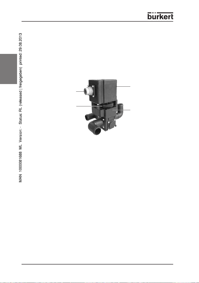
Design
english
Emergency manual override
(optical position indicator)
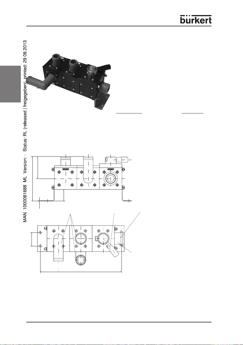
The Type 0258 motorised regulating valve has a modular design, and is
mounted individually or assembled into blocks. Up to 4 valves can be
combined in one block. It can be used as either 2 or 3-way valve, as desired,
and contains ceramic sealing elements, while the valve body is made from
plastic.
The electrical rotary actuator with d.c. motor that is used here consists of
either a maintenance-free flat drive1) (LC) with an AMP plug, or of a powerful,
maintenance-free spur drive2) (Mod) with a magnetic clutch coupling and
Hirschmann plug (options possible), an emergency manual override with an
optical position indicator and one or more valve modules.
In connection with the emergency manual override, the drives have a rotation
angle of 180°. The drives may not be operated without emergency manual
override, as the position feedback can otherwise become maladjusted.
1)
2)
Electrical connection
(AMP or circular
connector according
to DIN 43651,
Hirschmann)
Flat drive (LC): referred to as "LC" in the following text
Spur drive (Mod): referred to as "Mod" in the following text
Motor drive powerful spur drive with
magnetic coupling (Mod) or
flat drive (LC), with
position feedback in each
case
Valve module
Function
By means of a shaft, the drive moves a regulating disk over a fixed disk made
from ceramic oxide, and thereby alternately closes the valve seats A and B
with a sliding transition.
The flow values (2-way), mixing or distribution ratios (3-way) are continually
variable depending on the rotation angle.
The position feedback takes places using a potentiometer.
6 - 0258
Page 9
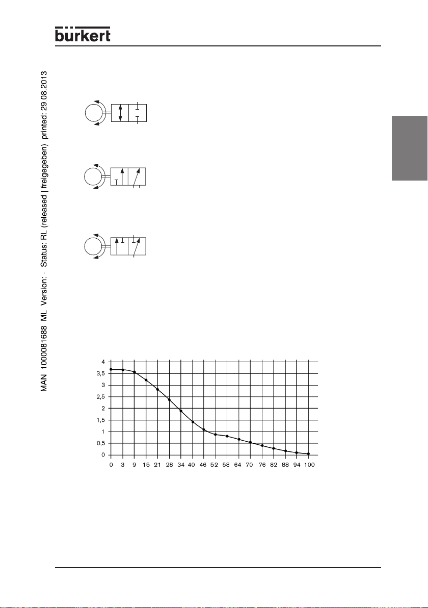
Control functions of the valves
Control function I
A
2-way valve for continuous control of the flow rate in
M
outlet port A,
motor-driven, holds position with no power
P
Control function E
P
3-way valve for continuous mixing of the incoming flows A
M
and B to the port P,
motor-driven, holds position with no power
A B
Control function F
B
A
3-way valve for continuous distribution of the incoming
M
flow P to the outlet ports A and B,
motor-driven, holds position with no power
P
Flow characteristic curves
The flow
shown in the following diagrams. The Kv set-value of 1 m 3 is being prepared.
1)
characteristic curves for the Kv set-values of 3 m3 and 6 m3 are
english
Flow characteristic curves2) Kv-Sollwert = 3 m
/h]
3
Kv value [m
Potentiometer3) [%]
1)
Flow: Kv value water [m³/h],
port.
2)
only Mod drive type
3 )
in relation to the total stroke of the potentiometer = 100 %
4 )
Pressure quoted in [bar]: over-pressure with regard to atmospheric pressure
measurement at +20 °C, 1 bar
3
3 )
pressure at valve inlet port and free outlet
0258 - 7
Page 10
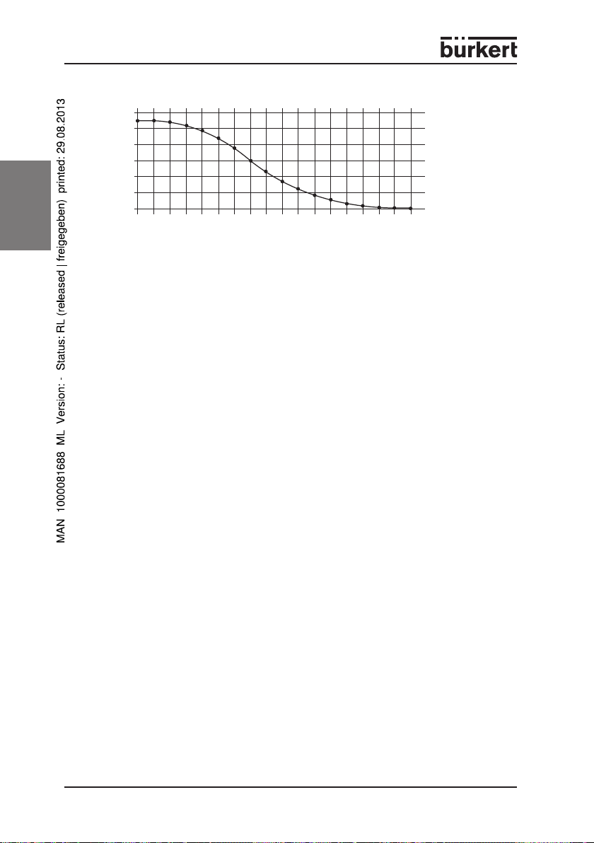
Flow characteristic curves1) Kv set-value = 6 m
english
1)
2)
Marking
The motorised regulating valve is marked with two labels.
The rating label for the complete device (valve block) is located on the lower
left side. The upper line gives the device specification key "SYST-0258", while
the lower line gives the identity number and the encoded date of
manufacture.
Every drive also has its own rating plate with the following content:
• Specification key/Drawing No. e.g.: 0258-G665-205-00,
• Voltage and type of voltage: 24 V DC,
• Power consumption: e.g. 3.0 W,
• Rotation angle: e.g.: 28 s / 180°,
• Rated pressure: e.g.: 0 ... 2.5 bar,
• Identity number and the encrypted date of construction.
6
6
/h]
3
5
5
4
4
3
3
Kv value [m
2
2
1
1
0
0
0
9
0
9
33
33
45
57 70 82 94
45
21
21
57 70 82 94
Potentiometer2) [%]
only Mod drive type
in relation to the total stroke of the potentiometer = 100 %
3
8 - 0258
Page 11
Basic module
4
2
1
3
You can use all basic modules individually or in a block.
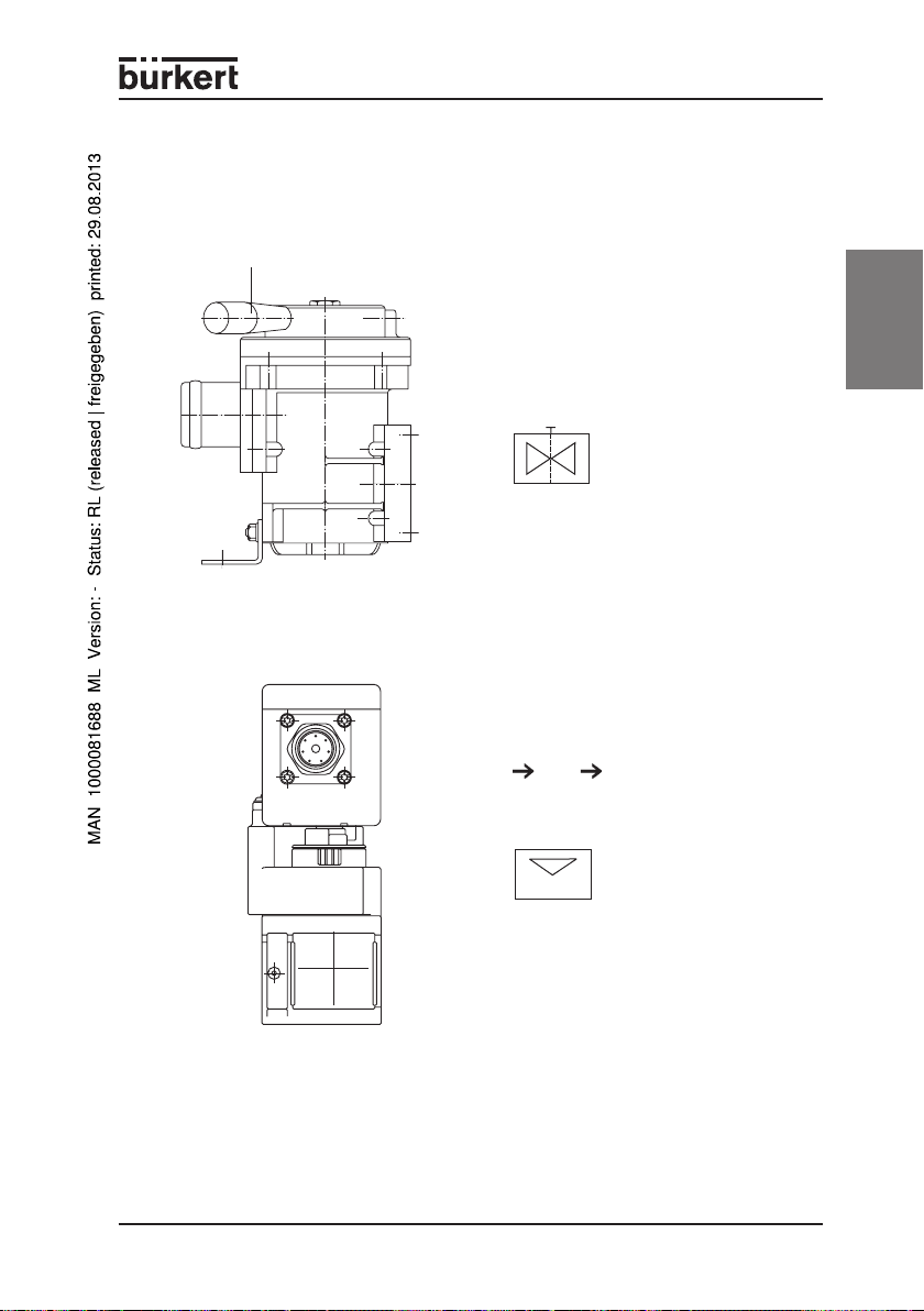
Filter module
manual lever
Description
The filter module can be shut off by
hand. Note the direction of flow.
As an option, the filter module can be
fitted with a magnetic insert.
Block symbol
english
2-way flow valve
4
Description
The 2-way flow valve is continuously
operated.
The direction of flow:
P A, P B
Block symbol
2
0258 - 9
Page 12
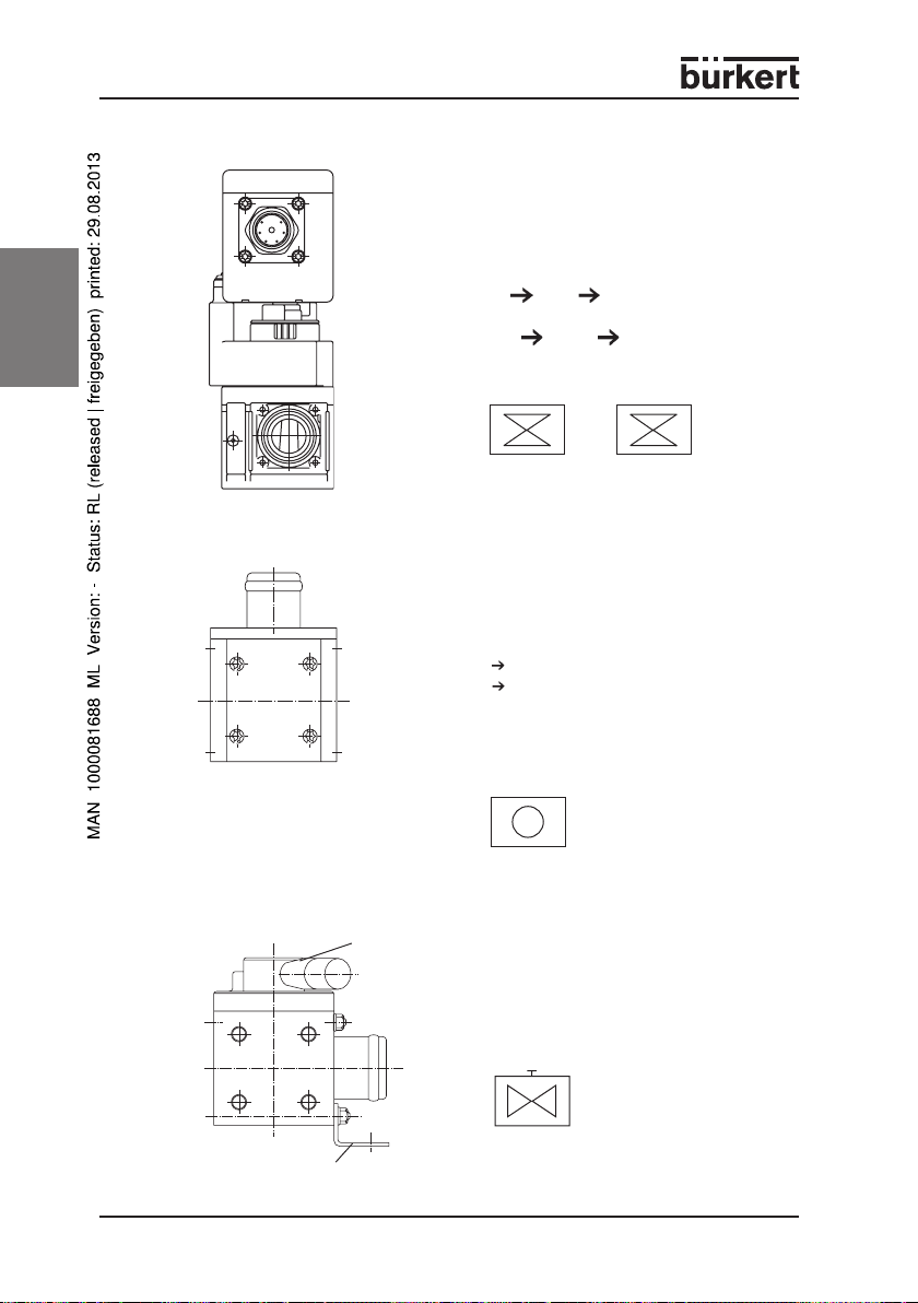
3-way mixing or distribution valve
english
Check valve
Description
The 3-way mixing or distribution valve is
continuously operated.
The directions of flow
• in the distribution valve:
P A, P B
• in the mixing or distribution valve:
P1 A, P2 A
Block symbols
1
4
2
E
3
1
4
2
F
3
Mixing Distribution
Description
The check valve has a collection
function. Manual override is possible.
Manual lever at the left stop:
P A closed
P B open
Note the direction of flow.
Block symbol
1
4
R
2
3
Shut-off valve
10 - 0258
Mounting angle
Hand lever
Description
The shut-off valve is operated
manually. The direction of flow is freely
selectable.
Block symbol
4
2
Page 13
TECHNICAL DATA
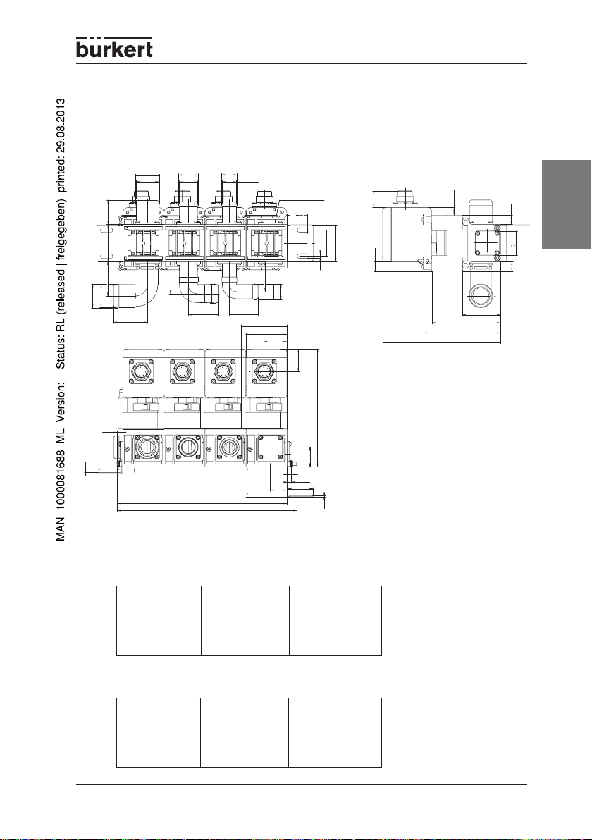
Dimensions
4-way block
Ø36,5
Ø34,5
TU35
37,6
57
TU35
52,5
Ø 34,5
Ø 36,5
51,85
8,88
38,5
1,5
49,1
10,5
Ø29,8
Ø27,8
35,6
TU28
TU28
47
259,5
Ø 27,8
276
Ø 29,8
Ø23,4
35,6
Ø
TU22
TU22
44
21,8
70,1
46,1
63
35,2
Abschlussplatte
19
Ø23,8
Ø21,8
34,5
12
40
7
25,7
56
14,44
180,7
11,44
105,2
118,2
58,2
14,5
14,5
37
english
This assembly drawing is
( 180,7 )
an overview of the different
constructive possibilities of
the motorised control valve.
30
4
25,5
6,4
38,5
1,5
46
Port connections
Hose connection, straight
DesignationDesignation
Designation
DesignationDesignation
TU22L 22 47.5
TU28L 28 50.5
TU35L 35 53.85
Hose connection, angled
DesignationDesignation
Designation
DesignationDesignation
TU22 22 37
TU28 28 37
TU35 35 39
DiameterDiameter
Diameter
DiameterDiameter
(mm)(mm)
(mm)
(mm)(mm)
DiameterDiameter
Diameter
DiameterDiameter
(mm)(mm)
(mm)
(mm)(mm)
Installed heightInstalled height
Installed height
Installed heightInstalled height
(mm)(mm)
(mm)
(mm)(mm)
Installed heightInstalled height
Installed height
Installed heightInstalled height
(mm)(mm)
(mm)
(mm)(mm)
0258 - 11
Page 14

General data
Ambient temperature -20 ... +80 °C
Operating temperature -20 ... +95 °C
Storage temperature 0 ... +60 °C
Relative humidity max. 80 %
Weight approx. 900 g / module,
english
Duty cycle
Protection class IP 65
Approval Type approval from Federal Office for Motorised
Mechanical data
Materials
Media
Port connection Tube hose connections,
Motor torque LC nom./max.: 0.35 Nm / 0.7 Nm
Block assembly with mounting plates and adapters
Fixation with fixing angles and tie rods
Installation position any, preferably with drive above
Basic module 2- and 3-way valves
depending on the design
1) 2)
Valve body Ultramid® T KR 4355 G5 black,
Valve internals Ultramid® T KR 4355 G5 black,
Seal material FKM / Al2O3
3)
Media temperature -20 ... +95 °C
Viscosity max. 40 mm²/s
continuous operation ED 100 %
e1*72/245*95/54*3187*00
Grivory® HTV black
Grivory® HTV black and VA
neutral gases and liquids, e.g., air, water,
glycol, cooling water with additives
either TU 22, TU28, TU35,
straight or angled
Mod. nom./max.: 1.2 Nm / 2.1 Nm
Check valve
Filter module, lockable
Hand shut-off valve
4)
12 - 0258
Page 15
Electrical data
Direction of rotation depending on polarity
Rotation time LC: approx. 4 ... 8 s at 24 V DC
for 100%
Electrical connection LC: for AMP socket 967066-1
Position feedback LC: 5 kΩ lin
Resistance change ca. 55 ... 75 % (at 100 % rotation path)
of potentiometer
max. slider current Standard design:
of potentiometer Conduction plastic design:
max. power in LC: 7.5 V (Potentiometer terminals 1 and 3)
potentiometer Mod: 10 V (Potentiometer terminals 4 and 6)
max. power in LC: 0.25 W / 40 °C
potentiometer
Rated operating 24 V DC
voltage
Voltage tolerance ±10 %
Power consumption LC: 4.8 W
5)
Mod: approx. 28 s at 24 V DC
and AMP contact 962885-1
Mod: circular plug according to DIN 43651
(6-pole and earth)
Mod: Potentiometer 1 kΩ linear (optional 5 kΩ
linear and models in conducting plastic)
Protective resistance Rs = 6.8 kΩ
≤≤
≤4 mA
≤≤
8)
))
9
)
))
Mod: 0.5 W / 40 °C
≤≤
≤65 µA
≤≤
Mod: 3 W
6)
english
7)
LCLC
NOTE LCLC
LC: Max. number of operations (at nominal torque) = 100,000
under laboratory conditions, 20 °C and 1 s drive time in each
case over the complete adjustment range.
ModMod
Mod: Max. number of operations = 400,000 under laboratory
ModMod
conditions, 20 °C and 1 s drive time in each case over the
complete adjustment range.
1 )
Pause time with change of rotation 0.4 s.
2 )
Increased wear with continuous operation of the motor.
3 )
limited gas seal
4 )
Impurities (e.g., fluff etc.) should be pre-filtered, otherwise the function of the valve could be impaired.
5 )
At 24 V DC smoothed. Pulsed drive increases the rotation time (see also 8) )
6 )
dependent on pressure/load
7 )
Higher currents considerably reduce the service life!
8 )
Higher temperatures limit the max. power loss of the potentiometers.
9 )
min. pulse length (the min. pulse length increases at no-load/ at pressure/load):
for LC: approx. 100 ms / for Mod.: approx. 100 ms
0258 - 13
Page 16
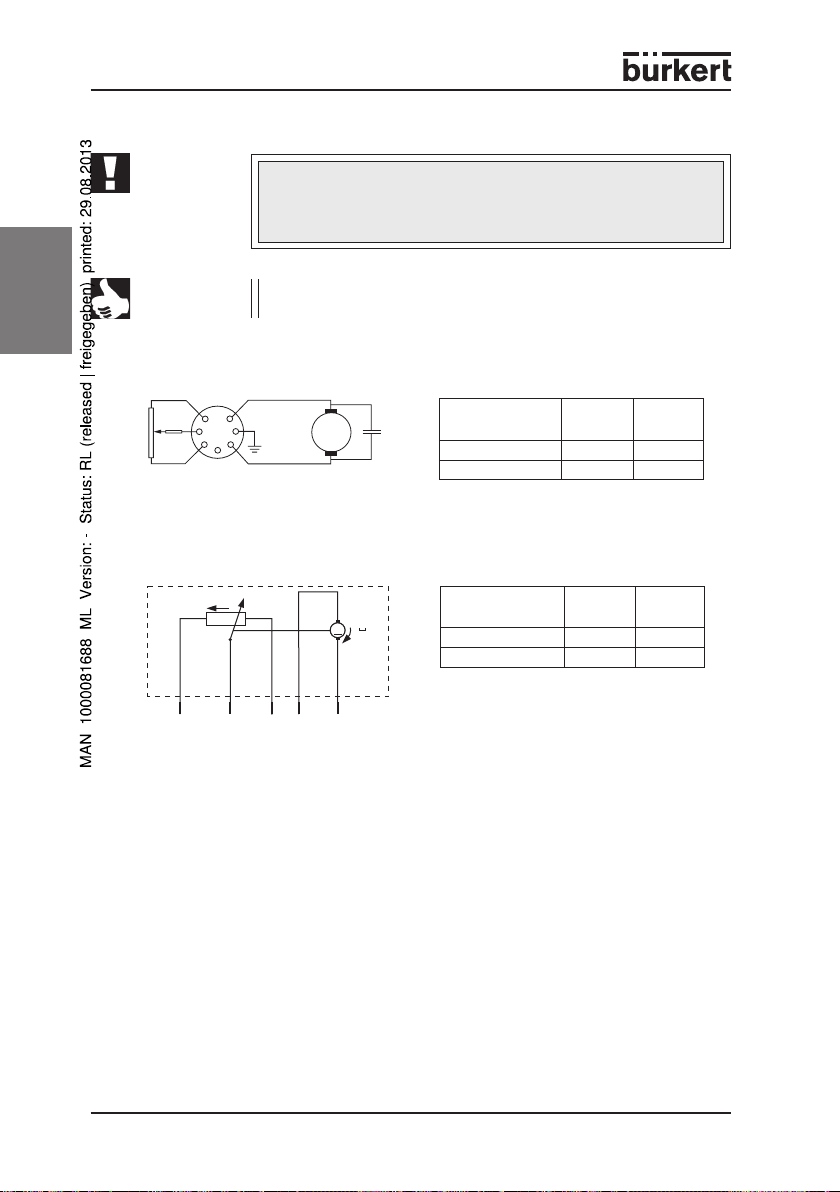
Electrical connections
ATTENTION!
NOTE
english
Plug configuration Mod
Rs = 6.8 kΩ
P1 = 1.0 kΩ / 5.0 kΩ
Plug configuration LC
P1
6
1
5
2
4
R
3
s
1234
The operating voltage and frequency of the electrical supply
must be the same as quoted on the rating plate of the drive.
The voltages and currents must not lie outside the permitted
operating range.
With a pulsed drive and nominal voltage, the pulse duration
should not fall below 100 ms.
PolePole
Pole
PolePole
M
configurationconfiguration
configuration
configurationconfiguration
left running plus minus
Pin 1Pin 1
Pin 1
Pin 1Pin 1
Pin 2Pin 2
Pin 2
Pin 2Pin 2
right running minus plus
PolePole
Pole
PolePole
configurationconfiguration
configuration
M
M
configurationconfiguration
left running minus plus
Pin 4Pin 4
Pin 4
Pin 4Pin 4
Pin 6Pin 6
Pin 6
Pin 6Pin 6
right running plus minus
65
P1 = 5.0 kΩ
14 - 0258
Page 17
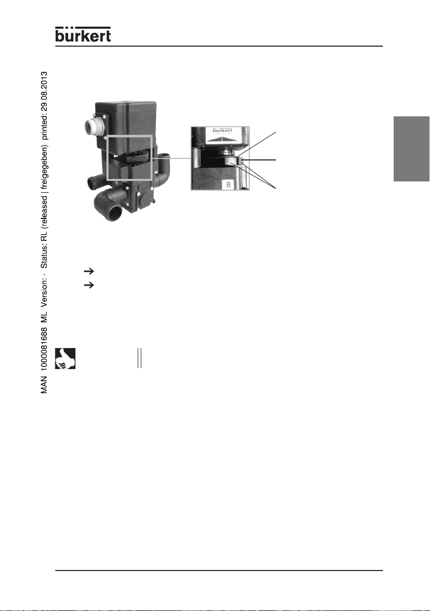
OPERATING AND DISPLAY ELEMENTS
Emergency manual override
Coupling bell, firmly
connected to the
drive
Button, separates
the drive from the
valve when pressed
in
Emergency manual
override, adjustable,
connected to the
rotatable valve
With the emergency manual override, you can adjust the valve regardless of
the position of the drive.
Press the button in (see illustration) to separate the drive from the valve.
Turn the emergency manual override into the desired position while holding
the button in.
If the drive is driven over the complete rotary range, the emergency manual
override latches in again in the neutral position.
english
NOTE
The position query generally takes place on the basis of the
drive position, and not on the position of the valve.
Optical position indicator
The optical position indicator results from the position of the emergency
manual override.
Turn the emergency manual override the the right: outlet port A closes and
outlet port B opens at the same time.
Turn the emergency manual override to the left, outlet port B closes and
outlet port A opens.
The transition is flowing.
0258 - 15
Page 18
PUTTING INTO OPERATION
Safety notes
ATTENTION!
english
Before putting the motorised control valve into operation,
ensure that
• the electrical power supply corresponds to the voltage
• the electrical connections have been carried out as
• the motorised regulating valve is only used in its original
• all hoses are securely connected to the hose
ASSEMBLY
NOTE
You can install the motor control valve in any position, but preferably with
the drive at the top.
Single blocks are secured with tie rods or angle brackets, and dual and quad
blocks with angle brackets.
If connection sizes or angled connections other than those set
up in the factory are required, the valve must be converted by
the factory. This also applies to changes to the serial
connection of the modules.
OPERATION AND FUNCTION
quoted on the rating plate,
described in the TECHNICAL DATA chapter.
configuration and must not be dismantled,
connections. Danger of scalding!
Safety notes
ATTENTION!
16 - 0258
Observe the following during operation
• compliance with the general technical rules!
• the valid accident prevention and safety regulations for
electrical device.
Page 19
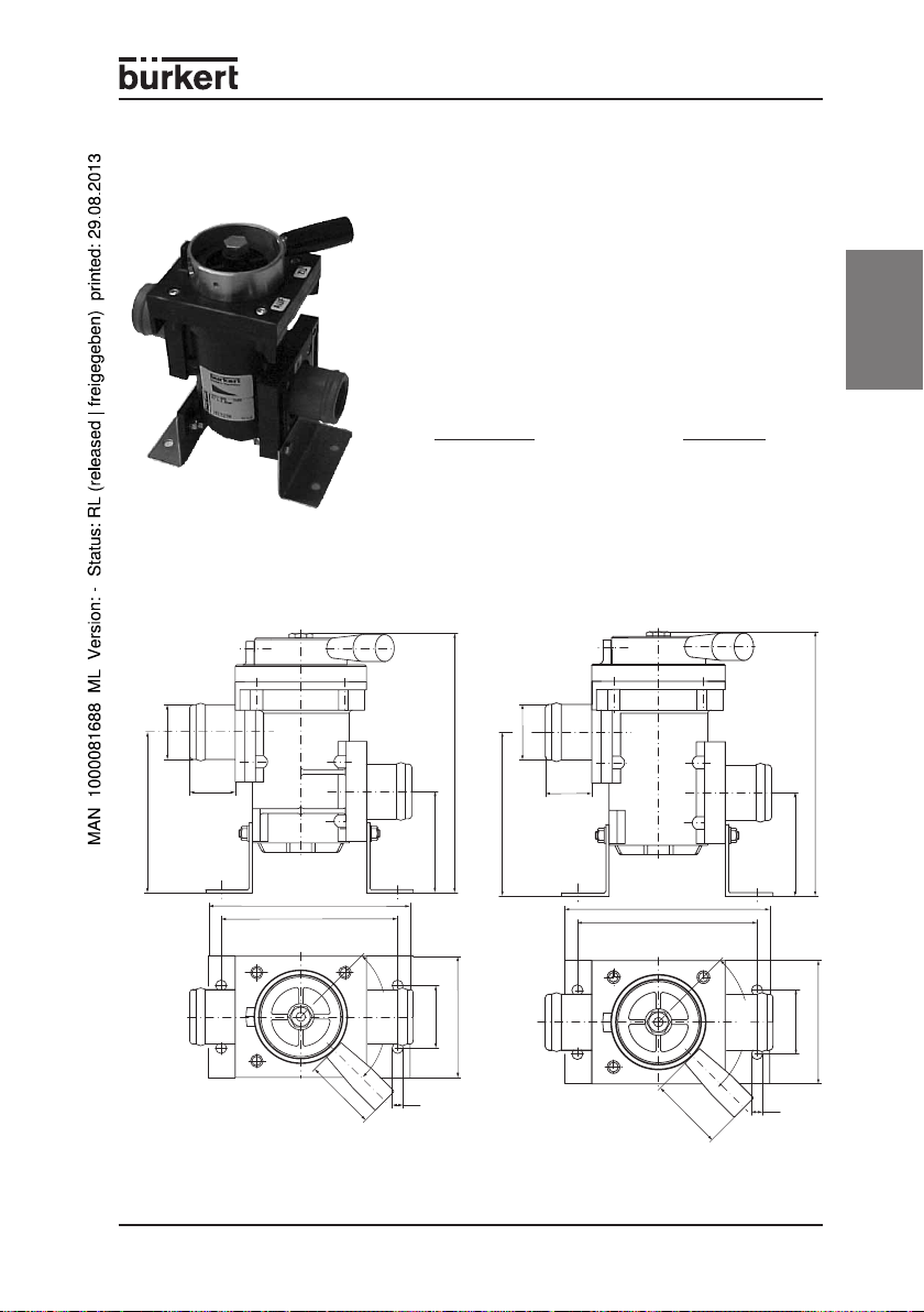
ACCESSORY
Modular filter type 250, solo
english
DescriptionDescription
Description
DescriptionDescription
Filter shut-off module 191 327
Filter magnet shut-off module 198 066
Dimensional drawings for modular filter type 250, solo
103
Ö35
P
DN 25
29
129
113
DN 25
Zu
Auf
A
°
90
(Stellbereich)
166
103
65
40
77,5
Ö35
P
DN
25
29
129
113
Order no.Order no.
Order no.
Order no.Order no.
A
DN
25
Zu
90° (Stell-
bereich)
Auf
166
65
40
77,5
46
Ö7
46
Ö7
0258 - 17
Page 20
3-way check valve block with shut-off valve
english
DescriptionDescription
Description
DescriptionDescription
Order no.Order no.
Order no.
Order no.Order no.
Check valve block with 192 218
shut-off cock
Dimensional drawings for 3-way check valve block with shut-off
valve
33
132
35
1.5
40
TU 28
238
Open
manual lever
Closed
TU 35
Ö7
18 - 0258
Page 21
MAINTENANCE
Safety notes
ATTENTION!
During maintenance and service work, ensure that:
• work on the devices may only be carried out by persons
who have been authorised and have received the
corresponding training.
• the devices must be switched free of electrical voltage
before the start of the maintenance work.
• the national regulations valid in the country of use are
complied with.
Service
Check the following within the context of the service work:
• that the lines are firmly seated,
• the plastic body for cracks and other visible damage,
• the maintenance of the permitted temperatures (see the TECHNICAL
DATA chapter),
• the proper functioning of the device.
Service intervals
Check the correct condition of the motorised control valve with regard to
assembly, installation, and operation at regular intervals.
Take the following factors into consideration when determining the inspection
intervals:
• Operating conditions (loading level, incorrect operation),
• The manufacturer's data in the technical documentation (mechanical and
electrical service life),
• Major changes in the system.
english
Correction of faults
If you detect faults that have an effect on the functionality of the motorised
control valve, these must be corrected immediately:
• Place the device out of operation, and switch it free of voltage!
• Correct the fault.
• Put the device back into operation.
0258 - 19
Page 22
TRANSPORT AND STORAGE
Transport and storage are only permitted in the original packaging.
DISPOSAL
NOTE
english
Observe the national regulations for the disposal of waste in
the respective country of use.
20 - 0258
Page 23

Modulares 2- und 3-Wege-
Motorregelventil
ALLGEMEINE HINWEISE......................................................................... 23
Darstellungsmittel .................................................................................. 23
Warenzeichen .........................................................................................23
Sicherheitshinweise .............................................................................. 23
Bestimmungsgemäßer Gebrauch....................................................... 24
Lieferumfang ........................................................................................... 24
Garantiebestimmungen ........................................................................ 24
Zulassung ................................................................................................ 25
SYSTEMBESCHREIBUNG...................................................................... 26
Einsatz ...................................................................................................... 26
Aufbau ...................................................................................................... 26
Funktion.................................................................................................... 26
Wirkungsweisen des Ventils ................................................................ 27
Durchfluss-Kennlinien ........................................................................... 27
Kennzeichnung ....................................................................................... 28
Grundmodule .......................................................................................... 29
Filtermodul ....................................................................................................... 29
2-Wege-Durchlassventil ................................................................................ 29
3-Wege-Misch- oder Verteilerventil ............................................................ 30
Rückschlagventil .............................................................................................. 30
Absperrventil ................................................................................................... 30
deutsch
TECHNISCHE DATEN ............................................................................... 31
Abmessungen ......................................................................................... 31
4fach Block ...................................................................................................... 31
Leitungsanschlüsse (Schlauch) ................................................................... 31
Allgemeine Daten ................................................................................... 32
Mechanische Daten .............................................................................. 32
Elektrische Daten ................................................................................... 33
Elektrische Anschlüsse ......................................................................... 34
Steckerbelegung Mod ................................................................................... 34
Steckerbelegung LC ...................................................................................... 34
BEDIEN- UND ANZEIGEELEMENTE..................................................... 35
Handnotbetätigung ................................................................................35
0258 - 21
Page 24

INBETRIEBNAHME .................................................................................... 36
BEDIENUNG UND FUNKTION................................................................ 36
ZUBEHÖR.................................................................................................... 37
deutsch
INSTANDHALTUNG.................................................................................... 39
TRANSPORT UND LAGERUNG ............................................................40
ENTSORGUNG .......................................................................................... 40
Optische Stellungsanzeige .................................................................. 35
Sicherheitshinweise .............................................................................. 36
Montage ................................................................................................... 36
Sicherheitshinweise .............................................................................. 36
Modularer Filter Typ 250, solo ............................................................ 37
Maßzeichnung Modularer Filter Typ 250, solo ................................ 37
3fach Rückschlagventilblock mit Absperrventil .............................. 38
Maßzeichnung 3fach Rückschlagventilblock
mit Absperrventil..................................................................................... 38
Sicherheitshinweise .............................................................................. 39
Wartung.................................................................................................... 39
Wartungsintervalle ................................................................................. 39
Beseitigung von Fehlern....................................................................... 39
22 - 0258
Page 25

ALLGEMEINE HINWEISE
Darstellungsmittel
In dieser Betriebsanleitung werden folgende Darstellungsmittel verwendet:
markiert einen Arbeitsschritt, den Sie ausführen müssen.
ACHTUNG!
HINWEIS
kennzeichnet Hinweise, bei deren Nichtbeachtung Ihre
Gesundheit oder die Funktionsfähigkeit des Gerätes
gefährdet ist.
kennzeichnet wichtige Zusatzinformationen,
Tipps und Empfehlungen.
Warenzeichen
Ultramid® ist ein geschütztes Warenzeichen der Firma BASF.
Grivory® ist ein geschütztes Warenzeichen der Firma EMS-Grivory.
Sicherheitshinweise
Bitte beachten Sie die Hinweise dieser Betriebsanleitung sowie die Einsatzbedingungen und zulässigen Daten, die im Datenblatt spezifiziert sind, damit
das Gerät einwandfrei funktioniert und lange einsatzfähig bleibt:
• Halten Sie sich bei der Einsatzplanung und dem Betrieb des Gerätes an
die allgemeinen Regeln der Technik!
• Verwenden Sie das Gerät bestimmungsgemäß nur für den mit der Fa.
Bürkert vereinbarten Einsatz.
• Installation und Wartungsarbeiten dürfen nur durch Fachpersonal und mit
geeignetem Werkzeug erfolgen!
• Beachten Sie die geltenden Unfallverhütungs- und Sicherheitsbestimmungen für elektrische Geräte während des Betriebs und der Wartung
des Gerätes!
• Schalten Sie vor Eingriffen in das System in jedem Fall die Spannung ab!
• Vermeiden Sie beim Einbau des Motorregelventils und beim Anschluss der
Leitungen an die Schlauchanschlüsse unzulässige mechanische Kräfte
und Spannungen.
• Treffen Sie geeignete Maßnahmen, um unbeabsichtigtes Betätigen oder
unzulässige Beeinträchtigung auszuschließen!
• Verwenden Sie das Gerät nur in seiner Originalkonfiguration!
• Bei Nichtbeachtung dieser Hinweise und unzulässigen Eingriffen in das
Gerät entfällt jegliche Haftung unsererseits, ebenso erlischt die Garantie
auf Geräte und Zubehörteile!
deutsch
0258 - 23
Page 26

Bestimmungsgemäßer Gebrauch
Das modulare 2- und 3-Wege-Motorregelventil vom Typ 0258 ist vorzugsweise als Stellglied für Heizwasser- oder Kühlmittelkreisläufe in Omnibussen,
Nutz-, Schwimm- und Schienenfahrzeugen sowie im Werkzeugmaschinenbau
einsetzbar. Die für Ihren speziellen Anwendungsfall erforderliche Konfiguration wird von unseren Mitarbeitern im Außendienst zusammengestellt. Verwenden Sie das modulare 2- und 3-Wege-Motorregelventil vom Typ 0258 nur für
diesen mit der Fa. Bürkert vereinbarten Anwendungsfall. Eine anderweitige
Verwendung muss mit dem Kundenservice der Fa. Bürkert abgesprochen
werden.
Lieferumfang
Überzeugen Sie sich unmittelbar nach Erhalt der Sendung, dass der Inhalt
nicht beschädigt ist und mit dem auf dem beigelegten Packzettel angegebenen Lieferumfang übereinstimmt.
deutsch
Bei Unstimmigkeiten wenden Sie sich bitte umgehend an unser Call-Center:
oder an Ihr Bürkert Vertriebs-Center.
Bürkert Fluid Control Systems
Call-Center
Chr.-Bürkert-Str. 13-17
D-76453 Ingelfingen
Tel. : 07940-10111
Fax: 07940-10448
E-mail: info@de.buerkert.com
Garantiebestimmungen
Diese Druckschrift enthält keine Garantiezusagen. Wir verweisen hierzu auf
unsere allgemeinen Verkaufs- und Geschäftsbedingungen. Voraussetzung für
die Garantie ist der bestimmungsgemäße Gebrauch des Gerätes unter Beachtung der spezifizierten Einsatzbedingungen.
ACHTUNG!
24 - 0258
Die Gewährleistung erstreckt sich nur auf die Fehlerfreiheit
des Motorregelventils und seiner Bauteile.
Es wird jedoch keine Haftung übernommen für Folgeschäden jeglicher Art, die durch Ausfall oder Fehlfunktion des
Gerätes entstehen könnten.
Page 27

Zulassung
Geräte, die das Typgenehmigungszeichen tragen müssen, wurden beim Kraftfahrtbundesamt unter der Typgenehmigungsnummer
e1*72/245*95/54*3187*00
genehmigt und werden mit dem gezeigten Typgenehmigungzeichen in den
Verkehr gebracht.
1
e
023187
Einen Auszug der Typgenehmigung erhalten Sie unter der unten stehenden
Adresse.
Bürkert Werke GmbH & Co KG
Zulassungsbeauftragter
Christian Bürkert Str.13-17
74653 Ingelfingen
deutsch
0258 - 25
Page 28

SYSTEMBESCHREIBUNG
Einsatz
Das modulare 2- und 3-Wege-Motorregelventil vom Typ 0258 ist vorzugsweise als Stellglied für Heizwasser- oder Kühlmittelkreisläufe in Omnibussen, Nutz-, Schwimm- und Schienenfahrzeugen sowie im Werkzeugmaschinenbau einsetzbar.
Aufbau
deutsch
(optische Stellungsanzeige)
Das Motorregelventil Typ 0258 ist modular aufgebaut und wird einzeln oder
zu Blöcken angereiht montiert. In einem Block sind bis zu 4 Ventile
kombinierbar. Es kann wahlweise als 2- oder 3-Wege-Ventil eingesetzt
werden. Es enthält keramische Dichtelemente, das Ventilgehäuse besteht
aus Kunststoff.
Der eingesetzte elektrische Drehantrieb mit Gleichspannungsmotor besteht
entweder aus einem wartungsfreien Flachantrieb1) (LC) mit AMP-Stecker
oder aus einem wartungsfreien, leistungsstärkeren Stirnradantrieb2) (Mod)
mit Magnetkupplung und Hirschmann-Stecker (Optionen möglich), einer
Handnotbetätigung mit optischer Stellungsanzeige und einem oder mehreren
Ventilmodulen.
Die Antriebe haben in Verbindung mit der Handnotbetätigung einen Stellwinkel von 180°. Die Antriebe dürfen ohne Handnotbetätigung nicht betrieben werden, da sonst der Stellungsrückmelder dejustiert werden kann.
1)
2)
elektrischer Anschluss
(AMP oder Rundstecker
nach DIN 43651,
Hirschmann)
Handnotbetätigung
Flachantrieb (LC): im folgenden Text immer "LC"
Stirnradantrieb (Mod): im folgenden Text immer "Mod"
Motorantrieb leistungsstarker Stirnradantrieb mit Magnetkupplung
(Mod) oder Flachantrieb
(LC), jeweils mit Stellungsrückmeldung
Ventilmodul
Funktion
Der Antrieb bewegt über eine Welle eine Regelscheibe über eine Fixscheibe
aus Oxyd-Keramik und verschließt somit die Ventilsitze A und B wechselseitig
bei gleitendem Übergang.
In Abhängigkeit vom Stellwinkel sind die Durchflusswerte (2 Wege), Mischoder Verteilungsverhältnisse (3 Wege) stetig veränderbar.
Die Stellungsrückmeldung erfolgt über ein Potentiometer.
26 - 0258
Page 29

Wirkungsweisen des Ventils
Wirkungsweise I
A
2-Wege-Ventil zur stetigen Steuerung des Durchflusses
M
im Ausgang A,
motorgetrieben, stromlos verharrend
P
Wirkungsweise E
P
3-Wege-Ventil zur stetigen Mischung der Zuströme A und B
M
auf den Anschluss P,
motorgetrieben, stromlos verharrend
A B
Wirkungsweise F
B
A
3-Wege-Ventil zur stetigen Verteilung des Zustromes P
M
auf die Ausgänge A und B,
motorgetrieben, stromlos verharrend
P
Durchfluss-Kennlinien
Die Durchfluss1)-Kennlinien für die Kv-Sollwerte von 3 m3 und 6 m3 sind in
den folgenden Diagrammen dargestellt. Der Kv-Sollwert von 1 m 3 ist in Vorbereitung.
Durchflusskennlinie2) Kv-Sollwert = 3 m
3
deutsch
/h]
3
Kv-Wert [m
Potentiometer3) [%]
1)
Durchfluss: Kv-Wert Wasser [m³/h],
Ausgang.
2)
nur Antriebsart Mod
3 )
relativiert auf den Gesamthub des Potentiometers = 100 %
4 )
Druckangabe in [bar]: Überdruck zum Atmosphärendruck
Messung bei +20 °C, 1 bar
4 )
Druck am Ventileingang und freiem
0258 - 27
Page 30

Durchflusskennlinie1) Kv-Sollwert = 6 m
6
6
/h]
3
5
5
4
4
3
3
Kv-Wert [m
2
2
1
1
0
0
0
9
0
9
33
33
21
21
Potentiometer2) [%]
1)
nur Antriebsart Mod
2)
relativiert auf den Gesamthub des Potentiometers = 100 %
Kennzeichnung
3
45
57 70 82 94
45
57 70 82 94
deutsch
Das Motorregelventil ist durch zwei Typenschilder gekennzeichnet.
Das Typenschild für das Komplettgerät (Ventilblock) befindet sich unten auf
der linken Seite. Es bezeichnet in der oberen Zeile den Geräteschlüssel
"SYST-0258", in der unteren Zeile die Identnummer sowie das verschlüsselte
Baudatum.
Jeder Antrieb verfügt außerdem über ein eigenes Typenschild mit folgendem
Inhalt:
• Geräteschlüssel/ZeichNr. z. B.: 0258-G665-205-00,
• Spannung und Spannungsart: 24 V DC,
• Aufnahmeleistung: z. B. 3 W,
• Drehwinkel: z. B.: 28 s / 180°,
• Nenndruck: z. B.: 0 ... 2,5 bar,
• Identnummer und verschlüsseltes Baudatum.
28 - 0258
Page 31

Grundmodule
4
2
1
3
Alle Grundmodule können Sie einzeln oder im Block einsetzen.
Filtermodul
Handhebel
Beschreibung
Das Filtermodul kann von Hand abgesperrt werden. Beachten Sie die
Durchflussrichtung.
Optional kann das Filtermodul mit
einem Magneteinsatz ausgerüstet sein.
Blocksymbol
2-Wege-Durchlassventil
4
Beschreibung
Das 2-Wege-Durchlassventil ist
stetigwirkend.
Die Durchflussrichtung:
P A, P B
Blocksymbol
2
deutsch
0258 - 29
Page 32

3-Wege-Misch- oder Verteilerventil
deutsch
Rückschlagventil
Beschreibung
Das 3-Wege-Misch- oder Verteilerventil ist stetigwirkend.
Die Durchflussrichtungen
• im Verteilerventil: P A, P B
• im Mischventil: P1 A, P2 A
Blocksymbole
1
4
2
E
3
1
4
2
F
3
Mischen Verteilen
Beschreibung
Das Rückschlagventil hat
Sammelfunktion. Handbetätigung ist
möglich. Handhebel in Linksanschlag:
P A geschlossen
P B offen
Beachten Sie die Durchflussrichtung.
Blocksymbol
1
4
R
2
3
Absperrventil
30 - 0258
Befestigungswinkel
Handhebel
Beschreibung
Das Absperrventil wird von Hand betätigt. Die Durchflussrichtung ist beliebig.
Blocksymbol
4
2
Page 33

TECHNISCHE DATEN
Abmessungen
4fach Block
Ø29,8
Ø36,5
Ø34,5
Ø27,8
TU35
37,6
35,6
TU28
Ø23,4
35,6
Ø
TU22
21,8
Abschlussplatte
19
12
25,7
11,44
14,5
57
TU35
52,5
Ø 34,5
Ø 36,5
51,85
8,88
38,5
1,5
10,5
49,1
TU28
47
259,5
Ø 27,8
276
Ø 29,8
Leitungsanschlüsse
Schlauchanschluss, gerade
BezeichnungBezeichnung
Bezeichnung
BezeichnungBezeichnung
TU22L 22 47,5
TU28L 28 50,5
TU35L 35 53,85
DurchmesserDurchmesser
Durchmesser
DurchmesserDurchmesser
(mm)(mm)
(mm)
(mm)(mm)
TU22
44
37
14,5
58,2
deutsch
70,1
46,1
63
Ø21,8
35,2
Ø23,8
34,5
56
40
7
14,44
180,7
105,2
118,2
Diese Zusammenstellungs-
( 180,7 )
zeichnug ist eine Übersicht
über die verschiedenen
konstruktiven Möglichkei-
30
4
25,5
BauhöheBauhöhe
Bauhöhe
BauhöheBauhöhe
(mm)(mm)
(mm)
(mm)(mm)
6,4
38,5
1,5
46
ten des Motorregelventils.
Schlauchanschluss, abgewinkelt
BezeichnungBezeichnung
Bezeichnung
BezeichnungBezeichnung
DurchmesserDurchmesser
Durchmesser
DurchmesserDurchmesser
(mm)(mm)
(mm)
(mm)(mm)
TU22 22 37
TU28 28 37
TU35 35 39
BauhöheBauhöhe
Bauhöhe
BauhöheBauhöhe
(mm)(mm)
(mm)
(mm)(mm)
0258 - 31
Page 34

Allgemeine Daten
Umgebungstemperatur -20 ... +80 °C
Betriebstemperatur -20 ... +95 °C
Lagertemperatur 0 ... +60 °C
rel. Luftfeuchte max. 80 %
Gewicht ca. 900 g / Modul, abhängig von der Ausführung
Nennbetriebsart
Schutzart IP 65
Zulassung Typgenehmigung beim Kraftfahrtbundesamt
Mechanische Daten
deutsch
Werkstoffe
Ventilgehäuse Ultramid® T KR 4355 G5 schwarz,
Ventilinnenteile Ultramid® T KR 4355 G5 schwarz,
Dichtwerkstoff FKM / Al2O3
Medien
Medientemperatur -20 ... +95 °C
Viskosität max. 40 mm²/s
Leitungsanschluss Schlauchanschlüsse,
Motordrehmoment LC nom./max.: 0,35 Nm / 0,7 Nm
Blockaufbau mit Klemmblechen und Zwischenadaptern
Befestigung mit Haltewinkeln und Zugstangen
Einbaulage beliebig, vorzugsweise Antrieb nach oben
Grundmodule 2- und 3-Wege-Ventile
1) 2)
3)
Dauerbetrieb ED 100 %
e1*72/245*95/54*3187*00
Grivory® HTV schwarz
Grivory® HTV schwarz und VA
neutrale Gase und Flüssigkeiten, z. B. Luft,
Wasser, Glykole, Kühlwasser mit Additiven
wahlweise TU 22, TU28, TU35,
gerade oder gewinkelt
Mod. nom./max.: 1,2 Nm / 2,1 Nm
Rückschlagventil
Filtermodul, absperrbar
Hand-Absperrventil
4)
32 - 0258
Page 35

Elektrische Daten
Stellrichtung je nach Polarität und Antriebstyp
Stellzeit für 100 %
Elektrischer Anschluss LC: für AMP-Buchse 967066-1
Stellungsrückmelder LC: 5 kΩ lin
Widerstandsänderung ca. 55 ... 75 % (bei 100 % Stellweg)
Potentiometer
max. Schleifstrom Standardausführung:
Potentiometer Leitplast-Ausführung:
max. Spannung LC: 7,5 V (Potentiometer-Klemmen 1 und 3)
Potentiometer Mod: 10 V (Potentiometer-Klemmen 4 und 6)
max. Leistung LC: 0,25 W / 40 °C
Potentiometer
Nennbetriebs
spannung
))
9
)
))
Spannungstoleranz ±10 %
Leistungsaufnahme LC: 4,8 W
5)
LC: ca. 4 ... 8 s bei 24 V DC
Mod: ca. 28 s bei 24 V DC
und AMP-Kontakt 962885-1
Mod: Rundstecker nach DIN 43651
(6polig und Masse)
Mod: Potentiometer 1 kΩ lin (optional 5 kΩ lin
sowie Leitplast-Ausführungen)
Schutzwiderstand Rs = 6,8 kΩ
8)
--
- 24 V DC
--
Mod: 0,5 W / 40 °C
Mod: 3 W
≤≤
≤4 mA
≤≤
≤≤
≤65 µA
≤≤
7)
6)
deutsch
HINWEIS
LC: Max. Anzahl der Ansteuerungen (bei Nominaldrehmo-
ment) = 100 000 unter Laborbedingungen, 20 °C und je
1 s Ansteuerzeit durch den gesamten Stellbereich.
Mod: Max. Anzahl der Ansteuerungen = 400 000 unter Laborbedingungen, 20 °C und je 1 s Ansteuerzeit durch den gesamten Stellbereich.
1 )
Pausenzeit bei Drehumkehr 0,4 s.
2 )
Bei permanenter Ansteuerung des Motors erhöhter Verschleiss.
3 )
eingeschränkte Gasdichtheit
4 )
Verschmutzungen (z. B. Flusen usw.) sollten vorgefiltert werden, sonst eventuell Beeinträchtigung der
Ventilfunktion.
5 )
Bei 24 V DC geglättet. Gepulste Ansteuerung verlängert die Stellzeit (siehe auch 9) )
6 )
abhängig vom Druck/Last
7 )
Höhere Ströme schränken die Lebensdauer stark ein!
8 )
Höhere Temperaturen schränken die max. Verlustleistung des Potentiometers ein.
9 )
min. Pulsdauer (im Leerlauf / bei Druck/Last erhöht sich die min. Pulsdauer):
bei LC: ca. 100 ms / bei Mod.: ca. 100 ms
0258 - 33
Page 36

Elektrische Anschlüsse
ACHTUNG!
HINWEIS
Steckerbelegung Mod
deutsch
Rs = 6,8 kΩ
P1 = 1,0 kΩ / 5,0 kΩ
Steckerbelegung LC
P1
6
1
5
2
4
R
3
s
1234
Die Betriebsspannung und Frequenz der Versorgung müssen
mit den Typschildangaben des Antriebs überein stimmen.
Die Spannungen und Ströme dürfen nicht außerhalb des
zulässigen Betriebsbereichs liegen.
Bei getaktetem Antrieb und Nennspannung soll die Impulsdauer von 100 ms nicht unterschritten werden.
M
65
PolbelegungPolbelegung
Polbelegung
PolbelegungPolbelegung
Linkslauf plus minus
Rechtslauf minus plus
PolbelegungPolbelegung
Polbelegung
PolbelegungPolbelegung
M
M
Linkslauf minus plus
Rechtslauf plus minus
Pin 1Pin 1
Pin 1
Pin 1Pin 1
Pin 4Pin 4
Pin 4
Pin 4Pin 4
Pin 2Pin 2
Pin 2
Pin 2Pin 2
Pin 6Pin 6
Pin 6
Pin 6Pin 6
P1 = 5,0 kΩ
34 - 0258
Page 37

BEDIEN- UND ANZEIGEELEMENTE
Handnotbetätigung
Kupplungsglocke,
fest mit dem Antrieb
verbunden
Taste, trennt durch
Eindrücken den
Antrieb vom Ventil
Handnotbetätigung,
verstellbar, mit dem
verdrehbaren Ventil
verbunden
Mit der Handnotbetätigung verstellen Sie das Ventil unabhängig von der
Antriebsstellung.
Drücken Sie die Taste (siehe Abbildung) ein, um den Antrieb vom Ventil
zu trennen.
Drehen Sie die Handnotbetätigung mit eingedrückter Taste in die
gewünschte Position.
Wird der Antrieb über den gesamten Stellbereich verfahren, rastet die Handnotbetätigung wieder in Neutralstellung ein.
HINWEIS
Die Positionsabfrage erfolgt generell anhand der Antriebsstellung und nicht nach der Stellung des Ventils.
Optische Stellungsanzeige
Die optische Stellungsanzeige resultiert aus der Lage der Handnotbetätigung.
Drehen Sie die Handnotbetätigung nach rechts, schließt sich Ausgang A und
Ausgang B wird gleichzeitig geöffnet.
Drehen Sie die Handnotbetätigung nach links, schließt sich Ausgang B und
Ausgang A wird geöffnet.
Der Übergang ist fließend.
deutsch
0258 - 35
Page 38

INBETRIEBNAHME
Sicherheitshinweise
ACHTUNG!
deutsch
Montage
HINWEIS Sind andere als die vom Werk eingestellten Anschlussgrößen
Einfach-Blöcke werden durch Zugstangen oder Winkel, 2fach- bis 4fachBlöcke durch Winkel befestigt.
Das Motorregelventil können Sie in beliebiger Lage einbauen, bevorzugt
vertikal mit Antrieb nach oben.
Beachten Sie vor der Inbetriebnahme des Motorregelventils, dass
• die Stromversorgungsspannung der auf dem Typenschild
angegebenen Spannung entsprechen muss,
• die elektrischen Anschlüsse wie in Kap. TECHNISCHE
DATEN ausgeführt werden müssen,
• das Motorregelventil nur in seiner Originalkonfiguration
verwendet und nicht demontiert werden darf,
• alle Schläuche sicher mit den Schlauchanschlüssen
verbunden sind. Verbrühungsgefahr!
oder Anschlusswinkelstellungen erforderlich, muss das Ventil
vom Werk umgebaut werden. Das betrifft auch Änderungen an
der Anreihung der Module.
BEDIENUNG UND FUNKTION
Sicherheitshinweise
ACHTUNG!
36 - 0258
Beachten Sie bei der Bedienung und im Betrieb
• die Einhaltung der allgemeinen Regeln der Technik!
• die geltenden Unfallverhütungs- und Sicherheitsbestimmungen für elektrische Geräte.
Page 39

ZUBEHÖR
Modularer Filter Typ 250, solo
BezeichnungBezeichnung
Bezeichnung
BezeichnungBezeichnung
Filter-Absperrmodul 191 327
Filter Magnet Absperrmodul 198 066
Maßzeichnungen Modularer Filter Typ 250, solo
Ö35
P
DN
25
29
103
Ö35
P
DN 25
29
129
113
A
DN 25
Zu
°
90
(Stellbereich)
Auf
46
166
103
65
40
77,5
Ö7
Bestell-Nr.Bestell-Nr.
Bestell-Nr.
Bestell-Nr.Bestell-Nr.
129
113
46
Zu
Auf
A
DN
25
90° (Stell-
bereich)
Ö7
deutsch
166
65
40
77,5
0258 - 37
Page 40

3fach Rückschlagventilblock mit Absperrventil
BezeichnungBezeichnung
Bezeichnung
BezeichnungBezeichnung
Rückschlagblock mit Ab- 192 218
sperrhahn
deutsch
Maßzeichnung 3fach Rückschlagventilblock mit Absperrventil
33
132
35
1,5
40
TU 28
238
Handhebel
ZU
AUF
TU 35
Ö7
Bestell-Nr.Bestell-Nr.
Bestell-Nr.
Bestell-Nr.Bestell-Nr.
38 - 0258
Page 41

INSTANDHALTUNG
Sicherheitshinweise
ACHTUNG!
Beachten Sie bei der Instandhaltung und Wartung, dass
• die Arbeiten an den Geräten nur von dazu befugtem und
entsprechend geschultem Personal durchgeführt werden
dürfen.
• die Geräte vor Beginn der Wartungsarbeiten spannungsfrei zu schalten sind.
• die geltenden nationalen Bestimmungen im Einsatzland
eingehalten werden müssen.
Wartung
Überprüfen Sie im Rahmen der Wartung:
• die Leitungen auf festen Sitz,
• das Kunststoffgehäuse auf Rissbildung und andere sichtbare Schäden,
• die Einhaltung der zulässigen Temperaturen (siehe Kap. TECHNISCHE
DATEN),
• die bestimmungsgemäße Funktion.
Wartungsintervalle
Prüfen Sie die Motorregelventile auf ihren ordnungsgemäßen Zustand hinsichtlich der Montage, der Installation und des Betriebes regelmäßig.
Berücksichtigen Sie die folgenden Faktoren bei der Festlegung der Prüfintervalle:
• Betriebsbedingungen (Auslastungsgrad, Fehlbedienung),
• Herstellerangaben in der technischen Dokumentation (mechanische und
elektrische Lebensdauer),
• größere Veränderung im System.
deutsch
Beseitigung von Fehlern
Haben Sie Fehler festgestellt, die sich auf die Funktionsfähigkeit des Motorregelventils auswirken, müssen diese sofort beseitigt werden:
• Setzen Sie das Gerät außer Betrieb, schalten Sie es spannungsfrei!
• Beseitigen Sie den Fehler.
• Nehmen Sie das Gerät wieder in Betrieb.
0258 - 39
Page 42

TRANSPORT UND LAGERUNG
Transport und Lagerung sind nur in Originalverpackung gestattet.
ENTSORGUNG
HINWEIS
deutsch
Beachten Sie die nationalen Vorschriften zur Abfallentsorgung im jeweiligen Einsatzland.
40 - 0258
Page 43

Vanne de régulation motorisée
modulaire à 2 et 3 voies
IDENTIFICATIONS GENERALES ........................................................... 43
Symboles utilisès ................................................................................... 43
Marque déposée .................................................................................... 43
Consignes de sécurité .......................................................................... 43
Utilisation conforme aux instructions ................................................ 44
Fourniture ................................................................................................. 44
Clauses de garantie ..............................................................................44
Homologation .......................................................................................... 45
DESCRIPTION DU SYSTEME ................................................................. 46
Mise en oeuvre ....................................................................................... 46
Construction ........................................................................................... 46
Fonctionnement...................................................................................... 46
Mode d'action de la vanne .................................................................. 47
Courbes caractéristiques de débit ..................................................... 47
Marquage ................................................................................................. 48
Modules de base.................................................................................... 49
Module filtrant.................................................................................................. 49
Vanne d'admission à 2 voies ........................................................................ 49
Vanne de mélange ou de répartition à 3 voies ......................................... 50
Clapet antiretour ............................................................................................ 50
Vanne d'arrêt .................................................................................................... 50
français
CARACTERISTIQUES TECHNIQUES .................................................. 51
Dimensions .............................................................................................. 51
Bloc quadruple ................................................................................................ 51
Raccords de conduites (tuyau) .................................................................. 51
Caractéristiques générales .................................................................. 52
Caractéristiques mécaniques ............................................................. 52
Caractéristiques électriques ............................................................... 53
Branchements électriques ...................................................................54
Affectation des connecteurs Mod .............................................................. 54
Affectation des connecteurs LC ................................................................. 54
ORGANES DE COMMANDE ET D'AFFICHAGE ...............................55
Commande de secours manuelle....................................................... 55
0258 - 41
Page 44

MISE EN SERVICE .................................................................................... 56
COMMANDE ET FONCTIONNEMENT................................................. 56
ACCESSOIRES ......................................................................................... 57
MAINTENANCE ........................................................................................... 59
français
TRANSPORT ET STOCKAGE ................................................................60
MISE AU REBUT ........................................................................................ 60
Affichage de position optique ............................................................. 55
Consignes de sécurité .......................................................................... 56
Montage ................................................................................................... 56
Consignes de sécurité .......................................................................... 56
Filtre modulaire type 250, solo ........................................................... 57
Dessins dimensionnels du filtre modulaire type 250, solo ........... 57
Bloc de 3 clapets antiretour avec robinet d'arrêt........................... 58
Dessin dimensionnel du bloc de 3 clapets antiretour
avec robinet d'arrêt ................................................................................ 58
Consignes de sécurité .......................................................................... 59
Entretien................................................................................................... 59
Intervalle d'éntretien ..............................................................................59
Elimination des défauts ........................................................................ 59
42 - 0258
Page 45

INDICATIONS GENERALES
Symboles utilisés
Les symboles utilisés dans cette notice d'instructions sont les suivants:
désigne une opération à exécuter.
ATTENTION!
REMARQUE
désigne une mise en garde dont l'inobservation pourrait
mettre en danger votre santé ou l'intégrité de l'appareil.
désigne des informations supplémentaires, conseils et
recommandations importantes.
Marque déposée
Ultramid® est une marque déposée de la société BASF.
Grivory® est une marque déposée de la société EMS-Grivory.
Consignes de sécurité
Veuillez tenir compte des directives figurant dans ces instructions de service
de même que des conditions d'utilisation et des données autorisées
spécifiées dans la fiche technique pour que l'appareil fonctionne parfaitement
et reste longtemps opérationnel:
• S'en tenir lors de la mise en oeuvre prévue et du service de l'appareil aux
règles techniques générales reconnues!
• Utiliser uniquement l'appareil conformément à sa destination pour les
inserts convenus de la maison Bürkert..
• L'installation et les interventions nécessitées par la maintenance ne
doivent être effectuées que par un personnel qualifié équipé des outils
adéquats!
• Respecter les dispositions en vigueur de prévention des accidents et de
sécurité pour appareils électriques pendant le service, la maintenance de
l'appareil!
• Toujours couper la tension d'allimentation avant toute intervention dans le
systeme!
• Eviter lors du montage de la vanne motorisée et lors du branchement des
conduites aux raccords des tuyaux souples des forces et tension
mécaniques non admises.
• Prendre les mesures qui s'imposent pour éviter un actionnement par
inadvertance de l'appareil ou une mise en cause inadmissible de son
fonctionnement!
• N'utiliser l'appareil que dans sa configuration originale!
• Nous déclinons toute responsabilité en cas d'inobservation des ces
recommandations et d'intervention non autorisée à l'intérieur de l'appareil.
Il en résulterait par ailleurs l'extinction de la garantie sur l'appareil et les
accessoires!
français
0258 - 43
Page 46

Utilisation conforme aux instructions
La vanne modulaire de régulation motorisée de type 0258 est mise en oeuvre
de préférence comme composant de réglage pour circuits d'eau chaude ou
de réfrigérant dans des omnibus, véhicules utilitaires, flottants et sur rails de
même que dans la construction de machines-outils.
La configuration nécessaire à votre application spéciale sera assemblée par
nos collaborateurs du service de visite à la clientèle. Utiliser uniquement la
vanne de régulation motorisée modulaire à 2 et 3 voies du type 0258 pour le
cas d'application convenu avec la maison Bürkert. Une autre emploi doit être
convenu avec le service après-vente de la maison Bürkert.
Fourniture
S'assurer immédiatement après réception de la fourniture si le contenu est
conforme à ce qui a été indiqué.
En cas de désaccord, veuillez contacter au plus vite notre centre d'appel:
Bürkert Fluid Control Systems
Chr.-Bürkert-Str. 13-17
français
ou votre revendeur Bürkert.
E-mail: info@de.buerkert.com
Centre d'appel
D-76453 Ingelfingen
Tel. : 07940-10111
Fax: 07940-10448
Clauses de garantie
Ce document ne constitue aucun assentiment de garantie. Nous vous
renvoyons à cet effet à nos conditions générales de vente et commerciales.
La condition préalable au consentement de la garantie est l'utilisation
conforme de l'appareil à l'usage auquel il est destiné, compte tenu de
l'observation des conditions d'emploi spécifiées.
ATTENTION!
44 - 0258
La garantie ne s'étend que jusqu'à l'absence de défaut de la
vanne de régulation motorisée et de ses composants.
Nous déclinons, par contre, toute responsabilité pour des
dégâts consécutifs de toute nature susceptibles de survenir
par suite de défaillance ou défaut de fonctionnement de
l'appareil.
Page 47

Homologation
Les appareils portant la marque e1 ont été homologués au Service fédéral de
la circulation automobile (Kraftfahrtbundesamt) sous le numéro
e1*72/245*95/54*3187*00
et seront mis en circulation avec la marque d'homologation indiquée.
1
e
023187
Vous recevrez un extrait de l'homologation à l'adresse ci-dessous:
Bürkert Werke GmbH & Co KG
Zulassungsbeauftragter
Christian Bürkert Str.13-17
74653 Ingelfingen
français
0258 - 45
Page 48

DESCRIPTION DU SYSTEME
Mise en oeuvre
La vanne modulaire de régulation motorisée de type 0258 est mise en oeuvre
de préférence comme composant de réglage pour circuits d'eau chaude ou
de réfrigérant dans des omnibus, véhicules utilitaires, flottants et sur rails de
même que dans la construction de machines-outils.
Construction
Branchement électrique
(AMP ou connecteur
rond selon DIN 43651,
Commande de secours
(indication optique de position)
français
Le vanne de régulation motorisée de type 0258 est de construction modulaire
et se monte, isolée ou rangée en bloc. Dans un bloc, jusqu'à 4 vannes
peuvent être combinées. On peut utiliser au choix des vannes à 2 ou 3 voies.
Il contient des éléments d'étanchéité en céramique, le corps de soupape est
en matière plastique.
L'entraînement rotatif électrique utilisé, à moteur à courant continu, est
constitué soit d'un entraîtement plat sans entretien1) (LC) à connecteur AMP,
soit d'un entraînement puissant à roue droite, sans entretien2) (Mod), à
accouplement magnétique et connecteur Hirschmann (options possibles),
commande de secours manuelle à indication optique de position et un
plusieurs modules de soupapes.
En liaison avec la commande de secours manuelle, les entraînements ont un
angle de positionnement de 180°. Les entraînements ne doivent pas être
utilisés sans commande de secours manuelle, car les dispositifs de réponse
seraient sinon déréglés.
1)
Entraînement plat (LC): ci-après toujours "LC"
2)
Entraînement à roue droite (Mod): ci-après toujours "Mod"
Fonctionnement
Hirschmann)
manuelle
Entraînement par moteur entraînement puissant à
roue droite avec
accouplement magnétique
(Mod) ou entraînement plat
(LC), chacun avec réponse
de position
Vanne modulaire
Par l'intermédiaire d'un axe, l'entraînement déplace un disque de réglage
au-dessus d'un disque fixe en céramique oxydée et ferme ainsi alternativement les sièges de soupape A et B en transistion glissante.
En fonction de l'angle de réglage, les valeurs de débit (2 voies), les rapports
de mélange ou de répartition (3 voies) peuvent constamment être changés.
La réponse de position a lieu par un potentiomètre.
46 - 0258
Page 49

Mode d'action de la vanne
Mode d'action I
A
Vanne à 2 voies pour commande constante du débit
M
dans la sortie A,
motorisée, restant dans le même état sans courant
P
Mode d'action E
P
Vanne à 3 voies pour le mélange constant des courants
M
d'amenée A et B au raccord P,
motorisée, restant dans le même état sans courant
A B
Mode d'action F
B
A
Vanne à 3 voies pour la répartition constante de courants
M
d'amenée P aux sorties A et B,
motorisée, restant dans le même état sans courant
P
Courbes caractéristiques de débit
Les courbes de débit1) des valeurs de consignes Kv de 3 m3 et de 6 m3 sont
représentées dans les diagrammes suivants. La valeur de consigne de 1 m
est en préparation:
Courbe caractéristique de débit
2)
de la valeur de consigne Kv = 3 m
3
français
3
/h]
3
Valeur Kv [m
Poatentiomètre3) [%]
1)
Débit valeur Kv eau [m³/h],
2)
uniquement entraînement Mod
3 )
référencé à la course totale du potentiomètre = 100 %
4 )
Indication de pression en [bar]: surpression par rapport à la pression atmosphérique
measure à +20 °C, 1 bars
4 )
pression à l'entrée de la vanne et sortie libre
0258 - 47
Page 50

Courbe caractéristique de débit1) de la valeur de consigne Kv = 6 m
1)
2)
Marquage
La vanne de régulation motorisée est marquée par deux plaques
signalétiques.
La plaque signalétique pour l'appareil complet (bloc de vannes) se trouve en
bas du côté gauche. Elle désigne sur la ligne suérieure la clé de l'appareil
"SYST-0258", sur la ligne inférieure le numéro d'identification de même que la
date de construction codée.
français
Chaque entraînement dispose, en outre, d'une propre plaque signalétique
comportant ce qui suit:
• Clé de l'appareil / n° de dessin p. ex.: 0258-G665-205-00,
• Tension et type de tension: 24 V DC,
• Puissance consommée: p. ex. 3 W,
• Ecart angulaire, p. ex.: 28 s / 180°,
• Pression nominale, p. ex.: 0 ... 2,5 bars,
• Numéro d'identification et date de construction codée.
6
6
5
5
4
4
/h]
3
3
3
2
2
1
1
Valeur Kv [m
0
0
0
9
0
9
33
33
45
57 70 82 94
45
21
21
57 70 82 94
Potentiomètre2) [%]
uniquement entraînement Mod
référencé à la course totale du potentiomètre = 100 %
3
48 - 0258
Page 51

Modules de base
4
2
1
3
Tous les modules de base peuvent être employés isolés ou en bloc.
Module filtrant
Manette
Description
Le module filtrant peut être bloqué à la
main. Faire attention au sens du débit.
Le module filtrant peut être équipe en
option d'un insert magnétique.
Symbol fonctionnel
Vanne d'admission à 2 voies
4
Description
La vanne d'admission à 2 voies est à
action continue.
Le sens du débit:
P A, P B
Symbol fonctionnel
2
français
0258 - 49
Page 52

Vanne de mélange ou de répartition à 3 voies
Clapet antiretour
français
Vanne d'arrêt
Description
La vanne de mélange et de répartition
à 3 voies est à action continue.
Le sens de débit
• dans la vanne de répartition:
P A, P B
• dans la vanne de mélange:
P1 A, P2 A
Symboles fonctionnels
1
4
2
E
3
1
4
2
F
3
Mélange Répartition
Description
Le clapet antiretour a une fonction
collectrice. La manœuvre manuelle est
possible. Manette dans butée de
gauche:
P A fermé
P B ouvert
Faire attention au sens du débit.
Symbole fonctionnel
1
4
R
2
3
50 - 0258
Equerre de fixation
Manette
Description
La vanne d'arrêt est manœuvrée à la
main. Le sens de débit est quelconque.
Symbole fonctionnel
4
2
Page 53

CARACTERISTIQUES TECHNIQUES
Dimensions
Bloc quadruple
Ø23,4
Ø29,8
Ø36,5
Ø34,5
37,6
TU35
Ø27,8
35,6
TU28
35,6
Ø
TU22
21,8
Abschlussplatte
19
12
25,7
11,44
14,5
57
TU35
52,5
Ø 34,5
Ø 36,5
51,85
8,88
38,5
1,5
10,5
49,1
TU28
47
259,5
Ø 27,8
276
Ø 29,8
Raccords de conduites
Raccord de tuyau, droit
DésignationDésignation
Désignation
DésignationDésignation
TU22L 22 47,5
TU28L 28 50,5
TU35L 35 53,85
DiamètreDiamètre
Diamètre
DiamètreDiamètre
(mm)(mm)
(mm)
(mm)(mm)
TU22
44
37
14,5
58,2
70,1
46,1
63
Ø21,8
35,2
Ø23,8
34,5
56
40
7
14,44
180,7
105,2
118,2
Ce dessin d'assemblage
( 180,7 )
donne une vue d'ensemble
des diverses possibilités de
français
construction de la vanne
30
4
25,5
6,4
38,5
1,5
HauteurHauteur
Hauteur
HauteurHauteur
(mm)(mm)
(mm)
(mm)(mm)
46
de régulation motorisée.
Raccord de conduite, coudé
DésignationDésignation
Désignation
DésignationDésignation
DiamètreDiamètre
Diamètre
DiamètreDiamètre
(mm)(mm)
(mm)
(mm)(mm)
TU22 22 37
TU28 28 37
TU35 35 39
HauteurHauteur
Hauteur
HauteurHauteur
(mm)(mm)
(mm)
(mm)(mm)
0258 - 51
Page 54

Caractéristiques générales
Température ambiante -20 ... +80 °C
Température de service -20 ... +95 °C
Température de stockage 0 ... +60 °C
Humidité rel. de l'air max. 80 %
Poids env. 900 g / module, en fonction de la version
Mode de service
nominal
Protection IP 65
Homologation Homologation de type au Bureau fédéral
1) 2)
Caractéristiques mécaniques
Matière
Boîtier de vanne Ultramid® T KR 4355 G5 noir,
Pièces intérieures
français
de la vanne Ultramid® T KR 4355 G5 noir,
Matière d'étanchéité FKM / Al2O3
3)
Fluides
Température des fluides -20 ... +95 °C
Viscosité max. 40 mm²/s
Raccord de conduite Raccords par tuyaux souples,
Couple moteur LC nom./max.: 0,35 Nm / 0,7 Nm
Structure du bloc avec tôles à griffes et adaptateurs intermédiaires
Fixation par équerres de soutien et barres de traction
Position de montage quelconque, de préférence avec l'entraînement
Modules de base Vannes à 2 et 3 voies
Service permanent ED 100 %
du trafic automobile e1*72/245*95/54*3187*00
Grivory® HTV noir
Grivory® HTV noir et VA
Gaz et liquides neutres, p. ex. air, eau, glycols,
eau de refroidissement avec additifs
au choix TU 22, TU28, TU35,
droit ou coudé
Mod. nom./max.: 1,2 Nm / 2,1 Nm
dirigé vers le haut
Clapet antiretour
Module filtrant, pouvant être bloqué
Vanne d'arrêt manuelle
4)
52 - 0258
Page 55

Caractéristiques électriques
Sens de réglage selon la polarité et le type d'entraînement
Temps de réglage LC: env. 4 ... 8 s à 24 V DC
pour 100 %
5)
Mod: env. 28 s à 24 V DC
Branchement électrique LC: pour prise AMP 967066-1
et contact AMP 962885-1
Mod: connecteur rond selon DIN 43651
(6 pôles et masse)
Dispositif de réponse LC: 5 kΩ lin
Mod: potentiomètre 1 kΩ lin (en option 5 kΩ lin
et exécutions en plastique électroconducteur)
Résistance protectrice Rs = 6,8 kΩ
Variation de résistance env. 55 ... 75 % (à 100 % de course de réglage)
Potentiomètre
≤≤
≤65 µA
≤≤
≤≤
≤4 mA
≤≤
7)
Potentiomètre à Exécution standard:
courant de boucle max. Exécution en plastique électro-
conducteur:
Potentiomètre à LC: 7,5 V (bornes 1 et 3 du potentiomètre)
tension max. Mod:10 V (bornes 4 et 6 du potentiomètre)
Puissance max. LC: 0,25 W / 40 °C
Potentiometer
Tension de service 24 V DC
nominale
8)
))
9
)
))
Mod: 0,5 W / 40 °C
Tolérance de tension ±10 %
Puissance consommée LC: 4,8 W
Mod: 3 W
6)
français
REMARQUE
LC: nombre max. de commandes (à couple nominal) =
100000 dans des conditions de laboratoire, 20 °C et 1 s de
temps de commande sur la totalité de la plage de réglage.
Mod: nombre max. de commande = 400000 dans des
conditions de laboratoire, 20 °C et 1 s de temps de
commande sur la totalité de la plage de réglage.
1 )
Temps de pause lors de l'inversion du sens de rotation 0,4 s.
2 )
Usure accrue lors d'excitation permanente du moteur.
3 )
Etanchéité aux gaz limitée
4 )
Les saletés (p.ex. peluches etc.) devraient être préfiltrées, autrement risques d'affectation du
fonctionnement de la vanne.
5 )
lissée à 24 V DC. Une excitation pulsée augmente le temps de réglage (voir aussi 9) )
6 )
en fonction de la pression/charge
7 )
Des courants plus élevés limitent la longévité!
8 )
Des températures plus élevées limitent la puissance dissipée max. du potentiométre.
9 )
Durée d'impulsion min. (à vide / sous pression/charge la durée dìmpulsion min. augmente):
avec LC: env. 100 ms / avec Mod.: env. 100 ms
0258 - 53
Page 56

Branchements électriques
ATTENTION!
REMARQUE
Affectation des connecteurs Mod
Rs = 6,8 kΩ
P1 = 1,0 kΩ / 5,0 kΩ
Affectation des connecteurs LC
français
P1
6
1
5
2
4
R
3
s
1234
La tension et la fréquence d'exploitation de l'alimentation
doivent correspondre aux indications figurant sur la plaque
signalétique de l'entraînement.
Les courants et tensions ne doivent pas se trouver hors de la
plage d'exploitation autorisée.
Dans le cas d'entraînement synchronisé et tension nominale, la
durée dìmpulsion ne doit pas être inférieure à 100 ms.
OccupationOccupation
Occupation
OccupationOccupation
M
des brochesdes broches
des broches
des brochesdes broches
Rotation à
Broche1Broche1
Broche1
Broche1Broche1
Broche2Broche2
Broche2
Broche2Broche2
gauche plus minus
Rotation à
droite minus plus
OccupationOccupation
Occupation
OccupationOccupation
des brochesdes broches
des broches
M
M
des brochesdes broches
Rotation à
Broche 4Broche 4
Broche 4
Broche 4Broche 4
Broche6Broche6
Broche6
Broche6Broche6
gauche minus plus
Rotation à
droite plus minus
65
P1 = 5,0 kΩ
54 - 0258
Page 57

ORGANES DE COMMANDE ET D'AFFICHAGE
Commande de secours manuelle
Cloche d' embrayage,
solidement raccordée à
l'entraînement
Touche sépare
vanne
Commande de
secours manuelle
réglable, liée à la
vanne tournante
A l'aide de la commande de secours manuelle, la vanne s'ajuste
indépendamment de la position de l'entraînement.
Enfoncer la touche (voir illustration) pour séparer l'entraînement de la
vanne.
Tourner la commande de secours manuelle avec la touche enfoncée dans
la position souhaitée.
Si l'entraînement est déplacé sur toute la plage de réglage, la commande de
seccours manuelle s'encliquète de nouveau en position neutre.
français
REMARQUE
L'interrogation de position a lieu généralement par le biais de
la position de l'entraînement et non de celle de la vanne.
Affichage de position optique
L'affichage optique de position résulte de la situation de la commande de
secours manuelle.
Tournez la commande de secours à droite, la sortie A se ferme et la sortie B
s'ouvre en même temps.
Tournez la commande de secours manuelle à gauche, la sortie B se ferme et
la sortie A s'ouvre.
La transition est coulissante.
0258 - 55
Page 58

MISE EN SERVICE
Consignes de sécurité
ATTENTION!
Veiller avant de mettre en service la vanne de régulation
motorisée à ce que
• la tension d'alimentation corresponde à celle indiquée,
• les branchements électriques soient réalisés comme
décrit au chap. CARACTERISTIQUES TECHNIQUES,
• le vanne de régulation motorisée soit uniquement utilisée
dans sa configuration originale et ne doit pas être
démontée,
• tous les tuyaux souples soient bien branchés à leurs
raccords. Danger d'échaudure!
Montage
REMARQUE
Si d'autres valeurs de branchement ou d'autres réglages
angulaires que ceux réglés en usine sont nécessaires, la
vanne doit être transformée par l'usine. Ceci concerne
également des modifications dans la jonction des modules.
français
La vanne de réglage motorisée peut être montée dans une position
quelconque, de préférence verticalement avec l'entraînement vers le haut.
Les blocs simples sont fixés par des barres de traction ou des équerres, les
blocs doubles ou quadruples par des équerres.
COMMANDE ET FONCTIONNEMENT
Consignes de sécurité
ATTENTION!
56 - 0258
Veiller lors de la commande et en service
• au respect des règles générales de la technique!
• aux prescriptions en vigueur de prévention des accidents
et de sécurité concernant les appareils électriques.
Page 59

ACCESSOIRES
Filtre modulaire type 250, solo
DésignationDésignation
Désignation
DésignationDésignation
N° de commandeN° de commande
N° de commande
N° de commandeN° de commande
Module d'arrêt pour filtre 191 327
Filtre aimant module d'arrêt 198 066
Dessins dimensionnels du filtre modulaire type 250, solo
Ö35
P
DN
25
29
129
113
46
103
Ö35
P
DN 25
29
129
113
A
DN 25
Zu
°
90
(Stellbereich)
Auf
46
166
103
65
40
77,5
Ö7
Zu
Auf
A
DN
25
90° (Stell-
bereich)
Ö7
français
166
65
40
77,5
0258 - 57
Page 60

Bloc de 3 clapets antiretour avec robinet d'arrêt
DésignationDésignation
Désignation
DésignationDésignation
N° de commandeN° de commande
N° de commande
N° de commandeN° de commande
Bloc antiretour avec 192 218
robinet d'arrêt
Dessin dimensionnel du bloc de 3 clapets antiretour avec robinet
d'arrêt
français
33
132
35
1,5
40
TU 28
238
Handhebel
AUF
ZU
TU 35
Ö7
58 - 0258
Page 61

MAINTENANCE
Consignes de sécurité
ATTENTION!
Veiller lors de la maintenance et de l'entretien à ce que
• les travaux sur les appareils soient exécutés uniquement
par des personnes affectées à cet effet et formées en
conséquence.
• les appareils soient déconnectés de la tension avant de
commencer les travaux d'entretien.
• les prescriptions nationales en vigueur dans le pays
d'emploi soient respectées.
Entretien
Contrôler dans le cadre de l'entretien:
• la bonne assise des conduites,
• l'absence de fissure et autres dégâts visibles sur le carter en plastique,
• le respect des températures tolérées (voir chap. CARACTERISTIQUES
TECHNIQUES),
• le fonctionnement conforme à la destination.
Intervalle d'entretien
Contrôler régulièrement le bon état de la vanne de régulation motorisée sur le
plan du montage, de l'installation et de son fonctionnement.
Tenir compte des facteurs suivants lors de l'établissement des intervalles de
contrôle:
• conditions de service (niveau de charge, erreurs de manipulation),
• des indications du constructeur dans la documentation technique
(longévité mécanique et électrique),
• modification plus importante du système.
français
Elimination des défauts
Si vous avez constanté des défauts ayant une influence sur la fonctionnalité
de la vanne de régulation motorisée, ils doivent être immédiatement éliminés:
• Mettre l'appareil hors service et hors tension!
• Remédier au défaut.
• Remettre l'appareil en service.
0258 - 59
Page 62

TRANSPORT ET STOCKAGE
Le transport et le stockage ne sont autorisés que dans l'emballage original.
MISE AU REBUT
REMARQUE
français
Tenir compte des prescriptions nationales du pays d'emploi
pour la mise au rebut.
60 - 0258
Page 63

NOTES
français
0258 - 61
Page 64

français
62 - 0258
Page 65

Page 66

Addresses of BC offices/Adressliste BC Länder Europe/Europa
BC-A Austria, Österreich
Bürkert-Contromatic G.m.b.H.
Diefenbachgasse 1-3
A-1150 Wien
Phone: Int.(+43 1)894 13 33, Nat.(01)894 13 33
Fax: Int.(+43 1)894 13 00, Nat.(01)894 13 00
E-mail: info@buerkert.at
BC-B Belgium, Belgien
Bürkert Contromatic NV/SA
Bijkhoevelaan 3
B-2110 Wijnegem
Phone: Int.(+32 3)325 89 00, Nat.(03)325 89 00
Fax: Int.(+32 3)325 61 61, Nat.(03)325 61 61
E-mail: sales.be@burkert.com
BC-CZ Czech Rep., Tschech. Rep.
Bürkert-Contromatic G.m.b.H. organizacni slozka
Krenova 35
CZ-602 00 Brno
Phone: Int.(+420 543)25 25 05,Nat.(543)25 25 05
Fax: Int.(+420 543)25 25 06,Nat.(543)25 25 06
E-mail: obchod@buerkert.cz
BC-DK Denmark, Dänemark
Bürkert-Contromatic A/S
Hørkær 24
DK-2730 Herlev
Phone: Int.(+45 44)50 75 00, Nat.44-50 75 00
Fax: Int.(+45 44)50 75 75, Nat.44-50 75 75
E-mail: info.dk@burkert.com
BC-ESTEstonia, Estland
Bürkert Oy Eesti
Laki 11 E
EE-12915 Tallin
Phone: Int.(+3 72)6440 698, Nat.(372)6440 698
Fax: Int.(+3 72)6313 759, Nat.(372)6313 759
E-mail: info@burkert.ee
BC-SF Finland, Finnland
Bürkert Oy
Atomitie 5
FI-00370 Helsinki
Phone: Int.(+358 9)549 70600, Nat.(09)549 70600
Fax: Int.(+358 9)503 1275, Nat.(09)503 1275
E-mail: sales.fi@burkert.com
BC-F France, Frankreich
Burkert Contromatic SARL
Rue du Giessen
FR-67220 Triembach au Val
Phone: Int.(+33 388)58 9111, Nat. (0388)58 9111
Fax: Int.(+33 388)57 2008, Nat. (0388)57 2008
E-mail: burkert.france@buerkert.com
BC-I Italy, Italien
Burkert Contromatic Italiana S.p.A.
Centro Direzionale „Colombirolo“
Via Roma, 74
I-20060 Cassina De’ Pecchi (Mi)
Phone: Int.(+39 02)959 071, Nat.(02)959 071
Fax: Int.(+39 02)959 07251, Nat.(02)959 07251
E-mail: info@buerkert.it
BC-N Norway, Norwegen
Bürkert-Contromatic A/S
Hvamstubben 17
NO-2013 Skjetten
Phone: Int.(+47 63)84 44 10, Nat.(63)84 44 10
Fax: Int.(+47 63)84 44 55, Nat.(63)84 44 55
E-mail: buerkert@online.no
BC-NL Netherlands, Niederlande
Bürkert Contromatic BV
Computerweg 9
NL-3542 DP Utrecht
Phone: Int.(+31 346)58 1010, Nat.(0346)58 1010
Fax: Int.(+31 346)56 3717, Nat.(0346)56 3717
E-mail: info@burkert.nl
BC-P Portugal, Portugal
Phone: Int.(+35121)21 28 490, Nat.(21)21 28 490
Fax: Int.(+35121)21 28 491, Nat.(21)21 28 491
E-mail: portugal@burkert.com
BC-PL Poland, Polen
Bürkert-Contromatic GmbH
Oddzial w Polsce
Bernardynska street 14 a
PL-02-904 Warszawa
Phone: Int.(+48 22)840 60 10, Nat.(022)840 6010
Fax: Int.(+48 22)840 60 11, Nat.(022)840 6011
E-mail: buerkert@buerkert.pl
BC-E Spain, Spanien
Bürkert Contromatic S.A.
Avda. Barcelona, 40
ES-08970 Sant Joan Despi, Barcelona
Phone: Int.(+34 93)477 79 80, Nat.(93)477 79 80
Fax: Int.(+34 93)477 79 81, Nat.(93)477 79 81
E-mail: spain@burkert.com
BC-S Sweden, Schweden
Bürkert-Contromatic AB
Skeppsbron 13 B
SE-211 20 Malmö
Phone: Int.(+46 40)664 5100, Nat. (040)664 5100
Fax: Int.(+46 40)664 5101, Nat. (040)664 5101
E-mail: info.se@burkert.com
BC-CH Switzerland, Schweiz
Bürkert-Contromatic AG Schweiz
Bösch 71
CH-6331 Hünenberg ZG
Phone: Int.(+41 41)785 66 66, Nat.(041)785 66 66
Fax: Int.(+41 41)785 66 33, Nat.(041)785 66 33
E-mail: info.ch@buerkert.ch
BC-TR Turkey, Türkei
Burkert Contromatic Akiskan
Kontrol Sistemleri Ticaret A.S.
1203/8 Sok. No2-E
TR-Yenisehir, Izmir
Phone: Int.(+90232)459 5395,Nat.(0232)459 5395
Fax: Int.(+90232)459 7694,Nat.(0232)459 7694
E-mail: burkert@superonline.com
BC-UK United Kingdom,
Burkert Contromatic Limited
Brimscombe Port Business Park
Brimscombe, Stroud
Glos, GL5 2QF /Great Britain
Phone: Int.(+44 1453)73 13 53,Nat.(01453)73 13 53
Fax: Int.(+44 1453)73 13 43,Nat.(01453)73 13 43
E-mail: sales.uk@burkert.com
Vereinigtes Königreich
Page 67

Addresses of BC offices/Adressliste BC Länder APAC
BC-AUS Australia, Australien
BURKERT CONTROMATIC AUSTRALIA PTY, LTD.
2 Welder Road
Seven Hills, NSW 2147
Australia
Phone: Int.(+61 2)1300 888 868,Nat.(02)1300 888 868
Fax: Int.(+61 2)1300 888 076,Nat.(02)1300 888 076
E-mail: sales.au@burkert.com
Victoria
BURKERT CONTROMATIC AUSTRALIA PTY, LTD.
Unit 11/26-30 Howleys Road
Notting Hill Victoria 2168
Phone: Int. (+613)85459700, Nat. (03)85459700
Fax: Int. (+613)95626599, Nat. (03)95626599
Queensland
BURKERT CONTROMATIC AUSTRALIA PTY, LTD
Unit 4/43 Sandgate Road
Albion Queensland 4010
Phone: Int. (+617)33269600, Nat. (07)33269600
Fax: Int. (+617)32628801, Nat. (07)32628801
Western Australia
BURKERT CONTROMATIC AUSTRALIA PTY, LTD
104 Westpoint, 396 Scarborough Beach Road
Osborn Park Western Australia 6017
Phone: Int. (+618)94443980, Nat. (08)94443980
Fax: Int. (+618)94449353, Nat. (08)94449353
BC-CN China, China
Burkert Contromatic (Shanghai) Co., Ltd.
Room J1, 3rd floor
207 Tai Gu Road
Wai Gao Qiao Free Trade Zone
Shanghai 200131
P. R. China
Phone: Int.(+86 21)5868 2119, Nat (21)5868 2119
Fax: Int.(+86 21)5868 2120, Nat (21)5868 2120
E-mail: info.chn@burkert.com
Beijing
Burkert Contromatic (Shanghai), Co., Ltd.
Room 808, Jingtai Building
No. 24, Jian Guo Men Wai Da Jie
Beijing P. R. China, 100022
Phone: Int.(+8610)65156508, Nat.(10)65156508
Fax: Int.(+8610)65156507, Nat.(10)65156507
Chengdu
Burkert Contromatic (Shanghai), Co., Ltd.
Room 603-604, Fuji Building
26 Dongfeng Road, Shudu Dadao
Chengdu P. R. China, 610061
Phone: Int.(+8628)84439064, Nat.(28)84439064
Fax: Int.(+8628)84451341, Nat.(28)84451341
Guangzhou
Burkert Contromatic (Shanghai), Co., Ltd.
Room 1502, Tower 4, Dong Jun Plaza
828 - 836 Dong Feng Road East
Guangzhou P. R. China, 510080
Phone: Int.(+8620)87698379, Nat.(20)87698379
Fax: Int.(+8620)87671131, Nat.(20)87671131
Shanghai
Burkert Contromatic (Shanghai), Co., Ltd.
Room 27E, Shanghai Industry Building
No. 18 Caoxi Bai Road
Shanghai P. R. China, 200030
Phone: Int.(8621)64865110, Nat.(21)64865110
Fax: Int.(8621)64874815, Nat.(21)64874815
Suzhou
Burkert Contromatic (Shanghai), Co., Ltd.
Room 5, #06-06
Block A, No. 5 Xinghan Street
SIP Suzhou P. R. China, 215021
Phone:Int.(86512)67611916,Nat.(512)67611916
Fax: Int.(86512)67611120,Nat.(512)67611120
BC-HKG (China) Hong Kong, Hongkong
Burkert Contromatic (China/HK) Ltd.
Unit 708 Prosperity Centre,
77 - 81, Container Port Road
Kwai Chung, N.T., HONG KONG
Phone: Int.(+852)248 01202, Nat. 248 012 02
Fax: Int.(+852)241 81945, Nat. 241 819 45
E-mail: info.hkg@burkert.com
BC-IND India, Indien
Burkert Contromatic PVT Ltd.
Apex Towers
1st Floor, No. 54 II Main Rd
RA Puram
Chennai 600 028
INDIA
Phone: Int.(+91044)52303456,Nat.(044)52303456
Fax: Int.(+91044)52303232,Nat.(044)52303232
E-mail: sales.in@burkert.com
BC-J Japan, Japan
Burkert Ltd.
1-8-5 Asagaya Minami
Suginami-ku
Tokyo 166-0004
JAPAN
Phone: Int.(+81 3)5305 3610,Nat.(03)5305 3610
Fax: Int.(+81 3)5305 3611,Nat.(03)5305 3611
E-mail: info.jpn@burkert.com
BC-KOR Korea, Korea
Burkert Contromatic Korea Co., Ltd.
C-401, Micro Office Bldg. 554-2
Gasan-Dong, Keumcheon-Gu
Seoul 153-803
KOREA
Phone: Int.(+82 2)3462 55 92, Nat.(02)3462 55 92
Fax: Int.(+82 2)3462 55 94, Nat.(02)3462 55 94
E-mail: info.kor @burkert.com
BC-TT Malaysia, Malaysia
BURKERT CONTROMATIC SINGAPORE PTE. LTD.
2F-1, Tingkat Kenari 6
Sungai Ara
11960 Penang
MALAYSIA
Phone: Int.(+60 4)643 50 08, Nat.(04)643 50 08
Fax: Int.(+60 4)643 70 10, Nat.(02)643 70 10
E-mail: info.sin@burkert.com
BC-NZ New Zealand,
Burkert Contromatic New Zealand Limited
2A, Unit L, Edinburgh Street
Penrose, Auckland
NEW ZEALAND
Phone: Int.(+64 9)622 2840, Nat.(09)622 2840
Fax: Int.(+64 9)622 2847, Nat.(09)622 2847
E-mail: sales.nz@burkert.com
Neuseeland
Page 68

Addresses of BC offices/Adressliste BC Länder APAC
BC-RP Philippines, Philippinen
BURKERT CONTROMATIC PHILIPPINES, INC.
8467, West Service Road Km 14
South Superhighway, Sunvalley
Paranaque City, Metro Manila
PHILIPPINES
Phone: Int.(+63 2)776 43 84, Nat.(02)776 43 84
Fax: Int.(+63 2)776 43 82, Nat.(02)776 43 82
E-mail: info .rp@burkert.com
BC-SIN Singapore, Singapur
BURKERT CONTROMATIC SINGAPORE PTE. LTD.
51 Ubi Avenue 1, #03-14
Paya Ubi Industrial Park
Singapore 408933
SINGAPORE
Phone: Int.(+65)6844 2233, Nat.6844 2233
Fax: Int.(+65)6844 3532, Nat.6844 3532
E-mail: info.sin@burkert.com
BC-RC Taiwan, Taiwan
Burkert Contromatic Taiwan Ltd.
9 F, No. 32, Chenggong Road, Sec. 1,
Nangang District
Taipei
TAIWAN 115, R.O.C.
Phone: Int.(+886 2)2653 7868, Nat.(02)2653 7868
Fax: Int.(+886 2)2653 7968, Nat.(02)2653 7968
E-mail: info.rc@burkert.com
Addresses of BC offices/Adressliste BC Länder NAFTA
BC-BRA Brazil, Brasilien
Bürkert-Contromatic Brasil Ltda.
Rua Américo Brasiliense, 2171 cj.1007
04715-005 São Paulo - SP
BRAZIL
Phone: Int.(+5511)51820011, Nat.(011)51820011
Fax: Int.(+5511)51828899, Nat.(011)51828899
E-mail: burkert@burkert.com.br
BC-CDN Canada, Kanada
Bürkert Contromatic Inc.
760 Pacific Road, Unit 3
Oakville, Ontario L6L 6M5
CANADA
Phone: Int.(+1 905)847 5566, Nat.(905)847 5566
Fax: Int.(+1 905)847 9006, Nat.(905)847 9006
E-mail: sales.ca@burkert.com
BC-USA USA, USA
BURKERT CONTROMATIC CORP.
2602 McGaw Avenue
Irvine, CA 92614
USA
Phone: Int.(+1949)223 3100, Nat.(949)223 3100
Fax: Int.(+1949)223 3198, Nat.(949)223 3198
E-mail: marketing-usa@burkert.com
Addresses of BC offices/Adressliste BC Länder AFRICA/AFRIKA
BC-SA South Africa, Südafrika
Bürkert Contromatic Pty. Ltd.
P.O. Box 26260
East Rand
1462
Phone: Int.(+27 11)574 60 00, Nat.(011)574 60 00
Fax: Int.(+27 11)454 14 77, Nat.(011)454 14 77
E-mail: sales.za@burkert.com
Page 69

Adressliste Bürkert Fluid Control Systems Deutschland
Headquarter and Service Center,
Stammsitz und Service-Center
Ingelfingen
Bürkert GmbH & Co. KG
Christian-Bürkert-Straße 13-17
DE-74653 Ingelfingen
Telefon:Int. (+497940)10-111, Nat. (07940)10-111
Fax: Int. (+497940)10-448, Nat. (07940)10-448
E-mail: info@de.buerkert.com
Distribution Center, Vertriebs-Center
Berlin
Bürkert GmbH & Co. KG
Paradiesstraße 206 b
DE-12526 Berlin
Telefon:Int. (+4930)6797170, Nat. (030)6797170
Fax: Int. (+4930)67971766, Nat. (030)67971766
Hannover
Bürkert GmbH & Co. KG
Rendsburger Straße 12
DE-30659 Hannover
Telefon:Int. (+49511)902760, Nat. (0511)902760
Fax: Int. (+49511)9027666, Nat. (0511)9027666
Dortmund
Bürkert GmbH & Co. KG
Holzener Straße 70
DE-58708 Menden
Telefon:Int. (+492373)96810, Nat. (02373)96810
Fax: Int. (+492373)968150, Nat. (02373)968150
Frankfurt
Bürkert GmbH & Co. KG
Am Flugplatz 27
DE-63329 Egelsbach
Telefon:Int. (+496103)94140, Nat. (06103)94140
Fax: Int. (+496103)941466, Nat. (06103)941466
Stuttgart
Bürkert GmbH & Co. KG
Karl-Benz-Straße 19
DE-70794 Filderstadt-Bernhausen
Telefon:Int. (+49711)451100, Nat. (0711)451100
Fax: Int. (+49711)4511066, Nat. (0711)4511066
München
Bürkert GmbH & Co. KG
Paul-Gerhardt-Allee 24
DE-81245 München
Telefon:Int. (+4989)8292280, Nat. (089)8292280
Fax: Int. (+4989)82922850, Nat. (089)82922850
Service-Center, Dienstleistungs-Center
Dortmund
Bürkert GmbH & Co. KG
Holzener Straße 70
DE-58708 Menden
Telefon:Int. (+492373)968134, Nat. (02373)968134
Fax: Int. (+492373)968132, Nat. (02373)968132
Dresden
Bürkert GmbH & Co. KG
Christian-Bürkert-Straße 2
DE-01900 Großröhrsdorf
Telefon:Int. (+4935952)36-300, Nat. (035952)36-300
Fax: Int. (+4935952)36-551, Nat. (035952)36-551
Page 70

Page 71

Page 72

The smart choice
of Fluid Control Systems
www.buerkert.com
 Loading...