

Page 1
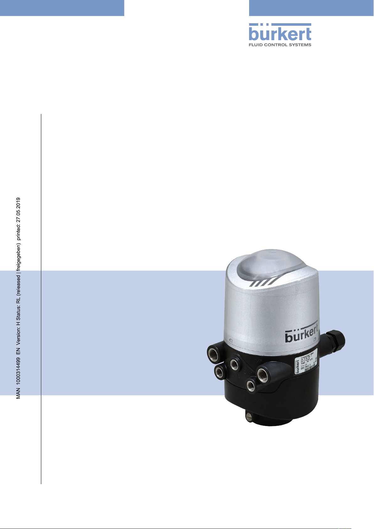
Type 8681 (büS/CANopen)
Control Head
Design: büS/CANopen
Additional Instructions for
Type 8681 büS/CANopen
Page 2

We reserve the right to make technical changes without notice.
Technische Änderungen vorbehalten.
Sous resérve de modification techniques.
© Bürkert Werke GmbH & Co. KG, 2017 - 2019
Operating Instructions 1905/07_EN_00810569 / Original DE
Page 3

Type 8681 büS/CANopen
Control Head Type 8681(büS)
Contents
1 OPERATING INSTRUCTIONS ........................................................................................................................................................6
2 BASIC SAFETY INSTRUCTIONS .................................................................................................................................................7
3 GENERAL INFORMATION ................................................................................................................................................................9
3.1 Conformity / Standards ......................................................................................................................................................9
3.2 Approvals ...................................................................................................................................................................................9
4 QUICKSTART FOR INITIAL START-UP ..................................................................................................................................10
5 CHANGES CONCERNING BÜS/CAN OPEN DESIGN ..................................................................................................11
5.1 “Autotune functions” – with reference to the Basic OI for Type 8681 ...................................................11
5.2 “Setting colour combinations” – with reference to the Basic OI for Type 8681 ...............................11
5.2.1 Device-specific LED mode “8681 Classic Mode” ..............................................................................13
5.2.2 NAMUR mode .......................................................................................................................................................13
5.2.3 Valve mode ............................................................................................................................................................14
5.2.4 Valve mode + Errors .........................................................................................................................................15
5.2.5 Valve mode + Errors + Warnings ..............................................................................................................15
5.2.6 Display mode “Fixed colour” ........................................................................................................................16
5.3 “Blinking pattern & fault signalling” – with reference to the Basic OI for Type 8681 ....................17
5.3.1 Position feedback in normal operation...................................................................................................17
5.3.2 Feedback in case of Errors / Warnings ..................................................................................................17
5.3.3 Localisation function .........................................................................................................................................19
5.4 “Signal priorities” – with reference to the Basic OI for Type 8681 ..........................................................20
5.4.1 When several states overlap for one valve ..........................................................................................20
5.4.2 When position feedback overlaps ............................................................................................................21
5.5 “Display of the status LEDs for bus error” – with reference to the Basic OI for Type 8681 ..................23
5.6 Further help ..........................................................................................................................................................................24
5.6.1 Links to different operating instructions ................................................................................................24
5.6.2 Firmware updates ..............................................................................................................................................24
6 BÜS/CAN OPEN-DESIGN ...........................................................................................................................................................25
6.1 Definition ...............................................................................................................................................................................25
english
3
Page 4

Type 8681 büS/CANopen
6.2 Network principle / Interfaces .....................................................................................................................................25
6.3 Gateway ..................................................................................................................................................................................26
6.4 Electrical connection options .......................................................................................................................................26
6.5 büS/CANopen specification .........................................................................................................................................27
6.5.1 General data ..........................................................................................................................................................27
6.5.2 Total line length and drop line lengths of the bus cables ............................................................27
6.6 Electrical data of the control head ............................................................................................................................28
6.7 Safety position if the bus fails .....................................................................................................................................29
6.8 Design aid ...............................................................................................................................................................................29
6.9 Installation – Safety instructions ................................................................................................................................30
6.10 Gateway installation ..........................................................................................................................................................30
6.11 Electrical installation - büS/CANopen ...................................................................................................................30
6.11.1 Electronic module büS/CANopen: ..........................................................................................................31
6.11.2 Terminal strip configuration: .........................................................................................................................31
6.11.3 Details on the DIP switches for colour coding: ..................................................................................32
6.12 Network topology of a büS/CANopen system ....................................................................................................32
6.13 Configuring the Node ID / baud rate .......................................................................................................................33
6.13.1 Setting the baud rate ........................................................................................................................................33
6.13.2 Setting the büS/CANopen address (Node ID) ...................................................................................34
6.13.3 Factory settings of the control head regarding the gateway configuration........................36
6.13.4 Central configuration management (Configuration client) ..........................................................37
6.14 Changing the gateway IP address ...........................................................................................................................37
6.14.1 Changing the gateway IP address using web server .....................................................................37
6.14.2 Changing the gateway IP address using “Bürkert Communicator” ........................................39
6.14.3 Changing the gateway IP address via Logix Designer ...................................................................40
6.14.4 Changing the gateway IP address using RS Linx .............................................................................43
6.15 Registration of a gateway via Logix Designer .....................................................................................................44
6.16 Installation of a gateway via Logix Designer .......................................................................................................45
6.17 Configuration of the control head network ...........................................................................................................47
6.17.1 “Hide function” via software “Logix Designer” ...................................................................................47
6.17.2 “Hide function” via “Bürkert Communicator” ......................................................................................48
6.18 Description of the (cyclical) I/O data .......................................................................................................................50
4
english
Page 5

Type 8681 büS/CANopen
6.19 Access to parameters (Read / Write) ......................................................................................................................50
6.19.1 Parameter – reading via Logix Designer ...............................................................................................51
6.19.2 Parameters – writing via Logix Designer ...............................................................................................52
6.19.3 Access to parameters via Bürkert Communicator ...........................................................................53
6.19.4 Access to further parameters (cyclic and acyclic) ...........................................................................53
7 ACCESSORIES ..................................................................................................................................................................................54
8 CABLING EXAMPLES ........................................................................................................................................56
english
5
Page 6
Type 8681 büS/CANopen
Operating instructions
1 OPERATING INSTRUCTIONS
Keep these instructions in a location which is easily accessible to every user and make these instructions available
to every new owner of the device.
WARNING!
The operating instructions contain important safety information!
Failure to observe these instructions may result in hazardous situations.
` The operating instructions must be read and understood.
Symbols:
DANGER!
Warns of an immediate danger!
` Failure to observe these instructions will result in death or serious injuries.
WARNING!
Warns of a potentially dangerous situation!
` Failure to observe these instructions may result in serious injuries or death.
CAUTION!
Warns of a possible danger!
` Failure to observe this warning may result in a moderate or minor injury.
NOTE!
Warns of material damage!
` Failure to observe these instructions may result in damage to the device or the system.
Indicates important additional information, tips and recommendations.
Refers to information in these operating instructions or in other documentation.
` Highlights instructions to avoid a danger.
→ Designates a procedure which you must carry out.
6
english
Page 7
Type 8681 büS/CANopen
Basic safety instructions
2 BASIC SAFETY INSTRUCTIONS
These safety instructions do not make allowance for any
• eventualities and events which may occur during installation, operation and maintenance of the devices.
• local safety regulations which the operator is responsible for observing, also in relation to the installation personnel.
DANGER!
Danger from high pressure!
` Before loosening lines and valves, turn off the pressure and vent the lines.
WARNING!
Danger due to electric voltage!
` Before reaching into the system (apart from the teach-in procedure in a non-explosive atmosphere), switch
off the voltage and secure to prevent it from being switched on again!
` Observe the applicable accident prevention and safety regulations for electrical equipment!
General hazardous situations.
To prevent injuries:
` Ensure that the system cannot be activated unintentionally.
` Installation and maintenance work as well as operator actions may only be carried out by authorized and suit-
ably qualified technicians using the appropriate tools.
` Do not make any unauthorized internal or external changes to the device!
` The process is restarted in a defined or controlled manner after an interruption in the power supply or pneu-
matic supply.
` The device may be installed and operated only when in perfect condition and in consideration of the operat-
ing instructions.
` The general rules of technology apply to application planning and operation of the device.
NOTE!
Electrostatic sensitive components / modules!
• The device contains electronic components which are sensitive to electrostatic discharge (ESD). Contact with
electrostatically charged persons or objects may be hazardous to these components. In the worst case scenario,
they will be destroyed immediately or will fail after start-up.
• Observe the requirements in accordance with EN 61340-5-1 to minimise or avoid the possibility of damage
caused by a sudden electrostatic discharge!
• Ensure that you do not touch the electronic components when the power supply voltage is applied!
english
7
Page 8
Type 8681 büS/CANopen
Basic safety instructions
NOTE!
Risk of damage to property!
• Do not connect any mechanically rigid connection parts, in particular those with long lever arms, as such connections could generate torques that might damage the control head.
• Do not supply the medium connections of the system with liquids or aggressive or flammable media!
• Do not subject the housing to mechanical loads (e.g. by placing objects on it or standing on it).
• Do not make any unauthorised external changes to the housings of the device. Do not paint housing parts or
screws.
• Only use compatible cleaning agents for cleaning the securely closed control head and always rinse thoroughly
with clean water.
8
english
Page 9

Type 8681 büS/CANopen
General information
3 GENERAL INFORMATION
These Additional Instructions are an supplement to the basic operating instructions for Type 8681.
They only describe the extensions and specifications for Type 8681 büS/CANopen.
“büS” (Bürkert system bus) stands for the communication bus developed by Bürkert and is based on the
CANopen protocol.
The following examples refer to the application of the EtherNet/IP protocol using a Bürkert gateway. The following
bus systems are also supported by the Bürkert Gateway:
PROFINET, Modbus/TPC, PROFIBUS DPV1, EtherCAT, CC-Link - corresponding configurations on request.
3.1 Conformity / Standards
The Control Head Type 8681 büS/CANopen complies with the EU directives according to the EU Declaration of
Conformity.
The applied standards, which are used to demonstrate compliance with the EU Directives, are listed in the EU
Prototype Examination Certificate and/or the EU Declaration of Conformity.
3.2 Approvals
The Control Head Type 8681 büS/CANopen is not authorised for those application areas which are described by
the ATEX Directive and the directives for the Underwriters Laboratories (UL) and Factory Mutual (FM).
english
9
Page 10

Type 8681 büS/CANopen
Quickstart for initial start-up
4 QUICKSTART FOR INITIAL START-UP
“büS” (Bürkert system bus) stands for the communication bus developed by Bürkert and is based on the CANopen
protocol. The following steps refer to the application of the e.g. EtherNet/IP protocol using a Bürkert gateway preconfigured for a maximum of 63 control heads.
For other gateway configurations (e.g. in conjunction with ELEMENT positioners), the specific documentation for
preconfigured Bürkert gateways must be observed.
After mounting the control heads (Type 8681 büS/CANopen) in the network, the following operations must first
be carried out on the control heads:
1.) Addressing of the control heads
According to chapter “6.13.2 Setting the büS/CANopen address (Node ID)” each control head in the network must
be assigned its own unique address (Node-ID).
When using a preconfigured gateway: For easy commissioning, each control head should be assigned its unique
node ID between 1 and 63 using the DIP switches. This allows the preconfigured communication settings between
the gateway and each control head to be used. The factory setting (address “0” = softwareconfigurable address/
node ID) should not be used furthermore.
When using a non-pre-configured gateway or when using the factory setting “0” (software-configurable
address/node ID): A device configuration via Bürkert Communicator on site is required for commissioning each
control head (see also section “6.13.3” on page 36 ).
Error-free parameter access by the Logix Designer: To ensure this, the new addresses should be selected
clearly arranged and in sequence (starting with “1” and without gaps in the numerical series!).
Any change of the device address requires a device restart.
2.) Setting the baud rate
Set the baud rates according to chapter “6.13.1 Setting the baud rate”. The combination of cable lengths and baud
rate is very important (see chapter “6.5.2 Total line length and drop line lengths of the bus cables”).
The baud rate of all devices connected to the network (including the gateway) must be the same .
Any change of the baud rate requires a device restart.
3.) “Hiding” of non-existent devices
If less than 63 devices are assigned to the gateway, the non-existent devices must be “hidden” at the gateway, both
outputs AND inputs - see chapter “6.17 Configuration of the control head network”, either using the Logix-Designer
(“6.17.1”) or Bürkert Communicator (“6.17.2”).
After the changes have been made, a device restart is required.
10
4.) Careful closing of the electrical connections
Due to moisture (including steam) in the system, all electrical connections (M12 plug-in connections) must be
firmly screwed on with 0.6 (+0.1) Nm. All open electrical connections must be well “sealed” with protective
caps (see information box in chapter “6.2 Network principle / Interfaces” and also chapters “7 Accessories” and
“8 Cabling examples”.
english
Page 11
Type 8681 büS/CANopen
Changes concerning büS/CAN open design
5 CHANGES CONCERNING BÜS/CAN OPEN
DESIGN
This chapter describes changes affecting the Control Head Type 8681 büS/CANopen design with reference to
the Basic Operating Instructions (OI) for Type 8681.
5.1 “Autotune functions” – with reference to the Basic OI for Type 8681
The optical feedback signals for the autotune mode and the autotune functions of type 8681 büS/CANopen are
different from the standard models of type 8681.
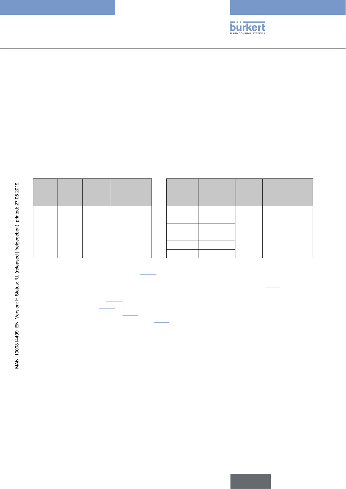
For the autotune functions, first enter the Autotune mode (T2+T3 for min. 2.5 s), then choose one of the 6 Auto tune
functions:
Teach
button
T2 + T3
Mode Activa-
tion
duration
Autotune
mode
2.5 s
optical
feedback
for “Autotune
mode active”
red +
yellow +
green
flashing
sequentially
(500 ms per
colour)
Teach
button
T1 Autotune 1
T2 Autotune 2
+
T3 Autotune 3
T1 + T2 Autotune 4
T1 + T3 Autotune 5
T2 + T3 Autotune 6
Function Activa-
tion
duration
0.5 s
optical
feedback
for “Autotune
function active”
red +
yellow +
green
flashing
sequentially
(200 ms per co-
lour) *)
*) This display for “Autotune function active” applies only to the display mode “device-specific LED mode”
(“8681 Classic 0 ... 15”) – see chapter “5.2.1”.
In the case of other display modes of the device status LED (Top LED) – compare chapter “5.2.1” – the colour
and blinking pattern display differs for the “Autotune function active”. See also:
- NAMUR mode (chapter “5.2.2”) – displayed in color orange as “function check”.
- valve mode (chapter “5.2.3”) – no display
- valve mode + errors (chapter “5.2.4”) – no display
- valve mode + errors + warnings (chapter “5.2.5”) – displayed in color orange as “function check”
5.2 “Setting colour combinations” – with reference to the Basic OI for Type 8681
Position feedback (S1, S2, S3, S4IN) of the process valve as well as error and warning messages are displayed
by means of the device status LED (Top LED) in different colours and partially blinking patterns. Different display
modes and colour combinations can be selected for Type 8681 büS/CANopen.
This display mode and the colour coding of the büS/CANopen devices can be switched using the 6 DIP switches
for colour coding on the electronic module (see “Fig. 6” on page 31).
(As of firmware version B.02.00.00 the following applies “Tab. 1”.)
english
11
Page 12
Type 8681 büS/CANopen
Changes concerning büS/CAN open design
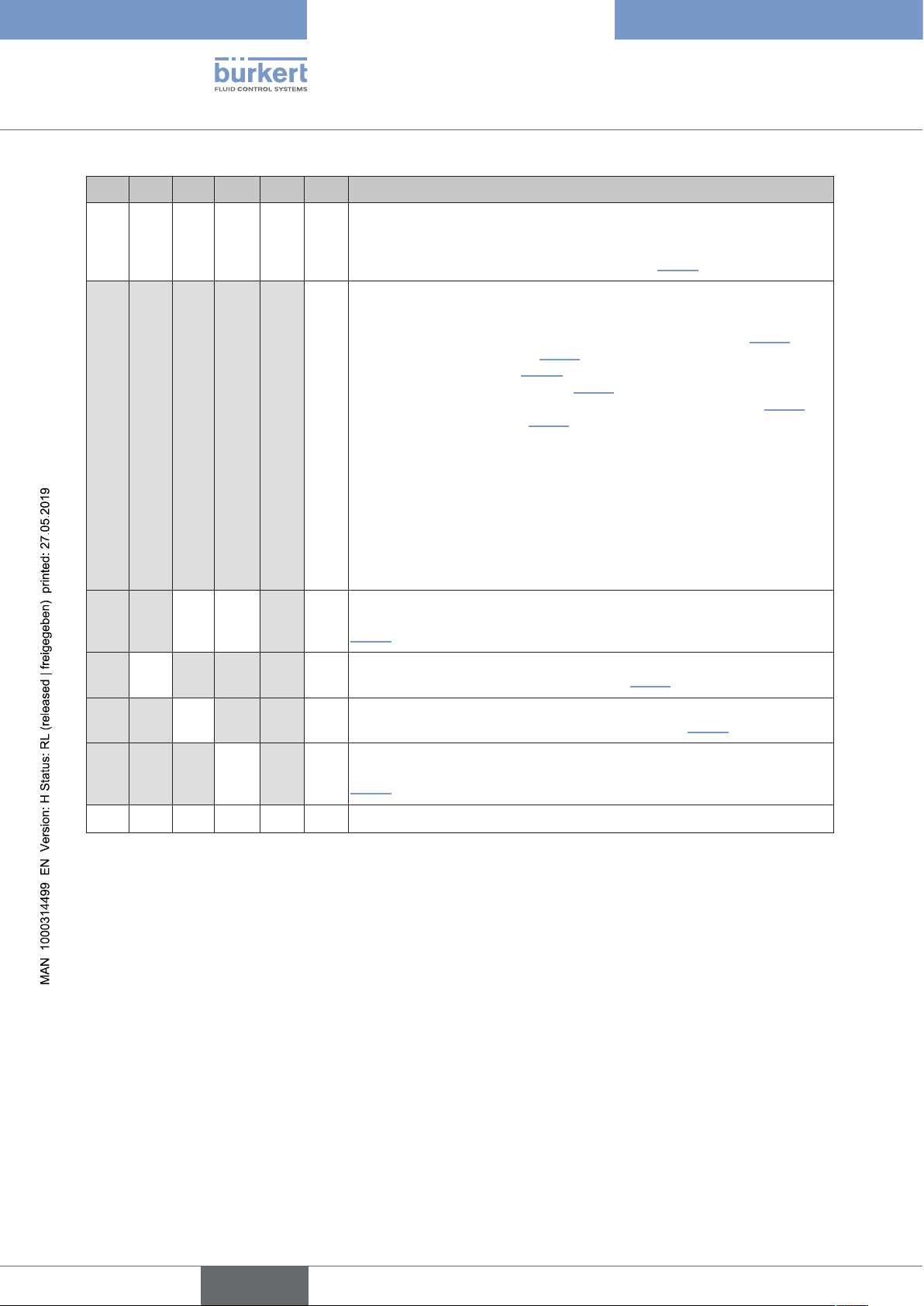
DIP1 DIP2 DIP3 DIP4 DIP5 DIP6 Description of the display modes of the device status LED (Top LED)
X X X X
0 0
8681 “Classic Mode”:
the colour combinations for the position and error feedback are set using DIP
switches 1 to 4 as described in the Basic Operating Instructions, chapter
“Setting colour combinations” – see also chapter “5.2.1”
1 1
1 1
1
1 1
1
0 0
0 1 1
0
1 1
1 1
0
Factory settings: software-configurable display mode:
display mode of the device status LED can be selected by firmware:
- Device-specific LED mode (8681 Classic 0 ... 15) – see chapter “5.2.1”
- NAMUR mode – see chapter “5.2.2”
- Valve mode – see chapter “5.2.3”
- Valve mode + errors – see chapter “5.2.4”
- Valve mode + errors + warnings (factory setting) – see chapter “5.2.5”
- Fixed colour – see chapter “5.2.6”
- (Top) LED off (there is no feedback via Top LED)
(In the Bürkert Communicator the display modes can be found under:
General settings -> Parameters -> Status LED -> Mode)
PLEASE NOTE:
Hardware-configured values (that means: set via DIP switches) overwrite the
software-configured display mode!
0
1
1
NAMUR mode:
The device status is displayed according to NAMUR NE 107 – see chapter
“5.2.2”
0
Valve mode:
Display of the position feedback – see chapter “5.2.3”
0
Valve mode + errors:
Display of the position and error feedback – see chapter “5.2.4”
12
1 1 1
X X X X X X all other combinations: (Top) LED off
Tab. 1: Colour combinations / colour coding / display modes for Type 8681büS/CANopen
0
0
1
Valve mode + errors + warnings:
Display of the position and error feedback as well as warnings – see chapter
“5.2.5”
english
Page 13
Type 8681 büS/CANopen
Changes concerning büS/CAN open design
5.2.1 Device-specific LED mode “8681 Classic Mode”
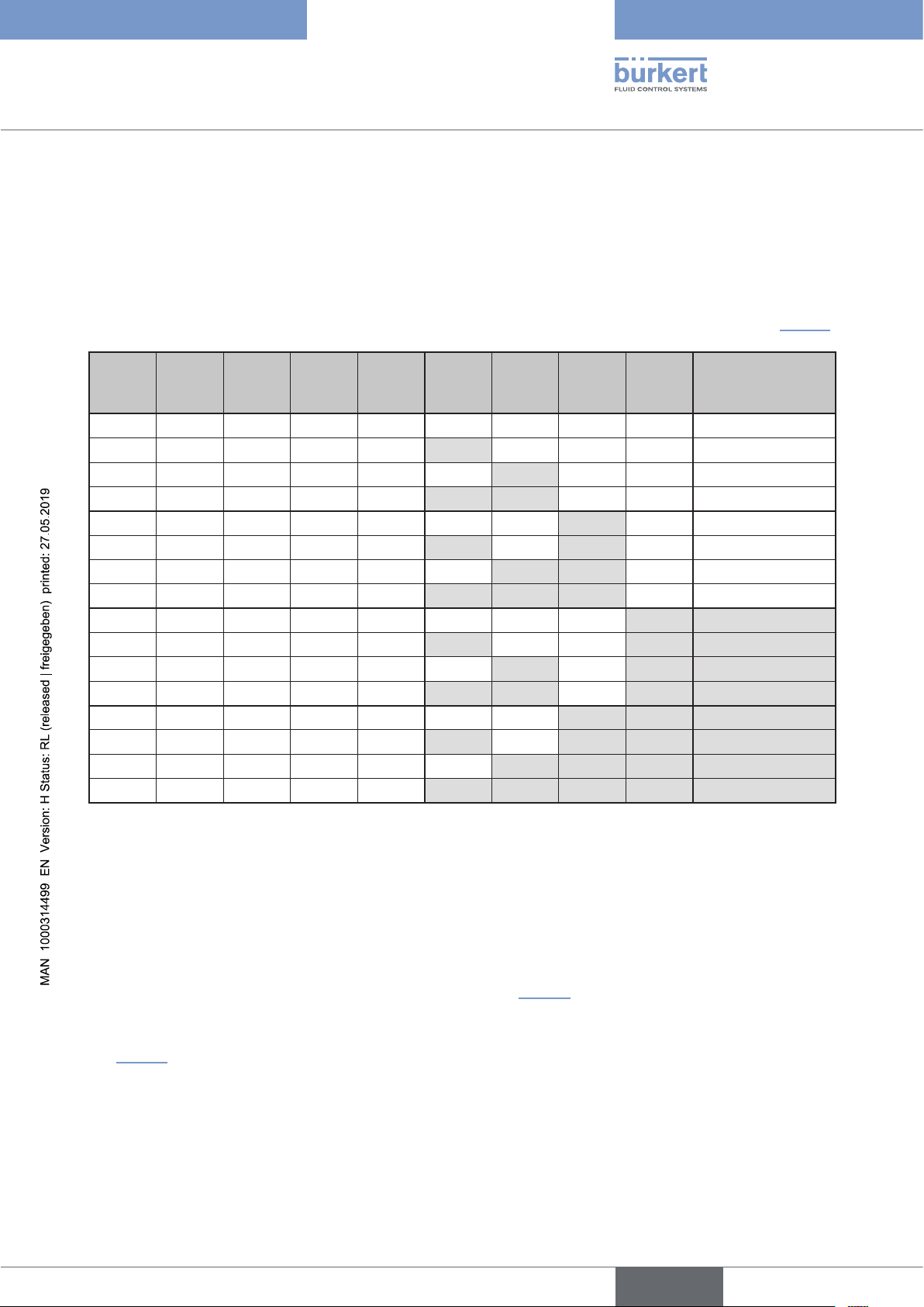
This display mode of the device status LED for the position feedback (S1, S2, S3, S4IN) of the process valve
matches the display mode of the “classic” Control Heads Type 8681 (24 V DC, AS-i, DeviceNet, 120 V AC). The
colour coding is set using DIP1 to 4 - see Basic Operating Instructions, chapter “Setting colour combinations”.
If the display mode is selected using software – e.g. via Bürkert Communicator (General Settings/Parameters/
Status LED) or via the network (e.g. via Logix Designer) – the parameter “8681 Classic X” can be selected under
“device-specific LED mode”. Which DIP switch position corresponds to the respective parameter is listed in ”Tab. 2”:
S1 S2 S3 S4 Error DIP1 DIP2 DIP3 DIP4
Designation of the
device-specific LED
mode
green yellow green red 0 0 0 0
yellow green yellow red 1 0 0 0
green red green yellow 0 1 0 0
red green red yellow 1 1 0 0
green yellow yellow red 0 0 1 0
yellow green green red 1 0 1 0
green red red yellow 0 1 1 0
red green green yellow 1 1 1 0
green yellow green green red 0 0 0 1
yellow green yellow yellow red 1 0 0 1
green red green green yellow 0 1 0 1
red green red red yellow 1 1 0 1
green yellow yellow yellow red 0 0 1 1
yellow green green green red 1 0 1 1
green red red red yellow 0 1 1 1
red green green green yellow 1 1 1 1
Tab. 2: Colour combinations / colour coding for Type 8681 büS/CANopen - device-specific LED mode “8681 Classic X”
8681 Classic 0
8681 Classic 1
8681 Classic 2
8681 Classic 3
8681 Classic 4
8681 Classic 5
8681 Classic 6
8681 Classic 7
8681 Classic 8
8681 Classic 9
8681 Classic 10
8681 Classic 11
8681 Classic 12
8681 Classic 13
8681 Classic 14
8681 Classic 15
5.2.2 NAMUR mode
The device status LED (Top LED) display the device status, they change colour according to NAMUR NE 107
(edition 2006-06-12). There is no feedback on the process valve positions (S1, S2, S3, S4IN).
This display mode can be configured by software (DIP 1 to 6: 111110) or can be fixed as of firmware revision
B.02.00.00 using DIP switches (DIP 1 to 6: 001110) – compare “Tab. 1”.
If several device statuses exist simultaneously, the device status with the highest priority is displayed. The priority is
determined by the severity of the deviation from controlled/normal operation (red LED = failure = highest priority) –
see “Tab. 3”.
english
13
Page 14
Type 8681 büS/CANopen
Changes concerning büS/CAN open design
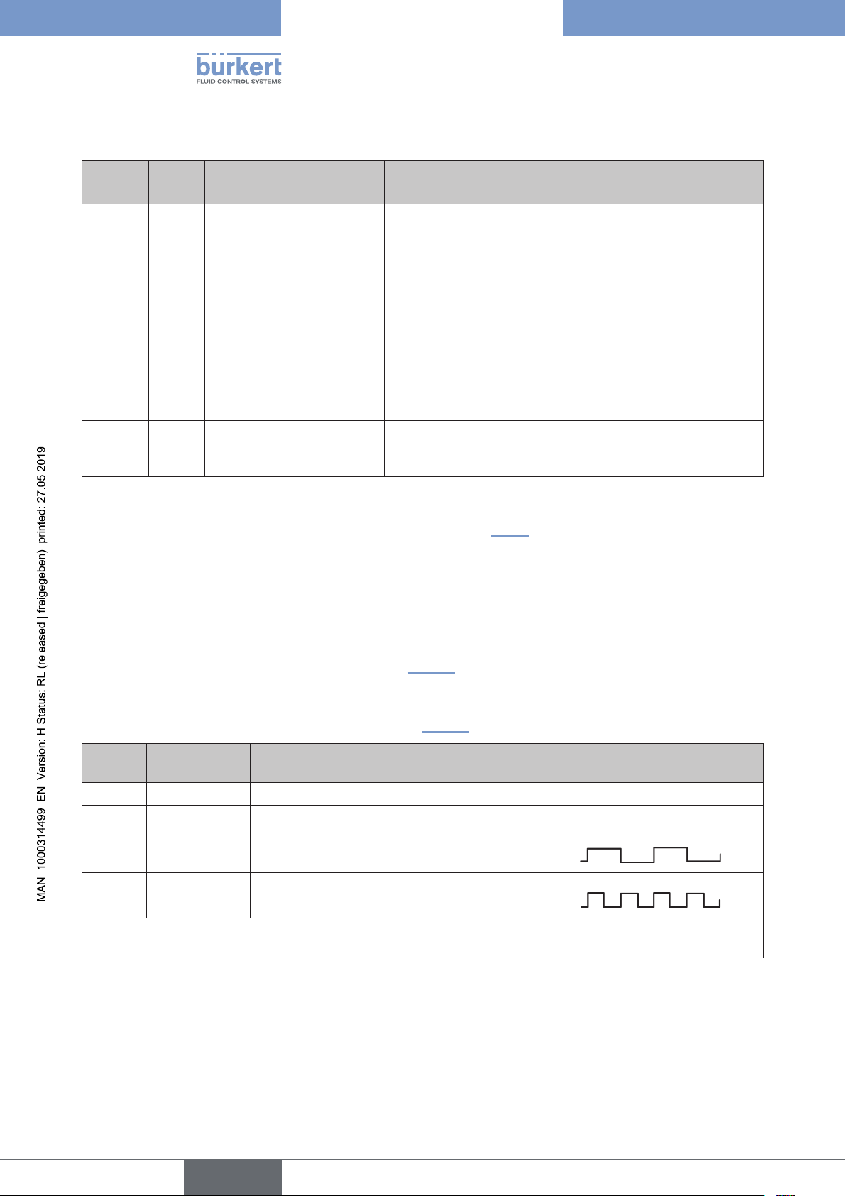
Colour*) Prio-
Description Meaning
rity
red 1 Failure, error, malfunction Controlled operation is not possible due to a malfunction in
the device or its peripheral devices.
orange 2 Function check Work is being carried out on the device; controlled operation
is therefore not currently possible
(this includes “Autotune function active”).
yellow 3 Out of specification The ambient conditions or process conditions for the device
are outside the specified area
(this includes “Teach or Autotune function required”).
blue 4 Maintenance required The device is in controlled operation, but a function is pres-
ently restricted.
→ Service the device!
green 5 Diagnostics active
(controlled operation)
Tab. 3: Description of the colours in display mode “NAMUR”
*)
If a control head is connected to the Bürkert Communicator, this control head “flashes” (single flash) in the particular co-
lour of the device status – see also the chapter on Localisation function “5.3.3”.
Device is operating faultlessly (controlled). Status changes
are indicated in different colours.
Messages are transmitted via a fieldbus if connected.
5.2.3 Valve mode
The device status LED (Top LED) display the position feedback (S1, S2, S3) of the process valve and the
feedback S4IN from the external initiator.
The position feedback is displayed as shown below in “Tab. 4”. There is no display of error and warning messages
in this mode.
This display mode can be configured by software as of firmware revision B.02.00.00 (DIP 1 to 6: 111110) or can
be fixed using DIP switches (DIP 1 to 6: 011110) – see “Tab. 1”.
Position Process valve
position, e.g.:
S1 closed
S2 open
S3 Cycle stroke
S4IN ext. Initiator,
active
If there is no position feedback (S1 to S4IN), i.e. the process valve is in intermediate positions of the defined
teach points, the Top LED is off *) ***).
Tab. 4: Description of the colours and blinking patterns in “valve mode” display mode
*) Factory settings (other selectable colours for S1 to S4IN and also for the intermediate positions:
white, green, blue, yellow, orange, red, (Top) LED off)
Colour Blinking pattern of the
position feedback
green *)
yellow *)
continuously lit
continuously lit
green *) continuously flashing slowly **)
(250 ms ON, 250 ms OFF)
green *) continuously flashing quickly **)
(125 ms ON,125 ms OFF)
14
**) Factory settings (other selectable blinking patterns: [continuously lit], [125 ms ON + 125 ms OFF],
[250 ms ON + 250 ms OFF])
***) Blinking pattern for the selected colour for the intermediate positions: continuously lit
english
Page 15
Type 8681 büS/CANopen
Changes concerning büS/CAN open design
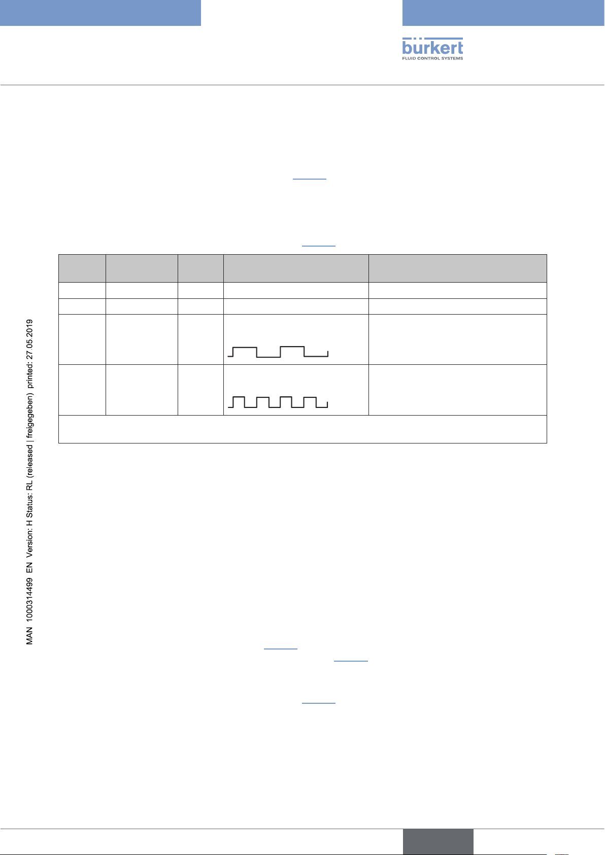
5.2.4 Valve mode + Errors
The device status LED (Top LED) display the position feedback (S1, S2, S3) of the process valve and the
feedback S4IN from the external initiator as well as error messages.
The position feedback is displayed as shown below in “Tab. 5”.
If an error (i.e. internal error, bus error, error with teach or Autotune function, positions measuring sys tem signal
error) occurs, this is also displayed alternately according to the diagram: 1 second position feedback / 1 second
error display.
This display mode can be configured by software as of firmware revision B.02.00.00 (DIP 1 to 6: 111110) or can
be fixed using DIP switches (DIP 1 to 6: 101110) – see “Tab. 1”.
Position Process valve
position, e.g.:
S1 closed
S2 open
S3 Cycle stroke
S4IN ext. Initiator,
active
If there is no position feedback (S1 to S4IN), i.e. the process valve is in intermediate positions of the defined
teach points, the Top LED is off *) ***).
Tab. 5: Description of the colours and blinking patterns in “valve mode + errors” display mode
*) Factory settings (other selectable colours for S1 to S4IN and also for the intermediate positions:
white, green, blue, yellow, orange, red, (Top) LED off)
**) Factory settings (other selectable blinking patterns: [continuously lit], [125 ms ON + 125 ms OFF],
[250 ms ON + 250 ms OFF])
***) Blinking pattern for the selected colour for the intermediate positions: continuously lit (alternating with pos-
sible error messages)
Colour Blinking pattern of the
position feedback
green *)
yellow *)
green *) continuously flashing slowly **)
green *) continuously flashing quickly **)
continuously lit is lit red alternating with colour from S1
continuously lit is lit red alternating with colour from S2
(250 ms ON, 250 ms OFF)
(125 ms ON,125 ms OFF)
Fault indication
is lit red alternating with colour from S3
is lit red alternating with colour from
S4IN
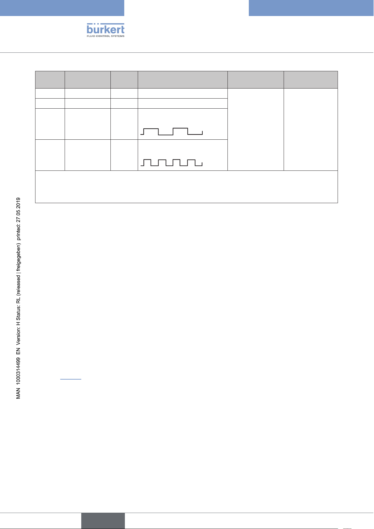
5.2.5 Valve mode + Errors + Warnings
The device status LED (Top LED) display the position feedback (S1, S2, S3) of the process valve and the
feedback S4IN from the external initiator as well as error and warning messages.
The position feedback is displayed as shown in “Tab. 6”.
If an error or a warning occurs (see colour assignment below “Tab. 6”), this is also displayed alternately:
1 second position feedback / 1 second error or warning display.
This display mode can be configured by software as of firmware revision B.02.00.00 (DIP 1 to 6: 111110) or can
be fixed using DIP switches (DIP 1 to 6: 110110) – see “Tab. 1”.
english
15
Page 16
Type 8681 büS/CANopen
Changes concerning büS/CAN open design
Position Process valve
position, e.g.:
S1 closed
S2 open
S3 Cycle stroke
S4IN ext. Initiator,
active
Colour Blinking pattern of the
position feedback
green *)
yellow *)
continuously lit is lit red
continuously lit
green *) continuously flashing slowly **)
(250 ms ON, 250 ms OFF)
green *) continuously flashing quickly **)
(125 ms ON,125 ms OFF)
Fault indication Warning display
is lit in the
(= error
colour ***)) alternating with colour
and any blinking
pattern of the
position (S1 or S2
or S3 or S4IN)
warning
colour ****)
alternating with
colour and any
blinking pattern of
the position (S1
or S2 or S3 or
S4IN)
If there is no position feedback (S1 to S4IN), i.e. the process valve is in intermediate positions of the defined
teach points, the Top LED is off *).
(Blinking pattern for the intermediate positions with selected colour (different from the factory setting “(Top)
LED off”): continuously lit, alternating with possible warning or error messages)
Tab. 6: Description of the colours and blinking patterns in “valve mode + errors + warnings” display mode
*) Factory settings (other selectable colours for S1 to S4IN and also for the intermediate positions:
white, green, blue, yellow, orange, red, (Top) LED off)
**) Factory settings (other selectable blinking patterns: [continuously lit], [125 ms ON + 125 ms OFF],
[250 ms ON + 250 ms OFF])
***) Error colour: red (internal error, bus error, error with teach or Autotune function, positions measuring
sys tem signal error)
****) Warning colours: (firmly specified):
Orange:
Function check (service mode/manual override active, Autotune function active)
Yellow: Out of specification (storage error of the operating hour/cycle counter, Teach
or Autotune function required (no position taught))
Blue: Maintenance required (Service/maintenance notification)
5.2.6 Display mode “Fixed colour”
A fixed colour can be assigned to the device - however this is possible only in software configurable display mode
(DIP 1 to 6: 111110). There is no display of process valve positions or error/warning messages in this mode –
compare “Tab. 1”.
Bürkert Communicator can be used to select the following colours:
white, green, blue, yellow, orange, red, teal, pink (factory settings: (Top) LED off).
16
english
Page 17
Type 8681 büS/CANopen
Changes concerning büS/CAN open design
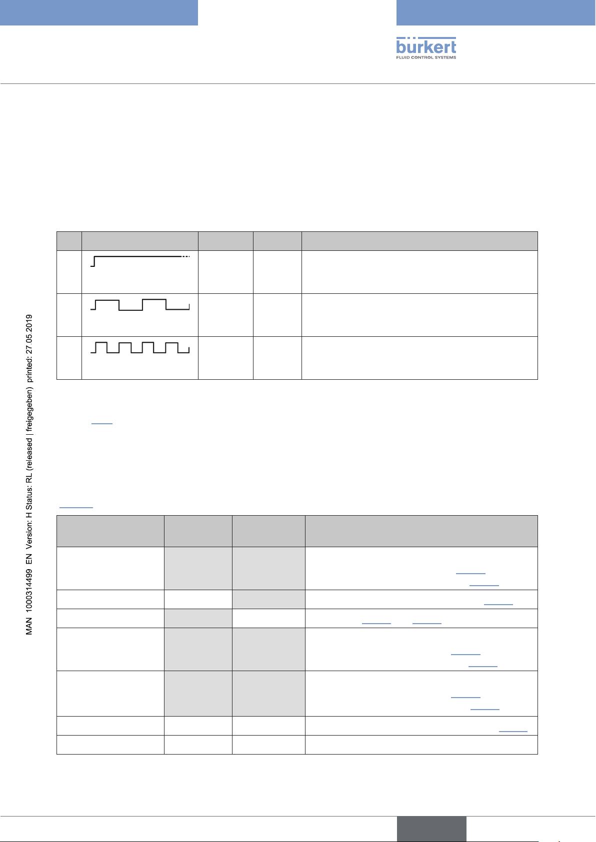
5.3 “Blinking pattern & fault signalling” – with reference to the Basic OI for Type 8681
The device status LED (Top LED) display the position feedback (positions) S1, S2, S3 of the process valve, the
feedback S4IN from the external initiator as well as error and warning messages, partly using special “blinking patterns”. How these are displayed, depends on the selected display mode of the device status LED.
5.3.1 Position feedback in normal operation
No. Blinking pattern ON OFF Note
1
2
3
Tab. 7: Position feedback in normal operation
Software can used to assign in part also other colours and blinking patterns to some display modes – compare
chapter “5.2”.
ON
250 ms 250 ms
125 ms 125 ms
continuously lit in the respective
position colour:
Signal from S1 and S2 (factory settings)
continuously flashing in the respective
position colour:
Signal from position S3 (factory settings)
continuously flashing in the respective
position colour:
Signal from the external initiator S4 (factory settings)
5.3.2 Feedback in case of Errors / Warnings
If the position feedback in controlled/normal operation and error/warning displays occur at the same time, these
are not displayed at all for some display modes or alternately for other display modes – see the following table
(“Tab. 8”) and also the blinking patterns in Tab. 9 (see on the next pages).
Display mode Position
feedback
Errors (E)+
warnings (W)
Special characteristics
“Device-specific”
(“8681 Classic”)
NAMUR no yes only device status displays - see chapter “5.2.2”
Valve mode yes no see chapter “5.2.3” and “5.4.2”
Valve mode + errors yes
Valve mode + errors +
warnings
“Fixed colour” no no permanently selected colour displaying – see “5.2.6”
“LED off” no no no displays
Tab. 8: Display behaviour of the different display modes with regard to position, error, warning
yes yes alternately:
2 seconds position feedback (see “5.4.2”) /
2 seconds error/warning display (see “5.4.1”)
alternately:
1 second position feedback (see “5.4.2”) /
1 second error display – see chapter “5.2.4”
alternately:
1 second position feedback (see “5.4.2”) /
1 second error/warning display – see “5.2.5”
yes
yes (Errors)
yes ( Errors +
Warnings)
english
17
Page 18
Type 8681 büS/CANopen
Changes concerning büS/CAN open design
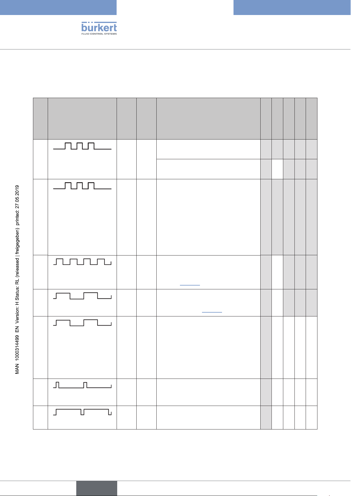
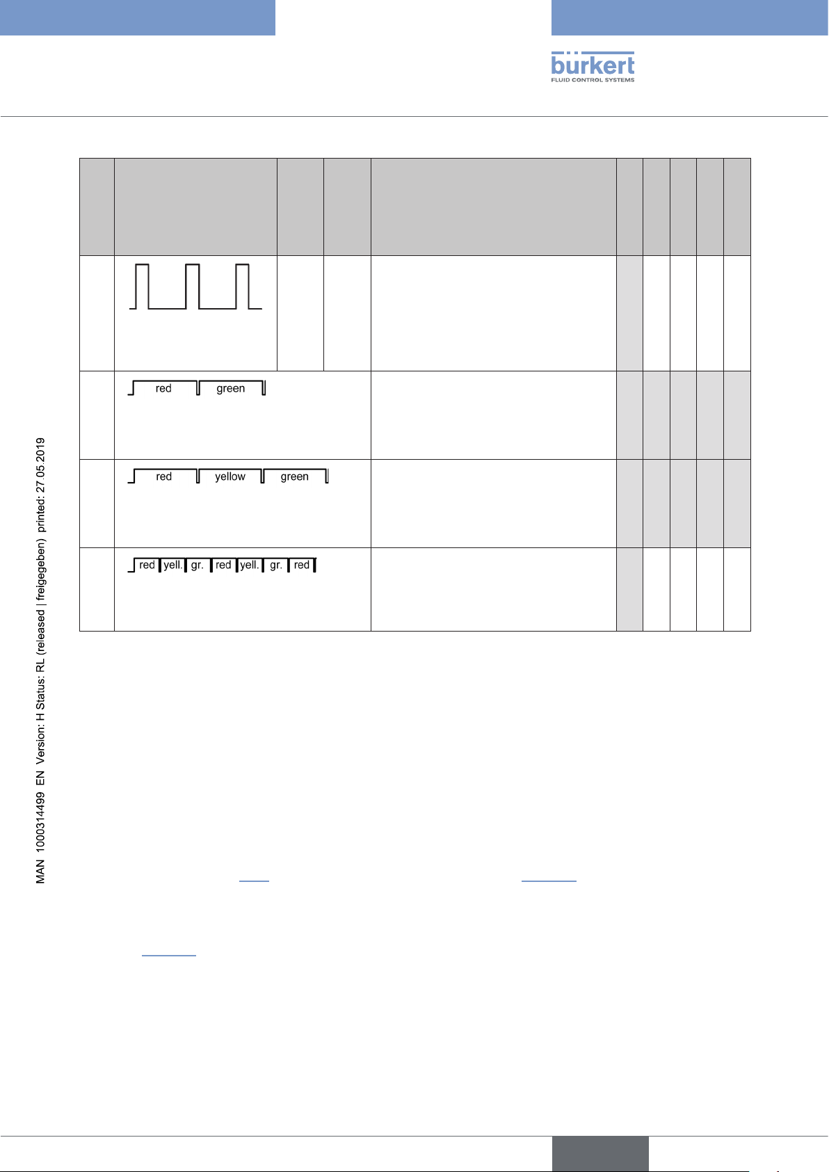
In addition to the position feedback signals, the errors and the device status in the various display modes are also
indicated by means of different blinking patterns.
Display of device status / errors / warnings
Blinking pattern / colour
(for reasons of space the
“colour of the valve position”
is designated
No.
as position
colour) ON OFF Note
Classic *)
NAMUR *)
VM *)
VM+E *)
VM+E+W *)
1
100 ms100
ms
3 x flashing:
Teach-In confirmation
x x x x x
in position colour
(after successful teaching: colour for
x x x
position 1 and 2 continuously ON)
2
in error colour
100 ms100
ms
3 x flashing:
- if target could not be located in the
measuring area during teaching or
x x x x x
- if teach position is too close
(±0.5 mm) to a previously defined
teach position or
- if magnetic manual override is used,
even though manual override function
was disabled by software
3
in position colour
125 ms125
Continuous flashing:
ms
Signal from the external initiator S4
(factory settings – comp.
x x x x
line 3 in “Tab. 7”)
4
in position colour
250 ms250
Continuous flashing:
ms
Signal from position 3 (factory settings
– comp. line 2 in “Tab. 7”)
x x x x
18
5
in error colour
250 ms250
ms
Continuous flashing:
- Teaching does not occur or
- Autotune function error or
x
- Teach Reset implemented or
- Bus error or
- Position measuring system signal
error (from firmware B.02.00.00) or
- Device Reset implemented
6
in error colour
7
in error colour
50 ms450
450 ms50
Continuous flashing:
ms
Device in service mode /
manual override active
Continuous flashing:
ms
Internal error
x
x
english
Page 19
Type 8681 büS/CANopen
Changes concerning büS/CAN open design
Blinking pattern / colour
(for reasons of space the
“colour of the valve position”
is designated
No.
as position
colour) ON OFF Note
Classic *)
NAMUR *)
VM *)
VM+E *)
VM+E+W *)
8
9
10
11
1
sec.
blue colour (position
feedback during OFF
phase)
alternately red / green
(500 ms per colour)
alternately red / yellow / green
(500 ms per colour)
3
sec.
Continuous flashing:
Service/maintenance notification (maintenance / service required)
(Position feedback occurs during OFF
phase)
Continuous flashing:
Device Reset mode active
(for Device Reset press again within
10 s)
Continuous flashing:
Autotune (selection) mode active
(for Autotune function press appropriate keys within 10 s)
Continuous flashing:
Autotune function active
x
x x x x x
x x x x x
x
alternately red / yellow / green
(200 ms per colour)
Tab. 9: Display behaviour of the different display modes with regard to, error, warning, status
*) These abbreviations mean: Classic – device specific LED mode (8681 Classic Mode X),
NAMUR – NAMUR mode (NAMUR NE 107),
“VM” – valve mode,
“VM+E” – valve mode with error messages,
“VM+E+W” – valve mode with error and warning messages
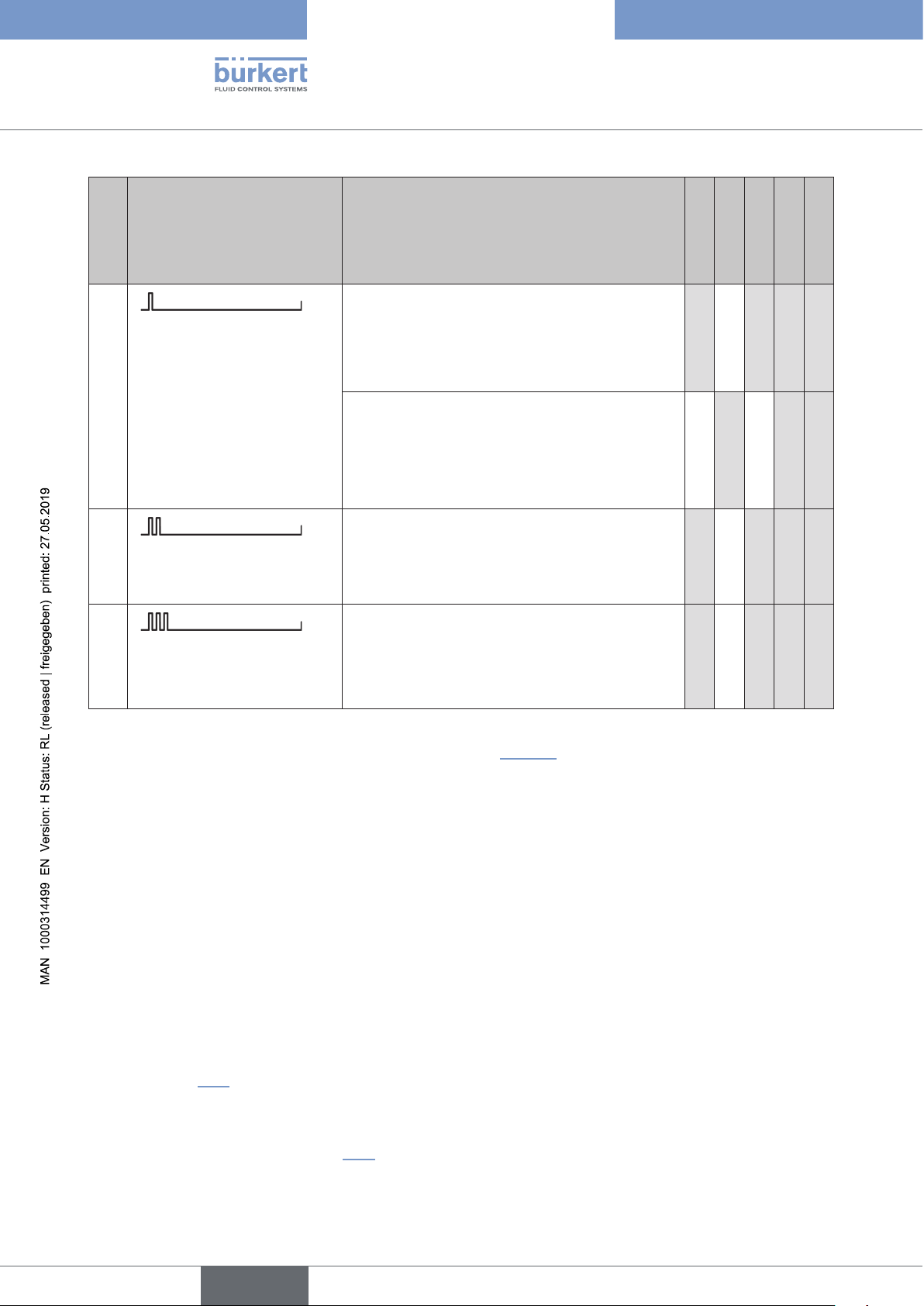
5.3.3 Localisation function
This function can be used to localise a device in the system via the control system (e.g. Bürkert Communicator).
When the localization function is activated, the device status LED (Top LED) begin to flash according to the
signal priority (see chapter “5.4”) and according to the following logic (see “Tab. 10”).
In the NAMUR mode, the device status is displayed as “single flashing”.
In the display modes VM+E and VM+E+W, any error or warning messages that may occur are displayed as
“single flashing” in the corresponding color alternating with the corresponding position feedback (S1, S2, S3 or
S4) – see “Tab. 10”.
english
19
Page 20
Type 8681 büS/CANopen
Changes concerning büS/CAN open design
No. Blinking pattern Note
1
every second:
1 x 25 ms ON
2
every second:
2 x 25 ms ON
3
every second:
3 x 25 ms ON
single flashing:
in white: no (taught)
position active
in colour from S1 or S2: S1 or S2 active
in color of the device status
or in the error colour / warning colour
alternating with the position feedback signal
(S1, S2, S3, S4), if an error or warning message
is present
double flashing:
in colour from S3: S3 active
triple flashing:
in colour from S4: S4 active
Classic *)
NAMUR *)
VM *)
VM+E *)
x x x x
x
x x
x x x x
x x x x
VM+E+W *)
20
Tab. 10: Display behaviour during active localisation function
*) These abbreviations mean: see explanations below Tab. 9 (Page 19).
5.4 “Signal priorities” – with reference to the Basic OI for Type 8681
5.4.1 When several states overlap for one valve
In this case the following priority list applies to the “device specific” display mode (“8681 Classic X”) :
1. Internal error: (error colour: 450 ms ON, 50 ms OFF)
2. Manual operating mode is active, e.g. by magnetic manual override - see chapter “18. Service mode/manual
override” (error colour: 50 ms ON, 450 ms OFF)
3. Other faults, e.g. position measuring system not taught, bus error or other
(see chapter “5.3” of these supplementary operating instructions)
4. Service / maintenance request (blue colour: 1 s ON, 3 s OFF)
The display logic described in chapter “5.2” applies to the other display modes; this is shown in detail in the
respective subchapters:
english
Page 21
Type 8681 büS/CANopen
Changes concerning büS/CAN open design
• “NAMUR” – see chapter “5.2.2”
• “Valve mode” – see chapter “5.2.3”
• “Valve mode + errors” – see chapter “5.2.5”
• “Valve mode + errors + warnings” – see chapter “5.2.5”.
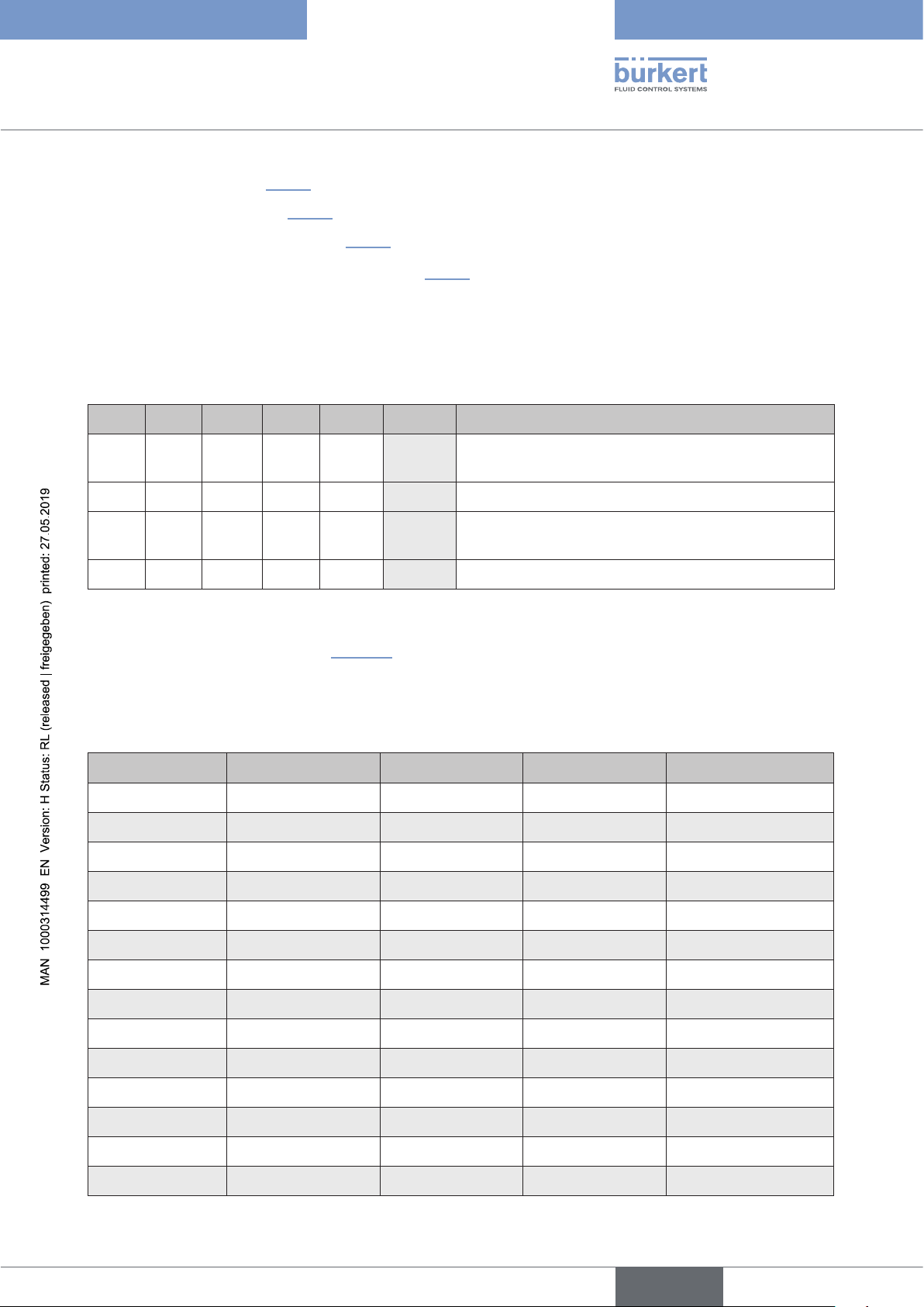
5.4.2 When position feedback overlaps
The following logic is the factory setting for all display modes:
S1 S2 S3 S4 Error Priority Note / blinking patterns
active active active
active
S4 Flashing in S4 blinking pattern (if S4 activated by DIP)
as S3/S4 has priority over S1 and S2
active active
active
active
active
S4 Flashing in S4 blinking pattern if S4 activated by DIP
S3 Flashing in S3 blinking pattern as S3/S4 has priority
over S1 and S2
active
Tab. 11: Display priorities when position feedback overlaps (factory settings)
active
S2 Position feedback of S2 has priority
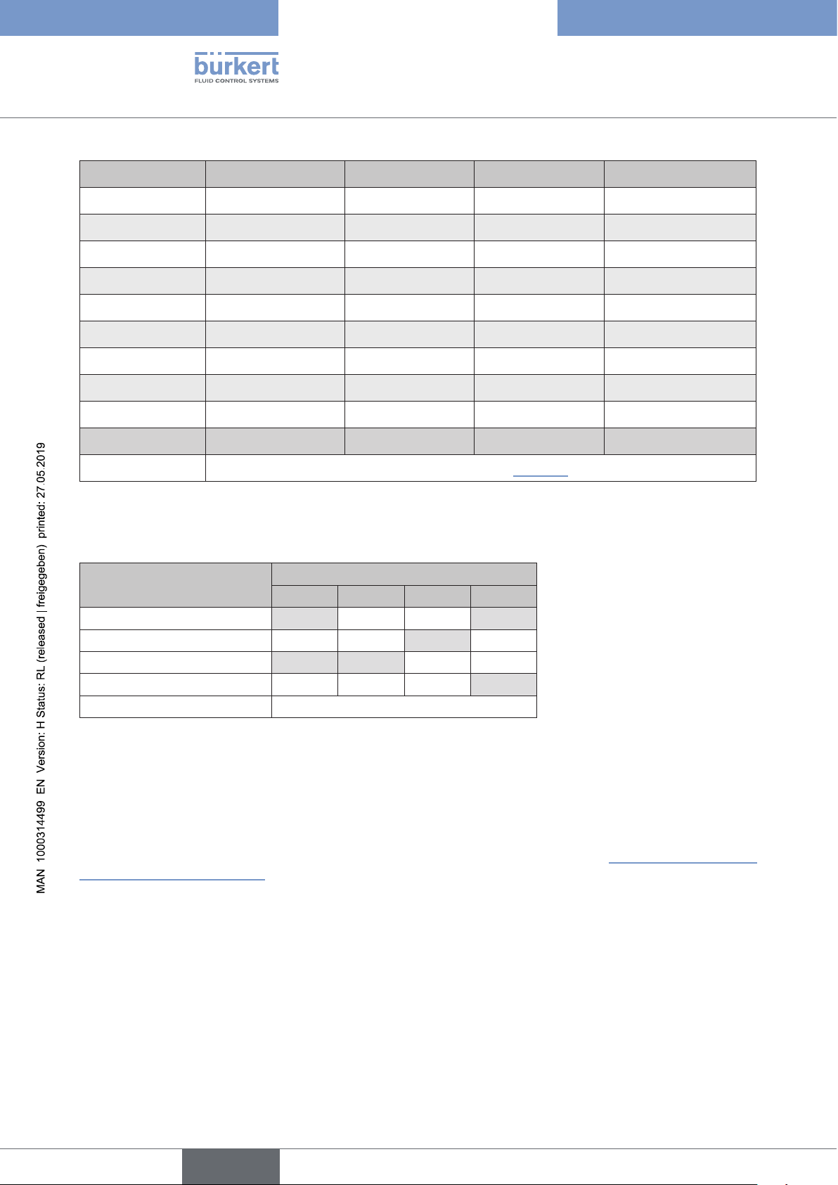
Factory settings: S4 has the highest priority, descending to S1 (i.e. S4 - S3 - S2 - S1) - this corresponds to
the “PRIO 24” in the following table (”Tab. 12”).
This display logic (described in Tab. 11 above) can be changed via software using the sensor parameter “PRIO
(priority feedback positions)”; the parameter values and the assigned display priority as follows:
Parameter “PRIO” (highest) priority 1 Priority 2 Priority 3 (lowest) priority 4
1 S1 S2 S3 S4
2 S1 S2 S4 S3
3 S1 S3 S2 S4
4 S1 S3 S4 S2
5 S1 S4 S2 S3
6 S1 S4 S3 S2
7 S2 S1 S3 S4
8 S2 S1 S4 S3
9 S2 S3 S1 S4
10 S2 S3 S4 S1
11 S2 S4 S1 S3
12 S2 S4 S3 S1
13 S3 S1 S2 S4
14 S3 S1 S4 S2
english
21
Page 22
Type 8681 büS/CANopen
Changes concerning büS/CAN open design
Parameter “PRIO” (highest) priority 1 Priority 2 Priority 3 (lowest) priority 4
15 S3 S2 S1 S4
16 S3 S2 S4 S1
17 S3 S4 S1 S2
18 S3 S4 S2 S1
19 S4 S1 S2 S3
20 S4 S1 S3 S2
21 S4 S2 S1 S3
22 S4 S2 S3 S1
23 S4 S3 S1 S2
24 *) S4 S3 S2 S1
25 particular logic, see “Tab. 13”
Tab. 12: Display priorities when position feedback overlaps - can be selected using parameter “PRIO”
*) Factory settings: “PRIO 24”
Optical feedback: Display of
the Top LED
S4 S3 S2 S1
Position feedback
S1 1 0 0 1
S2 0 0 1 0
S3 1 1 0 0
S4 0 0 0 1
no display all other combinations
Tab. 13: Special case: Display priorities when position feedback overlaps (parameter “PRIO” = “25”)
When the position feedback is from S4 (external initiator), note whether the external initiator is an “Opener” (NC
contact) or a “Closer” (NO contact). The position feedback signal “0” always means “S4 not active”, the “1” means
“S4 active”.
The factory setting of S4IN (NO - normally open) can be easily changed using the Bürkert Communicator Type
8920, but can be also overwritten with the help of the data from the parameter list - see
“6.19.4 Access to further
parameters (cyclic and acyclic)”.
22
english
Page 23
Type 8681 büS/CANopen
Changes concerning büS/CAN open design
5.5 “Display of the status LEDs for bus error” – with reference to the Basic OI for Type 8681
The following applies to the Control Heads Type 8681 büS/CANopen:
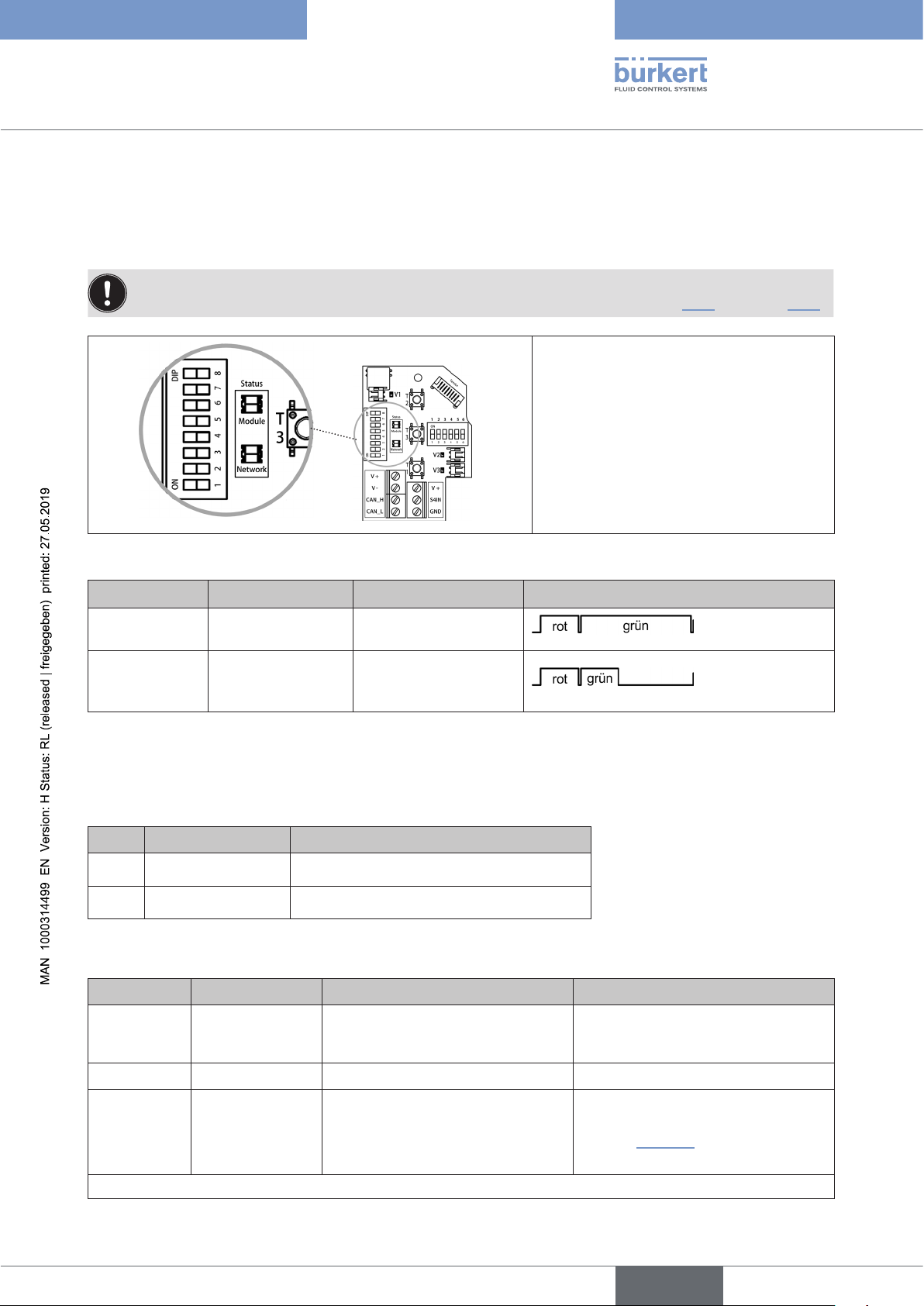
Bus errors are also indicated by the central multi-coloured status display (device status LED / Top LED)- see
chapter “Blinking pattern / fault signalling” (in the Basic Operating Instructions) and “5.3” as well as “5.4”.
Bus errors are indicated by the status LEDs
on the electronic module as well as by the
Top LED.
The device status LED (“Module”) and the
bus status LED (“Network”) are located on
the electronic module of the control head see figure beside.
Fig. 1: Status LEDs
Function tests for both status LEDs after the power has been switched on (connection of the network cable):
Status LED Colour of the LED Function test Blinking pattern
“Module” red / green 250 ms ON (red)
750 ms ON (green)
“Network” green / red 250 ms ON (red)
250 ms ON (green)
500 ms OFF
If the function test has been completed successfully, the status LEDs indicate the device status as described in
the following tables:
Status of the device status LED “Module”
LED Device status Explanation
OFF No power supply • Device is not powered
Green Device is working • normal operation
Status of bus status LED “Network”
LED Device status possible errors Remedy
OFF • No fault detected or
• device start-up phase
Green *) • No fault detected *)
Red/green *)
blinking
(500 ms/
500ms
only in bus mode
= “büs” *)
• No setpoint connection configured for controlling the
solenoid valves *)
(continued on next page)
Configure a setpoint connection for
controlling the solenoid valves (see
chapter “6.13.3”.
23
english
Page 24

Type 8681 büS/CANopen
Changes concerning büS/CAN open design
LED Device status possible errors Remedy
Red Error
- it is critical if
the LED
is still lit 2
minutes after
the last device
restart
*) Display/visualization only from firmware version B.02
• Another device with the same
Node ID is in the same network
• No bus connection (Gateway
/ PLC)
due to communication
problems or gateway restart
• Check baud rate
• Check the Node ID address (if
required, correct it so that each
address is only available once)
• Check the status of the gateway
connected to the system
• If required, replace the device
5.6 Further help
5.6.1 Links to different operating instructions
If you need further help for the configuration of Type 8681 (büS) you can also use further documents.
On the Bürkert website www.burkert.com search for the type number or the device identification number and
find the corresponding documents under “Downloads” / “User manuals” (use language filters if necessary):
Operating Instructions Type 8681 | Control Head
Operating Instructions Type ME43 | Fieldbus gateway büS to Industrial Ethernet
For configuration and parameterisation using the Bürkert Communicator, see also:
Software manual Type 8920 | Bürkert Communicator
Software manual | Central configuration management
(Search for type: ME43 / Downloads / User manual)
On the Bürkert website under “Downloads” / “Software” also can be found:
for Type 8681 büS/CANopen, the Object List for CANopen and the corresponding EDS file and
for the gateway, the Parameter List for the respective specific configuration.
To do this, enter the identification or article number of the respective device into the search field, search under
“Downloads” / “Software” the ZIP container with the “Initiation Files”, open it and download the corresponding
files.
24
5.6.2 Firmware updates
Firmware updates of the control heads, gateways (and possibly other devices) can only be carried out using the
Bürkert Communicator with the aid of a büS stick. This requires the “installer level”.
The integration of the Bürkert Communicator into the network can be seen, for example, in “Fig. 2”.
The firmware is stored in the Bürkert Communicator and is kept up to date via updates.
english
Page 25
Type 8681 büS/CANopen
büS/CAN open-Design
6 BÜS/CAN OPEN-DESIGN
6.1 Definition
The “büS” (Bürkert system bus) is a fieldbus system based on the CAN protocol (Controller Area Network).
It enables Bürkert devices to communicate with each other.
The Control Head Type 8681 büS/CANopen is a device which conforms to the specification (see chapter “6.5”).
6.2 Network principle / Interfaces
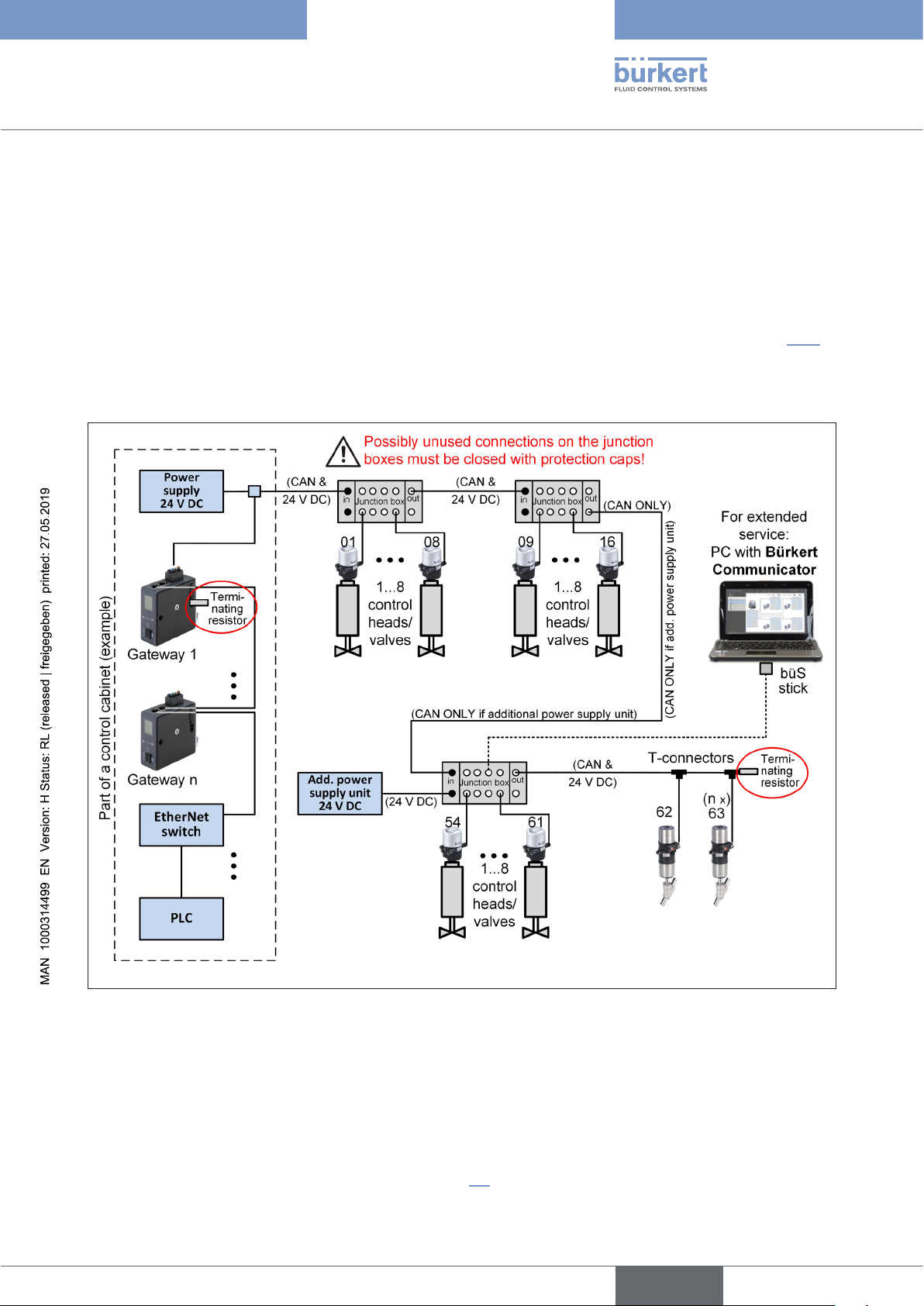
Fig. 2: Network principle
The PC with the Bürkert Communicator can be connected to each free connection in the büS network, for example
to one of the distributors.
The control head can also be connected to the Bürkert-Communicator for individual configuration. This can be done
(depending on the variant) via the M12 plug or via the connection terminal inside the device. In doing so, the control
head must also be supplied with power.
Different connection cables and a plug-in power supply unit as well as a mains adapter are included in a small
equipment case (“USB büS interface Set1” - see chapter “7”). This allows to configure also a single device.
english
25
Page 26
Type 8681 büS/CANopen
büS/CAN open-Design
• Each gateway can control up to 63 nodes (Control Heads Type 8681 büS/CANopen) if the network
topology considers the max. permitted cable length and the required power supply. Each node requires a
unique “Node ID”, otherwise an error occurs.
• The max. total line length is 200 m for 125 kbit/s, 100 m for 250 kbit/s, 40 m for 500 kbit/s.
• The max. cable length for a single drop line is 6 m, the max. total length of all drop lines in the
network is 100 m for 125 kbit/s, 55 m for 250 kbit/s, 30 m for 500 kbit/s.
• If the voltage drop is too large, an additional power supply can feed in at a CAN junction box (PWR
IN connection). In this case, connect CAN ONLY to CAN IN using a CAN cable .
This cable (which interconnects the CAN junction boxes at “CAN ONLY” and “CAN IN”) cannot be
used for T-connectors to branch “nodes” because no power is supplied to this cable (compare example
3 in chapter “8”).
• Unused or open connections must be closed with the appropriate protective caps.
• Required tightening torque for all plug-in connections (cables, T-pieces, ...) to ensure the required
leak-tightness against moisture: 0.6 Nm + 0.1 Nm.
• The CAN cable must be “terminated” at both ends: connect a terminating resistor (120 ohms) to the
end of the CAN cable / T-connector or, if the line ends with a CAN junction box, connect the terminating
resistor to the CAN OUT connection.
• For service work and also when reading out CAN data, a PC with Bürkert Communicator Type 8920
can be connected to any free connection at the CAN junction box or to the CAN ONLY connection.
A büS stick is necessary to connect the PC to the CAN network.
• T-connectors can be used to connect single “nodes” or a PC to read out the CAN data (via Bürkert
Communicator).
6.3 Gateway
EDS file for
EtherNet/IP: Gateway_EIP_8681_vxx_yymmdd_63Dev.eds
Icon: icon_me43.ico
Icon
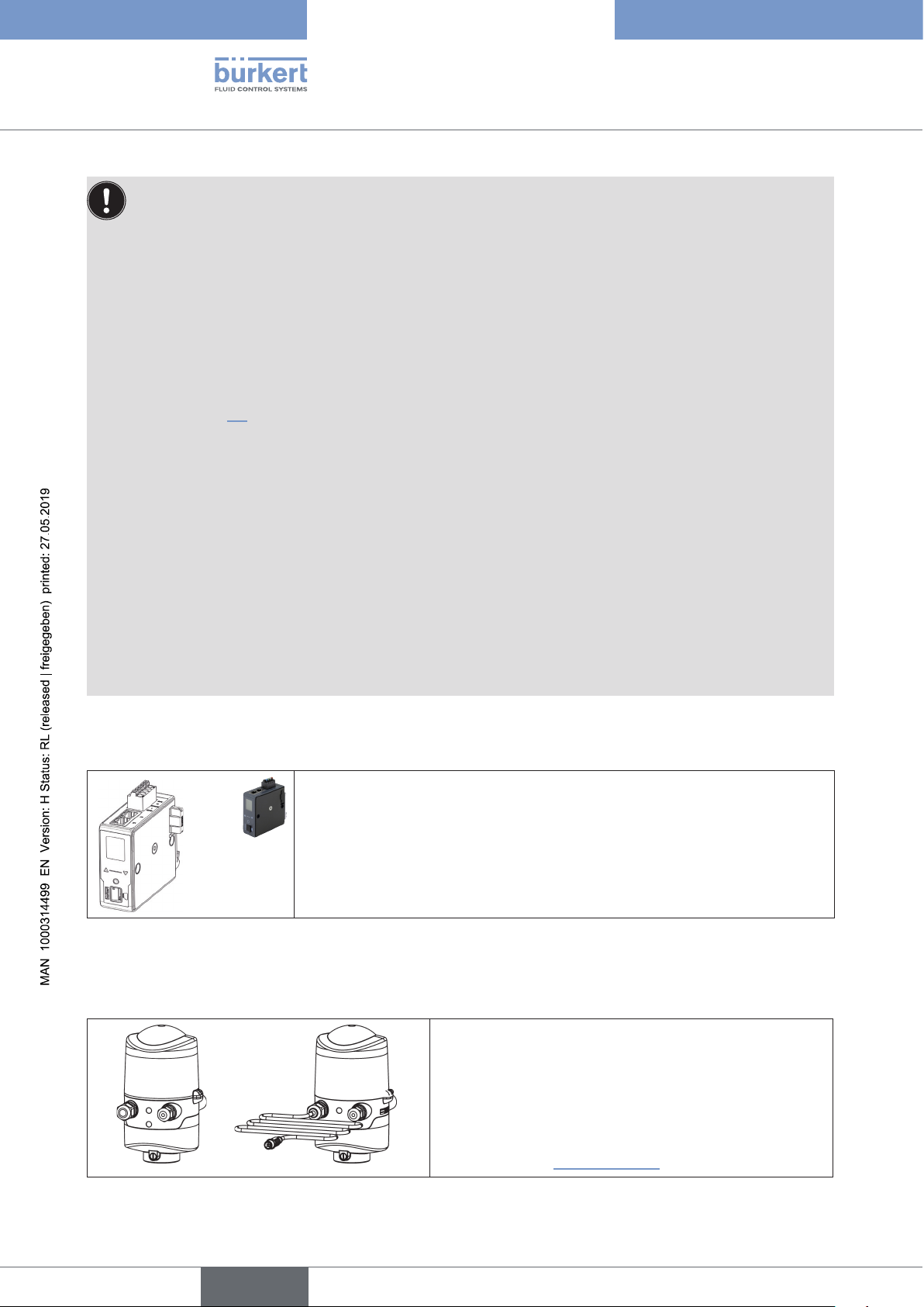
Fig. 3: Gateway ME43 with connection terminals
The Gateway Type ME43 is used as a fieldbus interface between the Control
Heads Type 8681 (büS) and the PLC (e.g. EtherNet/IP; Profinet on request).
Each gateway is designed to communicate with up to 63 control heads.
26
6.4 Electrical connection options
With cable glands
or
with cable glands and multi-pole connection
(M12 plug according to IEC 61076-2-101, 5-pole)
Connection left: voltage, signals
Connection right: external initiator
or
Fig. 4: Connection options
english
(see also chapter “7 Accessories”)
Page 27
Type 8681 büS/CANopen
büS/CAN open-Design
6.5 büS/CANopen specification
6.5.1 General data
Baud rate: configurable via DIP switches 7, 8 or via software (selectable values – see chapter
“6.13.1 Setting the baud rate”)
factory setting: software configurable baud rate (pre-selected: 500 kbit/s)
Address: 1 ... 63 (via DIP switches 1 ... 6 adjustable);
factory settings: 0 = software configurable address / Node ID
(Node ID from 1 to 127 possible; pre- selection: auto-addressing of the Node ID,
see chapter “6.13.2 Setting the büS/CANopen address (Node ID)”)
Bus mode: büS or CANopen (bus mode is software configurable only)
factory setting: büS
Process data:
Inputs: 6 byte with:
(Control head –> gateway) 4 byte position feedback in m (resolution: 1 mm)
Outputs: 1 byte for control of the 3 solenoid valves
(Gateway –> control head)
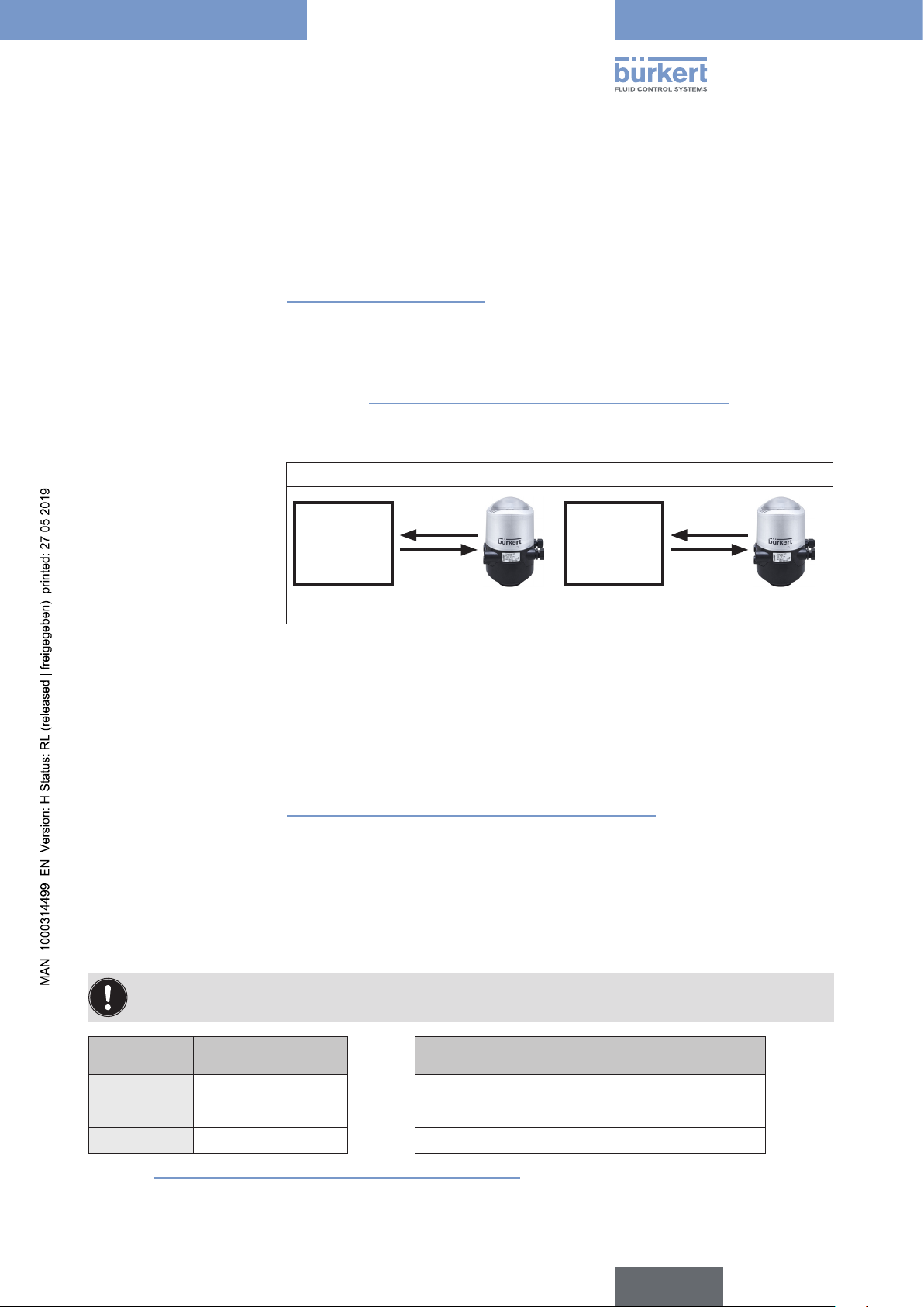
büS/CANopen or e. g. EtherNet/IP (depending on configuration)
6 byte
input
Gateway /
SPS
(Configurations for further bus systems on request)
(= feedback as cyclic position signal of the target),
1 byte NAMUR status feedback signal,
1 byte position feedback (3 discrete feedback signals from the position measuring
system (positions S1 to S3) + 1 discrete feedback signal from the external initiator (S4);
power supply via büS/CANopen cable (11 ... 25 V DC)
(The acyclic analogue position signal of the target can be read out e.g. as
parameter “8681_Current_Position_mm_DevXX” (resolution: 0.1 mm) - see chapter
“6.19 Access to parameters (Read / Write)” on page 50)
1 byte
output
Gateway /
EtherNet/IP
1 (...6) byte
input
1 byte
output
6.5.2 Total line length and drop line lengths of the bus cables
The bus line is a 4-core cable with additional shielding which must conform to the büS/CANopen specification. The
cable transmits both data/information and energy (low-voltage power supply for actuators and sensors)
The maximum total line length (sum of trunk lines and drop lines) of a network depends on the baud rate.
Some baud rates and their corresponding maximum lengths are listed in the table below.
Baud rate
125 kbit/s 200 m 6 m 100 m
250 kbit/s 100 m 6 m 55 m
500 kbit/s 40 m 6 m 30 m
Compare “Fig. 7: Network topology - büS/CANopen” on page 32.
Max. total
line length
Max. length of an
individual drop line
Max. total length of
all drop lines
english
27
Page 28

Type 8681 büS/CANopen
büS/CAN open-Design
6.6 Electrical data of the control head
Connections:
Cable gland version:
1 x M16 x 1.5 cable gland/SW19 - connection option for external initiator
1 x M16 x 1.5 cable gland / SW22 – for power supply and signals,
(only for transportation safety device sealed with dummy plugs, remove these
before use!)
for cable diameter 5 ... 10 mm, for wire cross-sections 0.14 ... 1.5 mm
2
(sealed with dummy plug, remove this before use)
Multipole connection version:
1 x M16 x 1.5 cable gland/SW22 with M12 plug according to IEC 61076-2101, 5-pole on a cable 80 cm in length for büS/CANopen and power supply
1 x M16 x 1.5 cable gland/SW19 - connection option for external initiator
(sealed with dummy plug, remove this before use)
Power supply: 11 … 25 V DC
Power consumption
(standby current): <60 mA at 24 V DC
Max. power consumption: <180 mA at 24 V DC (see chapter “6.8”)
Power consumption
(normal operation): <165 mA at 24 V DC (3 solenoid valves active, 1 position feedback with
LED display, no external initiator)
Input / proximity switches (external initiator: S4 in):
Power supply: via the büS/CANopen power supply - 10%
Current carrying capacity sensor
supply: max. 30 mA
Short-circuit protection
Design: DC 2- and 3-wire,
Normally open contact, PNP output
Input current 1 signal: I
Input voltage 1 signal: U
Input current 0 signal: I
Input voltage 0 signal: U
> 6.5 mA, limited internally to 10 mA
Sensor
> 10 V
Sensor
< 4 mA
Sensor
< 5 V
Sensor
Inputs (from master perspective) / binary or analogue feedback signals:
The recovery of the 3 valve positions reported back in binary format or the analogue position signal is described in
the Basic Operating Instructions in the chapter “Position measuring system”. The analogue target position signal
(resolution: 0.1 mm) is available in the büS/CANopen network as an acyclic value / parameter.
28
Outputs (from master perspective) / solenoid valves:
Typ. switching capacity: 0.9 W (per solenoid valve, for 200 ms after the power has been switched on)
typ. continuous output: 0.6 W (per solenoid valve, from 200 ms after the power has been switched on)
Output reduction: via the büS/CANopen interface - electronics integrated
Typ. pull-in current: 38 mA or 0.9 W / 200 ms (per solenoid valve)
Typ. holding current: 25 mA or 0.6 W at 24 V DC (per solenoid valve)
Operating mode: Continuous operation (100% duty cycle)
Valve types: 6524
Central display of the switching statuses:
Current consumption from büS/CANopen
at 24 V DC:
approx. 30 mA with a power supply of 24 V DC per illuminated display; colour
switching see chapter 17. “LED colour assignments” (in the Basic Operating
Instructions) and chapters “5.3”
and “5.4”.
english
Page 29
Type 8681 büS/CANopen
büS/CAN open-Design
6.7 Safety position if the bus fails
If the bus fails, the solenoid valve is switched to a programmable safety position (default: solenoid valve de-energised).
For configuration data / parameter see chapter “6.19 Access to parameters (Read / Write)”.
6.8 Design aid
Power consumption of the electronics:
P
El
Power consumption of a valve during activation (200 ms):
P
Valve-ON
Power consumption of a valve after reduction:
P
Valve
= 1.3 W or I
= 0.9 W or I
= 0.6 W or I
El
Valve-ON
Valve
= 54 mA at 24 V
= 38 mA at 24 V
= 25 mA at 24 V
Power consumption of an optical position feedback:
P
LED
= 0.7 W or I
LED
= 30 mA at 24 V
Calculation examples:
Example 1:
3 valves are activated, one position is reported (state for 200 ms): the control head switches automatically one valve
after another to keep the current consumption low - i.e.: max. current consumption I
= current consumption of
Total l, max.
2 valves (already activated) + 1 valve (just switching)
P
= P
Total
El
+ 2 x P
Valve
+ 1 x P
Valve-ON
+ 1 x P
LED
4.1 W = 1.3 W + 2 x 0.6 W + 1 x 0.9 W + 1 x 0.7 W
or
I
@ 24 V = I
Total
El
+ 2 x I
Valve
+ 1 x I
Valve-ON
+ 1 x I
LED
172 mA = 54 mA + 2 x 25 mA + 1 x 38 mA + 1 x 30 mA
Example 2:
3 valves have been activated, one position is reported (persistent state):
P
= P
Total
El
+ 3 x P
Valve
+ 1 x P
LED
3.8 W = 1.3 W + 3 x 0.6 W + 1 x 0.7 W
or
I
@ 24 V = I
Total
El
+ 3 x I
Valve
+ 1 x I
LED
159 mA = 54 mA + 3 x 25 mA + 1 x 30 mA
When using an external initiator, its power requirement should be added.
29
english
Page 30
Type 8681 büS/CANopen
büS/CAN open-Design
6.9 Installation – Safety instructions
WARNING!
Risk of injury due to electric shock!
` Before reaching into the system (apart from the teach-in procedure in a non-explosive atmosphere), switch off
the voltage and secure to prevent it from being switched on again!
` Observe the applicable accident prevention and safety regulations for electrical equipment!
` When setting the position measuring system (Teach-In), do not touch any live components!
Risk of injury due to improper installation!
` Installation may be carried out by authorised technicians only and with the appropriate tools!
Risk of injury due to unintentional activation of the system and uncontrolled restart!
` Secure system against unintentional activation!
` Following installation, ensure a controlled restart.
The mechanical and pneumatic installation of the control heads is described in detail in the Basic OI.
6.10 Gateway installation
→ Mount the gateway(s) on a top hat rail in the control cabinet
→ Connect the gateway(s) as described in the next chapter and as shown in chapter “6.2 Network principle /
Interfaces”
→ Connect gateway(s) to the master controller (PLC) via for example EtherNet/IP
6.11 Electrical installation - büS/CANopen
For the multipole connection variants:
No internal cabling work is required for any of the “büS” variants (with multipole connection) which makes installation and start-up on site considerably easier and quicker, reducing the risk of leaks.
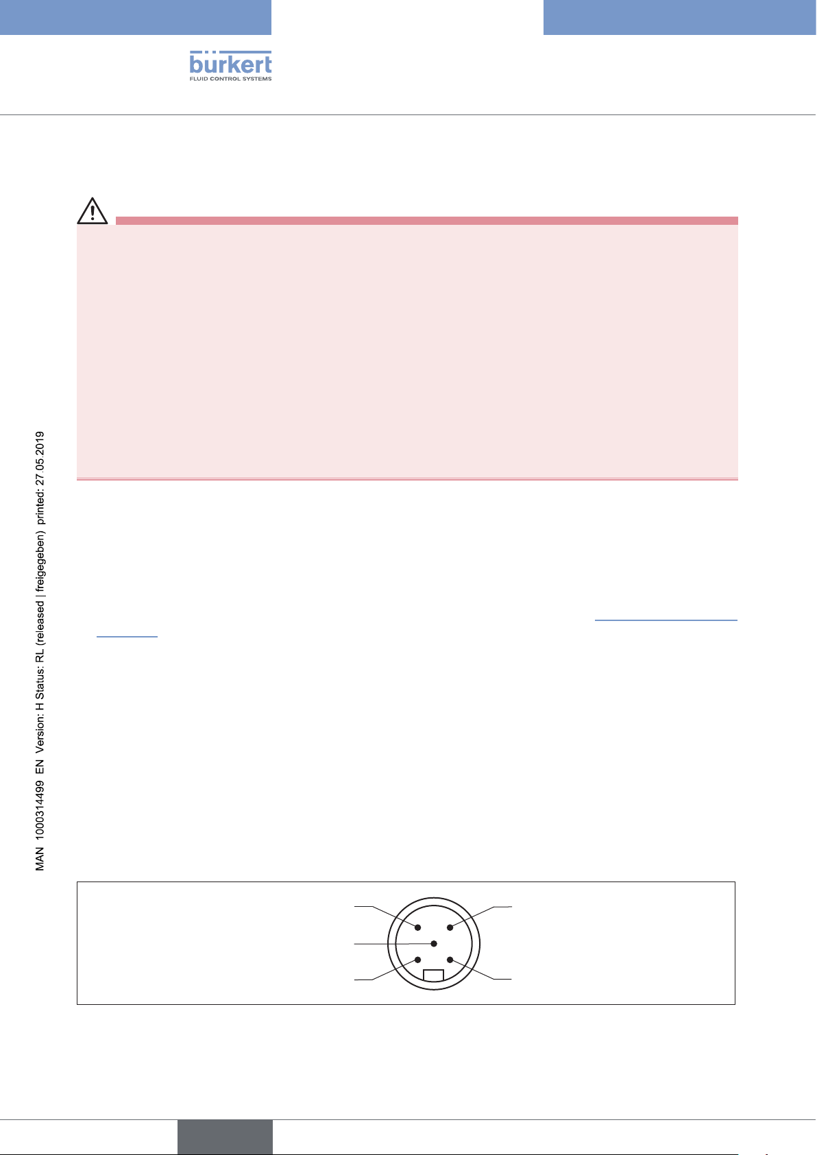
The control head features a multipole circular plug (M12 x 1, 5-pole, male) to an 80 cm long cable. The assignment
conforms to the büS/CANopen specification.
However, you will require the correspondingly assembled cable sets with the pin assignments described below:
30
View of plug from the
front onto the pins:
Fig. 5: Bus connection büS/CANopen with power supply
english
Pin 4: CAN_H
white
Pin 5: CAN_L
blue
Pin 1: Drain
(shielding)
Pin 3: V–
black
Pin 2: V+
red
Page 31
Type 8681 büS/CANopen
büS/CAN open-Design
For the versions with cable glands:
→ Open the housing (compare chapter 8 “Opening and closing the housing” in the Basic Operating Instructions
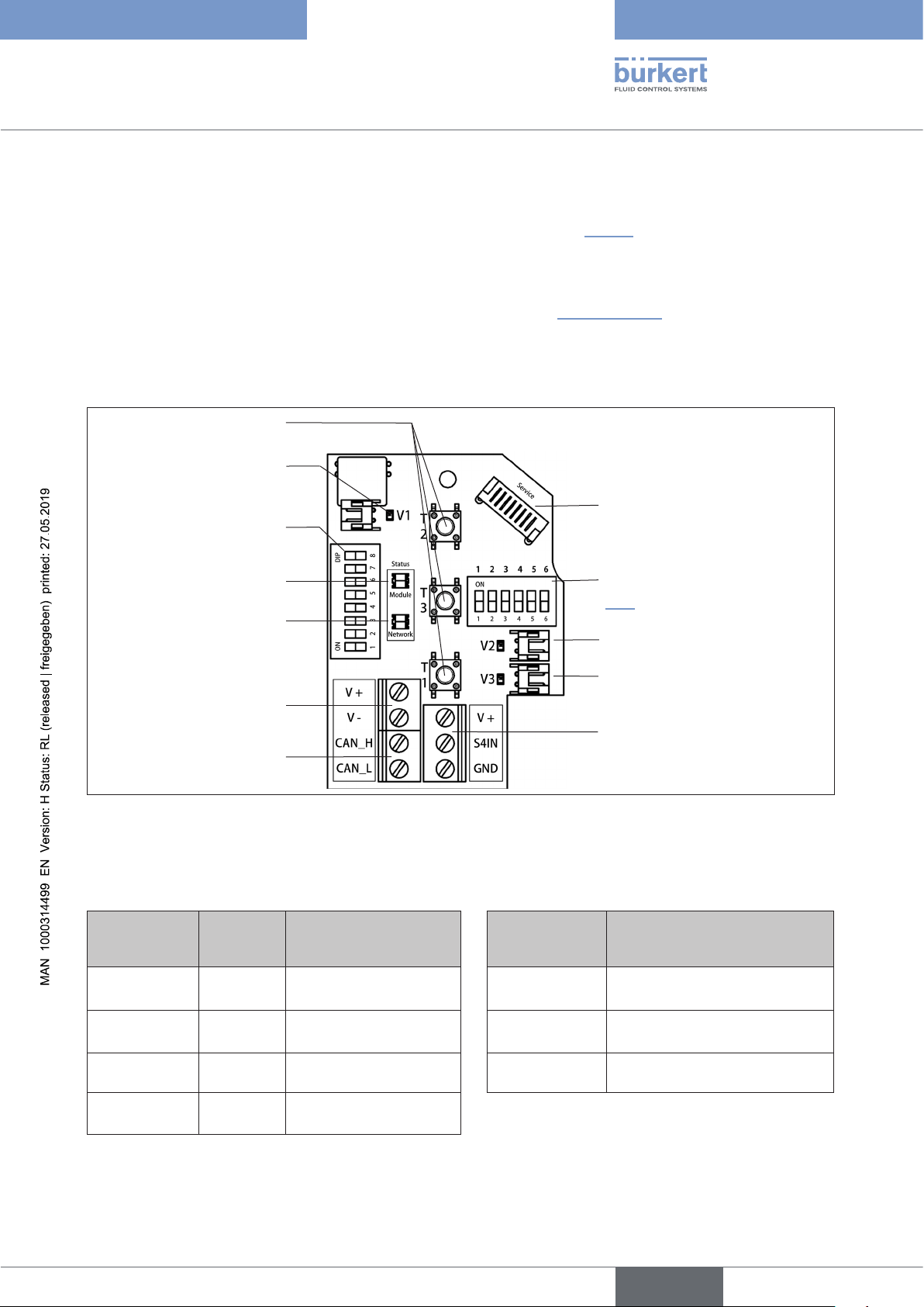
for Type 8681) so that this electronic module is visible as shown below (“Fig. 6”) .
→ Connect the different wires of the CAN cable to the screw terminals for the bus signal as specified in the table
“Terminal strip configuration”. The configuration conforms to the büS/CANopen specification.
→ The order numbers of the required CAN cables are listed in chapter “7 Accessories”
6.11.1 Electronic module büS/CANopen:
Teach-In buttons T1-3
Solenoid valve connection
with status LED for Valve 1
DIP switches for setting
address and baud rate
Status LED for device
Status LED for network
Power supply
büS/CANopen
Bus signals
Fig. 6: Electronic module büS/CANopen
6.11.2 Terminal strip configuration:
Designation
Terminal
strip
V+ red
V- black
Wire
colour
Assignment
Power supply
büS/CANopen
Power supply
büS/CANopen
Service interface
DIP switches for colour coding
the Top LED (for more details see
“5.2”)
Solenoid valve connections with status LED
for Valves 2, 3
Connection of the external
initiator
Designation
Terminal strip
V +
Assignment
Power supply for external
initiator
S4 IN External initiator input
CAN_H white Bus signal CAN high GND GND external initiator
CAN_L blue Bus signal CAN low
For connecting the external initiator - compare Basic Operating Instructions, chapter “Connection of an external
initiator”.
english
31
Page 32
Type 8681 büS/CANopen
büS/CAN open-Design
6.11.3 Details on the DIP switches for colour coding:
The (classic) colour combinations can be set via DIP 1 to 4 as described in the Basic Operating Instruction, chapter
“Setting the colour combinations”. But on this occasion DIP 5 and DIP 6 have to be set to “OFF” to display the
correct colours.
As of firmware B.02.00.00 there are software configurable display modes for the device status LED (Top LED) – details
are specified in chapter “5.2”.
Other parameters or configurations require the use of the CANopen object list or parameter list - see “6.19.4 Access
to further parameters (cyclic and acyclic)”.
6.12 Network topology of a büS/CANopen system
When installing a büS/CANopen system, ensure that the terminating circuit of the data lines is correct. The circuit
prevents the occurrence of interference caused by signal reflection in the data lines.
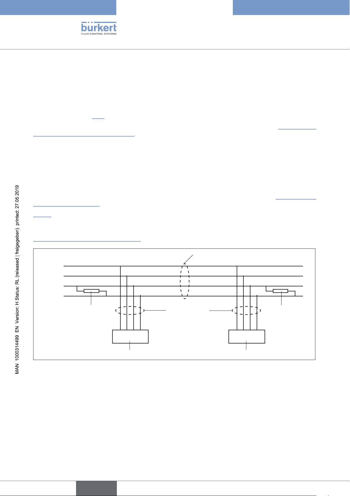
The trunk line must be terminated at both ends with 120 Ω resistors and 1/4 W power loss - see “Fig. 7: Network
topology - büS/CANopen”.
“Fig. 7” illustrates a line with one trunk line and several drop lines. Trunk lines and drop lines consist of identical
material.
A unique Node ID (büS/CANopen address) can be allocated to each control head via DIP switches - see chapter
“6.13 Configuring the Node ID / baud rate”).
Trunk line
V +
V –
CAN_H
CAN_L
Terminating
resistor
120 Ω
¼ W
Node 01 Node n
Control head 1 (node 1) Control head n (node n)
Fig. 7: Network topology - büS/CANopen
Drop lines
büS/CANopen
cable,
max. 6 m long
büS/CANopen cable
Terminating
resistor
120 Ω
¼ W
32
english
Page 33
Type 8681 büS/CANopen
büS/CAN open-Design
6.13 Configuring the Node ID / baud rate
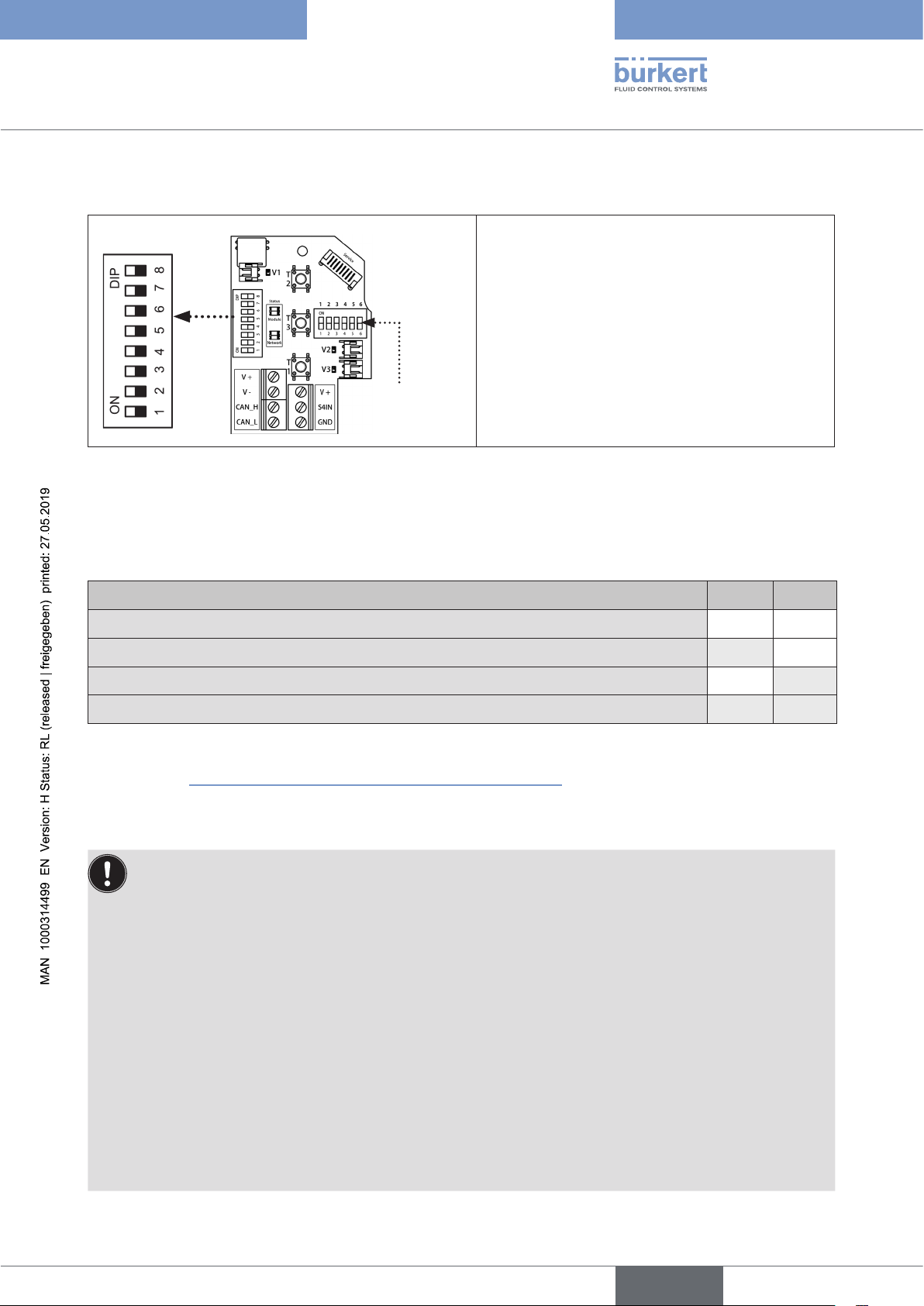
DIP switches for address+ baud rate
8 DIP switches are available for configuration:
• DIP switches 1 to 6 for the Node ID (büS/
CANopen address)
• DIP switches 7 to 8 for the baud rate
Please note:
Values fixed by DIP switches invalidate software-
DIP switches for
colour configuration
Fig. 8: Position of the DIP switches
configured values!
6.13.1 Setting the baud rate
Adjustment of the control head to the baud rate of the network:
Baud rate DIP 7 DIP 8
125 kbit/s off off
250 kbit/s on off
500 kbit/s off on
Factory settings: software configurable baud rate*) with pre-setting: 500 kbit/s
on on
*) Via software (Bürkert Communicator) configurable baud rates: 50, 125, 250, 500, 1000 kbit/s;
via software (CANopen/SPS) additionally configurable baud rates: 10, 20, 100 kbit/s
(see chapter
“6.19.4 Access to further parameters (cyclic and acyclic)”).
Please note: The baud rate of all network participants (control heads, gateway, possibly other products) must
correspond to each other!
To apply any changes to settings, restart the device!
If the settings are changed by actuating the DIP switches, these changes will not take effect until the device
is restarted! For a restart:
• trigger a restart command via Bürkert Communicator or
• briefly disconnect the control head from the power supply and reconnect or
• switch the power supply off/on or
• transmit an appropriate reset message.
Special characteristics for configuration of the “software configurable baud rate”:
• Hardware configured values (via DIP switch) have priority over software configured values!
• If the DIP switches were set to “software configurable baud rate”, the current baud rate is still valid - until
a new baud rate is selected via software. Then restart the device!
Example: Resetting the factory setting without using the software:
Set DIP7+8 to 500 kbit/s. Restart device. Then set DIP7+8 to “software configurable”. Restart device.
33
english
Page 34
Type 8681 büS/CANopen
büS/CAN open-Design
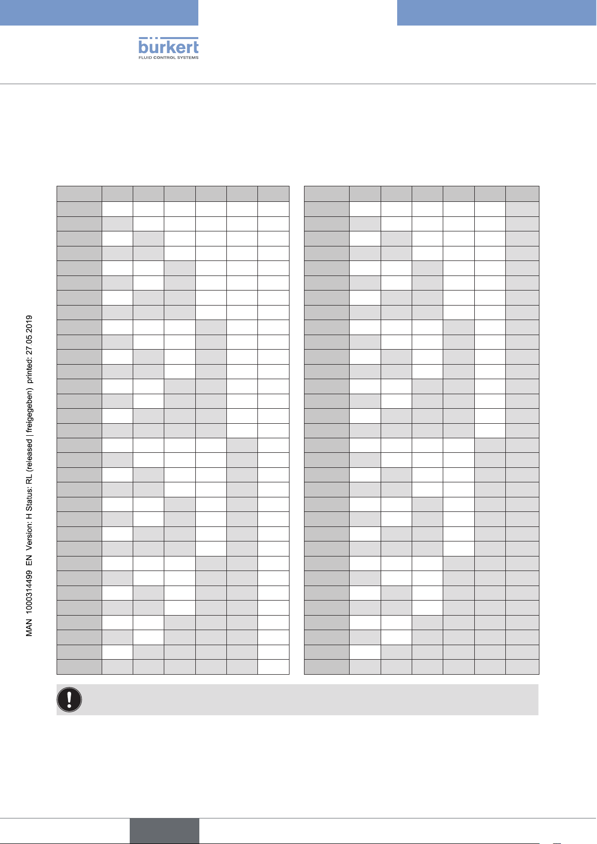
6.13.2 Setting the büS/CANopen address (Node ID)
Node ID = [DIP 1 ⋅ 20 + DIP 2 ⋅ 21 + DIP 3 ⋅ 22 + DIP 4 ⋅ 2
3
+ DIP 5 ⋅ 24 + DIP 6 ⋅ 25]
with DIP x = off = 0 and DIP x = on =1
Table of settings of the büS/CANopen address:
Node ID DIP1 DIP2 DIP3 DIP4 DIP5 DIP6 Node ID DIP1 DIP2 DIP3 DIP4 DIP5 DIP6
0 *) off off off off off off
32 off off off off off on
1 on off off off off off 33 on off off off off on
2 off on off off off off 34 off on off off off on
3 on on off off off off 35 on on off off off on
4 off off on off off off 36 off off on off off on
5 on off on off off off 37 on off on off off on
6 off on on off off off 38 off on on off off on
7 on on on off off off 39 on on on off off on
8 off off off on off off 40 off off off on off on
9 on off off on off off 41 on off off on off on
10 off on off on off off 42 off on off on off on
11 on on off on off off 43 on on off on off on
12 off off on on off off 44 off off on on off on
13 on off on on off off 45 on off on on off on
14 off on on on off off 46 off on on on off on
15 on on on on off off 47 on on on on off on
16 off off off off on off 48 off off off off on on
17 on off off off on off 49 on off off off on on
18 off on off off on off 50 off on off off on on
19 on on off off on off 51 on on off off on on
20 off off on off on off 52 off off on off on on
21 on off on off on off 53 on off on off on on
22 off on on off on off 54 off on on off on on
23 on on on off on off 55 on on on off on on
24 off off off on on off 56 off off off on on on
25 on off off on on off 57 on off off on on on
26 off on off on on off 58 off on off on on on
27 on on off on on off 59 on on off on on on
28 off off on on on off 60 off off on on on on
29 on off on on on off 61 on off on on on on
30 off on on on on off 62 off on on on on on
31 on on on on on off 63 on on on on on on
34
To apply any changes to settings, restart the device!
(See NOTE box 1 on next page for restarting)
*) This is the factory setting. (For explanations see NOTE box 2 on next page)
For easy start-up when using a preconfigured gateway, a node ID between 1 and 63 should be set on the
device using the DIP switches. Otherwise, a device configuration on site via Bürkert Communicator is required
for start-up.
english
Page 35
Type 8681 büS/CANopen
büS/CAN open-Design
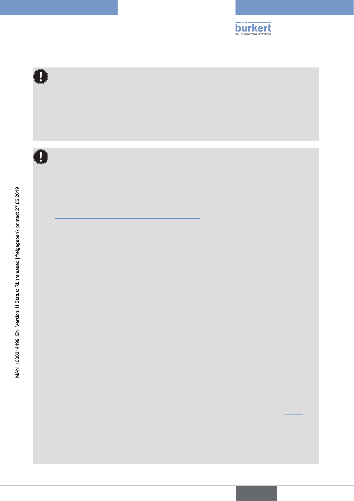
NOTE
1: How to restart the device
If the settings are changed by actuating the DIP switches, these changes will not take effect until the
device is restarted! For a restart:
• trigger a restart command via Bürkert Communicator or
• briefly disconnect the control head from the power supply and reconnect or
• switch the power supply off/on or
• transmit an appropriate reset message.
NOTE
2: Special characteristics for the DIP switch setting DIP1 to DIP6 “000000”
• This setting is the factory setting, i.e. software configurable address/Node ID.
The further behavior in the network depends on the “Static Node-ID”, see for this the following
explana tions.
• Bus mode büS (bueS) or CANopen:
The behaviour with this DIP switch setting depends on the bus mode (büS (bueS) or CANopen).
The factory setting is büS (bueS). The bus mode can be changed by software only - see chapter
“6.19.4 Access to further parameters (cyclic and acyclic)”.
• Device addressing using software in the:
büS/bueS mode: For the DIP switch position (DIP1 to DIP6 = 000000) the parameter “Fixed
CANopen address” (“Static Node ID”) has a factory setting of “0” = “Auto
addressing” of the device address (CANopen address, Node ID). On this
occasion, the Node ID will be automatically configured (device addresses from
1 to 127 are possible).
If the device is to receive a fixed device address, the “Fixed CANopen address”
(“Static Node ID”)
must be set to the appropriate value using the Bürkert
Communicator. To accept this value, the device must be restarted. If the device
does not receive the “target” device address set as parameter ”Fixed
address”
error status is displayed.
, the solenoid valves remain in the configured safety position and an
CANopen
If the “Fixed CANopen address” (“Static Node ID”) is reset to “0” (= “Auto
addressing”), the auto addressing starts after a restart with the last used device
address (Node ID).
When changing the configuration of the device address from “via DIP switch” to
“software configured”, the “Fixed CANopen address” (“Static Node-ID”) is reset
once to “0” (= “Auto addressing”) at the required restart. Auto addressing starts
a usual after a restart with the last used device address (Node ID) .
In the case of auto addressing, the interfaces of the individual devices have to be
checked and possibly reassigned, e.g. via Bürkert Communicator – see operating
instructions Type 8920 (“büS network configuration”/”büS map”), see “5.6.1”.
CANopen mode: Software configurable device address / Node ID (from 1 to 127 is possible):
Consider for CANopen bus mode that a software configured Node ID of “0”
results in a device Node ID of “1”! But if two devices had the same address, bus
problems would result!
Please note: Hardware-configured values (that means: set via DIP switches) overwrite software-con-
figured values!
english
35
Page 36

Type 8681 büS/CANopen
büS/CAN open-Design
NOTE 3: Special characteristics for the DIP switch setting different to DIP1 to DIP6 “000000”,
i.e. hardware configured Node ID
• Bus mode büS (bueS) or CANopen:
The behaviour with this DIP switch setting depends on the bus mode (büS (bueS) or CANopen).
The factory setting is büS (bueS). The bus mode can be changed by software only - see chapter
“6.19.4 Access to further parameters (cyclic and acyclic)”.
• Device addressing using DIP switches in the:
büS (bueS) mode: The parameter “Fixed CANopen address” (“Static Node ID”) is automatically
updated to the address value currently set via DIP switches when a restart
occurs.
The parameter “Fixed CANopen address” (“Static Node-ID”) is automatically
updated to the address value currently set via DIP switches after a restart.
In this mode, the device is prepared at the factory for the use with a preconfigured gateway, i.e. the input connection for controlling the solenoid valves has
already been configured.
Details are clarified in chapter “6.13.3”.
CANopen mode: The device address (Node ID) is used which is set via DIP switches.
6.13.3 Factory settings of the control head regarding the gateway configuration
Factory settings:
Bus mode: “büS”,
Addressing: software configurable Node ID
(i.e. DIP1 to DIP6 = 000000) - see details in NOTE box 2 above.
If DIP1 to DIP6 differ from the factory setting:
This means: if DIP1 to DIP6 > 000000 (device address fixed by DIP switches - see NOTE box 3) and the DIP
switch position was changed after the last device restart, the control heads will be configured according to a preset
rule at the next device restart. This automatically configures the setpoint producer for the control ofthe solenoid
valves. The factory default setting is defined: “Presetting Rule” = “1” for systems with a preconfigured gateway
(“Gateway_8681”). This results in an automatic adaptation according to the node ID (>0, set via the DIP switches)
of the respective control head.
From firmware version B.02.00 onwards, it is possible to change the (preconfigured) setpoint producer via “büSMap” with the Bürkert Communicator for e.g. a standard büS system (without preconfigured gateway).
Changing the DIP switches to a value > 000000 and then restarting the device will overwrite any changes made
via the Bürkert Communicator with values according to the preset “presetting rule”. This presetting rule is defined
by the parameter “presetting rule” (“Use Special Sensor Index”) which can be found in the Bürkert Communicator
under: Control Head / General Settings / Parameters / Presettings büS mapping.
When returning to the factory default setting (with fixed device address), after changing the presetting:
- ensure that the parameter “presetting rule” is set to “1”
- note the previous DIP switches position
- set DIP1 to DIP6 to factory default setting 000000, then restart the device
- set DIP1 to DIP6 to the noted DIP switches position, then restart the device again.
36
Details on the büS network configuration (“büS map”) are described in the operating instructions for the Bürkert
Communicator (Type 8920 - see chapter “5.6.1”).
english
Page 37

Type 8681 büS/CANopen
büS/CAN open-Design
6.13.4 Central configuration management (Configuration client)
As of firmware B.01.00.00 the central configuration management (e.g. with gateway ME43, as of firmware A.03.02)
is supported. This means that defective Bürkert devices can be exchanged easily, almost without configuration effort.
To do this, the configuration management for the configuration provider (gateway) in the Bürkert Communicator must
be set to “Active” and the “Configuration client” parameter for the configuration device (control head) must be set
to mode “Automatically switch on” (= factory setting) or “Active” (Bürkert Communicator: Control Head / General
settings / Parameters / Configuration client / Mode).
Via a memory card in the ME43 gateway, the last stored device parameters and configurations are retained and can
be transferred to the new Bürkert device.
When replacing a defective control head, however, the hardware settings (all DIP switches) must be set on the
new device before connecting to the network, as they have been set on the device which is to be replaced. In this
way, all relevant software parameters (during the communication process lasting several minutes to integrate the
new control head into the network) can be transferred automatically. The new device must then be taught-in.
Details and operating conditions are described in the software manual “Central configuration management of
Bürkert devices” (see chapter “5.6”).
For this configuration the Bürkert Communicator version 4.x or higher is required.
(During a device reset / factory reset of the configuration device (control head, as of firmware B.01.00.00), the
“configuration client” parameter mode is reset to the factory setting “Automatically switch on”.)
6.14 Changing the gateway IP address
Each gateway requires a unique IP address to distinguish several gateways from each other.
If required, the gateway IP address can be changed directly at the gateway itself using its menu and arrow keys or
in four other ways:
using web server (“6.14.1”) or Bürkert Communicator (“6.14.2”) or Logix Designer (“6.14.3”, please use the
LogixDesigner manual for this) or RS Linx (“6.14.4”).
After changing the gateway IP address, register and install the gateway using Logix Designer (“6.15”) (see
“6.16”).
The gateway must always be connected to the same network as the PC!
6.14.1 Changing the gateway IP address using web server
→ Call the gateway’s web server with a
browser (enter only the current IP address
number:
“http://192.168.1.100”)
(the window which opens for this IP
address shows the default
“Static IP address” of all gateways ME43
(factory setting): 192.168.1.100)
→ Then click “Login”
37
english
Page 38
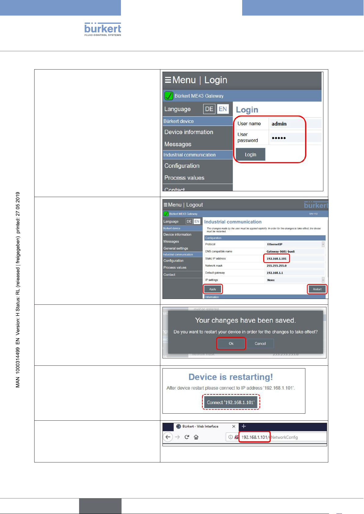
→ Complete the “User name” and “User
password”
(factory setting for both: “admin”)
→ Click the “Login” button
Type 8681 büS/CANopen
büS/CAN open-Design
→ Change/overwrite the “Static IP address”,
e.g. with “192.168.1.101”
or another address, to distinguish the
gateways from each other
→ Confirm by clicking the “Apply” button
(If the button “Restart” is clicked, the new
“Static IP address” is not saved, only the
device will be restarted.)
→ Click the “OK” button to take over the new
“Static IP address” by restarting the device
(if “Cancel” is selected, the old “Static IP
address” remains active and is only taken
over at the next restart)
→ The following message appears
38
→ To connect the gateway to its new IP
address:
enter the new IP address (shown in the
figure above) into the browser address bar
and press “Enter”
english
Page 39
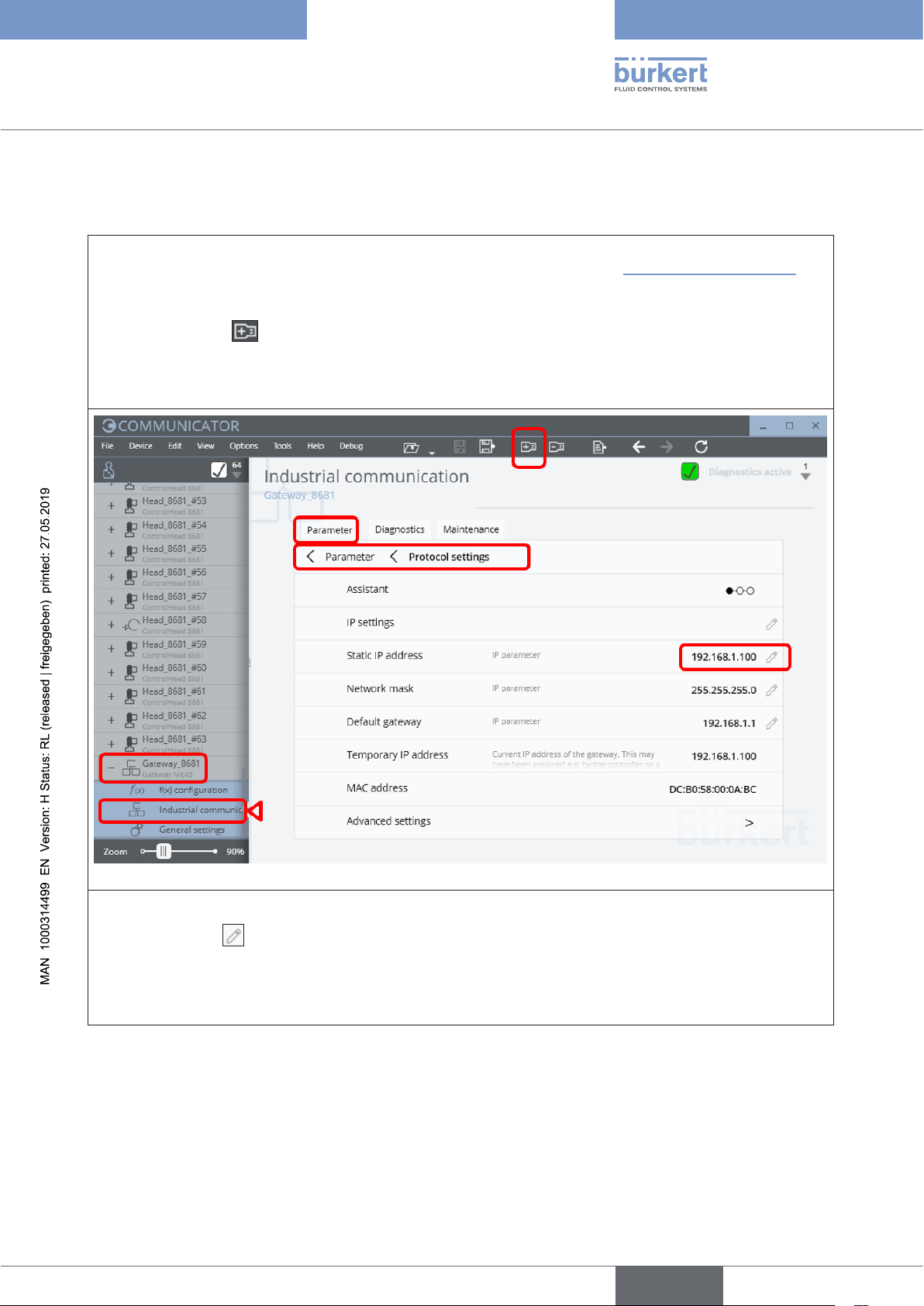
Type 8681 büS/CANopen
büS/CAN open-Design
6.14.2 Changing the gateway IP address using “Bürkert Communicator”
→ Connect the PC (with Bürkert Communicator Type 8920) via “büS stick” to the büS/CANopen data line
(e.g. to a free connection of a CAN junction box in the network - as shown in “Fig. 2: Network principle”)
→ Start the Bürkert Communicator Type 8920
→ Click on the icon to add a “büS connection” (e.g. “büS COM8”)
→ Open the desired gateway (e.g. “Gateway_8681”) and select “Industrial communication” and then the
“Parameter” tab, then select “Protocol settings”
→ The standard address “Static IP address” is displayed (“192.168.1.100”)
→ Click the pencil to change the IP address
→ Confirm the new “Static IP address” by clicking on the “Apply” button
→ Restart the device / gateway: Right click on “Gateway_8681”, then select the “Restart” option
english
39
Page 40
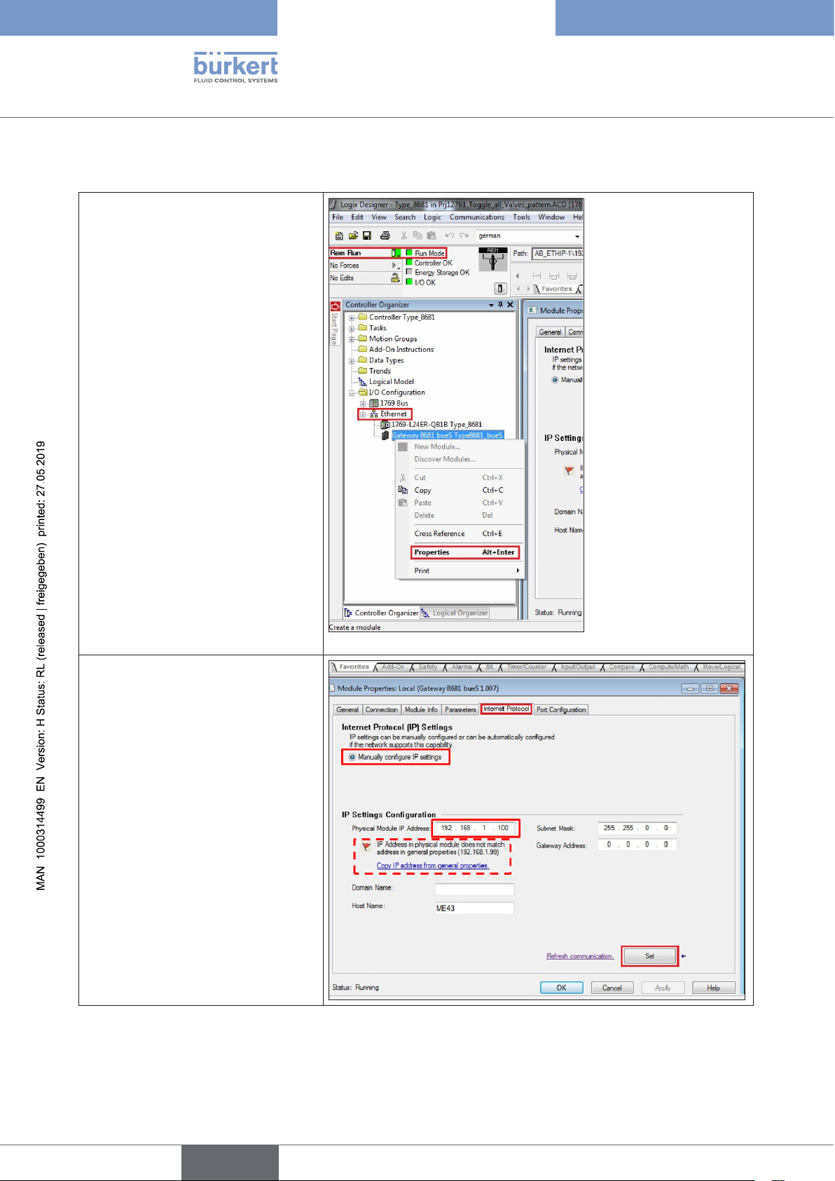
Type 8681 büS/CANopen
büS/CAN open-Design
6.14.3 Changing the gateway IP address via Logix Designer
→ Start the “Logix Designer”
→ First, select “Go Online”
(“Rem Run” = Remote Run)
→ Right click on “Ethernet”
→ Select “Gateway 8681 bues ...”
→ Right click and select “Properties”
→ A new window opens, go to the
“Internet Protocol” tab
→ Mark “Manually configure IP set-
tings” (in the area “Internet Protocol
Settings”)
→ In the area “IP Settings Con-
figuration”, overwrite the current
“Physical Module IP Address” and
- if required - also “Subnet Mask”
and “Gateway Address”
→ Click the “Set” button.
A warning then appears:
“IP Address in physical module
does not match address in general
properties (...)”
→ Click the “OK” button
40
english
Page 41
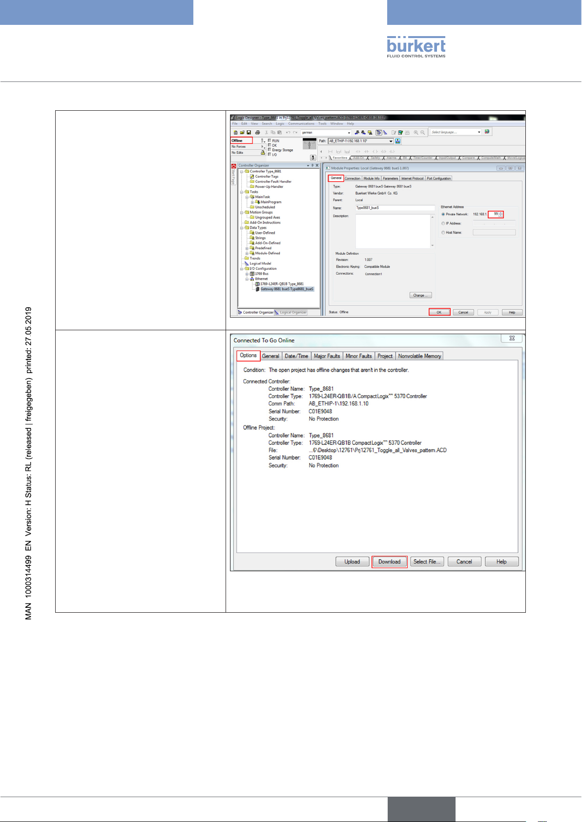
Type 8681 büS/CANopen
büS/CAN open-Design
→ Then select “Go Offline”
→ Go to the “General” tab
→ Overwrite the “Ethernet Address”/
“Private Network” with the new
address
→ Click the “OK” button
→ Select “Go Online” again
→ A new window opens
→ Go to the “Options” tab
→ Click the “Download” button to load
the offline changes of the project
into the controller / PLC
(continued on next page)
english
41
Page 42
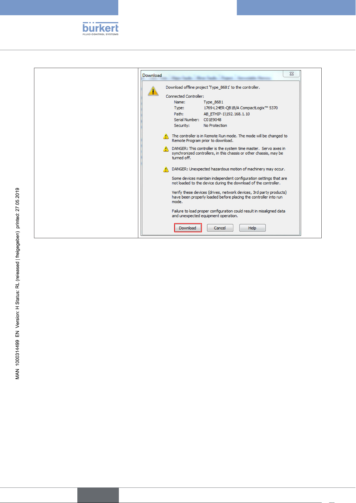
→ A new window with several
warnings opens
→ Click the “Download” button to
continue the download process
Type 8681 büS/CANopen
büS/CAN open-Design
42
english
Page 43
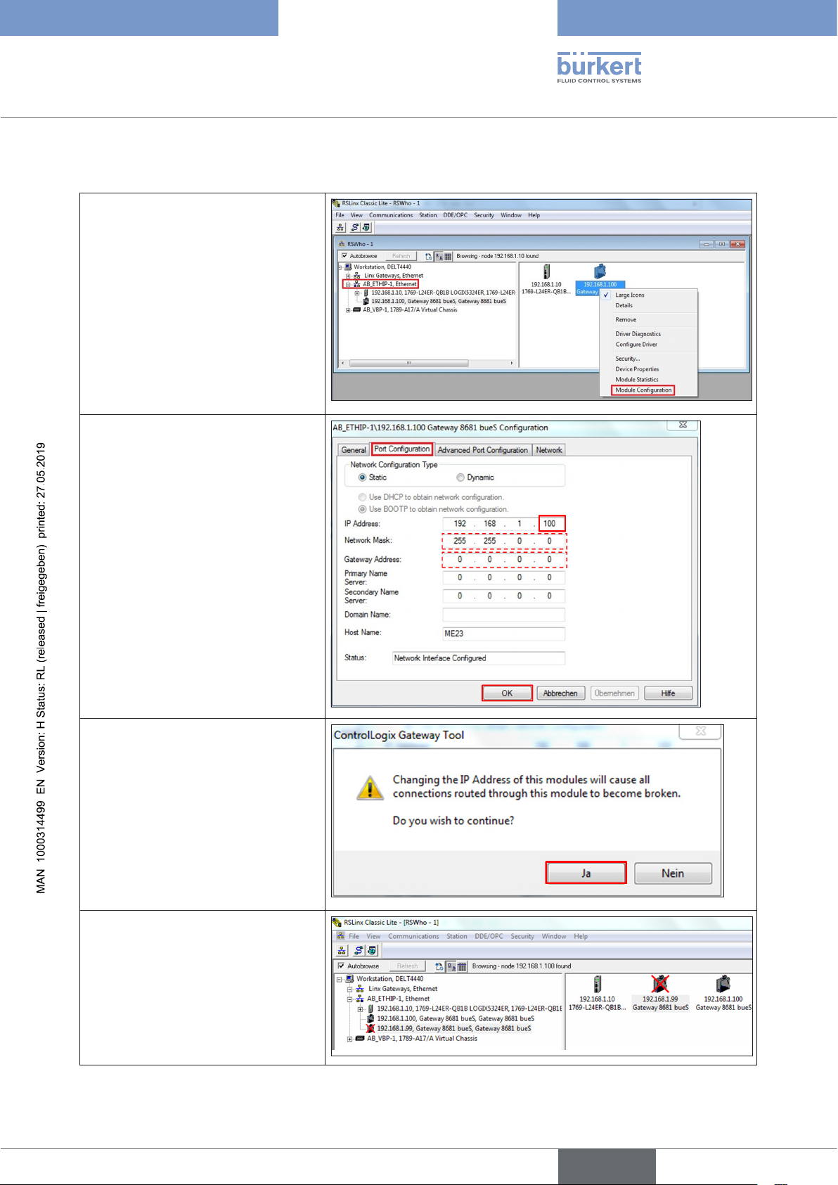
Type 8681 büS/CANopen
büS/CAN open-Design
6.14.4 Changing the gateway IP address using RS Linx
→ Start “RS Linx”
→ Select “Autobrowse”
→ Right click on “AB_ETHIP-1,
Ethernet”
→ Select “XXX, Gateway 8681
bueS ...”
→ Right click on “XXX, Gateway
8681 bueS ...” and select “Module
Configuration”
→ A new window opens, go to the “Port
Configuration” tab
→ In the area “Network Configuration
Type”, mark the “Static” option
→ Enter the new “IP Address” and - if
required - also the “Subnet Mask”
and “Gateway Address”
→ Confirm the configuration with “OK”
→ A warning window opens
→ Click “Ja” (Yes) button to continue
the changing process
Inaccessible IP addresses are crossed
out
43
english
Page 44
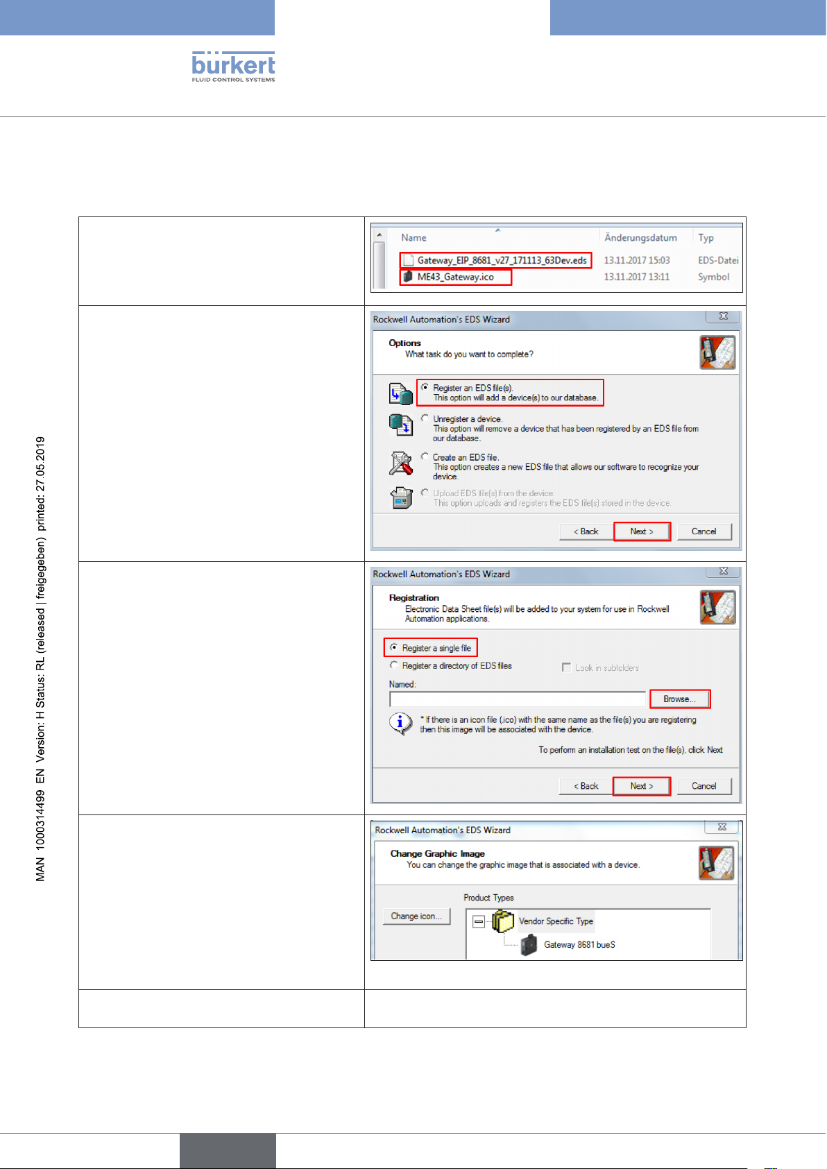
Type 8681 büS/CANopen
büS/CAN open-Design
6.15 Registration of a gateway via Logix Designer
The gateway ME43 must be registered in the Logix Designer database:
→ Ensure that the EDS file and the ICO file
are in the same folder
(Do not change the name of the ICO file
as it is referenced in the EDS file with this
name!)
→ Start the “Logix Designer”
→ Go to the “Tools” tab
→ Select “EDS Hardware Installation Tool”
→ A new window opens as shown in the figure
on the right
→ Select “Register an EDS file(s)” option and
click the “Next” button
→ A new window opens as shown in the figure
on the right
→ Select “Register a single file” option
→ Browse your computer for the appropriate
EDS file:
“Gateway_EIP_8681_vXX_
YYMMDD_63Dev.eds”
→ Click the “Next” button (twice)
→ A new window opens: “Change Graphic
Image”
→ If you want to change the icon graphic,
click the “Change icon ...” button and select
a graphic
→ Click the “Next” button (twice)
→ Then click the “Finish” button
44
The gateway ME43 is now registered in the
Logix Designer database.
english
Page 45
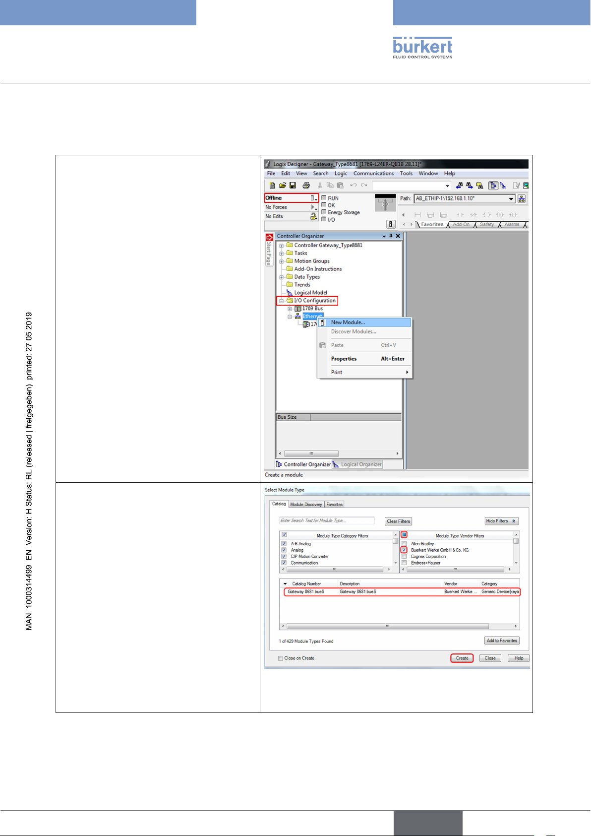
Type 8681 büS/CANopen
büS/CAN open-Design
6.16 Installation of a gateway via Logix Designer
Gateway(s) must be added to the Ethernet (I/O Configuration):
→ Start the “Logix Designer”
→ First, go “Offline”
→ Search for “I/O Configuration” and “Ethernet”
→ Right click on “Ethernet”
→ Select “New Module”
→ In the new window “Select Module Type”,
select the appropriate device from the
“Catalogue”:
(use the filter function for a faster search:
vendor “Buerkert Werke ...”)
→ After selecting the “Gateway 8681 bueS”,
click on the “Create” button
(continued on next page)
45
english
Page 46
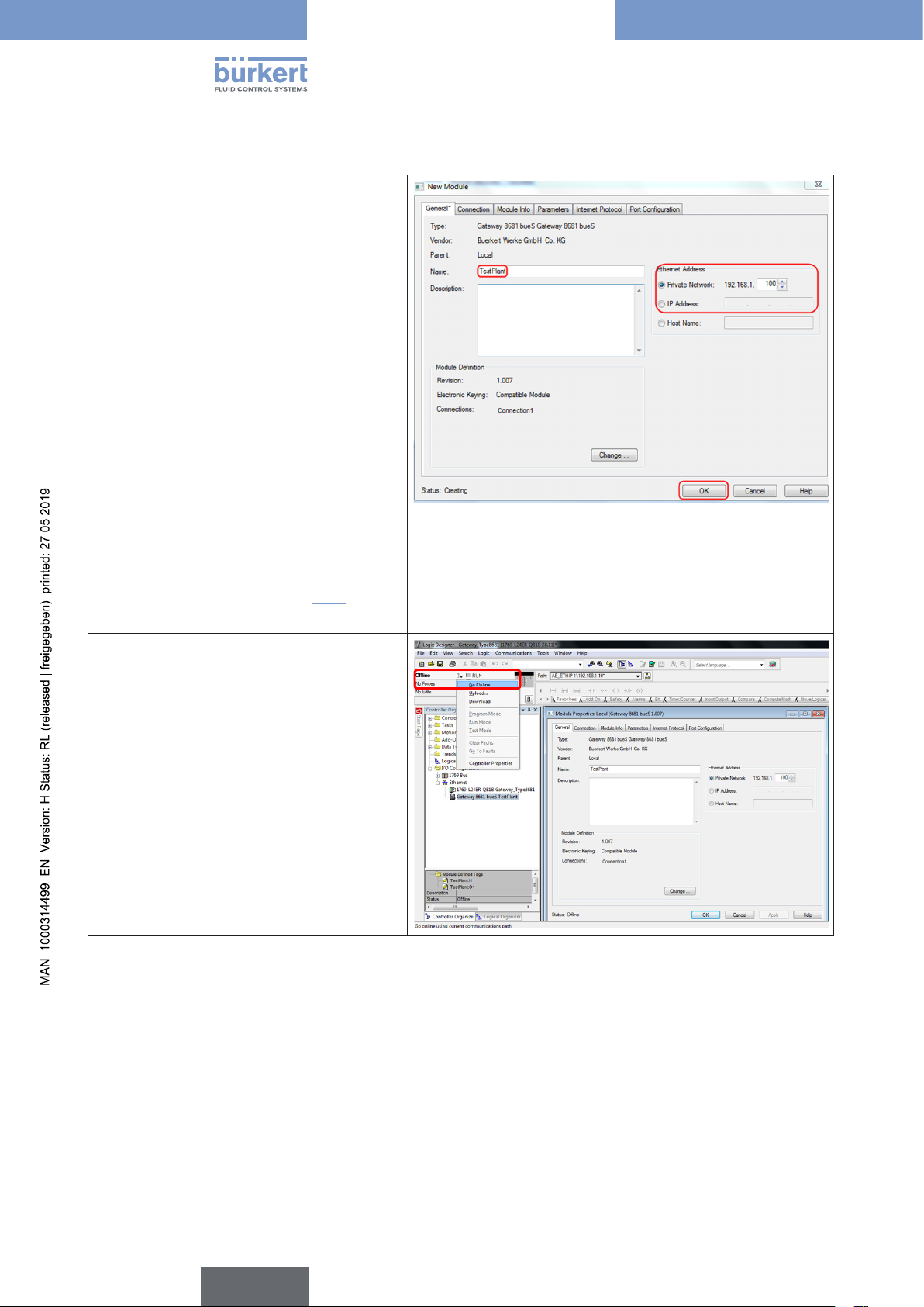
→ In the new window “New Module”, enter
a new significant name in the name field
and select the appropriate “Private
Network” number for the “Ethernet
Address”
→ Click on “OK” button
Type 8681 büS/CANopen
büS/CAN open-Design
→ Close the (old) window “Select Module
Type”
→ in the new window DOWNLOAD the cor-
responding files (see chapter “6.3”) onto
the PLC
→ Then “Go Online” to connect the gateway
and the master controller / PLC (EtherNet/
IP) to each other
46
english
Page 47
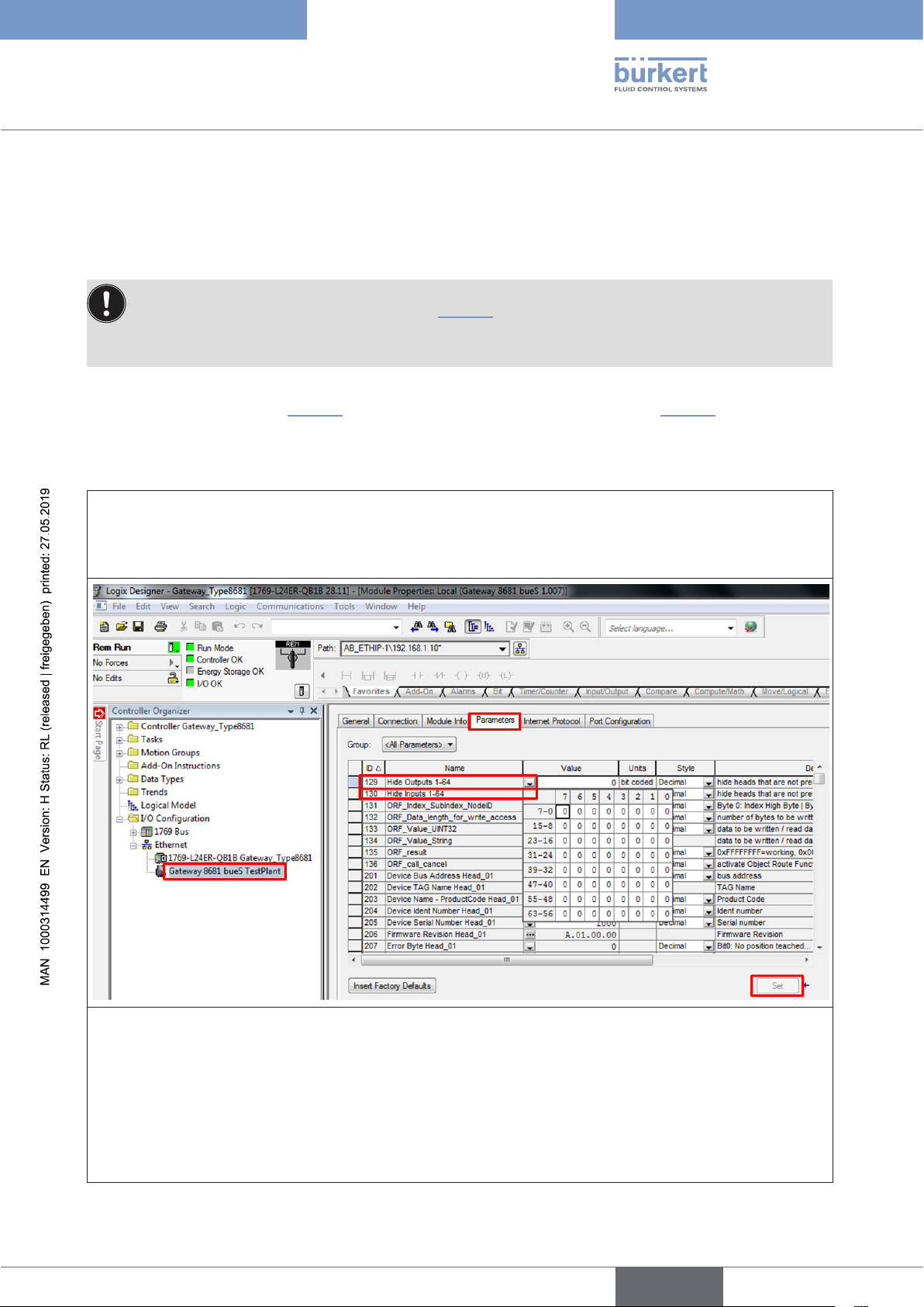
Type 8681 büS/CANopen
büS/CAN open-Design
6.17 Configuration of the control head network
The gateway Type ME43 is used as a fieldbus interface between the control heads (Type 8681 büS/CANopen) and
the master controller (EtherNet/IP). Each gateway can communicate with up to 63 control heads of Type 8681 büS/
CANopen.
To set up a network, it is necessary to assign a unique device address to each control head (to do so,
use the respective DIP switches - see chapter “6.13.2”).
If there are less than 63 control heads connected to a gateway, it is necessary to “hide” the nonexisting control heads, namely both the inputs and the outputs.
There are 2 options to “hide” the inputs and outputs:
via software “Logix Designer” (“6.17.1”) or via the “Bürkert Communicator” Type 8920 (“6.17.2”).
6.17.1 “Hide function” via software “Logix Designer”
→ Start the “Logix Designer”
→ Open the project (e.g. “Logix Designer - Gateway_Type8681”)
→ Open the desired gateway and select the “Parameters” tab
→ Now select the line “Hide Outputs 1-64” and “hide” each non-existent control head by setting a “1” (one) in
each field for the outputs.
→ Now select the line “Hide Inputs 1-64” and “hide” each non-existent control head by setting a “1” (one) in
each field for the inputs.
→ Click on the “Set” button to save it and to transfer it to the gateway
→ After doing these steps, restart the whole system: it is recommended to switch off and switch on the cor-
responding power supply unit! The network configuration has then been completed.
english
47
Page 48
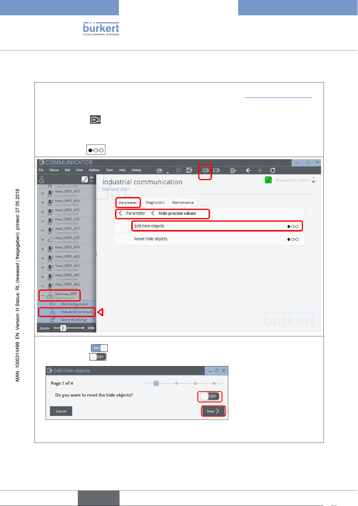
Type 8681 büS/CANopen
büS/CAN open-Design
6.17.2 “Hide function” via “Bürkert Communicator”
→ Connect the PC (with Bürkert Communicator Type 8920) via “büS stick” to the büS/CANopen data line (e.g.
to a free connection of a CAN junction box in the same network - as shown in “Fig. 2: Network principle”)
→ Start the Bürkert Communicator Type 8920
→ Click on the icon to add an interface (e.g. “büS COM8”)
→ Open the desired gateway (e.g. “Gateway_8681”) and select “Industrial communication” and then the
“Parameter” tab, search for “Hide process values”, then select “Edit hide objects” and start the
step sequence with a click
48
→ “Page 1”: Start the “hiding function”:
set the switch to (ON) in order to reset already hidden values – or
set the switch to (OFF) in order to NOT reset already hidden values.
→ Click on “Next” (or cancel the “hiding process” via button “Cancel”).
english
Page 49
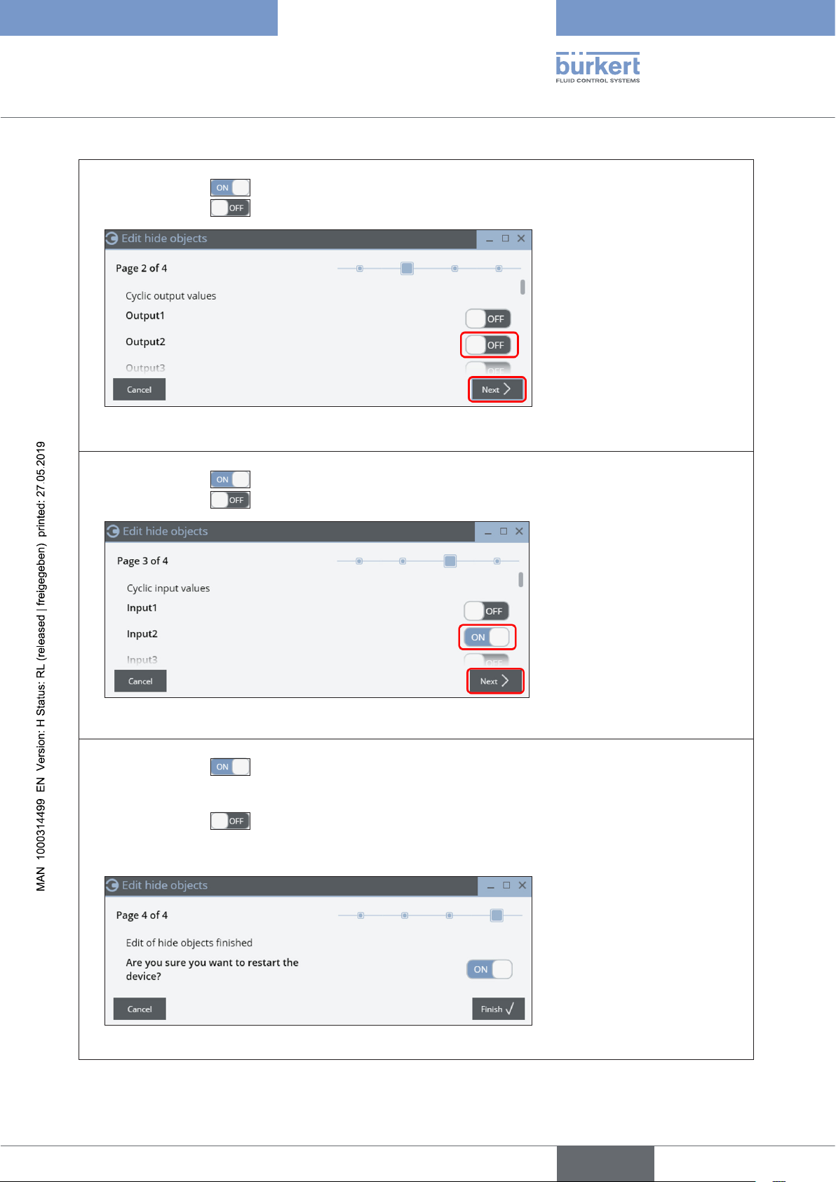
Type 8681 büS/CANopen
büS/CAN open-Design
→ “Page 2”: Hiding of the outputs:
set the switch to (ON) in order to activate the hiding, i.e. these outputs are hidden then – or
set the switch to (OFF) in order NOT to activate the hiding, i.e. these outputs are NOT hidden:
→ Click on “Next” (or cancel the “hiding process” via button “Cancel”).
→ “Page 3”: Hiding of the inputs:
set the switch to (ON) in order to activate the hiding, i.e. these inputs are hidden then – or
set the switch to (OFF) in order NOT to activate the hiding, i.e. these inputs are NOT hidden: :
→ Click on “Next” (or cancel the “hiding process” via button “Cancel”).
→ “Page 4”: Finish the “hiding function”:
set the switch to (ON):
newly hidden values will be confirmed and with “Finish” the device will be restarted immediately – or
set the switch to (OFF):
newly hidden values will be confirmed, but with “Finish” the device is NOT restarted immediately (the
newly set values are accepted after the next restart) – or
cancel the execution of the “hiding function” with button “Cancel” (so the new settings will be discarded).
49
english
Page 50
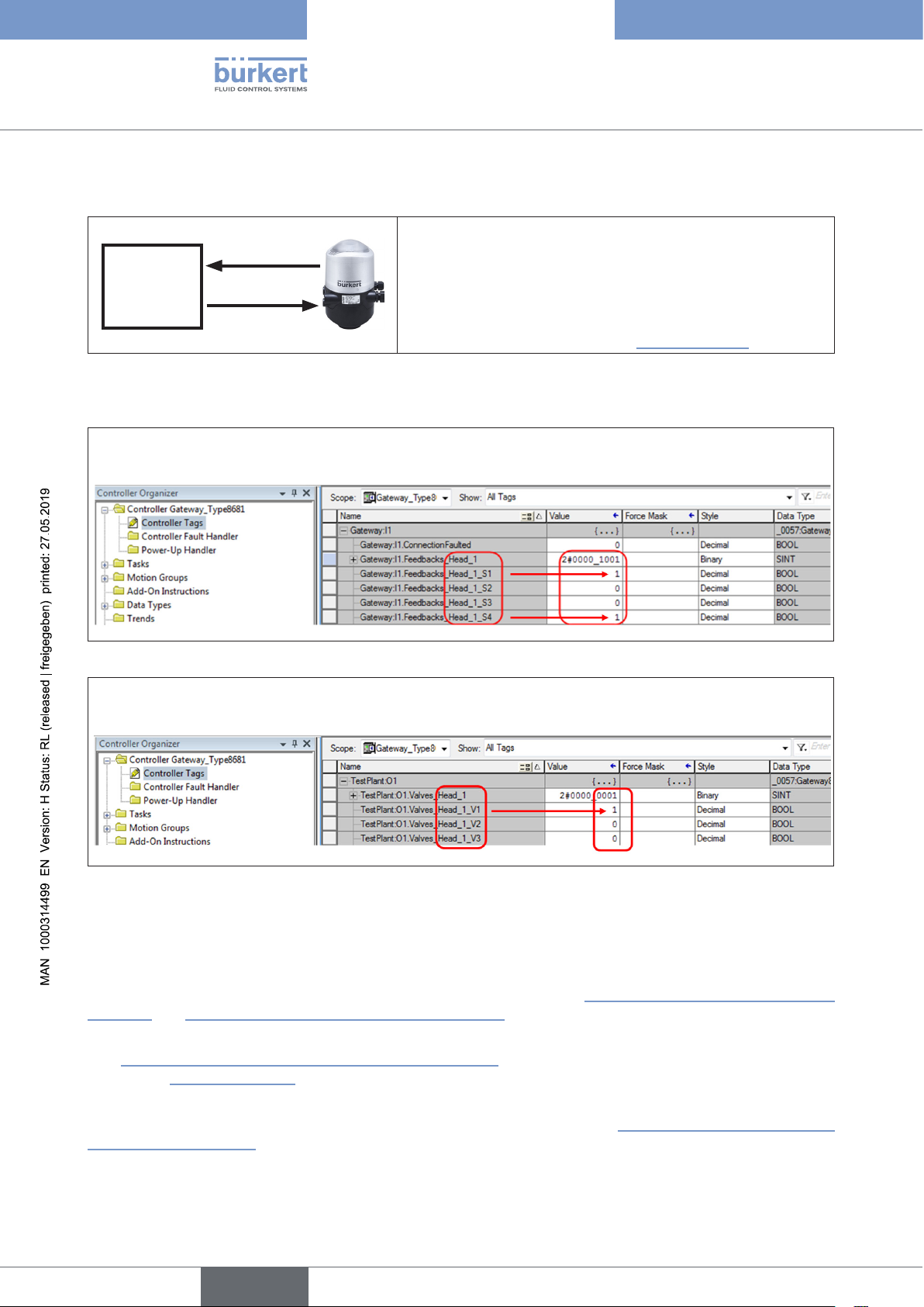
Type 8681 büS/CANopen
büS/CAN open-Design
6.18 Description of the (cyclical) I/O data
Depending on the configuration, the gateway processes
6 byte
Gateway /
SPS
The relevant process data are transfered via Logix Designer as “Controller Tags”:
the (position) feedback signals from S1 ... S4 (bit-coded, see example 1 below) and the current position feedback
signals (“analog”) as well as the solenoid valve switching states V1 ... V3 (bit-coded, see example 2 below)
Example 1 (process data from control head to gateway/PLC):
“Position 1” and “External Initiator” are active:
Process data
1 byte
1 ... 6 byte of the process data emanating from the control head
for the position feedback of the position measuring system.
1 byte process data regarding the solenoid valve switching
states are processed by the control head.
For process data, see also chapter “6.5” on page 27
Example 2 (process data from PLC/gateway to the control head):
“Valve 1” is active:
6.19 Access to parameters (Read / Write)
Some relevant acyclic parameters have been defined for preconfigured gateways which can be read directly with
the Logix Designer and partially overwritten - described below in chapters “6.19.1 Parameter – reading via Logix
Designer” and “6.19.2 Parameters – writing via Logix Designer”.
The Bürkert Communicator (Type 8920) also makes it easy to read out the parameters and change the values
(see “6.19.3 Access to parameters via Bürkert Communicator” or in the manual for the Bürkert Communicator -
see chapter “5.6.1” on page 24).
In addition to these relevant acyclic parameters, further values and states for acyclic parameters of the büS devices
connected to the gateway can be read out and partially written/overwritten - see “6.19.4 Access to further parameters (cyclic and acyclic)”.
50
english
Page 51
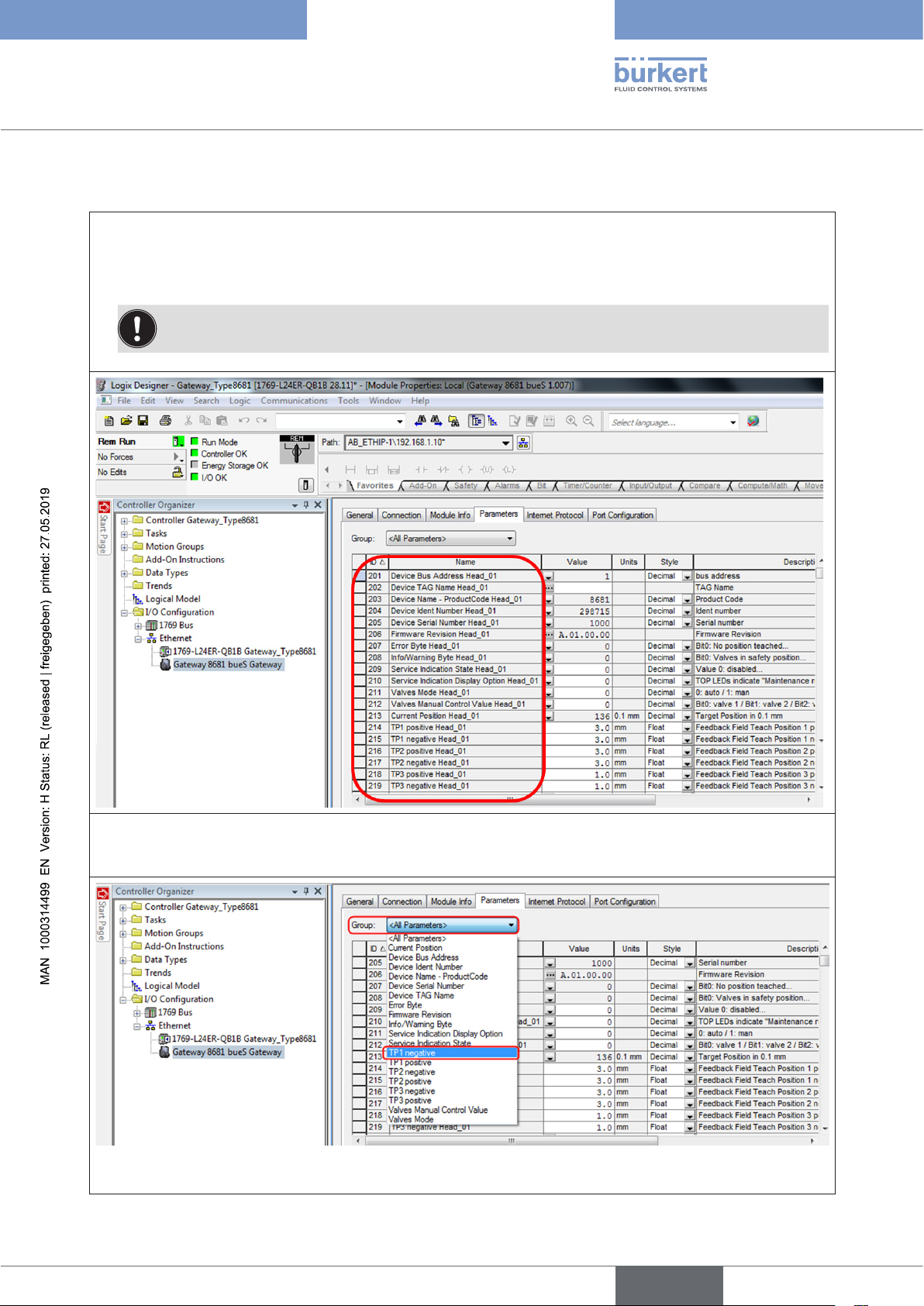
Type 8681 büS/CANopen
büS/CAN open-Design
6.19.1 Parameter – reading via Logix Designer
→ Open the project (e.g. “Logix Designer - Gateway_Type8681”)
→ According to the path (I/O Configuration / Ethernet / Gateway ...), open the desired gateway and
select the “Parameters” tab. In “Group” select <All Parameters>, all relevant predefined parameters
are displayed for each control head (scroll down to see the data of the other control heads).
NOTE! EDS with other predefined parameters available on request.
But o n e parameter for all control heads can also be displayed using the “Group” function:
→ E.g. select the (Parameter) “Group” / “TP1 negative” ( = Feedback Field Teach Position 1 negative):
T h i s parameter is displayed for all devices: (see next page)
51
english
Page 52
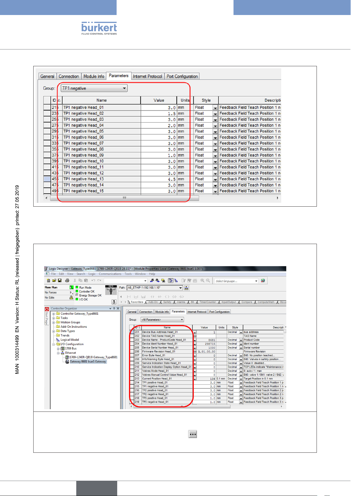
Type 8681 büS/CANopen
büS/CAN open-Design
6.19.2 Parameters – writing via Logix Designer
Parameters in white fields (rw) can be overwritten (parameters in grey fields (ro) can only be read out):
→ Open the desired gateway as for the reading function and in the “Parameters” tab select e.g. Group: “All
Parameters”
52
In order to type in or change a value in a white field:
→ Type in a value in the white “Value” field, considering the data type as specified under “Style” (if no style is
specified, it is a string value, in that case click the symbol to type in).
→ Press the button “OK or “Enter” to accept the value
english
Page 53
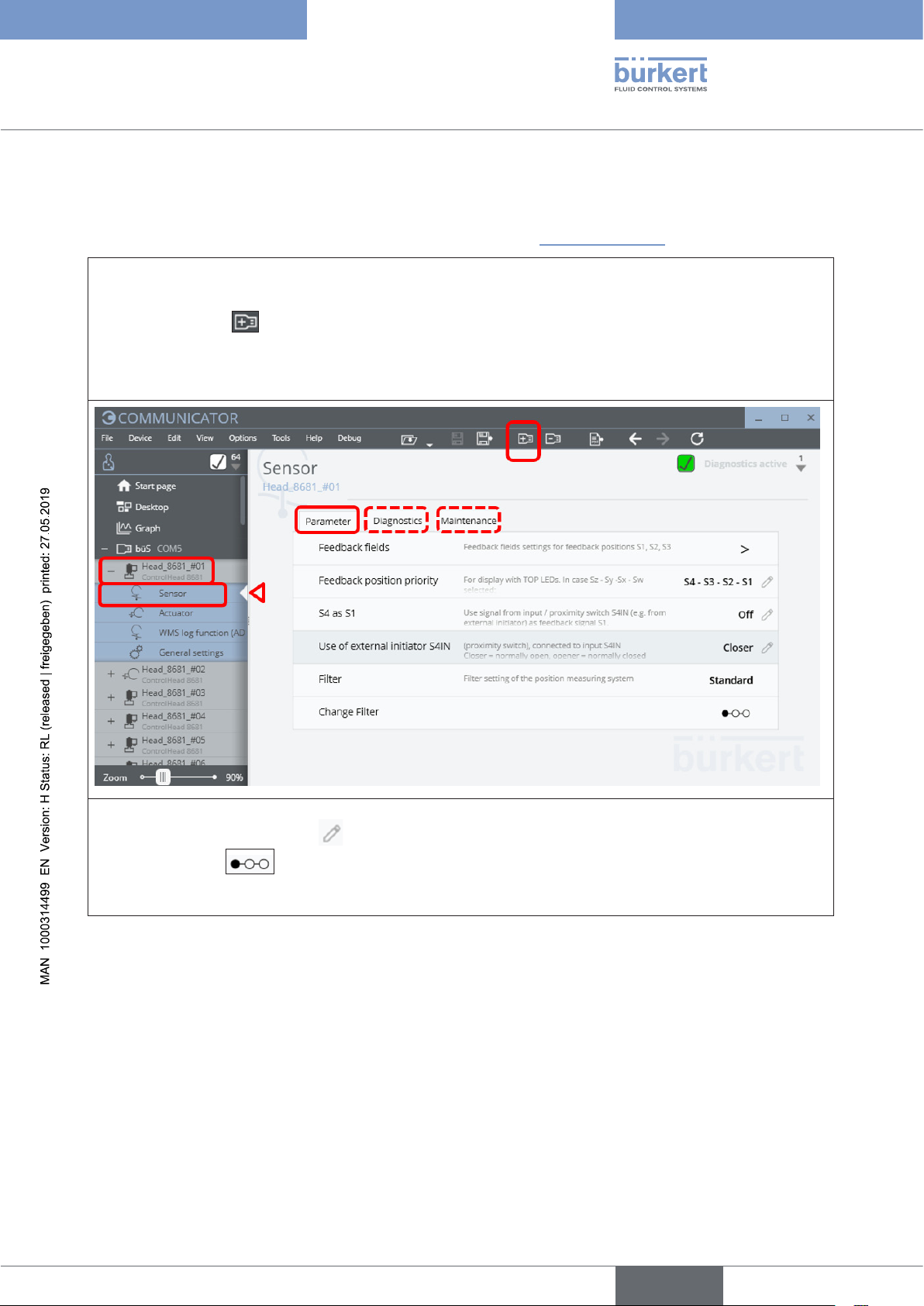
Type 8681 büS/CANopen
büS/CAN open-Design
6.19.3 Access to parameters via Bürkert Communicator
The Bürkert Communicator (Type 8920) makes it easy to read and change parameters. For a detailed description
of the Bürkert Communicator - see the relevant manual (see chapter “5.6.1” on page 24).
→ Connect the PC (with Bürkert Communicator Type 8920) to the büS/CANopen data line using the “büS stick”;
start Bürkert Communicator Type 8920
→ Click on the icon to add an interface (e.g. “büS COM8”)
→ Select the desired device in the navigation bar (left), open the “Parameter” tab (for special values also
“Diagnostics” or “Maintenance”), search for the desired value/parameter and read it out or change:
→ Current parameter values can be read out directly at the right margin;
Parameters with a pen symbol can be overwritten with the appropriate authorisation or
step sequences can be started.
→ A restart is required after a factory reset and in order to activate changes of bus/communication settings.
6.19.4 Access to further parameters (cyclic and acyclic)
In addition to the predefined relevant parameters, further values can be read out and partially overwritten. Access
is via “Bürkert Communicator” or e.g. via Logix Designer.
The required fieldbus addresses (as well as indices / sub-indices) are shown in a Parameter list that corresponds
to the respective gateway configuration. This parameter list and other files can be found on the Bürkert website -
enter the respective ID number of the preconfigured gateway as search term and download the required files from
the ZIP container under “Downloads” / “Software”.
An Object list for CANopen and other required files for the Type 8681 büS/CANopen can be found on the Bürkert
website – enter the type “8681” or the ID number of the device as search term and download the corresponding
files after opening the ZIP container with the “Initiation Files”, found under “Downloads” / “Software”.
53
english
Page 54
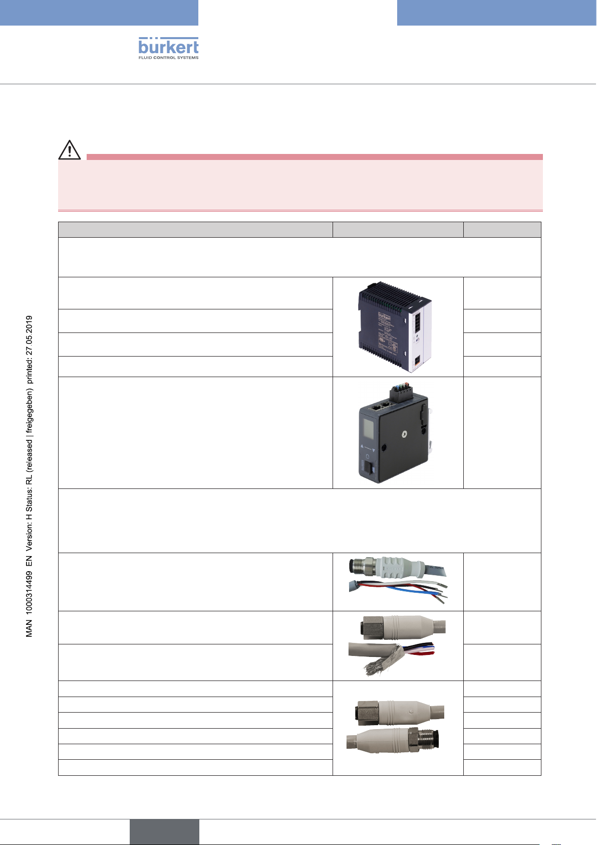
Type 8681 büS/CANopen
Accessories
7 ACCESSORIES
CAUTION!
Risk of injury and/or damage due to the use of unsuitable parts
Incorrect accessories and unsuitable spare parts may cause injuries and damage the device and the surrounding area.
` Use only original accessories and original spare parts from Bürkert.
Accessories Figure Order / ID no.
Switching power supply Type 1573 to power the CAN sub-system
(Note: only ID no. 772898 conforms to NEC Class 2
(all ID no. of Type 1573 conform to the EU standards 2014/35/EU - LVD and 2014/30/EU - EMC)
3.8 A nominal output current
(conforms to “NEC Class 2”)
1 A nominal output current 772361
772898
2 A nominal output current 772362
10 A nominal output current 772698
Gateway ME43 (also an SD card for the gateway)
(connection between büS/CANopen (Bürkert)
and Ethernet/IP (Rockwell Automation));
preconfigured and designed for the connection/control of up
to 63 Control Heads Type 8681 (büS)
Other pre-configurations e.g. in conjunction with Control
Heads Type 8691, Positioners Type 8692 or Process Controllers Type 8693 on request.
Cables and connections (büS/CANopen)
developed for application in environments with “hygienic requirements”
(degree of protection: IP65/67 | materials: Metal parts - stainless steel, cable sheath - PVC | U = 24 V DC,
I = max. 4 A;
required tightening torque for the required leak-tightness against moisture: 0.6 Nm + 0.1 Nm)
Connection cable with flying leads and M12 plug*), length 1 m
(for the connection of büS control heads with cable glands)
Connection cable with flying leads and M12 socket*),
length 1 m
316696
(gateway)
774087
(SD card)
218187
773482
54
Connection cable with flying leads and M12 socket*),
length 3 m
Extension cable, M12 plug + M12 socket*), length 0.5 m
Extension cable, M12 plug + M12 socket*), length 1 m
Extension cable, M12 plug + M12 socket*), length 3 m
Extension cable, M12 plug + M12 socket*), length 5 m
Extension cable, M12 plug + M12 socket*), length 10 m
Extension cable, M12 plug + M12 socket*), length 20 m
english
773483
773484
773485
773486
773487
773488
773489
Page 55
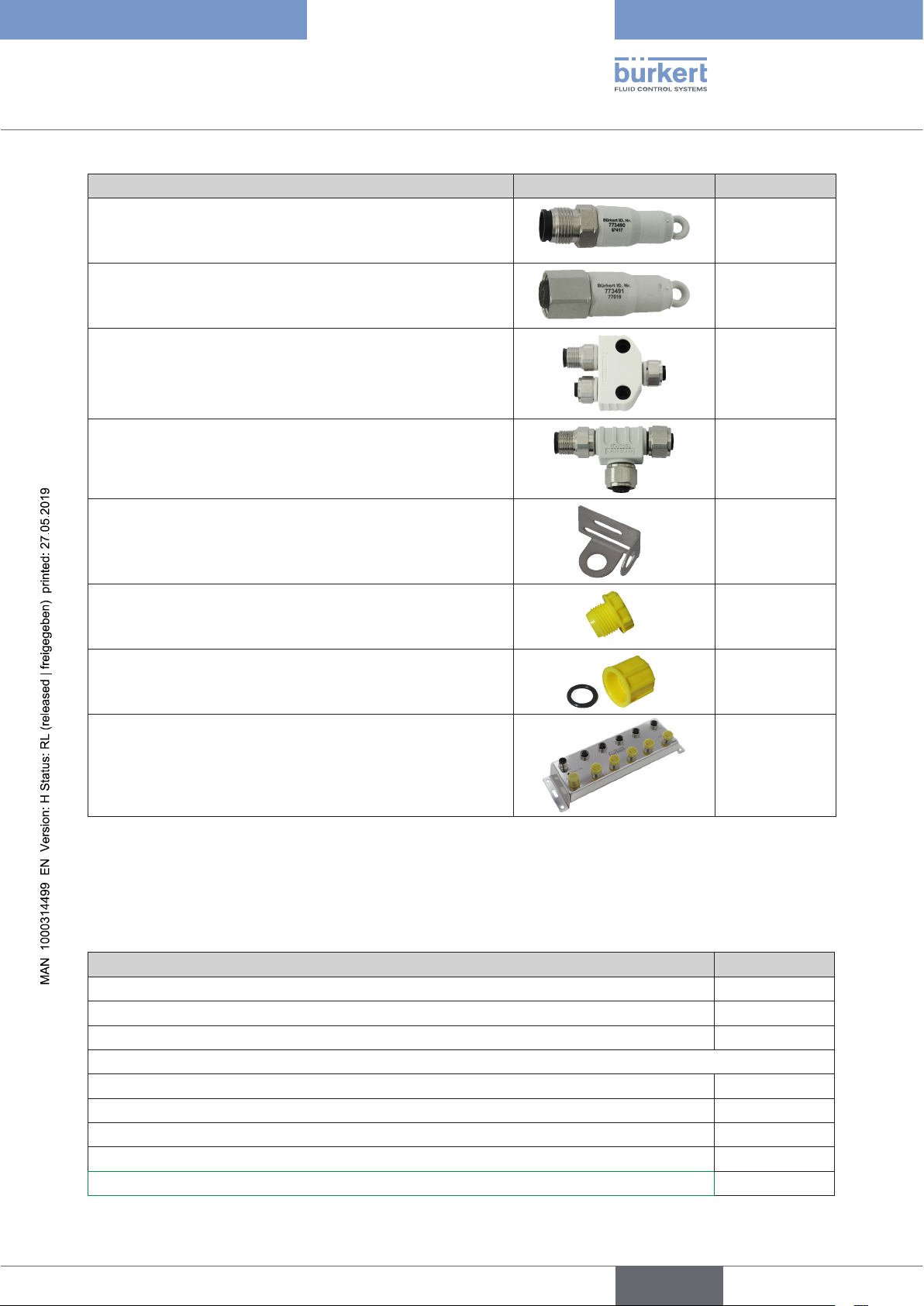
Type 8681 büS/CANopen
Accessories
Accessories Figure Order / ID no.
CAN terminating resistor, M12 plug*), 120 Ω
773490
CAN terminating resistor, M12 socket*), 120 Ω
CAN Y-connector, M12
CAN T-connector, M12
*)
*)
773491
773492
773493
Mounting plate for CAN T-connector (M12) 773494
Protective cap for M12 socket
308778
for closing unnecessary (open) connections
(10 protective caps per pack)
Protective cap for M12 plug including O-ring 8 x 2 N-NBR 70
308785
(10 caps and 10 O-rings per pack)
for closing unnecessary (open) connections
CAN junction box, M12 *)
338398
for connection up to 8 devices to the bus
(6 connections have already been closed with appropriate
protective caps)
*)
Required tightening torque for all plug-in connections (cables, T-pieces, ...) to ensure the required leak-
tightness against moisture: 0.6 Nm + 0.1 Nm.
Alternatively, DeviceNet cabling components (e.g. from Rockwell Automation) can also be used. However, they
must comply with the necessary requirements when used in the “Hygenic area”, because not all of these parts
have the required quality such as stainless steel or PP or PPE or PVC.
Service tool Order / ID no.
USB büS interface set:
büS standard set (büS stick + 0.7 m cable with M12 plug) 772551
büS adapter for büS service interface (M12 on büS service interface Micro-USB) 773254
büS cable extensions from M12 plug to M12 socket (not for “hygienic requirements”)
Extension cable, length 1 m 772404
Extension cable, length 3 m 772405
Extension cable, length 5 m 772406
Extension cable, length 10 m 772407
Equipment case “USB-büS-Interface Set1” 772426
55
english
Page 56
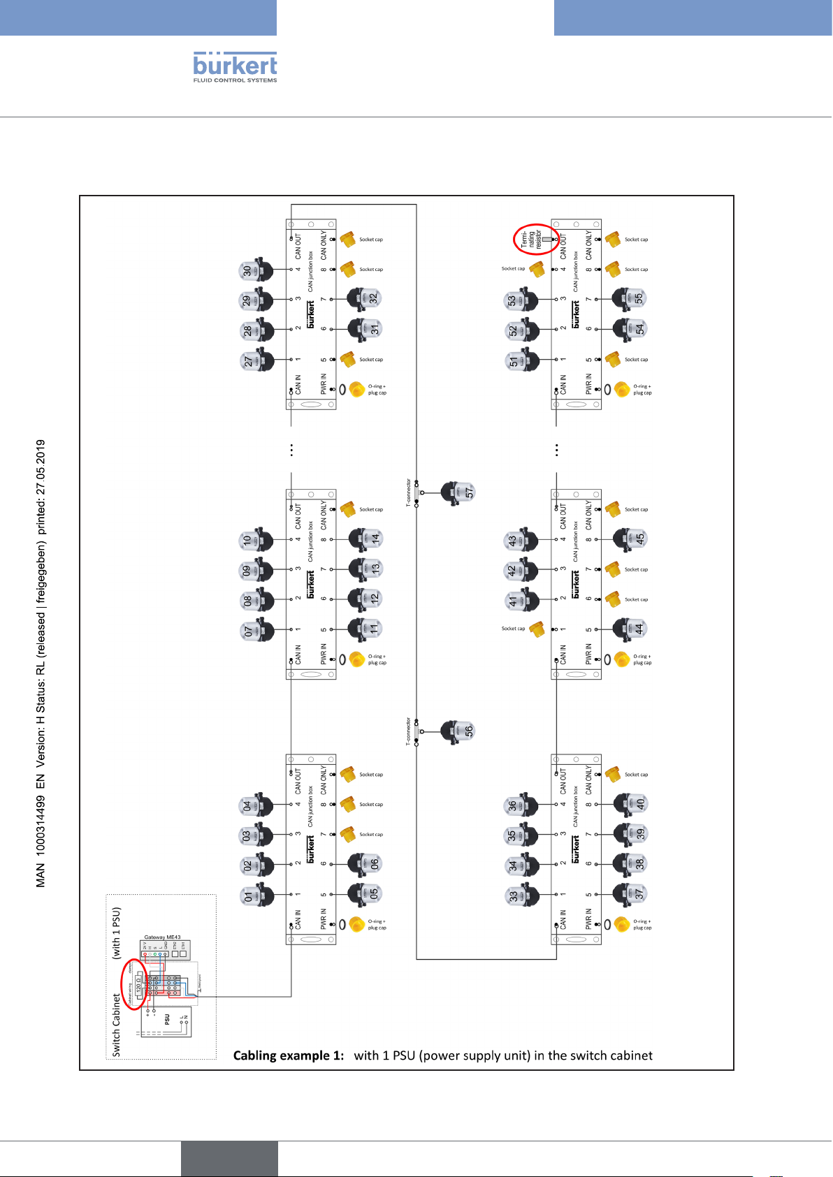
8 CABLING EXAMPLES
Type 8681 büS/CANopen
Cabling examples
56
Required tightening torque for all M12 connections (cables, T-pieces, ...),
to ensure the necessary tightness against moisture: 0.6 Nm + 0.1 Nm.
Close all open connections well with protective caps!
english
Page 57
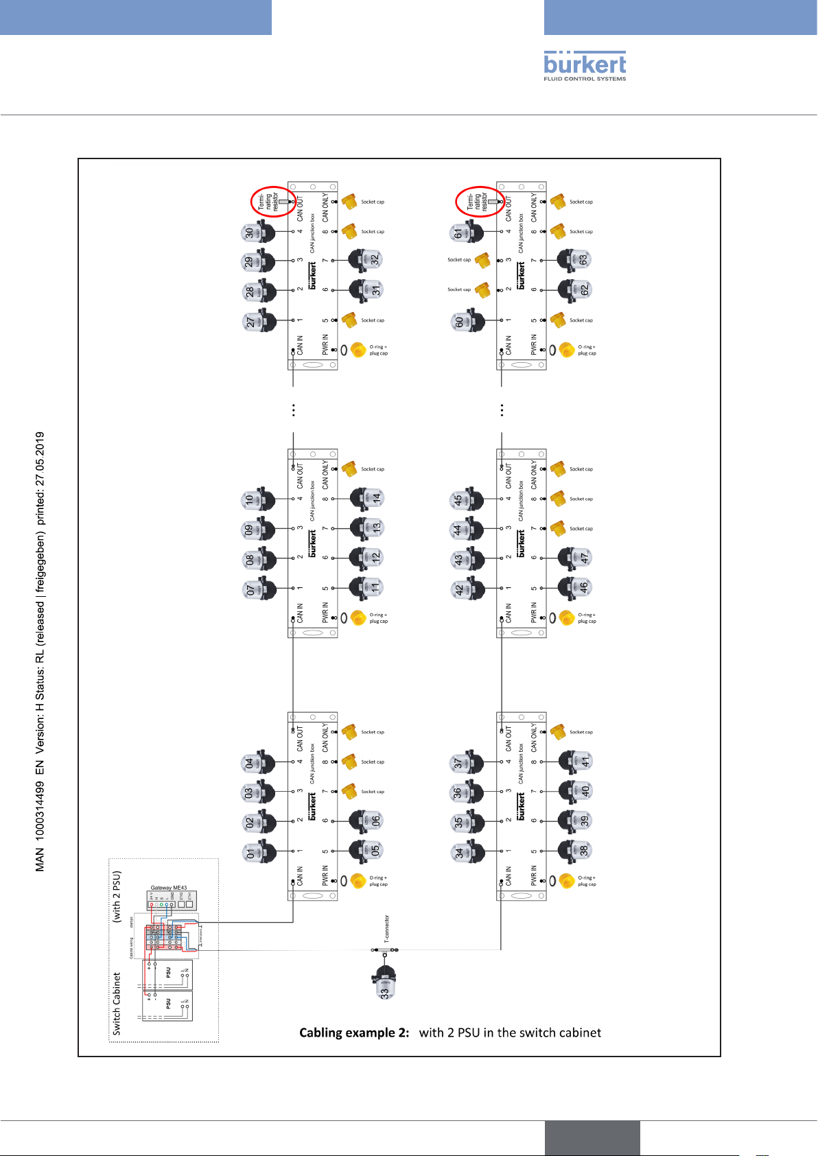
Type 8681 büS/CANopen
Cabling examples
Required tightening torque for all M12 connections (cables, T-pieces, ...),
to ensure the necessary tightness against moisture: 0.6 Nm + 0.1 Nm.
Close all open connections well with protective caps!
57
english
Page 58
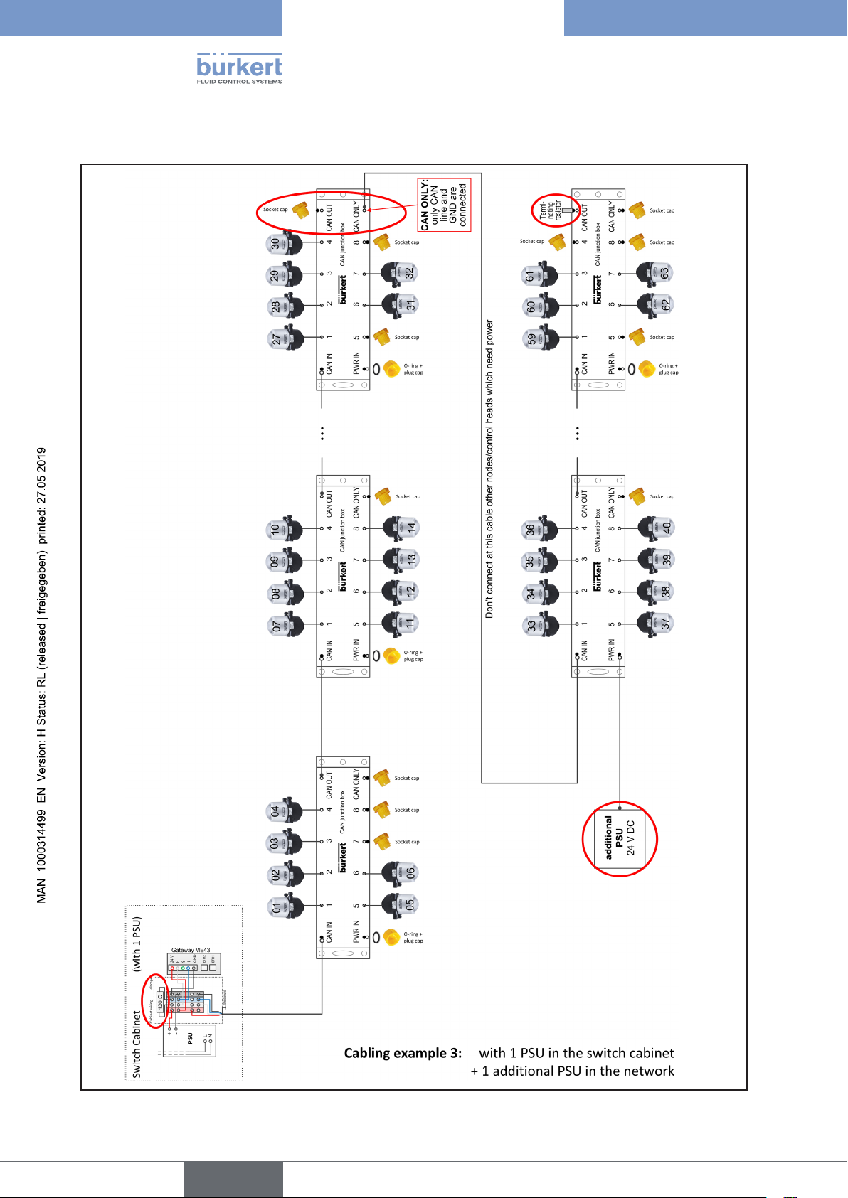
Type 8681 büS/CANopen
Cabling examples
58
Required tightening torque for all M12 connections (cables, T-pieces, ...),
to ensure the necessary tightness against moisture: 0.6 Nm + 0.1 Nm.
Close all open connections well with protective caps!
english
Page 59

Type 8681 büS/CANopen
english
59
Page 60
www.burkert.com
 Loading...