


 Loading...
Service Manual
Atria™ 3000
Electrocardiograph
Part No. 070-1133-00 Rev. A

TO RESPONSIBLE SERVICE PERSONNEL:
The contents of this document are not binding. If any significant differences between the product and this document are encountered regarding service work, contact Quinton Cardiology, Inc. for further information.
Quinton Cardiology, Inc. recommends the use of authorized Quinton Cardiology personnel for the maintenance and repair of all Burdick equipment. Quinton Cardiology, Inc. cannot warrant the operation of the equipment if other than Burdick genuine replacement or exchange parts are used in the service or repair of this equipment, and if such service or repair is performed by non-authorized personnel.
This product has been carefully designed to provide a high degree of safety and dependability. However, we can not guarantee against the deterioration of components due to aging and normal wear.
CAUTION — The Atria 3000 ECG is a restricted device. Federal law restricts the sale, distribution, or use of this device to, by, or on the lawful order of a health professional.
DANGER — Explosion hazard. Do not use this device in the presence of flammable anesthetics.
Copyright © 2005 Quinton Cardiology, Inc.
All rights reserved.
Quinton Cardiology, Inc. |
Authorized Representative |
|
3303 Monte Villa Parkway |
per MDD 93/42/EEC |
|
Bothell, Washington 98021-8969 |
MDSS |
|
(800) 426-0337 (425) 402-2000 |
||
Burckhardtstrasse 1 |
||
|
D-30163 Hannover, Germany |

Table of Contents
|
Warnings & Cautions . . . . . . . . . . . . . . . . . . . . . . . . . . . . . . . . . . . . . . . . . |
. iii |
|
Definitions of Symbols Used . . . . . . . . . . . . . . . . . . . . . . . . . . . . . . . . . . |
. . v |
Chapter 1 |
General Information . . . . . . . . . . . . . . . . . . . . . . . . . . . . . . . . . . . . . . . |
1-1 |
|
About the Atria Electrocardiographs . . . . . . . . . . . . . . . . . . . . . . . . . . . . |
1-1 |
|
Basic System Description . . . . . . . . . . . . . . . . . . . . . . . . . . . . . . . . . . . . . . |
1-1 |
|
Basic System Block Diagram . . . . . . . . . . . . . . . . . . . . . . . . . . . . . . . . . . . |
1-2 |
|
Technical Specifications . . . . . . . . . . . . . . . . . . . . . . . . . . . . . . . . . . . . . . . |
1-3 |
Chapter 2 |
Service & Maintenance . . . . . . . . . . . . . . . . . . . . . . . . . . . . . . . . . . . . |
2-1 |
|
What You Will Need . . . . . . . . . . . . . . . . . . . . . . . . . . . . . . . . . . . . . . . . . . |
2-1 |
|
Before You Begin . . . . . . . . . . . . . . . . . . . . . . . . . . . . . . . . . . . . . . . . . . . . . |
2-1 |
|
Preventive Maintenance . . . . . . . . . . . . . . . . . . . . . . . . . . . . . . . . . . . . . . . |
2-1 |
|
Visual Inspection . . . . . . . . . . . . . . . . . . . . . . . . . . . . . . . . . . . . . . . . . . . |
2-2 |
|
Cleaning . . . . . . . . . . . . . . . . . . . . . . . . . . . . . . . . . . . . . . . . . . . . . . . . . . |
2-2 |
|
Power Cable and Brick Cable . . . . . . . . . . . . . . . . . . . . . . . . . . . . . . . . |
2-2 |
|
Patient Cable . . . . . . . . . . . . . . . . . . . . . . . . . . . . . . . . . . . . . . . . . . . . . . |
2-2 |
|
Printhead . . . . . . . . . . . . . . . . . . . . . . . . . . . . . . . . . . . . . . . . . . . . . . . . . |
2-3 |
|
Service Function Menus and Options . . . . . . . . . . . . . . . . . . . . . . . . . . . . |
2-3 |
|
Setup Menu . . . . . . . . . . . . . . . . . . . . . . . . . . . . . . . . . . . . . . . . . . . . . . . |
2-3 |
|
Hidden Menu . . . . . . . . . . . . . . . . . . . . . . . . . . . . . . . . . . . . . . . . . . . . . . |
2-4 |
|
Special Functions Menu . . . . . . . . . . . . . . . . . . . . . . . . . . . . . . . . . . . . . |
2-5 |
|
Measuring Chassis Leakage Current . . . . . . . . . . . . . . . . . . . . . . . . . . . . |
2-7 |
|
Measuring Patient Leakage Current . . . . . . . . . . . . . . . . . . . . . . . . . . . . . |
2-8 |
Chapter 3 |
Problem Solving . . . . . . . . . . . . . . . . . . . . . . . . . . . . . . . . . . . . . . . . . . . . |
3-1 |
|
Troubleshooting . . . . . . . . . . . . . . . . . . . . . . . . . . . . . . . . . . . . . . . . . . . . . . |
3-1 |
|
Connector Pinouts . . . . . . . . . . . . . . . . . . . . . . . . . . . . . . . . . . . . . . . . . . . . |
3-4 |
|
Power In . . . . . . . . . . . . . . . . . . . . . . . . . . . . . . . . . . . . . . . . . . . . . . . . . . |
3-4 |
|
Power Supply Board . . . . . . . . . . . . . . . . . . . . . . . . . . . . . . . . . . . . . . . . |
3-4 |
|
Battery . . . . . . . . . . . . . . . . . . . . . . . . . . . . . . . . . . . . . . . . . . . . . . . . . . . . |
3-5 |
Chapter 4 |
Component Replacement. . . . . . . . . . . . . . . . . . . . . . . . . . . . . . . . . . |
4-1 |
|
Battery . . . . . . . . . . . . . . . . . . . . . . . . . . . . . . . . . . . . . . . . . . . . . . . . . . . . . . |
4-2 |
|
Top Enclosure . . . . . . . . . . . . . . . . . . . . . . . . . . . . . . . . . . . . . . . . . . . . . . . . |
4-3 |
|
Paper Drive Assembly . . . . . . . . . . . . . . . . . . . . . . . . . . . . . . . . . . . . . . . . |
4-4 |
|
Queue Sensor . . . . . . . . . . . . . . . . . . . . . . . . . . . . . . . . . . . . . . . . . . . . . . . . |
4-5 |
Atria Service Manual i

Power Supply Board and Power Supply Cover . . . . . . . . . . . . . . . . . . . |
4-6 |
Optional I/O Board and I/O Board Cover . . . . . . . . . . . . . . . . . . . . . . . |
4-7 |
Front End Digital Board . . . . . . . . . . . . . . . . . . . . . . . . . . . . . . . . . . . . . . . |
4-8 |
Parts Lists & Exploded Views . . . . . . . . . . . . . . . . . . . . . . . . . . . . . . . . . . |
4-9 |
Index . . . . . . . . . . . . . . . . . . . . . . . . . . . . . . . . . . . . . . . . . . . . . . . . . . . . . . . In-1
ii Atria Service Manual
Warnings & Cautions
Warnings
WARNING: There can be high voltage near the fuse, AC inlet and transformer. Always unplug the electrocardiograph before taking it apart.
Cautions
CAUTION: Always turn the electrocardiograph off and disconnect the power cord before cleaning. Do not pour liquids (such as alcohol or other cleaners) on the unit. This will cause severe electrical damage!
CAUTION: Setting the printhead resistance to any value other than the value written on the printhead will shorten the life expectancy of the printhead and may void your warranty.
CAUTION: Several of the electrocardiograph’s components are extremely sensitive to static electricity. To minimize the risk of damage, use a grounding strap and work on an antistatic surface.
CAUTION: The LCD is very sensitive to static electricity. Use an antistatic work surface.
CAUTION: The queue sensor is very sensitive to static electricity. Use an antistatic work surface.
CAUTION: The printhead is very sensitive to static electricity. Use an antistatic work surface.
CAUTION: The optional I/O board is very sensitive to static electricity. Use an antistatic work surface.
CAUTION: The front end digital board is very sensitive to static electricity. Use an antistatic work surface.
CAUTION: The power supply board is very sensitive to static electricity. Use an antistatic work surface.
Atria Service Manual iii

iv Atria Service Manual
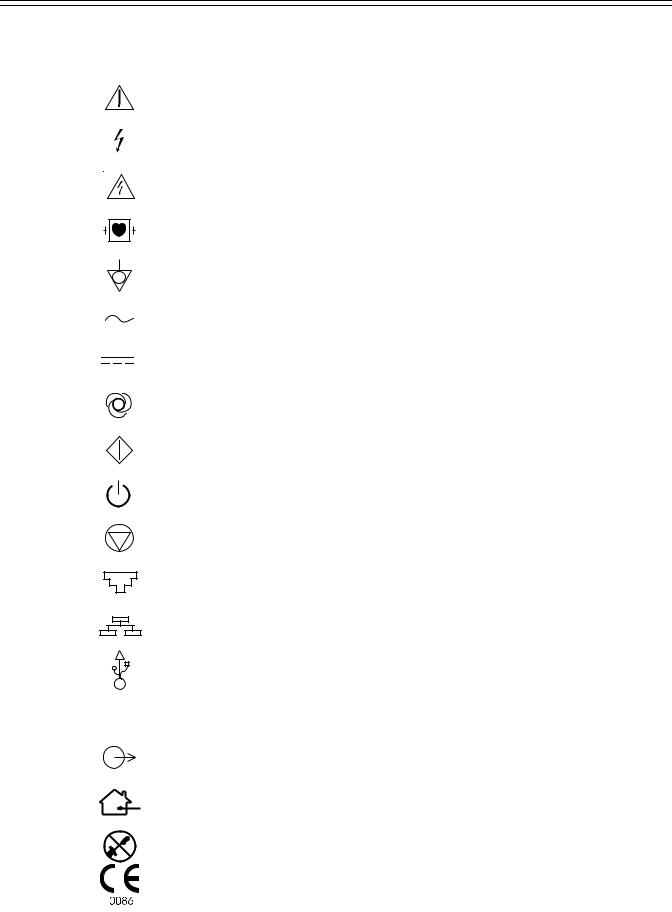
Definitions of Symbols Used
|
Attention. Consult accompanying documents. |
|
Danger! High voltage. |
|
Hazardous voltage. |
|
Defibrillation-Protected Type CF Equipment. |
|
Equipotentiality (used to label the grounding lug). |
|
Alternating Current (AC). |
|
Direct Current (DC). |
|
Automatic Operation. |
|
Manual Operation. |
|
On/Standby. |
|
Stop Function. |
|
Modem port. |
|
Ethernet port. |
|
USB port. |
I0I0 |
Serial port. |
Analog port.
Indoor, dry location use only.
No serviceable parts inside.
Meets or exceeds Council Directive 93/42/EEC, MDD, Class IIa.
Atria Service Manual v

Certified for both the U.S. and Canadian markets, to the applicable U.S. and Canadian safety standards.
Component is certified for both the U.S. and Canadian markets, to the applicable U.S. and Canadian safety standards.
Device or component is certified for the Japanese and/or Asian markets.
vi Atria Service Manual
|
|
|
1 |
|
|
|
|
|
|
|
|
|
|
|
|
|
|
Chapter |
|
|
General Information |
||
|
|
|
|
|
|
|
|
|
|
|
|
About the Atria Electrocardiographs
The Atria ECG is a multichannel non-interpretive/interpretive electrocardiograph. You operate the electrocardiograph by pressing various keys on the keypad. A thermal printer makes hard copy printouts of text and waveforms for permanent records.
The servicing of the Atria electrocardiograph is similar regardless of which model you have. Some of the information in this Service Manual applies only to options which you may or may not have installed in your electrocardiograph. Unless otherwise specified, the information in this Service Manual applies to the Atria electrocardiographs.
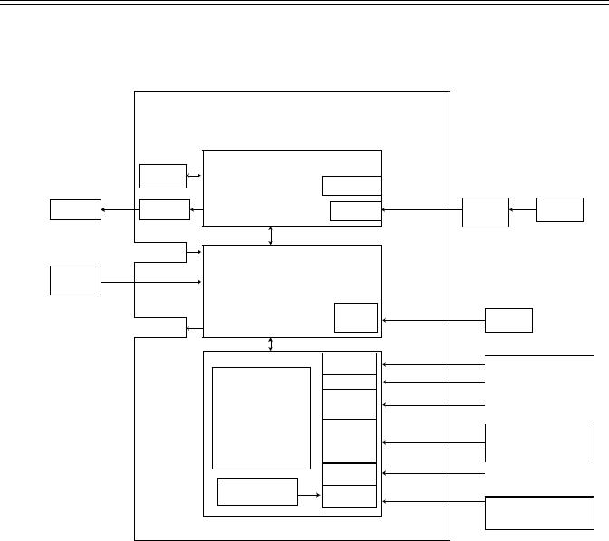
Basic System Description
A simple diagram of the system is shown in Figure . When AC power is not connected, an internal 14.4 V NiMH battery provides power for all functions. This battery is recharged whenever the AC line is connected.
The ECG data is acquired by hybrid circuits and sophisticated software on the Logic board. Under microprocessor control, the electrocardiograph samples, buffers and amplifies the analog ECG signals before converting them to digital levels for further processing. Input/output control circuitry handles communication with the front end ECG signals, LCD (liquid crystal display), membrane switches, thermal printer and external devices (if equipped).
Atria Service Manual 1-1
Chapter 1 General Information
Basic System Block Diagram
|
Atria 3000 |
|
|
|
|
Power Supply/Printer |
Board |
|
|
|
Battery |
Equipotential |
|
|
|
|
|
|
|
Paper |
Printer |
|
Isolation |
AC Power |
Power In |
Supply |
|||
|
|
|
(Brick) |
|
|
KeyBoard |
|
|
|
Patient |
|
|
|
|
Cable |
Atria Main Board |
|
|
|
|
|
|
||
|
(Front end and Host processor) |
|
|
|
|
|
Upgrade |
|
|
|
|
Compact |
Software |
|
|
|
|
|
|
|
LCD |
Flash |
Upgrades |
|
|
|
|
||
|
Optional I/O |
|
|
|
|
|
IRDA |
|
Printer |
|
|
Analog Out |
|
1mV =1V out/ |
|
|
|
Diagnostic equipment |
|
|
|
|
|
|
|
|
RS232 |
|
External Modems |
|
|
|
Database Management |
|
|
|
|
|
|
|
I/O Board |
|
|
Systems |
|
|
|
|
|
|
|
Dual USB |
|
Software Upgrades |
|
|
|
Printers / Database |
|
|
|
Host |
|
|
|
|
|
Management Systems/ |
|
|
|
|
|
|
|
|
|
|
Wireless devices |
|
|
RJ45 |
|
Ethernet |
|
|
|
Printers/Database |
|
|
|
|
|
|
|
Optional Modem |
|
|
Management Systems |
|
RJ11 |
|
|
|
|
|
|
|
|
|
|
|
|
Analog Phone Lines |
|
|
|
|
Faxes /Database |
|
|
|
|
Management Systems |
1-2 Atria Service Manual
Technical Specifications
Technical Specifications
Dimensions:
Weight (unit only): Display: Keyboard:
Data Storage:
Power Requirements:
15.0" x 13.125" x 5.5" (381mm x 334mm x 140mm)
11 lbs (5 kg) (including external power supply)
Backlit 2 X 40 character LCD
Full alphanumeric keypad plus designated quick keys
4 records standard, optional upgrade to 40 or 80
AC operation |
115/230 V AC ±10%, 50/60 Hz at the external power |
|
source |
Battery operation |
14.4 V NiMH rechargeable battery pack |
Battery duration |
30 minutes continuous printing or 30 ECGs |
Printout: |
|
Printout device |
216 mm thermal dot array |
Paper dimension |
8.5" x 11" (US letter) |
|
210mm x 300mm (A4) |
Paper type |
Thermal sensitive (Burdick Assurance® or |
|
Heartline™ paper recommended) |
Chart speeds |
10, 25, 50 mm/sec |
Gain |
5, 10, 20 mm/mV Chest or Limb (may be split) |
Printout formats |
3, 4, 6 or 12 channels; additional rhythm formats |
Acquisition: |
|
Lead selection |
I, II, III, aVR, aVL, aVF, V1, V2, V3, V4, V5, V6 |
|
Supports Frank X,Y, Z; Nehb D,A,J; and Alternate |
|
Chest Lead (chest lead selection V2R through V9R, |
|
V7, V8, and V9) |
Modes |
Automatic, automatic rhythm, or manual rhythm |
Frequency response |
Meets or exceeds ANSI/AAMI EC11-1991 standard |
Input impedance |
Meets or exceeds ANSI/AAMI EC11-1991 standard |
Electrode offset tolerance |
±300 mV |
Effective A/D resolution |
5µV LSB |
Artifact filter response |
40 Hz, -3db |
Data resolution |
500 samples/second, 5µV |
Pacemaker display capability |
Meets or exceeds ANSI/AAMI EC11-1991 standard |
Interpretation (optional) |
Diagnosis, measurements, reasons statements |
|
based on five demographic criteria |
Atria Service Manual 1-3

Chapter 1 General Information
Environmental:
Operating temperature |
50°F to 104°F (10°C to 40°C) |
Operating relative humidity |
10% to 95% non-condensing |
Operating atmospheric pressure |
1060 hPa to 700 hPa (-500 ft to 10,000 ft reference to |
|
sea level) |
Storage temperature |
-4°F to 131°F (-20°C to 55°C) |
Storage relative humidity |
25% to 95% non-condensing |
Storage atmospheric pressure |
1060 hPa to 190 hPa (-500 ft to 40,000 ft reference to |
|
sea level) |
Input/Output: |
|
(units with communications)
Conforms to Standards:
Safety:
Leakage current
Defibrillation protection
Equipment Type:
Warranty:
telephone line interface (RJ11)
Ethernet (RJ45)
USB type A
standard RS-232 (9 pin “D”)
analog output (3.5mm phono plug))
IrDA
CAN/CSA-C22.2 No. 0-M91 CAN/CSA-C22.2 No. 601.1-M90 CAN/CSA-C22.2 No. 601.1S1 CSA C22.2 No. 601.2.25
UL 2601.1
EN 60601-1
EN 60601-2-25 & Amend. 1, excluding 36202.5 EN 60601-1-2, excluding 36.202.6
AZ/NZS 2064.1/2 ANSI/AAMI EC11 - 1991
patient <10 µA, chassis <100 µA
to 5000V, 360J
Class IIa (Council Directive 93/42/EEC, MDD) IEC 601-1 Class I, Type CF
3 years with return of warranty card
1-4 Atria Service Manual
Loading...