

Page 1
INSTALLATION
INSTRUCTIONS
WWW.BURCAM.COM
2190 Boul. Dagenais West TEL: 514.337.4415
LAVAL (QUEBEC) FAX: 514.337.4029
CANADA
H7L 5X9 [email protected]
Your pump has been carefully packaged at the factory to prevent
damage during shipping. However, occasional damage may
occur due to rough handling. Carefully inspect your pump for
damages that could cause failures. Report any damage to your
carrier or your point of purchase.
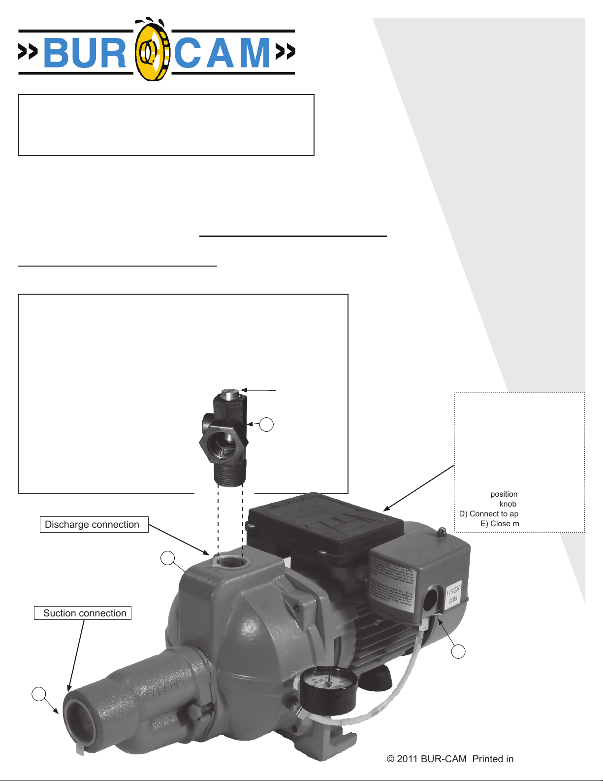
Use the included ow control valve to connect your pump to your home plumbing distribution
pipe system. Install this valve to the pump discharge and close the valve completely by
turning the top screw clockwise. Then, turn the screw counter-clockwise for one turn only
and proceed to the following priming process of the pump.
Follow all these inside step by step instructions to install your pump. Use teon tape on all
threads. (1) Install the pump discharge ttings as illustrated. (2) Fill the suction line with
water and connect it to the suction inlet. (3) Remove the priming plug and ll the pump body
with water. (4) Screw the plug to the priming inlet. (5) Turn the power on. The pump should
deliver water to the plumbing line within 30
seconds. If not, unplug the pump and repeat the
process at step 3.
After priming the pump, you can adjust the ow
control valve to obtain the best performance of
the pump. Remember that when you open this
valve, you reduce the suction capacity. This
valve is used to balance the discharge ow with
the suction requirement. The deeper your suction
distance, the more closed the valve should be for
optimum performance.
Discharge connection
Flo w c ont rol
valve
1
MODELS
503321/503721
AND
OTHER PRODUCTS
503327 503727
503328 503728
503331 503731
ETC.
JET PUMP
Please read these
instructions
carefully. Failure
to comply to
instructions and
designed
operation of
this system,
may void
the warranty.
FACTORY SET VOLTAGE 115 V
CONNECTION VOLTAGE
CHANGING:
Before changing the
voltage connection:
A) Ensure the power to
the pump is disconnected.
B) Open motor junction box cover.
C) Please select the up knob
position for 115V or down
knob position for 230V.
D) Connect to appropriate voltage.
E) Close motor junction box.
Suction connection
2
Priming plug
on the side.
3-4
5
© 2011 BUR-CAM Printed in Canada 510068
Page 2
Safety Instructions:
This ne pump that you have just purchased is designed from the latest in material and
workmanship. Before installation and operation, we recommend the following procedures:
A
B
C
D
CHECK WITH YOUR LOCAL ELECTRICAL AND PLUMBING CODES TO ENSURE YOU COMPLY
WITH THE REGULATIONS. THESE CODES HAVE BEEN DESIGNED WITH YOUR SAFETY IN MIND.
BE SURE YOU COMPLY WITH THEM.
WE RECOMMEND THAT A SEPARATE CIRCUIT BE LEAD FROM THE HOME ELECTRICAL
DISTRIBUTION PANEL PROPERLY PROTECTED WITH A FUSE OR A CIRCUIT
BREAKER. WE ALSO RECOMMEND THAT A GROUND FAULT CIRCUIT BE USED.
CONSULT A LICENSED ELECTRICIAN FOR ALL WIRING.
THE GROUND TERMINAL ON THE THREE PRONG PLUGS SHOULD NEVER BE REMOVED. THEY
ARE SUPPLIED AND DESIGNED FOR YOUR PROTECTION.
NEVER MAKE ADJUSTMENTS TO ANY ELECTRICAL APPLIANCE OR PRODUCT WITH THE
POWER CONNECTED. DO NOT ONLY UNSCREW THE FUSE OR TRIP THE BREAKER, REMOVE
THE POWER PLUG FROM THE RECEPTACLE.
Monthly Mandatory check-up:
1. Inspect the pump for any obvious condition that necessitates cleaning, correction, adjustement or repair.
2. Clear the surrounding of any paper, leaves or other debris.
3. Assure that the pump is secure for proper operation.
4. Assure that there is adequate clearance from any combustible materials or stucture. Stored materials
must be kept away from
the pump. Shelves or cabinet structures must not be in close proximity over the pump.
5. Assure that the motor is securely plugged into a proper GFCI electrical outlet
6. Test the GFCI outlet by pressing its test switch. This should prove that the outlet is energized and will trip
off to protect against a ground fault. Be sure to reset the GFCI by pressing its reset switch.
7. Observe that the plumbing can carry the water safely into the residence.
Material required for drilled well application (indoor use only)
Shallow well pump installation
Desired length of polyethylene 1” pipe, 100 PSI, CSA or UL
approved, to link up from pumping level to pump.
1 1” foot valve (750756 or 750752P).
1 well seal, as per well casing diameter
(750929 6” x 1”).
1 1” well seal elbow (750860).
2 1” male adaptors (750865 or 750871).
8 1” stainless steel clamps (750885).
Teon tape.
Tank installation
Desired length of 1” braided hose (750919) to link up from
pump to tank. Keep tank as close as possible from pump.
1 tank T (650651).
1 drain valve (650659).
2 1” female adaptor.
1 1” male adaptor (750865 or 750871).
3 1” stainless steel clamps (750885).
Teon tape.
2
Deep well pump installation
Desired length of polyethylene 1” and 1 1/4” pipe, 100 PSI,
CSA or UL approved, to link up from pumping level
to pump.
1 1” foot valve (750756 or 750752P).
1 well seal, as per well casing diameter
(750926 6” x 1 1/4” x 1”).
1 1” well seal elbow (750860).
1 1 1/4” well seal elbow (750861).
1 1 1/4” venturi adaptor (750864).
2 1” male adaptors (750865 or 750871).
1 1 1/4” male adaptor (750872).
8 1” stainless steel clamps (750885).
8 1 1/4” stainless steel clamps (750886).
Teon tape.
Tools
Screwdrivers, hacksaw to cut pipe, knife to assist in pipe
cutting, round le to smooth pipe ends, pipe wrench,
adjustable wrench to tighten ttings, propane torch and
welding material.
FOR INFORMATION TEL: 514.337.4415 FAX: 514.337.4029
Page 3
APPLICATIONS
FEATURES
• This pump is designed for shallow well installation
for water level up to 25 feet, with injector screwed on
pump body; or for deep well installation for water level
up to 85 feet, with 2 pipes and injector down in
the well.
• CAPACITY AT 20 PSI .
SHALLOW WELL DEEP WELL
1/2 HP 3/4 HP 1/2 HP 3/4 HP
5’ 900 950
10’ 800 850 30’ 500 525
15’ 650 700 40’ 400 425
20’ 450 500 50’ 300 325
25’ 300 350 80’ 150 175
US GPH US GPH
FRICTION LOSS IN PIPE
NOT INCLUDED.
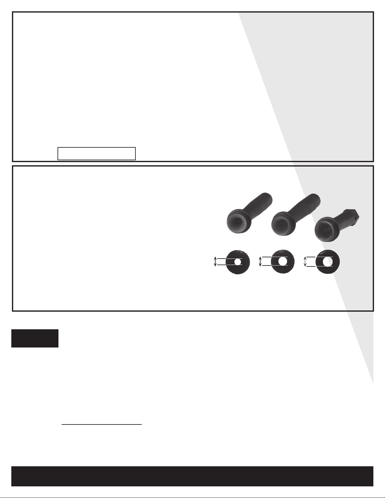
Your ejector is factory pre-assembled with the venturi
510066.2, for an optimum performance when the
pumping level is between 25’ to 60’ (7.5 meters to 18
meters) depth, in reference to the pump position.
So, this is a deep well application mode. The ejector is
positioned into the well and is connected to the pump
using 2 pipes (see page 5).
• High performance noryl impeller..
• Industrial motor totally enclosed, fan cooled.
• Full time connected run capacitor, to eliminate star-
ting wear vs regular motor.
• Thermal and overload protection.
• Built for a continuous use.
• 1/2 HP, 115/230 VCA, 60 Hz, 8.6 A/4.3 A.
• 3/4 HP, 115/230 VCA, 60 Hz, 8.9 A/4.5 A.
(at start : 15 A/7.5 A)
Factory
pre-assembled, for
For deep well
application mode,
60’ and deeper.
deep well application
mode, 25' à 60'.
For shallow
well application
mode.
If the pumping level is deeper than 60’ (18 meters)
in reference to the pump position, it is mandatory to
unscrew the pre-assembled venturi and to replace it
9/32"
510066.3
21/64"
510066.2
510066.1
31/64"
by the venturi 510066.3, also as a deep well mode
application with the ejector positioned into the well.
7.1mm
8.3mm
12.2mm
In the case of a pumping level lower than 25’ (7.5
meters), unscrew the pre-assembled venturi and replace
it by the venturi 510066.1. Then screw the
ejector to the pump body. This becomes a shallow well mode application where only one pipe is required
to pump water (see page 4).
INSTALLATION STEPS
We recommend that you install your pump in a clean and dry location where there is adequate room
STEP 1
for servicing at a later date. Protection from freezing temperatures and good ventilation should be
considered as well, to provide the pump an environment for long life. Locating the pump as close as
possible to the water source will reduce friction losses encountered in the suction pipe.
Friction losses in the suction pipe must be taken into consideration when the horizontal offset is greater
than 50 feet. The suction pipes should be increased from 1” to 1 1/4”. This will reduce friction losses and
allow the pump to give maximum performance.
A new well should be checked to determine that it is free from sand. Sand will damage the seal and the
impeller. Have your well driller clean the well before your installation.
Never run the pump dry. Damage to the seal may occur. Fill pump body and suction pipe with water
before turning on the power.
THE RUN OF HORIZONTAL PIPE FROM THE TOP OF YOUR WELL INTO THE HOUSE, WHERE
YOUR PUMP WILL BE LOCATED, MUST BE INSTALLED IN A TRENCH, BELOW THE FROST LEVEL
OF YOUR AREA.
FOR INFORMATION TEL: 514.337.4415 FAX: 514.337.4029
3
Page 4
DEEP WELL APPLICATION
SEE DIAGRAM ON PAGE 9
STEP 2
STEP 3
STEP 4
STEP 5
Locate your injector body in your package. Using teon tape, screw the 1 1/4” venturi adaptor
over the injector venturi (black tube), into the 1 1/4” opening of injector body. Install the 1”
male thread adaptor in the 1” opening in injector body. Securely tighten both adaptors with
pipe wrench.
With teon tape on threads, install a 1” nipple into the 1” foot valve, then screw this assembly
into the 1” bottom opening of the injector.
Cut the desired length of 1” and 1 1/4” poly pipes to run from the top of the well to the pumping
level. Smooth the pipe cuttings with your round le. (Check that no cut-out parts are left
inside of pipe. This may block pump injector or impeller). Slide 2 stainless steel clamps over
one end of each pipe and use torch to soften pipe. Fix the 1” and 1 1/4” pipes respectively
on the 1” adaptor and 1 1/4” venturi adaptor. Tighten clamps with screwdriver when cool.
For security against leaks, we suggest to install 2 stainless steel clamps on each
adaptor.
Insert both well seal elbows thru their opening of the seal. Slide 2 stainless steel clamps over
the free ends of the previously cut pipes and soften pipes with your torch. Attach pipes to the
well seal elbows (ends protruding at bottom of well seal). Tighten clamps with screwdriver
when cool.
To facilitate servicing at a later date, you may use a pitless adaptor and a sealed well cap
instead of an elbow and a well seal as describe in steps 3 and 4.
STEP 6
STEP 7
STEP 8
Install the well seal and the injector piping assembly into your well casing. Tight down the well
seal bolts using your adjustable wrench.
Install your pump in the house, on a sound foundation, as close as possible to the basement
wall. Locate the openings in the front of the pump body. Thread respectively 1” and 1 1/4”
adaptors into corresponding openings using teon tape. Do not over tighten.
Cut the desired length of pipes from pump location to the well seal and connect
both ends using the previous way, with stainless steel clamps and torch.
Do not ll in your trench to the house until you have checked for any leaks in your
connections or trouble in your water system.
CONTINUE ON PAGE 6 FOR TANKS
AND ON PAGE 7 FOR ELECTRICAL INSTALLATION STEPS.
4
FOR INFORMATION TEL: 514.337.4415 FAX: 514.337.4029
Page 5
STEP 2
STEP 3
STEP 4
SHALLOW WELL APPLICATION
SEE DIAGRAM ON PAGE 8
Cut the desired length of poly pipe to run from the top of the well to the pumping level. Smooth
the pipe cuttings with your round le. (Check that no cut-out parts are left inside of pipe. This
may block pump injector or impeller). Tape male adaptor threads with teon tape and thread
adaptor into the foot valve. Slide 2 stainless steel clamps over one end of pipe and use torch
to soften pipe. Insert the male adaptor and foot valve into this pipe end. Tighten clamps with
screwdriver when cool. For security against leaks, we suggest to install 2 stainless steel
clamps on each adaptor.
Insert the well seal elbow thru the opening of the seal.
Slide 2 stainless steel clamps over the free end of the previously cut pipe and soften pipe
with your torch. Attach pipe to the well seal elbow (end protruding at bottom of well seal).
Tighten clamps with screwdriver when cool.
Install the well seal and piping assembly into your well casing. Tight down the well seal bolts
using your adjustable wrench.
To facilitate servicing at a later date, you may use a pitless adaptor and a sealed well cap
instead of an elbow and a well seal as describe in steps 3 and 4.
STEP 5
STEP 6
STEP 7
for sand
or well
points
Install your pump in the house, on a sound foundation, as close as possible to the basement
wall. Locate the suction inlet in the front of the injector. Thread an adaptor into inlet using
teon tape. Do not over tighten.
Cut the desired length of pipe from pump location to the well seal and connect both ends
using the previous way, with stainless steel clamps and torch. Do not ll in your trench to
the house until you have checked for any leaks in your connections or trouble in your
water system.
Sand or well points are limited to areas where water bearing sand or gravel lies below the
surface, and where there are no boulders or rocks to interfere with the driving into the ground
of the point.
The amount of water any “one” well point will supply is usually rather limited. Sometimes, it is
necessary to use more than one point to increase the supply of water, entering to the pump’s
suction.
THE IMPORTANT INSTALLATION STEP IN USING WELL POINTS IS THAT A CHECK
VALVE MUST BE USED IN THE SUCTION PIPE LEADING TO THE SUCTION INLET,
AS CLOSE TO THE PUMP AS POSSIBLE, TO KEEP SUCTION LINE AND PUMP WELL
PRIMED.
CONTINUE ON PAGE 6 FOR TANKS
AND ON PAGE 7 FOR ELECTRICAL INSTALLATION STEPS.
FOR INFORMATION TEL: 514.337.4415 FAX: 514.337.4029
5
Page 6

STEP 8
for captive
air tanks
TANKS INSTALLATION
SEE DIAGRAM ON PAGE 10
Packaged systems have the pump mounted directly to the tank. The pump to tank plumbing
ttings are pre-assembled in factory. You only have to connect the discharge line of your
system to your home’s plumbing distribution line. When using a separate tank from your
pump, we recommend to install a captive air tank as shown in our typical installation diagram,
that is air injected into the tank at the factory. This air, which is in addition to atmospheric
pressure, increase the ability of the tank to deliver more water between on/off cycles, thus
increasing the efciency of your water system. Connect the pump discharge to the tank T,
using adaptors and braided hose, then, connect the other side of tank T to your home’s
plumbing distribution line.
Make sure that the precharged air pressure (before connecting the tank) is 2 PSI less
than the starting pressure setted on the pressure switch of your pump. If you adjust the
air pressure after the installation, follow these steps:
- Check the starting pressure of the pump on the pressure gauge;
- Disconnect the power to the pump;
- Open nearest fawcet to the tank and relieve all pressure in tank, then close
the fawcet;
- Adjust the air pressure of the tank (by pumping or removing air at the snifter valve)
2 PSI below pressure switch “ON” setting;
- Turn power back on to pump.
Your tank is now well precharged. Run the pump through a few cycles to verify that it works
properly.
STEP 8
for epoxy or
glass lined
tanks
Not recomende
for galvanized
tanks
Other types of tanks may be used, as galvanized standard tanks, epoxy or glass lined tanks.
These products do not achieve the benets of the captive air tanks.
Epoxy or glass lined tanks with oat have to be precharged by the installer. Assuming tank is
plumbed to pump and all connections are checked for leaks, follow these steps:
- Run pump thru one complete cycle, until pump shuts off;
- Disconnect the power to the pump;
- Open nearest fawcet to the tank and relieve all pressure in tank, then close
the fawcet;
- Close service line gate valve;
- With a car tire pump, inject air into the snifter valve located in tank. Watch pump
pressure gauge and stop pumping air when pressure reachs 2 PSI below pressure
switch “ON” setting;
- Return power back on to pump;
- Run pump through one complete cycle;
- Open service line gate valve.
Your tank is now well precharged. Run the pump through a few cycles to verify that it works
properly.
Galvanized standard tanks require an air volume control to be used with jet pump. We do not
recommend the installation of this type of tank with your jet pump. This type of galvanized
tank is recommended with piston pumps.
6
FOR INFORMATION TEL: 514.337.4415 FAX: 514.337.4029
Page 7
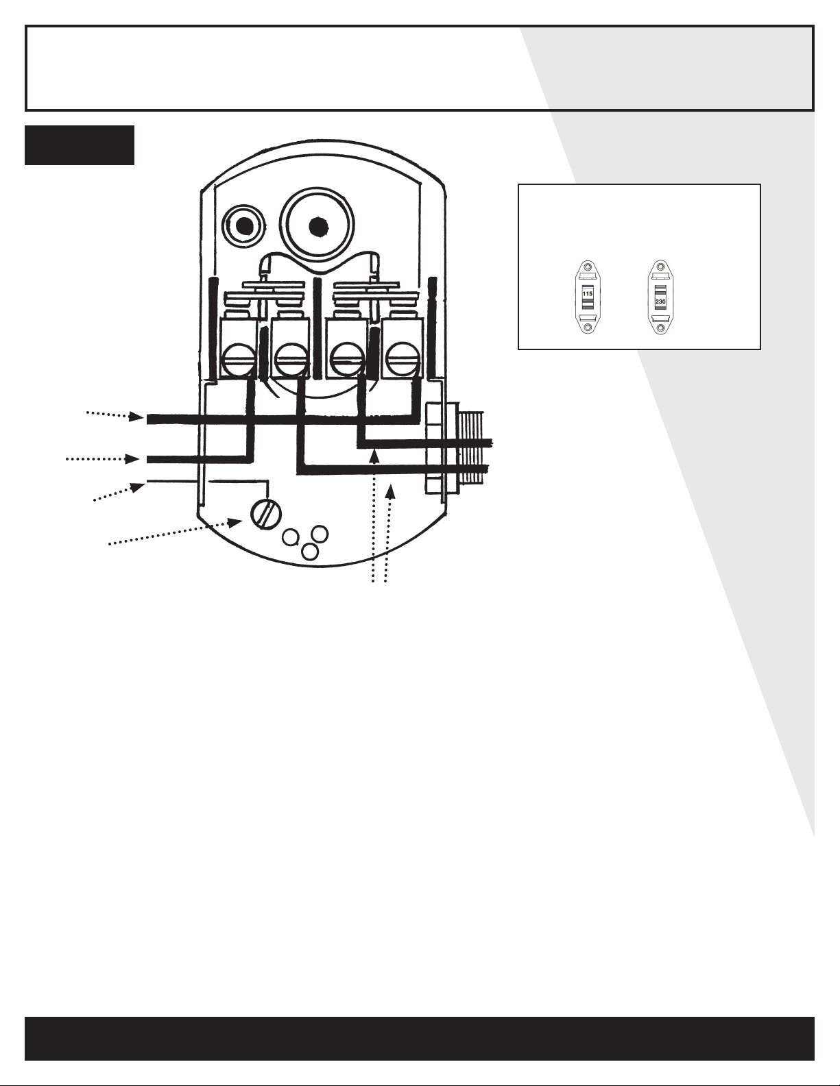
STEP 9
Electrical line
from home
distribution
panel.
BLACK
RED
ELECTRICAL INSTALLATION
1
2
VOLTAGE SELECTION SWITCH
1. POWER off.
2. Please SELECT the up knob position
for 115 V or down knob position for 230 V.
3. CONNECT to appropriate power source.
GREEN
GROUND
To motor lead
We recommend that a licensed electrician be employed to do the proper wiring to the pressure switch,
and to permanently ground the motor in accordance to the electrical codes in your area.
Do not use an extension cord to connect your pump to the power source. From your distribution panel to the
pressure switch, we recommend a wire gauge not smaller than 14 gauge.
This is a dual voltage 115/230 pump. The voltage selection switch is located inside the terminal box.
The motor is factory wired on 115V. For 230V selection, please open the terminal cover and set the switch to
the proper voltage. (See above drawing on right ).
Pressure switch setting (start/stop 20/40 or 30/50) has been made at the factory. Adjustments may be done
to give other operating pressures.
Adjustment or modication of start/stop setting of pressure switch have to be done carefully.
Turn adjustment nut half turn at a time.
Turn nut 1 clockwise to raise start and stop pressure setting. Never turn nut 2. This will change the 20 PSI
range between start and stop pressure and may damage your tank’s bladder or modify the efciency
of your water system. Check system operation after each adjustment.
7
FOR INFORMATION TEL: 514.337.4415 FAX: 514.337.4029
Page 8
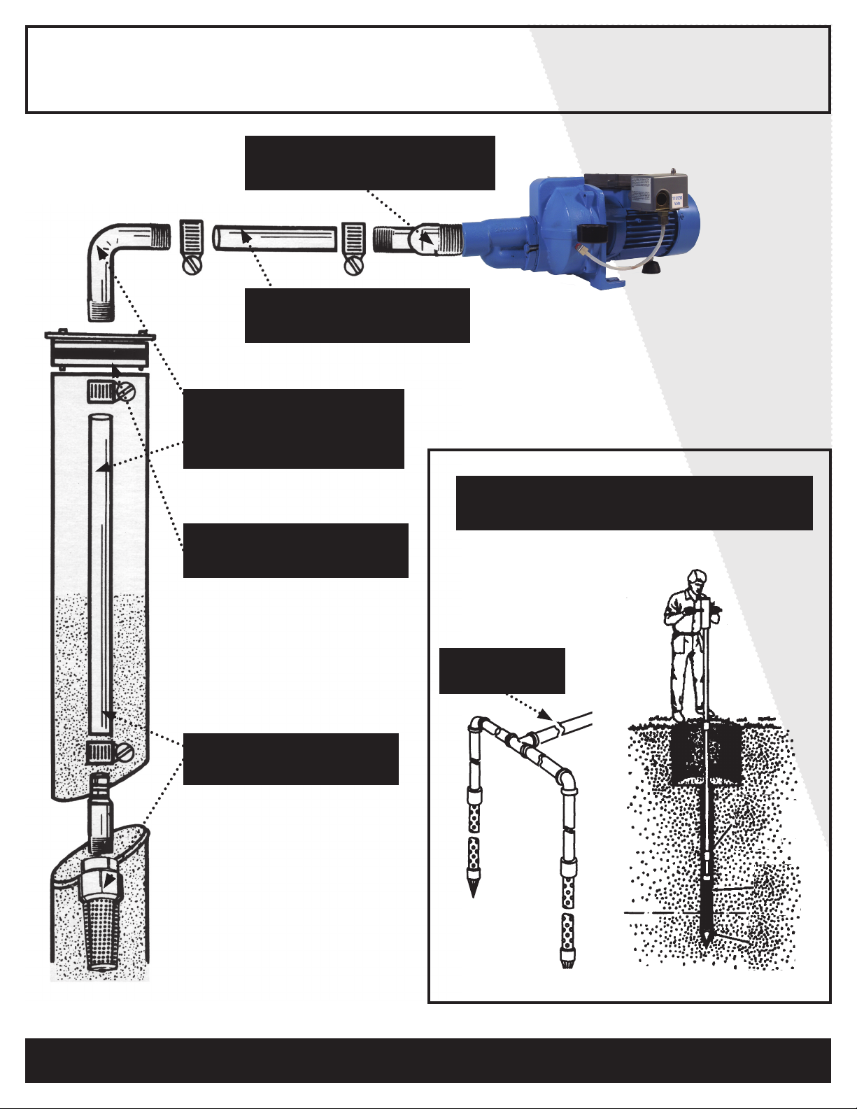
SHALLOW WELL APPLICATION
STEP 5 Install your pump
and thread an adaptor into inlet.
STEP 6 Cut poly
pipe and connect both ends.
STEP 3 Insert well
seal elbow through the seal
and attact to pipe.
STEP 4 Install well seal
and piping into well casing.
STEP 2 Cut poly pipe
and install the check valve.
Well point optional installation
STEP 7 You may install one or more sand
points to increase the supply of water.
Check valve,
close to pump.
8
FOR INFORMATION TEL: 514.337.4415 FAX: 514.337.4029
Page 9
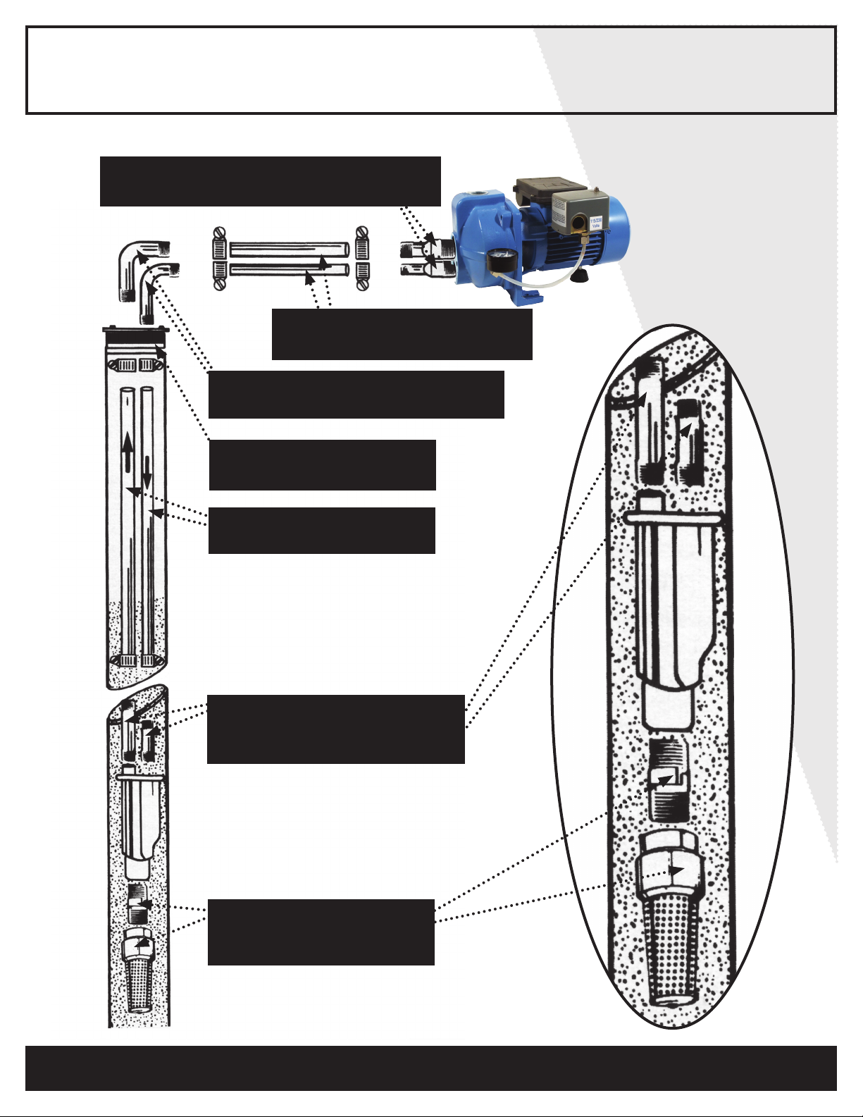
DEEP WELL APPLICATION
STEP 7 Install your pump and thread
adaptors into their respective opening.
STEP 8 Cut 1" and 1 ¼" poly
pipes and connect both ends.
STEP 5 Insert well seal elbows
thru the seal and attach to pipe.
STEP 6 Install well seal
and piping into well casing.
STEP 4 Cut 1" and 1¼"
poly pipes.
STEP 2 Screw 1¼" ven-
turi adaptor and 1" adaptor into
injector body.
STEP 3 Install 1" nipple
into 1" foot valve, then
screw in injector.
FOR INFORMATION TEL: 514.337.4415 FAX: 514.337.4029
9
Page 10
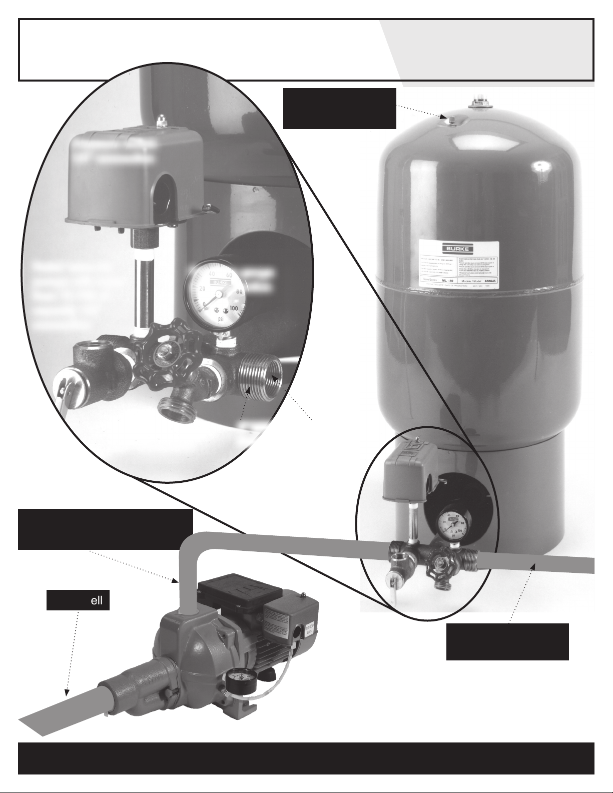
Pressure switch
1/4" connection
TANK INSTALLATION
Snifter valve to
adjust air pressure
Relief valve for
pumps with more
than 75 PSI of
capacity 1/2"
connection
Drain valve
1/2" connection
STEP 8 Connect the pump
discharge to the tank ' T '
Pressure gauge
1/4" connection
1" MNPT or 3/4"
FNPT connection
From well
To home’s plumbing
distribution line
10
FOR INFORMATION TEL: 514.337.4415 FAX: 514.337.4029
Page 11
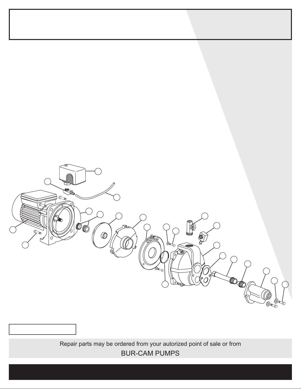
REPAIR PARTS
09
01
10
11
02
20
22
18
21
19
03
12
04
13
05
14
06
15
07
16
17
08
Ref Pieces Descriptions
1 510054 Motor 1/2HP
1 510054.1 Motor 3/4HP
2 510055 Motor Screws (4)
3 750957S Pressure Switch
4 510056 1/4" NPT 1/4" Barb Elbow
5 750748 Hose
6 510053 Seal Plate O-Ring
7 510052 Mechanical Seal
8 510048 Impeller
9 510047 Diffuser
10 510065 Diffuser Plate
11 510051 Diffuser Plate O-Ring
12 510050 Diffuser Plate Washers (3)
Ref Pieces Descriptions
13 510049 Diffuser Plate Screws (3)
14 510072 Flow Regulator
15 510056 1/4" NPT 1/4" Barb Elbow
16 510058 Pump Body
17 510061 Ejector Gasket
18.1 510066.1 Short Venturi
18.2 510066.2 Long Venturi (25'-60')
18.3 510066.3 Long Venturi (60’+)
19 510070 Nozzle
20 510062 Ejector Body
21 510063 Washers (2)
22 510064 Ejector Cap Screws (2)
23 750969 1/4" Pressure Gauge (not shown)
24 510077 Capacitor (not shown)
503321/503721 2011
Repair parts may be ordered from your autorized point of sale or from
BUR-CAM PUMPS
FOR INFORMATION TEL: 514.337.4415 FAX: 514.337.4029
11
Page 12
TROUBLE SHOOTING GUIDE CHECKLIST
NEVER MAKE ADJUSTMENTS TO ANY ELECTRICAL APPLIANCE OR PRODUCT WITH THE POWER
CONNECTED. DON’T JUST UNSCREW THE FUSE OR TRIP THE BREAKER, REMOVE THE POWER
FROM THE RECEPTACLE.
TROUBLE PROBABLE CAUSE ACTION
Motor does not
run.
Motor runs but
no water is
delivered.
Pump does not
deliver to full
capacity.
Pump does not
shut off.
Switch is off position
Blown fuse
Tripped breakerù
Dirty pressure switch
Defective pressure switch
Defective motor
Pump not primed
Leaky suction line
Foot valve plugged
Ejector nozzle clogged
Water level below foot valve
Suction lift to great
Improper voltage
Water level below foot valve
Ejector nozzle clogged
Excessive friction in pipe
Improper voltage
Leaky discharge line
Motor not up to normal speed
Improper setting of pressure switch
Ejector nozzle clogged
Turn switch to on position
Replace
Reset
Clean
Replace
Replace
Prime with clean water
Check pipe and pipe connections
Clean
Clean
Check foot valve level
Water level lower than lift capacity
Check voltage
Check foot valve level
Clean
Too small or dirty pipe
Check voltage
Check all pipes for leak
Check power cable and voltage
Reset or replace
Clean
Pump starts and
stop too often.
Air spurts from
fawcets.
12
Pressure tank waterlogged
Leaky foot valve
Leaky suction line
Foot valve do not close properly
Pressure switch out of adjustment
Leaky discharge line (toilet etc.)
Leaky suction line
Gaz in water
Airlogged tank (galvanized)
TO THE END CONSUMER
If you have any problems with the product, before advising the store, where
you’ve purchased the pump, please contact us at 514 337-4415 , and ask for
our sales department, and they will be pleased to help you with any questions
you might have, concerning your installation.
Drain tank and restart
Replace
Check pipe and pipe connections
Clean or replace
Adjust on/off setting
Check all pipes for leak
Check pipe and pipe connections
Check and consult factory
Replace air volume control
FOR INFORMATION TEL: 514.337.4415 FAX: 514.337.4029
 Loading...