


Life Pulse
High Frequency Ventilator
In-Service Manual
01513-07.12
|
Phone: |
801-467-0800 |
|
Hotline: |
800-800-4358 |
436 Lawndale Drive |
Fax: |
801-467-0867 |
Salt Lake City, UT 84115 |
Website: |
www.bunl.com |
01801-07.12 |
|
|

|
In-service Manual |
|
TABLE OF CONTENTS |
HOW TO USE THIS MANUAL ........................................................................................................................................... |
|
CHAPTER 1: OVERVIEW .................................................................................................................................................... |
|
HFV WITH CV ..................................................................................................................................................... |
3 |
LIFEPORT ADAPTER ....................................................................................................................................... |
4 |
CHAPTER 2: SETUP ............................................................................................................................................................ |
|
REAR PANEL CONNECTIONS ....................................................................................................................... |
6 |
FRONT PANEL CONNECTIONS .................................................................................................................... |
7 |
PATIENT BOX CONNECTIONS............................................................................................................... |
8 |
SETUP CAUTIONS ............................................................................................................................................ |
9 |
CHAPTER 3: VENTILATOR CONTROLS & TEST PROCEDURE ............................................................................... |
|
THE CONTROLS SECTION ............................................................................................................................ |
11 |
PERFORMING A TEST.................................................................................................................................... |
12 |
A FAILED TEST ................................................................................................................................................ |
13 |
CHAPTER 4: PRESSURE MONITORING......................................................................................................................... |
|
MONITOR DISPLAYS ...................................................................................................................................... |
15 |
PRESSING ENTER BUTTON ......................................................................................................................... |
16 |
PURGE PAUSES .............................................................................................................................................. |
17 |
CHAPTER 5: HUMIDIFIER .................................................................................................................................................. |
|
GAS FLOW THROUGH HUMIDIFIER ........................................................................................................... |
19 |
STARTING THE HUMIDIFIER ........................................................................................................................ |
21 |
CHANGING THE CIRCUIT .............................................................................................................................. |
22 |
CIRCUIT CHANGE PREPARATIONS ................................................................................................................. |
|
CHECKLIST ........................................................................................................................................................... |
|
FRONT PANEL DUTIES ....................................................................................................................................... |
|
PATIENT BOX DUTIES ........................................................................................................................................ |
|
POST-CIRCUIT CHANGE..................................................................................................................................... |
|
AFTER ENTER BUTTON IS PRESSED: .............................................................................................................. |
|
IMPORTANT.......................................................................................................................................................... |
|
TO COMPLETE A CIRCUIT CHANGE: .............................................................................................................. |
|
IDENTIFYING PROPER HUMIDIFICATION ................................................................................................. |
25 |
CHAPTER 6: START UP ..................................................................................................................................................... |
|
MEASURING & DISPLAYING PRESSURES............................................................................................... |
27 |
CHOOSING STARTING VALUES.................................................................................................................. |
28 |
6 STEPS TO START HFV................................................................................................................................ |
29 |
CHAPTER 7: PATIENT MANAGEMENT .......................................................................................................................... |
|
CLINICAL OBJECTIVES ................................................................................................................................... |
32 |
OXYGENATION................................................................................................................................................. |
33 |
OXYGENATION OVEREXPANDED LUNGS ................................................................................................. |
35 |
FINDING OPTIMAL PEEP ............................................................................................................................... |
36 |
VENTILATION ................................................................................................................................................... |
37 |
UNDERSTANDING SERVO PRESSURE ..................................................................................................... |
39 |
CHAPTER 8: SUCTIONING THE PATIENT ..................................................................................................................... |
|
SUCTION PROCEDURE #1 ........................................................................................................................... |
41 |
i

In-service Manual |
|
TABLE OF CONTENTS |
|
SUCTION PROCEDURE #2 ........................................................................................................................... |
42 |
READY LIGHT MUST BE ON!............................................................................................................... |
|
INSTILL INTO JET PORT THEN RECONNECT LIFE PULSE CIRCUIT. ............................... |
|
ONE PERSON DISCONNECT CV CIRCUIT FROM LIFEPORT. ................................................ |
|
SECOND PERSON APPLIES SUCTION GOING INTO AND OUT OF THE ET TUBE......... |
|
SUCTION PROCEDURE #3 ........................................................................................................................... |
44 |
SELECT AN IN-LINE SUCTION SYSTEM COMPATIBLE WITH THE LIFEPORT |
|
ADAPTER ............................................................................................................................................................. |
|
SELECT AN IN-LINE SUCTION SYSTEM WITH A CATHETER THAT IS STRAIGHT |
|
FOR THE FIRST FEW INCHES ..................................................................................................................... |
|
SUCTION ACCORDING TO PROCEDURE 1 OR 2 DESCRIBED EARLIER IN THIS |
|
SECTION .............................................................................................................................................................. |
|
CHAPTER 9: WEANING ...................................................................................................................................................... |
|
GENERAL GUIDELLINES FOR WEANING.................................................................................................... |
45 |
GENERAL GUIDELINES FOR WEANING .................................................................................................................... |
|
CHAPTER 10: VENTILATOR ALARMS........................................................................................................................... |
|
READY LIGHT ON............................................................................................................................................. |
48 |
ALARM LIMITS .................................................................................................................................................. |
49 |
JET VALVE FAULT ......................................................................................................................................... |
50 |
VENTILATOR FAULT: HFV CONTINUES RUNNING ................................................................................. |
51 |
VENTILATOR FAULT:HFV STOPS RUNNING.............................................................................................. |
52 |
VENTILATOR FAULT: CODE 10 ..................................................................................................................... |
53 |
LOW GAS PRESSURE .................................................................................................................................... |
54 |
CANNOT MEET PIP.......................................................................................................................................... |
55 |
LOSS OF PIP ..................................................................................................................................................... |
56 |
HIGH PIP............................................................................................................................................................. |
57 |
CHAPTER 11: INTERPRETING VENTILATOR ALARMS ............................................................................................ |
|
ALARM DISPLAY ......................................................................................................................................... |
58 |
LOOK AT THE PATIENT .................................................................................................................................. |
59 |
USE COMMON SENSE.................................................................................................................................... |
60 |
KNOW THE LIFE PULSE ................................................................................................................................. |
61 |
COMMON THINGS HAPPEN COMMONLY ................................................................................................. |
62 |
USE AVAILABLE RESOURCES ..................................................................................................................... |
63 |
CHAPTER 12: HUMIDIFIER ALARMS............................................................................................................................. |
|
HUMIDIFIER OPERATION .............................................................................................................................. |
65 |
CIRCUIT FAULT: LEVEL ALARM................................................................................................................... |
66 |
WATER LEVEL SENSING ............................................................................................................................... |
67 |
CIRCUIT TEMPERATURE............................................................................................................................... |
68 |
TEMPERATURE CONTROLS......................................................................................................................... |
69 |
SETTING CARTRIDGE TEMPERATURE ..................................................................................................... |
70 |
CONDENSATION PROBLEMS....................................................................................................................... |
71 |
MANUALLY PURGING ..................................................................................................................................... |
72 |
HIGH / LOW WATER LEVEL........................................................................................................................... |
73 |
HIGH / LOW TEMPERATURE......................................................................................................................... |
74 |
APPENDIX A: POST-TEST QUESTIONS......................................................................................................................... |
|
APPENDIX B: POST-TEST ANSWERS ............................................................................................................................ |
|
ii
Each chapter begins with a chapter designation
Each page will list its contents large, bold, capitol letters
Introduction
HOW TO USE THIS MANUAL
Objectives
1.Understand how to use this manual.
2.Know how to navigate to the information you need.
Each chapter includes objectives for the reader
ENTER SILENCE
CONTROLS
ENTER STANDBY ENTER
ON
STANDBY
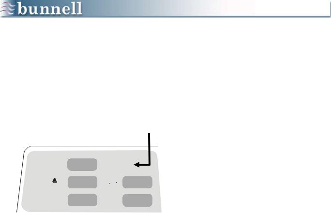
Graphics and instruction boxes will appear in the
INSTRUCTION BOXES
Boxes containing instructions and summaries of procedures will appear in lightly shaded boxes and will look like this.
WARNING: Warnings will also appear in lightly shaded boxes and will look like this.
Text that lists sequential procedures:
1.Is numbered
2.Like this
Otherwise, lists will be:
Bulleted
Like this
Text that instructs you to press a button will highlight the button‟s font like this: press MENU
Text will appear in the right column
1
Chapter 1
OVERVIEW
Objectives
1.Know the 5 subsystems of the Life Pulse and their purposes.
2.Understand the relationship between the Life Pulse and the conventional ventilator.
3.Know the structure and function of the LifePort adapter.
The Life Pulse High-Frequency Ventilator is a microprocessor-controlled infant ventilator capable of delivering and monitoring between 240 and 660 heated, humidified breaths per minute.
MONITOR ALARMS CONTROLS
PATIENT BOX |
|
HUMIDIFIER |
||
|
|
|
|
|
INDICATOR LED |
|
MODEL 203 |
MODEL 203A |
|
|
|
|
|
|
STANDBY |
|
Red |
Yellow |
|
|
|
|
|
|
TEST |
|
Red |
Yellow |
|
|
|
|
|
|
JET VALVE OFF |
|
Red |
Yellow |
|
|
|
|
|
|
READY |
|
Red |
Green |
|
|
|
|
|
|
WAIT |
|
Red |
Yellow |
|
|
|
|
|
|
CIRCUIT |
|
Red |
Yellow |
|
|
|
|
|
|
CARTRIDGE |
|
Red |
Yellow |
|
|
|
|
|
|
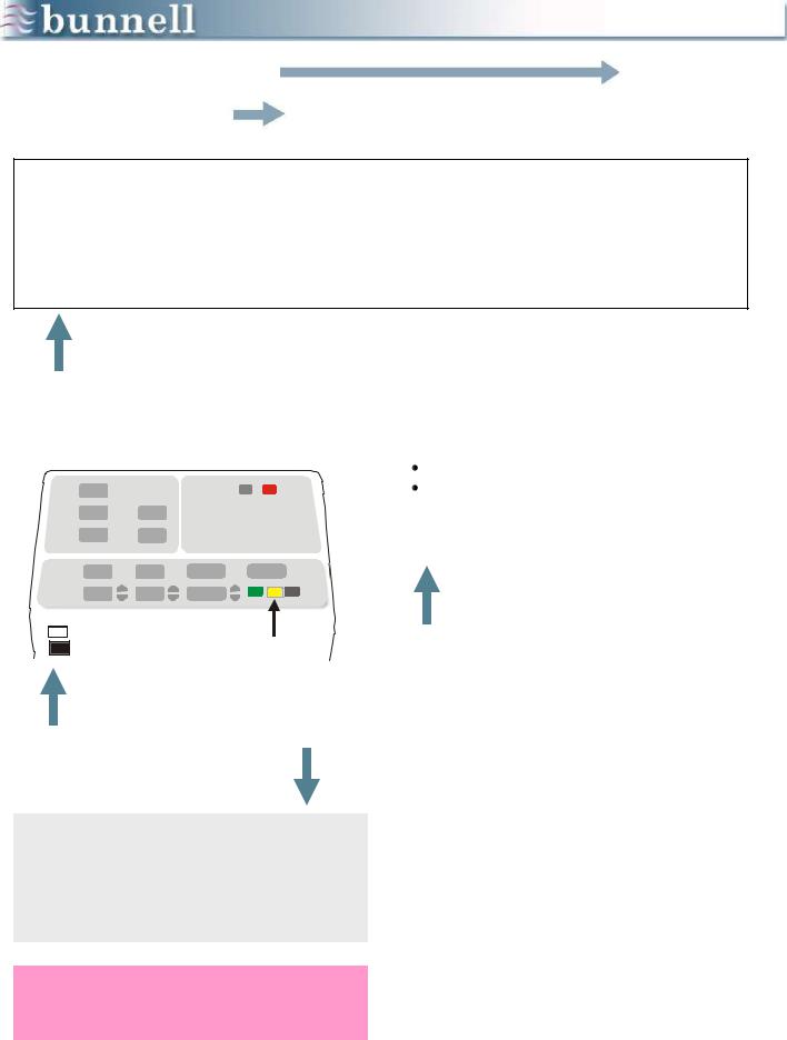
The Life Pulse is composed if 5 subsystems:
MONITOR: Displays patient and machine pressures.
ALARMS: Indicates various conditions that may require attention.
CONTROLS: Regulates the On-Time, Peak Inspiratory Pressure, and Rate of the HFV breaths.
HUMIDIFIER: Monitors and controls the temperature and humidification of gas flowing through the disposable humidifier circuit to the patient.
PATIENT BOX: Contains the pinch valve that breaks the flow of pressurized gas into tiny jet pulses and sends pressure information back to the ventilator‟s microprocessor.
Together, these elements form a system that offers a variety of options for managing patients and the potential for improving blood gases using less pressure.
NOTE: Graphics that display illuminated indicator lamps (LEDs) in this manual reflect Life Pulse model 203. For model 203A, please refer to the table at right:
2
VENTILATOR FUNCTIONS
LIFE PULSE
High-frequency breaths
Airway pressure monitoring
Humidification Alarms
CONVENTIONAL VENTILATOR
Regulate PEEP
Fresh gas for spontaneous breathing
Supplementary IMV Airway dilation
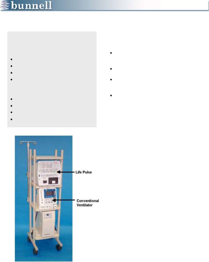
HFV with CV
The Life Pulse is used in conjunction with a conventional infant ventilator. The conventional ventilator has 4 functions:
provides fresh gas for the patient‟s spontaneous breathing,
regulates PEEP,
provides supplementary IMV when needed, and
provides periodic dilation of airways when needed.
The purpose of the supplementary IMV is to provide background breaths sufficient to recruit atelectatic alveoli.
The purpose of the PEEP provided by the conventional ventilator is to maintain the inflation of alveoli with adequate FRC.
Using IMV periodically to dilate airways without interrupting the Life Pulse affords opportunities to ventilate areas downstream from airway restrictions.
3
|
15 mm port |
|
Pressure |
Jet |
|
monitoring |
||
port |
||
port |
||
|
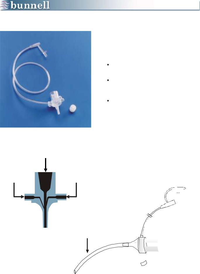
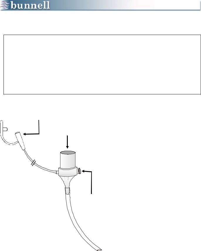
LifePort Adapter
The LifePort adapter allows both the conventional ventilator and the Life Pulse to be connected to a patient. The LifePort has three main features:
15 mm Port: provides the standard connection to the conventional ventilator.
Jet Port: the entrance for the highfrequency pulses provided by the Life Pulse.
Pressure Monitoring Tube: allows the Life Pulse to display approximations of distal tip airway pressures.
Accurate pressure measurements through the LifePort are fed back to the ventilator and provide the Life Pulse with information necessary to control peak inspiratory pressure (PIP) .
For example, if the measured PIP is higher than the set PIP, the Life Pulse stops pulsing. If the PIP suddenly reaches automatically set criteria, the Life Pulse dumps the stored Servo Pressure to insure that the Life Pulse will not deliver excess gas to the patient.
Pressure monitoring tube 
Conventional endotracheal tube


 Main port Jet inlet port


Jet port cap 

4
Chapter 2
SETUP
Objectives
1.Understand the connections to the electrical power, air, oxygen, and water necessary for the Life Pulse to function.
2.Know how to install the humidifier cartridge and circuit.
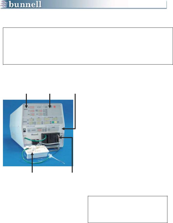
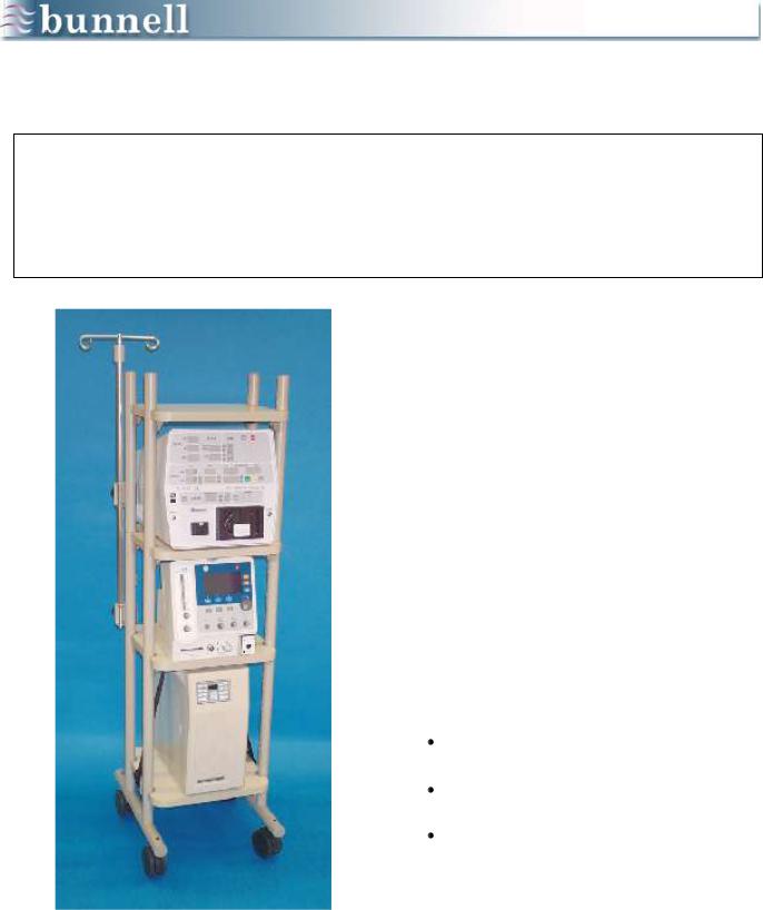
The Life Pulse should be positioned so that the displays are easy to read and its controls and the conventional ventilator controls are within easy reach. The cart is on 5 inch, lockable casters for easy portability and stability.
The Bunnell ventilator cart is designed to carry most of the patient‟s cardiopulmonary equipment. For example, oxygen analyzers and other monitors can be placed on the top shelf.
The Life Pulse is typically placed on the second shelf, the conventional ventilator on the third, and an uninterruptable power supply on the bottom.
Setup procedures for the Life Pulse include making connections in three places:
the Rear Panel,
the Front Panel, and
the Patient Box.
5
|
|
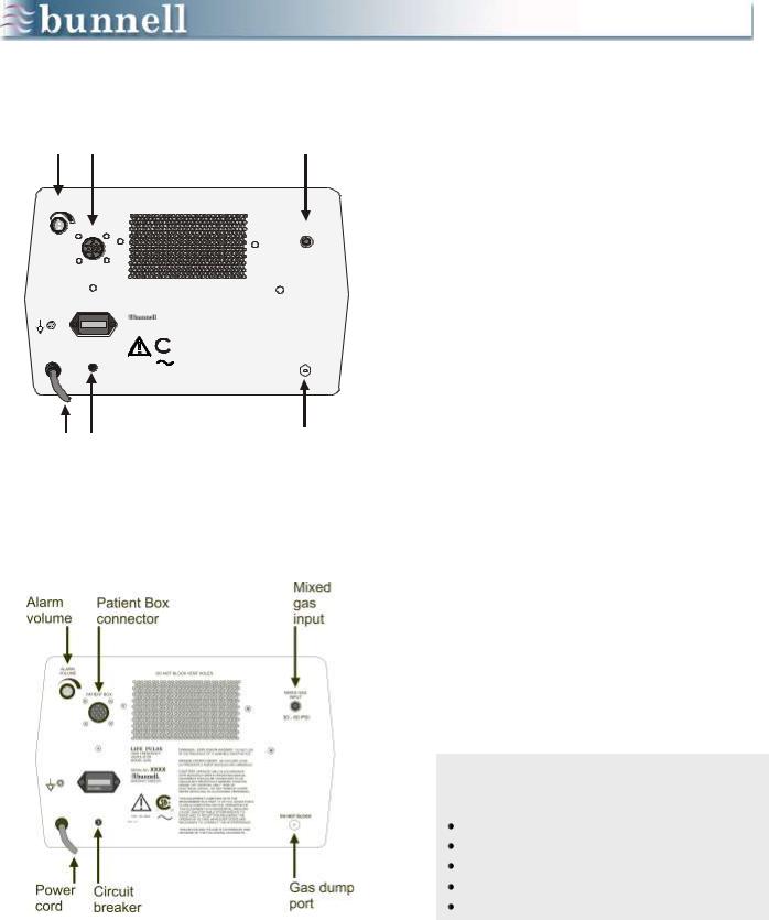
Mixed |
Alarm |
Patient Box |
gas |
volume |
connector |
input |
ALARM
VOLUME
Power cord
DO NOT BLOCK VENT HOLES
PATIENT BOX
++
++
+
HOURS
3
+
LIFE PULSE
HIGH FREQUENCY
VENTILATOR
MODEL 203A
SERIAL NO. XXXX
MADE IN THE U.S.A.
MANUFACTURED BY

 ®
®
C US
120V / 3A / 60Hz
02641– 00.3
+
DANGER-- EXPLOSION HAZARD: DO NOT USE IN THE PRESENCE OF FLAMMABLE ANESTHETICS.
RISQUE D’EXPLOSION: NE PAS EMPLOYER
EN PRESENCE D’ANESTHESIQUES INFLAMMABLES
CAUTION: OPERATE ONLY IN ACCORDANCE
WITH MANUFACTURER’S OPERATING MANUAL.
EQUIPMENT SHOULD BE CONNECTED TO AN
EQUIVALENT RECEPTACLE MARKED “HOSPITAL GRADE” OR “HOSPITAL ONLY”. RISK OF
ELECTRICAL SHOCK: DO NOT REMOVE COVER. REFER SERVICING TO AUTHORIZED PERSONNEL.
.
THIS EQUIPMENT COMPLIES WITH THE REQUIREMENTS IN PART 15 OF FCC RULES FOR A CLASS A COMPUTING DEVICE. OPERATION OF THIS EQUIPMENT IN A RESIDENTIAL AREA MAY CAUSE UNACCEPTABLE INTERFERENCE TO RADIO AND TV RECEPTION REQUIRING THE OPERATOR TO TAKE WHATEVER STEPS ARE NECESSARY TO CORRECT THE INTERFERENCE.
THIS DEVICE AND ITS USE IS COVERED BY ONE OR MORE OF THE FOLLOWING US PATENTS.
Circuit breaker
MIXED GAS
INPUT
30 - 60 PSI
+
DO NOT BLOCK
Gas dump port
Life Pulse Model 203
Life Pulse Model 203 A
REAR PANEL
CONNECTIONS
1.Plug in the power cord to a standard 110 volt outlet or, preferably, an uninterruptible power supply.
2.Connect a high-pressure oxygen hose from a low flow air/oxygen blender (0-30 L/min) or the output from the low flow port (2-100 L/min) of a standard blender to the Mixed Gas Input fitting. A minimum pressure of 30 psi is required to operate the Life Pulse.
3.Attach an oxygen analyzer to the Oxygen Sensor in order to monitor FiO2 (not applicable to serial number 2414 or higher), or monitor FiO2 from the air/oxygen blender output.
4.With Model 203, plug in one of a variety of recording devices to the Analog Output to monitor airway pressure graphically (Optional).
5.Connect the Patient Box to the ventilator by its electrical cable attached to the multipinned connector.
6.Adjust the volume of the audible alarms using the Alarm Volume dial.
CHECKLIST
Rear Panel Connections
Power cord
Gas in from blender
O2 Sensor (Only SN‟s 2413 and lower)
Patient Box Alarm volume
6
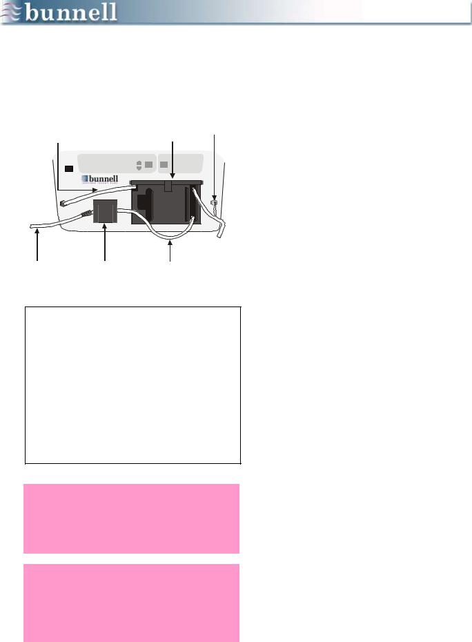
FRONT PANEL CONNECTIONS
2 |
1 |
3 |
||||
Green gas inlet |
Cartridge |
Purge tube |
||||
tube to Gas Out |
in door |
|
||||
|
|
|
|
|
|
|
|
|
|
|
|
|
|
|
|
|
|
|
|
|
|
|
|
|
|
|
|
GAS OUT |
PURGE |
|
Transfer tube to |
Water |
Water inlet |
water supply |
Pump |
tube |
6 |
5 |
4 |
CHECKLIST
Front Panel Connections
1Cartridge in and door latched
2Green gas inlet tube
3Purge tube
4Water inlet tube
5Water pump
6Water supply bag
WARNING: The water supply should be positioned at or below the level of the humidifier cartridge to decrease the potential of overfilling the cartridge by gravity feed.
WARNING: The water inlet tube of the humidifier cartridge/circuit must be latched into the pump housing to prevent cartridge overfill and delivery of water to the patient by gravity feed.
1.Insert the Humidifier Cartridge into the cartridge door. Latch the door shut to make all electrical connections between the cartridge and the Life Pulse.
2.Connect the green gas inlet tube to the large barbed connector labeled GAS OUT.
3.Connect the small diameter purge tube to the barbed connector labeled PURGE.
4.Locate the water inlet tube, a clear tube running from the lower right corner of the cartridge with a check valve and a Leur fitting on the end.
5.Install the water inlet tube by placing the clear tube into the pump housing, closing the pump door securely to pinch the water inlet tube inside, and connect the water transfer tube to the Luer connector on the end of the water inlet tube.
6.Tap the sterile water bag with the other end of the water transfer tube and open the tubing clamp.
Use only sterile water for the cartridge water supply.
7
PATIENT BOX CONNECTIONS
Purge |
Push To Load |
|
To |
|||
Tube |
button |
|
Patient |
|||
|
|
|
|
|
|
|
|
|
|
|
|
|
|
|
|
|
|
|
|
|
|
|
|
|
|
|
|
Pinch
Tube
Pinch
Valve
End view
CHECKLIST
Patient Box Connections
Pinch tubing in pinch valve
Purge tube connect
1.Locate the soft pinch tubing portion of the circuit just beyond where the red and white wires inside the circuit terminate.
2.Place the pinch tubing in line with the pinch valve assembly.
3.Hold the pinch tubing on each side of the pinch valve assembly.
4.Press the PUSH TO LOAD button with one finger.
5.Slide the pinch tubing into the pinch valve assembly until you feel it snap into place.
The illustrations on the left show a proper pinch tubing placement. The entire width of the pinch tube should be within the pinch valve jaws.
6.Connect the small purge tube to the barbed connector labeled FROM PURGE.
The disposable humidifier cartridge and circuit are now ready for operation, and the Life Pulse is ready to be turned on.
8

SETUP CAUTIONS
Two cautions should be noted about the Set Up procedure:
First, patients are often placed on the Life Pulse on an emergency basis. You can save time if the ventilator is stored clean and partially set up, ready for use.
Do NOT install the pinch tube in the pinch valve prior to actual patient set-up.
The disposable cartridge/circuit, water transfer tube, and a test lung can be placed with the Life Pulse. If using the Bunnell Cart, everything necessary to begin high-frequency jet ventilation can be wheeled to the patient‟s bedside.
Second, notice that the installation description includes only cartridge/circuit tubing supplied by Bunnell Incorporated.
Do NOT make modifications to the supplies or the set up procedure!
Pressures cannot be monitored accurately and the Life Pulse will not work properly if other equipment is teed into the pressure monitoring tube or if leaks are present in the circuit.
9
Chapter 3
VENTILATOR CONTROLS &
TEST PROCEDURE
Objectives
1.Be able to attach the Life Pulse circuit to the LifePort adapter.
2.Understand the ON, STANDBY, ALARM SILENCE, TEST, and ENTER buttons.
3.Know how to perform a Life Pulse systems test and know the meaning of VENTILATOR FAULT alarms 02, 03, and 04.
4.Be able to enter NEW settings and convert them to NOW settings.
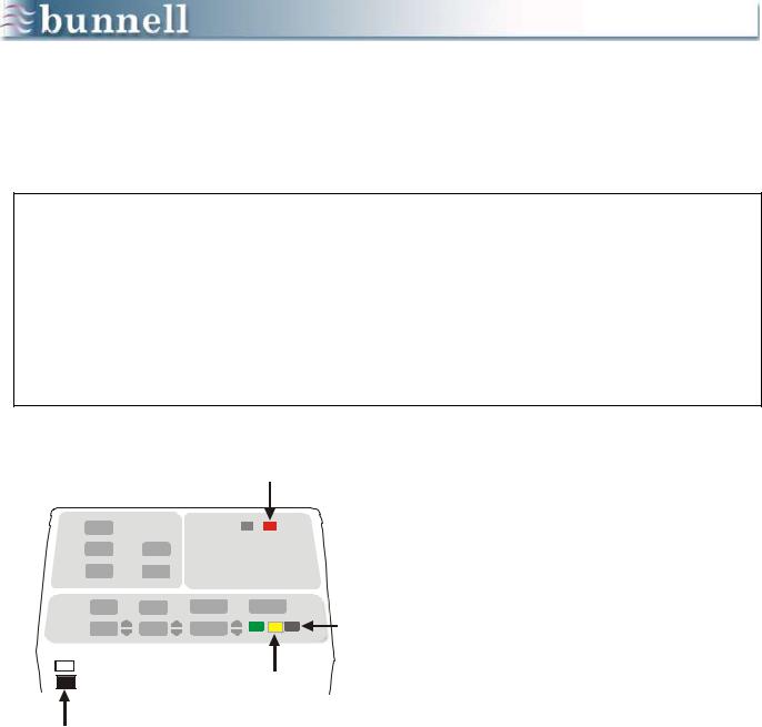
CONTROLS
ON
POWER ON
SILENCE
ENTER SILENCE
ENTER STANDBY ENTER |
TEST |
STANDBY
This section discusses how to manipulate the CONTROLS and perform a systems test.
When the ON button is pressed, the Life Pulse activates into the Standby mode with an audible alarm sounding.
The Standby mode is indicated by a small light in the corner of the STANDBY button and an audible alarm every 30 seconds. The alarm may be silenced by pushing the SILENCE button.
Once the 60-second alarm silence time has expired, the audible alarm will sound 6 beeps every 30 seconds to remind you that the Life Pulse is in the Standby mode and not operating.
The Life Pulse can monitor conventional ventilator and other high-frequency ventilator pressures in the Standby mode.
This information will be displayed in the MONITOR section.
10
THE CONTROLS SECTION
PIP |
RATE |
on JET VALVE TIME on/off |
NOW
CONTROLS
NEW
ENTER |
STANDBY |
TEST |
+
+
+
+
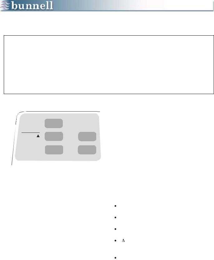
There are only three setting parameters in the CONTROLS section: PIP (Peak Inspiratory Pressure), RATE, and JET VALVE ON Time, which is nearly synonymous with Inspiratory Time.
These settings may be changed by pressing the up and down arrow buttons next to their respective displays.
1.Press the ENTER button to transfer the NEW settings into the NOW settings (the settings the patient will receive).
2.Press the STANDBY button to place the Life Pulse into the Standby mode. The Life Pulse stops producing high-frequency jet ventilation and only the NEW settings are displayed.
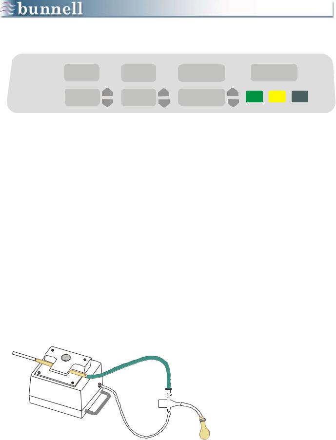
A systems test should be performed to insure that the Life Pulse is in good operating condition before connecting the system to a patient.
A test lung must be attached to the patient end of a standard endotracheal tube and LifePort adapter prior to performing the Test.
The test lung can be as simple as the one pictured: a finger cot, or the finger of a rubber glove, taped lightly to the tip of the ET tube.
11
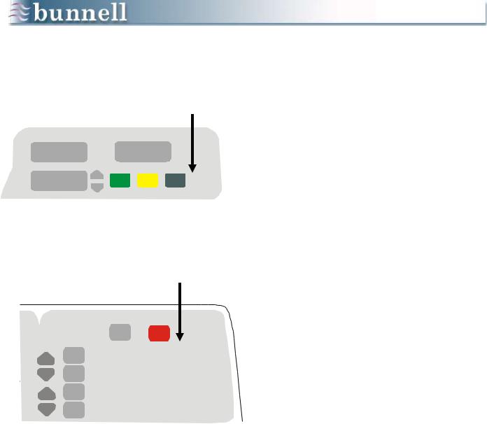
Press TEST button to begin systems test.
on |
JET VALVE TIME on/off |
seconds
ENTER STANDBY TEST
All possible alarms will be illuminated briefly during the systems test.
ALARMS |
RESET |
SILENCE |
JET VALVE FAULT
VENTILATOR FAULT
LOW GAS PRESS
CANNOT MEET PIP
LOSS OF PIP
HIGH PIP
PERFORMING A TEST
The Life Pulse‟s systems test will ensure that the ventilator is operating according to specifications. To perform the test, follow these steps:
1.Attach a LifePort adapter to an ET tube and test lung.
2.In the Standby mode, connect the patient end of the Life Pulse circuit, coming from the pinch valve, to the Jet port on the side of the LifePort adapter.
3.Connect the clear pressure monitoring tube of the LifePort adapter to the Patient Box barbed connector labeled MONITORING LUMEN.
4.Press the TEST button. An automatic test begins which determines the integrity of all the ventilator‟s electronics and valves.
5.Observe the front panel to assure all LEDs and displays are functional, and listen to make sure the audible alarm is functioning properly. If no problems are detected, all the ventilator displays will illuminate 1 through 9 in sequence and all the alarm messages will be displayed.
The Test procedure will end with the Life Pulse in the Standby mode and an audible alarm sounding.
6.Silence the audible alarm by pressing the SILENCE button. The audible alarm stops for 60 seconds.
7.Once the internal Test passes, perform an operational test using the test lung. A conventional ventilator is not needed and the LifePort adapter 15mm connector is left open to the room.
8.Press the ENTER button to activate the default control settings (20, 420, 0.02).
9.Once the PIP is stable, the Ready light will activate. Make sure the pressures are stable and the PEEP is reading 0.0 ± 1 cm H2O.
10.If the PEEP is > ± 1 cm H2O, switch out the Patient Box and repeat the operational test.
12
ENTER SILENCE
VENTILATOR FAULT
on |
JET VALVE TIME |
on/off |
|
seconds |
|
|
ENTER |
STANDBY TEST |
CHECKLIST
Fault Code Numbers
02Purge tube disconnect or pressure transducer failure
03Green gas inlet tube disconnect, pinch tube incorrectly installed, or stuck Servo Pressure control valve
04 Electrical component failure
WARNING: All patient connections to the Life Pulse circuit must only be made while the Life Pulse is in the STANDBY mode. Failure to comply may result in a high volume of gas being delivered to the patient.
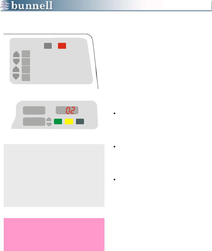
A FAILED TEST
If an internal fault is detected, the test sequence will stop, VENTILATOR FAULT will be displayed in the ALARMS area, and a code number 02, 03, or 04 will appear in the ON/OFF window of the CONTROLS section.
A VENTILATOR FAULT code may or may not mean the Life Pulse has a serious problem.
For example, if the purge tube is disconnected during the Test, either at the Patient Box or the front panel, a VENTILATOR FAULT 02 will be displayed.
VENTILATOR FAULT 02 - check the purge tube for a disconnect at the front panel or the Patient Box. This fault will also occur if the pressure transducer in the Patient Box has failed.
VENTILATOR FAULT 03 - check the green gas inlet tube for a disconnect at the GAS OUT connector. This fault may also occur if one of the Servo Pressure control valves is not working properly.
VENTILATOR FAULT 04 - You may observe the Life Pulse performing this check by watching the code display area closely. As the test is performed, the display momentarily flashes 04. If the test is passed, the 04 disappears. If it fails, the
04 stays lit, a VENTILATOR FAULT code appears, and an audible alarm sounds.
Once it has successfully passed the test, and after operating properly on a test lung, the Life Pulse is ready for clinical use.
If the Life Pulse is unable to achieve the desired settings on a test lung, or the cause of a VENTILATOR FAULT cannot be determined, or an 04 stays displayed at the end of the test, call the Bunnell Hotline (1-800-800-4358).
13
Chapter 4
PRESSURE MONITORING
Objectives
1.Appreciate the advantages of the LifePort Adapter and the purpose of each of its 3 ports.
2.Understand the parameters displayed in the MONITOR section and where they are measured.
3.Understand Servo Pressure and its clinical relevance.
4.Understand the function of the PURGE.
PIP |
JET VALVE |
|
|
cm H2O |
ON OFF |
MONITOR
P |
SERVO |
|
PRESS |
||
cm H O |
||
|
PSI (0.145kPa) |
|
PEEP |
MAP |
|
cm H2O |
cm H2O |
The MONITOR displays reflect the pressures at the tip of the endotracheal tube and the internal Servo or drive pressure of the Life Pulse. If the Life Pulse is in Standby, and there is no patient connected to the Patient Box, the displays will all read zero.
Once the pressure monitoring tube of the LifePort adapter has been connected to the Patient Box, the Life Pulse, even in its Standby mode, will begin to monitor the pressures being delivered by the conventional ventilator. These pressures are updated in the MONITOR displays every 10 seconds.
The Life Pulse monitors:
PIP: Peak Inspiratory Pressure,
PEEP: Positive End-Expiratory Pressure,
MAP: Mean Airway Pressure,
P: PIP minus PEEP, roughly equivalent to tidal volume, and
SERVO PRESSURE: internal driving pressure; always 0.0 in Standby mode.
14

PIP
PEEP
MAP
P (i.e., VT)
SERVO PRESSURE
SERVO PRESSURE
Improved compliance and/or resistance Air leak
Disconnected tube
SERVO PRESSURE
Worsening compliance and/or resistance ET tube obstruction
Tension pneumothorax Patient needs suctioning Right mainstem intubation
MONITOR DISPLAYS
PIP: the average of maximum airway pressures measured during a set time period
PEEP: the average minimum airway pressure
MAP: is an average of pressures measured from the total pressure waveform. It includes pressures produced by highfrequency ventilation, conventional ventilation, or spontaneous breathing.
P: (Delta P) simply the arithmetic difference between PIP and PEEP. P is roughly proportional to Tidal Volume and its importance in clinical decision making will become more apparent in the discussion of patient management.
SERVO PRESSURE: the internal drive pressure of the Life Pulse; indicates how much gas flow must be produced to meet the NOW PIP, Rate, and On-Time requested by the operator.
Servo Pressure is regulated by the ventilator‟s microprocessor and is outside the control of the operator. Bigger patients, or those with more compliant lungs, will require higher Servo Pressures whereas those infants with smaller and/or less compliant lungs will require lower Servo Pressures.
Servo Pressure is an indication of how much gas flow the Life Pulse must generate to meet the settings requested. Servo Pressure changes above or below the established operating level for a particular patient may be a result of changes in lung compliance, airway resistance, or lung volume.
Servo Pressure changes give an early indication that the patient‟s condition may be improving or worsening.
15

PRESSING ENTER BUTTON
on |
JET VALVE TIME on off |
Press ENTER button to begin ventilation
READY light ON
ALARMS RESET READY SILENCE
Jet Valve ON/OFF lights flash
PIP |
JET VALVE |
|
ON OFF |
||
cm H20 |
||
MONITOR |
SERVO |
|
P |
||
PRESS |
||
cm H20 |
||
|
PSI (0.145kPa) |
When the ENTER button is pressed, the microprocessor will begin increasing the Servo Pressure from zero to whatever value will produce the NOW PIP at the end of the
NOW ON-TIME at the NOW RATE.
Although it will typically take a short time for the actual PIP to reach the NOW PIP, the displayed PIP will equilibrate slower because of the averaging characteristics of the display. Thus, it may take longer (typically within a minute) for the monitored PIP to reach the NOW PIP.
When the monitored NOW PIP is stable for 20 seconds, the READY light will illuminate. The READY light indicates the Life Pulse is providing ventilation at the settings you have requested, and alarm conditions that are set automatically have been established.
(The specific criteria which produce the READY condition are discussed in the ALARMS section, but the READY condition is mentioned here because the monitoring specifications change after the READY light is on: the display is updated every 2 seconds.)
The JET VALVE ON/OFF lights turn on and off in conjunction with the pinch valve that is located in the Patient Box. ON means the valve is open. OFF means the valve is closed.
These lights serve as a visual check on the status of high-frequency ventilation in general and on the extent to which the patient or the conventional ventilator may be causing interruptions of the Jet pulses.
PEEP |
MAP |
cm H20 |
cm H20 |
The Life Pulse will sense a high pressure and will pause whenever the monitored PIP exceeds the NOW PIP. Ventilation resumes when the PIP drops below the set level. Monitor such interruptions visually by watching the ON/OFF lights.
16
Extended pauses of the Green Jet Valve ON light indicate an interruption of jet pulses
PIP |
JET VALVE |
|
ON |
||
cm H20 |
||
MONITOR |
SERVO |
|
P |
||
PRESS |
||
cm H20 |
||
|
PSI (0.145kPa) |
|
PEEP |
MAP |
|
cm H20 |
cm H20 |
PURGE PAUSES
The Life Pulse may pause periodically and briefly during operation for no apparent reason. Such pauses can occur during clinical use or when you are operating on a test lung.
These brief pauses are usually a result of the purge of the pressure monitoring tube that takes place once every 15 seconds.
The Purge valve is located next to the pressure transducer inside the Patient Box. When the valve opens it allows a pulse of dry air to flush the pressure monitoring tube.
On rare occasions, the purge may cause high pressure to be measured by the transducer that, in turn, makes the Life Pulse skip a beat in conjunction with its built-in response to high pressures.
Do not be concerned if the Life Pulse appears to hiccup every once in a while. If you time the pauses, you will find that they occur at some multiple of 15 seconds. (This pause usually will only occur on rates of 550 bpm or greater.)
17
Chapter 5
HUMIDIFIER
Objectives
1.Describe the flow of gas from the ventilator through the entire length of the Humidifier Cartridge/Circuit.
2.Understand the purpose of humidification and how it is produced and regulated.
3.Learn to adjust the temperature manually in the cartridge and the circuit.
4.Understand the function of the pinch tube portion of the circuit.
Gas inlet |
Cartridge |
tube |
thermistor |
 Purge tube
Cartridge |
|
Water supply tube |
Circuit |
|
Circuit thermistor
Heating Wire
Purge tube
 Pinch Tube
Gas to patient
The Life Pulse humidifier uses a one-piece disposable cartridge and tubing set called the humidifier cartridge/circuit. This item is often referred to as “the cartridge”, “the circuit”, or “the patient breathing circuit”.
All are terms that refer to all or part of the humidifier cartridge/circuit. It is preassembled and contains the heating wire, thermistors, and all connections needed for operation.
Gas from the GAS OUT connector on the front panel of the ventilator flows into the humidifier cartridge via the green gas inlet tube.
The shorter clear tube is the water inlet tube and contains a check valve that prevents gas from leaking out when the water supply bag is disconnected.
Water is pumped into the cartridge against the cartridge pressure. Once the water inlet tubing is securely closed in the pump housing, water and air cannot be forced back into the water supply bag.
18
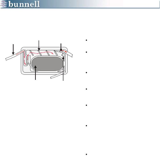
GAS FLOW THROUGH HUMIDIFIER
Gas inlet |
Baffles |
Temperature |
|
tubing (Green) |
|
thermistor |
|
|
|
|
|
To Patient
Heating |
Water level |
plate |
sensing pins |
The gas flows from the Life Pulse to the patient as follows:
The gas enters the cartridge through the green gas inlet tube.
The gas flows down below the water level then back up through a venturi mechanism, which atomizes some of the heated water.
The gas then flows over the heated reservoir of water and past a series of baffles which knock out water droplets.
The humidified gas passes over the cartridge thermistor which measures the temperature.
The microprocessor uses this temperature to regulate the amount of heat delivered to the cartridge through the metal heating plate.
This feedback control system uses the CARTRIDGE temperature setting on the humidifier front panel as its set point and controls the humidification of gas being delivered to the patient, not the temperature.
Heated and humidified gas leaves the cartridge and enters the circuit tubing with the red and white wires inside.
The temperature thermistor at the tip of the white circuit wire measures the actual temperature of the humidified gas in the circuit just before the Patient Box. The value is displayed as CIRCUIT TEMP in the humidifier display section.
The red wire is a heating element that is turned on and off according to feedback from the circuit temperature.
19
GAS FLOW THROUGH HUMIDIFIER
(cont.)
Pinch
Tube
Pinch
Valve
Using the CIRCUIT temperature setting on the humidifier front panel as its set point, the microprocessor controls the temperature of the gas being delivered to the patient.
The heating wire also minimizes the amount of condensation in the tubing to control
“rainout.”
The heated and humidified gas flows into the pinch tube section of the circuit where the pinch valve breaks the flow into breaths.
The gas begins to cool as it leaves the pinch valve and condensation occurs as a result of the cooling.
The temperature of the gas that enters the LifePort adapter will be approximately 3o C less than when it was last measured by the circuit thermistor.
Therefore, the CIRCUIT temperature is automatically set at 40o C on the front panel by the microprocessor.
The intention is to deliver the gas to the patient at close to 37o C, normal body temperature.
20
STARTING THE HUMIDIFIER
Press ENTER button to initially start humidifier
Press WAIT button to stop and start humidification
|
ENTER |
|
WAIT |
|
HUMIDIFIER |
GAS OUT |
PURGE |
|
The Life Pulse Humidifier requires little operator intervention. The temperature of the gas is regulated by feedback control from the point where it enters the cartridge to the point where it enters the Patient Box.
When the Life Pulse is first turned on, the ventilator comes up in its Standby mode and the humidifier is in its WAIT mode. The two modes are equivalent; there is no ventilation and no humidification or heating being done in these modes.
When the ENTER button is pressed, the light in the corner of the WAIT button goes off and the humidifier automatically begins functioning. The pump has 86 seconds to fill the cartridge to the proper level.
When the STANDBY button is pressed, the light in the corner of the WAIT button is lit and the humidifier assumes its WAIT mode.
The humidifier WAIT mode may also be entered independently by pressing the WAIT button. In this case, the light in the corner of the WAIT button begins blinking on and off.
Press the WAIT button again to bring the humidifier back into operation and reset the 86-second timer for the water pump,
21

CHANGING THE CIRCUIT
CIRCUIT CHANGE
PREPARATIONS
Checklist
With Life Pulse Operating:
Position new circuit, Press WAIT button, Clamp H2O transfer tube,
Disconnect H2O transfer tube from old circuit,
Reconnect H2O transfer tube to new circuit,
Disconnect Purge tube from the front of the Life Pulse,
Unlatch and open cartridge door, and Disconnect purge tube from Patient Box.
FRONT PANEL DUTIES
Press STANDBY button,
Disconnect green gas inlet tube, Open pump door,
Remove used cartridge, Insert new cartridge, Connect green gas inlet tube,
Install new water inlet tube into pump housing,
Open clamp on H2O transfer tube Press ENTER button.
When replacing the circuit, place the humidifier in its WAIT mode to turn off the circuit and cartridge heaters until the replacement circuit is installed. This procedure is best performed with 2 people. Both people should perform their tasks simultaneously.
The actual changing of the circuit should be performed with the Life Pulse in the Standby mode, but many steps can be taken to prepare for the actual circuit change as long as the Life Pulse is in the READY condition. These steps are as follows:
1.Lay the new circuit next to the circuit in use.
2.With the ventilator still running, press the humidifier WAIT button.
3.Clamp off the water transfer tube connecting the water supply with the water inlet tube.
4.Disconnect the water transfer tube from the old cartridge and attach it to the water inlet tube of the new cartridge.
5.Disconnect the Purge tube.
6.Open the cartridge door.
The Life Pulse continues to ventilate even with the cartridge door open, because pressure remains in the cartridge and circuit, and the actual pulsing is done in the Patient Box, which is still connected. Alarms can be silenced as necessary.
FRONT PANEL DUTIES
1.The person attending the Patient Box can disconnect the purge tube from the Purge barbed connector and attach the purge tube from the new circuit.
2.When both operators are ready, press the STANDBY button to stop the Life Pulse.
22

CHANGING THE CIRCUIT
(cont.)
Once the Life Pulse has been placed in the Standby mode, manually ventilate the patient or adjust the conventional ventilator settings to provide the patient with adequate ventilatory support while the Life Pulse is not running. With two people, one at the ventilator and one at the Patient Box, the circuit change can be performed more quickly.
PATIENT BOX DUTIES
 Disconnect Life Pulse circuit at ET tube connections,
 Remove pinch tube from pinch valve,
 Insert new pinch tube into pinch valve,
 Connect new Life Pulse circuit at ET tube connections, and
 Press ENTER button to resume ventilation.
POST-CIRCUIT CHANGE
After ENTER button is pressed:
 Close and latch cartridge door,
 Reconnect purge tube at Life Pulse front panel,
 Reconnect purge tube at Patient Box,
 Make sure Humidifier is not in WAIT mode,
 Recheck all connections, and
 Press ENTER button again if necessary.
PATIENT BOX DUTIES
1.The person at the Patient Box disconnects the Jet port of the old Life Pulse circuit from the side of the LifePort adapter.
2.Remove the old pinch tube from the jaws of the pinch valve in the Patient Box and install the pinch tube of the new circuit.
3.Attach the new circuit to the Jet port of the LifePort adapter.
FRONT PANEL DUTIES
1.The person at the ventilator can disconnect the gas inlet tube and remove the cartridge from its holder,
2.Place the new cartridge into the cartridge door and latch it,
3.Connect the green GAS OUT tube and purge tube to their ports,
4.Install the water inlet tube into the pump housing and latch the door securely; with the pump door latched open the clamp on the water transfer tube.
5.Press the ENTER button to reestablish high-frequency ventilation and clear a LOSS OF PIP alarm that may result from tubing disconnections.
23

CHANGING THE CIRCUIT
(cont.)
IMPORTANT
To complete a circuit change:
 Observe water filling cartridge,
 Observe water pump stopping when cartridge fills to proper level, and
 Observe humidity appearing in the green portion of the circuit.
6.After the ventilator is running, make sure the purge tube is attached at both the ventilator and Patient Box barbed connectors.
7.If necessary, adjust the conventional ventilator settings back to their previous settings. Lower the peak pressure first to eliminate any unintentional interruptions of the jet pulses, then lower the CV rate back to where it was before the circuit change.
8.Bring the humidifier out of its Wait mode by pressing the WAIT button after the Life Pulse has been restarted with the new cartridge/circuit; otherwise, the patient will receive relatively cold and dry gas.
There are no alarms for low temperature or low water level when the humidifier is in the Wait mode.
The circuit change is not complete until the water fills the cartridge, the water pump shuts off, and humidity appears in green portion of the circuit between the Patient Box and the LifePort.
On rare occasions, a defective cartridge might not fill, might over fill, or might not heat properly. It will then need to be replaced.
24

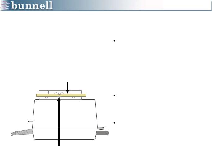
IDENTIFYING PROPER HUMIDIFICATION
It is important to identify proper humidification of the gas through the circuit. You can do this by observing the degree of mist in the green portion of the circuit tubing between the Patient Box and the LifePort adapter.
Proper humidification looks similar to the mist you would see when breathing on a mirror or against a car window on a cold winter day.
Excess humidification exhibits a collection of water pooling continuously in the clear portion of the circuit tubing between the cartridge and the Patient Box. The water may even begin to march into the patient‟s endotracheal tube.
This condition can be alleviated by lowering the set CARTRIDGE temperature by 1-2o C.
Insufficient humidification will be indicated by the green circuit tubing being dry.
Examples of proper, over, and under humidification are illustrated on the left.
It is important to see condensation in the green portion of the circuit between the Patient Box and the LifePort adapter. This condensation is an indication that the gas has reached 100% relative humidity.
25
Chapter 6
START UP
Objectives
1.Learn how to determine initial settings for high-frequency ventilation.
2.Learn to balance the conventional and high frequency ventilators to achieve better blood gases while using less pressure.
3.Understand the changes in monitored PEEP level that can occur when initiating high-frequency ventilation.
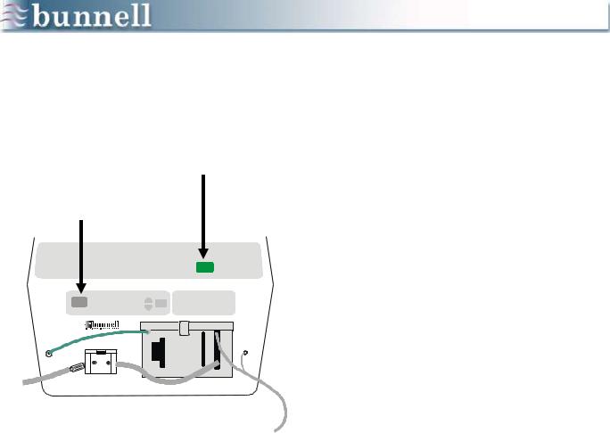
Attach to pressure monitoring port on
‘Patient Box
Attach CV circuit
Attach Life
Pulse Circuit
The following procedures describe how to prepare the Life Pulse for start up:
1.Secure the caps on the LifePort adapter.
2.Replace the endotracheal tube adapter with the LifePort adapter once a successful test sequence has been completed, and while the Life Pulse is still in the Standby mode.
3.Reattach the patient to the conventional ventilator by connecting the conventional circuit to the 15-mm opening of the LifePort.
4.Once the patient has been stabilized on the conventional ventilator, make the LifePort adapter connections to the Patient Box and Life Pulse circuit while the Life Pulse is in the Standby mode.
5.Connect the pressure monitoring tube of the LifePort adapter to the Patient Box and connect the Life Pulse circuit to the Jet port on the side of the LifePort adapter.
26

MEASURING & DISPLAYING PRESSURES
10 sec. |
2nd 80 sec. |
|
display |
||
|
1st 80 sec. display
Once the pressure monitoring tube of the LifePort adapter has been connected to the Patient Box, the Life Pulse, in its Standby mode, will begin to monitor the pressures being delivered by the conventional ventilator or other high frequency ventilator and update them in the MONITOR section every 10 seconds.
It will take about a minute and a half for the MONITOR to display an accurate PIP, PEEP, and MAP being delivered by the conventional ventilator or HFOV.
In the Standby mode, the Life Pulse monitors and displays the airway pressures as if measured at the distal tip of the ET tube. These pressures may or may not be different from the pressures displayed on the conventional ventilator.
Remember that the conventional ventilator displays pressures measured proximally while the Life Pulse displays approximations of distal pressures. We recommend that start up decisions be based on the pressures displayed in the Life Pulse‟s MONITOR section.
27
 Loading...