

Bunn Coffee Maker RL Installation Manual

Reach-in Merchandisers
®
Medium and Low Temperature
IMPORTANT
Keep in store for
future reference!
MANUAL- I/O REACH-IN
Installation &
Operation Manual
Shipped With Case Data Sheets
P/N 0387183_R
August 2015
English P/N 0387183
Spanish P/N 0517045
French P/N 0527085

P/N 0387183_R
Table of Contents
INSTALLATION
NSF Certification1-1
Location ....................................................... 1-1
Shipping Damage
Exterior Loading
Merchandisers Shipped With End Installed
Shipping Braces
Moving Through Narrow Entrances
Leveling
........................................................ 1-6
Joining
......................................................... 1-8
Splashguards
Installing Bumpers
........................................... 1-1
........................................... 1-2
......... 1-2
............................................. 1-2
.................. 1-3
............................................... 1-23
........................................ 1-24
REFRIGERATION / ELECTRICAL
Refrigerant .................................................... 2-1
Refrigerant Piping
Insulation
Branch Line Piping
Expansion Valve Adjustment
Refrigeration Thermostat
Defrost Termination Thermostat
Control Settings
Merchandiser Electrical Data
Field Wiring
Electrical Connections
Identification of Wiring
Wiring Color Code
.......................................... 2-1
...................................................... 2-2
........................................ 2-3
........................... 2-4
................................ 2-4
...................... 2-5
............................................ 2-7
........................... 2-9
................................................. 2-9
.................................... 2-9
.................................. 2-9
....................................... 2-10
START UP / OPERATION
Start up
.......................................................... 4-1
Stocking
Load Limits
Load Limit Profiles
Installing FDA/NSF Required Thermometer
........................................................ 4-1
.................................................... 4-1
.......................................... 4-1
..... 4-2
MAINTENANCE
Care and Cleaning ............................................ 5-1
Cleaning Honeycomb Assemblies
Cleaning Under Merchandisers
Removing Scratches from Bumper
........................ 5-2
......................... 5-2
...................... 5-2
SERVICE
Replacing Fan Motors and Blades ...................... 6-1
Replacing Electric Defrost Heaters
Replacing Drain Pan Heater
.................... 6-3
............................. 6-5
RLT with Gas Defrost Only: Replacing
Slave Plate Heater ........................................ 6-6
Servicing Vertical Lighting
Servicing Doors and Frames
Replacing Door or Door Frame Parts
Replacing Damaged Drain Fitting
Repairing Aluminum Coils
.............................. 6-7
............................. 6-7
................ 6-7
..................... 6-7
............................... 6-8
WARRANTY
DRIP PIPING AND SPLASHGUARDS
Waste Outlet and Water Seal ............................ 3-1
Installing Drip Piping
Drip Piping Lineup Arrangements
Installing Splashguards
Sealing Splashguard to Floor
..................................... 3-1
................... 3-4
................................... 3-5
........................... 3-6
IMPORTANT
KEEP IN STORE FOR FUTURE REFERENCE
Quality that sets industry standards!
This merchandiser is NSF® certified.
12999 St. Charles Rock Road • Bridgeton, MO 63044-2483
U.S. & Canada 1-800-922-1919 • Mexico 1-800-890-2900
www.hussmann.com
© 2015 Hussmann Corporation
iv Contents
INSTALLATION
TOOL LIST
Unloading From Trailer:
Lever Bar (also know as a Mule,
Johnson Bar, J-bar, Lever Dolly,
and pry lever)
Moving Dolly
Setting Case Line-Up:
Level, 4 ft suggested
Ratchet
¼ in. Socket
5
/16 in. Socket
½ in. Socket
Battery Drill/Screw Gun
Caulking Gun
10 in. Adjustable Crescent Wrench
ANSI Z535.5 DEFINITIONS
• DANGER – Indicate[s] a hazardous
situation which, if not avoided, will result
!
in death or serious injury.
• WARNING – Indicate[s] a hazardous
!
situation which, if not avoided, could
result in death or serious injury.
• CAUTION – Indicate[s] a hazardous sit-
!
uation which, if not avoided, could result
in minor or moderate injury.
• NOTICE – Not related to personal injury –
Indicates[s] situations, which if not avoided,
could result in damage to equipment.
REVISION HISTORY
REVISION R — JULY 2015
1.Replaced RLT drawings in Section 1; New Drawing
Page 2-6, 2-7, 4-2, wording on 6-2 and 6-4,
removed drawing 6-4.
P/N 0387183_R
REVISION Q — MAY 2015
1. Redesigned manual to 1/2 letter size
REVISION P — OCTOBER 2014
1. California Warning Statement, Page 1-2;
changed to 2 in. partition kit, Page 1-7; Shim
location, Page 1-6; End Caps, Page 1-8;
Removed screws, Page 2-2; Time Termination,
Page 2-8, 2-9; No thread sealer, Page 3-2, 3-3;
RLT load limit drawing, Page 4-2; Ammonia
cleaners, Page 5-3; Number 11, Page 6-1, 6-2;
Heater drawings, Page 6-4, 6-5; Removed number 2 teflon tape, Page 6-7.
U.S. & Canada 1-800-922-1919 • Mexico 1-800-890-2900 • WWW.HUSSMANN.COM

P/N 0387183_R
REVISION N — APRIL 2013
1. Inserted Joining Instructions,
Pages 1-8 - 1-22
REVISION M — MARCH 2013
1. Revised caution note on page 1-1; added to
Page 4-1.
REVISION L — AUGUST 2012
1. Updated instructions for moving case through
small doors, Section 1.
REVISION K — JULY 2012
1. Included instructions for clearing smaller store
entrances, Section 1. Ice cream note added to
Page 4-1.
REVISION J — APRIL 2012
1. Corrected Table of Contents, page iii.
REVISION I — NOT ISSUED
REVISION H — MARCH 2012
1. Amended Installing Drip Piping procedure,
Page 3-2.
REVISION G — MARCH 2010
1. Revised Installing Drip Piping procedure,
Pages 3-1 through 3-6.
REVISION E — JANUARY 2009
1. Added page division lines for thermometer,
Page 4-3.
2. Added heater front and rear drawing,
Page6-3.
3. Changed shimming drawing, Page 1-3.
REVISION D — SEPTEMBER 2007
1. Added front panel text and illustration, Page
1-2.
2. Clarified shimming directions, Page 1-3.
3. Added RLT information throughout.
4. Added note to remove bumper protective film,
Page 1-6.
5. Added information on Always*Clear™ glass,
page 5-1.
6. Removed reference to Anthony doors, Page
6-5.
7. Added repairing aluminum coil, Page 6-12.
8. Changed warranty page.
9. Added Installation Tool List, Page iv.
10. Added revision history, Page iv.
REVISION C — JUNE 2002
1. Added NSF information, Pages 1-1,4-2
through 4-4.
2. Sections 2 through 6 are completely
rewritten.
3. Changed warranty to March 15,2002.
REVISION F — DECEMBER 2009
1. Changed shimming drawing, Page 1-3.
2. Updated drip piping pitch, Page 3-1.
3. Added page division lines for thermometer,
Page4-3.
4. Added cleaning stainless steel rails,
Page5-2.
5. Added heater front and rear drawing,
Page6-3.
6. Updated warnings and cautions throughout
7. Added new back cover
HUSSMANN CORPORATION, BRIDGETON, MO 63044-2483 U.S.A.
Reach-In
P/N 0387183_R 1-1
INSTALLATION
NSF CERTIFICATION
These merchandisers are manufactured to meet ANSI
/ National Sanitation Foundation (NSF®) Standard
#7 requirements. Proper installation is required to
maintain certification. Near the serial plate, each case
carries a label identifying the type of application for
which the case was certified.
ANSI/NSF-7 Type I – Display Refrigerator / Freezer
Intended for 75°F / 55%RH Ambient Application
ANSI/NSF-7 Type II – Display Refrigerator / Freezer
Intended for 80°F / 55%RH Ambient Application
ANSI/NSF-7 – Display Refrigerator
Intended for Bulk Produce
LOCATION
These merchandisers are designed for displaying products in air conditioned stores where temperature is
maintained at or below the ANSI/NSF-7 specified level
and relative humidity is maintained at or below 55%.
Placing refrigerated merchandisers in direct sunlight,
near hot tables or near other heat sources could
impair their efficiency.
Like other merchandisers, these are sensitive to air disturbances. Air currents passing around merchandisers
will seriously impair their operation. Do NOT allow
air conditioning, electric fans, open doors or windows,
etc. to create air currents around the merchandisers.
Product should always be maintained at proper temperature. This means that from the time the product
is received, through storage, preparation and display,
the temperature of the product must be controlled to
maximize the life of the product.
SHIPPING DAMAGE
All equipment should be thoroughly examined for
shipping damage before and during unloading.
This equipment has been carefully inspected at our
factory. Any claim for loss or damage must be made
to the carrier. The carrier will provide any necessary
inspection reports and/or claim forms.
Apparent Loss or Damage
If there is an obvious loss or damage, it must be noted
on the freight bill or express receipt and signed by the
carrier’s agent; otherwise, carrier may refuse claim.
The carrier will supply necessary forms.
Concealed Loss or Damage
When loss or damage is not apparent until after
equipment is uncrated, a claim for concealed damage
is made. Upon discovering damage, make request in
writing to carrier for inspection within 15 days and
retain all packing. The carrier will supply inspection
report and required claim forms.
To prevent sweating on the exterior surfaces
of merchandisers, there must be
ance of 4 inch es (102 mm ) between the merchan-
a m inimum clear -
Do not store items or ammable
materials atop the unit.
disers and other fixtures or walls.
HUSSMANN CORPORATION • BRIDGETON, MO 63044-2483 U.S.A.
Do not walk on case.
Reach-In
1-2 InstallatIon
EXTERIOR LOADING
Do NOT walk on top of merchandisers or damage to
the merchandisers and serious personal injury could
occur.
They are noT sTrucTurally designed To supporT
excessive exTernal loading such as the weight of
a person. Do not store items or flammable materials
atop the unit.
For California Businesses:
This product may contain chemicals
known to the State of California to
cause cancer, birth defects, or other
This warning is the result of the California State law
known as the California Safe Drinking Water and Toxic
Enforcement Act of 1986, which is commonly referred
to as “Proposition 65.”
This warning does not mean that Hussmann products will cause cancer or reproductive harm, or is in
violation of any product-safety standards or requirements. As claried by the California State government,
Proposition 65 can be considered more of a ‘right to
know’ law than a pure product safety law. When used
as designed, Hussmann believes that our products are
not harmful. We provide the Proposition 65 warning
to stay in compliance with California State law. It is
your responsibility to provide accurate Proposition 65
warning labels to your customers when necessary. For
more information on Proposition 65, please visit the
California State government website.
reproductive harm.
MERCHANDISERS SHIPPED WITH
END INSTALLED
If the case was shipped with the end installed, two
long bolts were used to hold the shipping brace to the
end. If the shipping bolts are reinserted after removing the brace, they will extend into the product area
and may damage the coil.
re pla ce The se bol Ts wi Th The sh or Ter bo lTs
pr ovi ded .
Th ere for e, be sur e T o
Be careful not to damage the factory-installed end
while moving the merchandiser. Make sure that tools
are positioned past the end and beneath the merchandiser’s support bar.
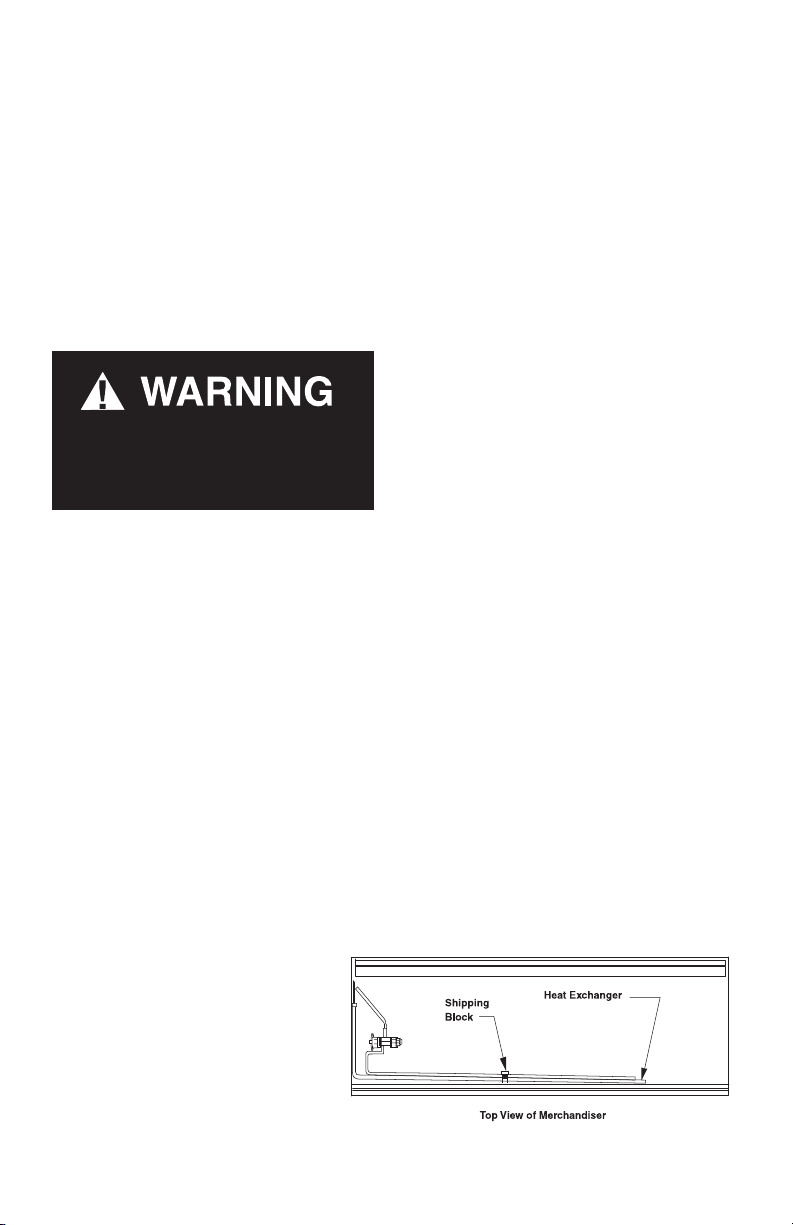
SHIPPING BRACES
Move the merchandiser as close as possible to its permanent location and then remove all packaging. Check
for damage before discarding packaging. Remove all
separately packed accessories such as kits and shelves.
Locate the shipping block in the center of the heat
exchanger (see illustration), and remove it before
piping the merchandiser. This block was installed to
minimize shipping vibration.
P/N 0387183_R
U.S. & Canada 1-800-922-1919 • Mexico 1-800-890-2900 • WWW.HUSSMANN.COM
P/N 0387183_R 1-3
MOVING MERCHANDISER THROUGH
NARROW STORE ENTRANCES
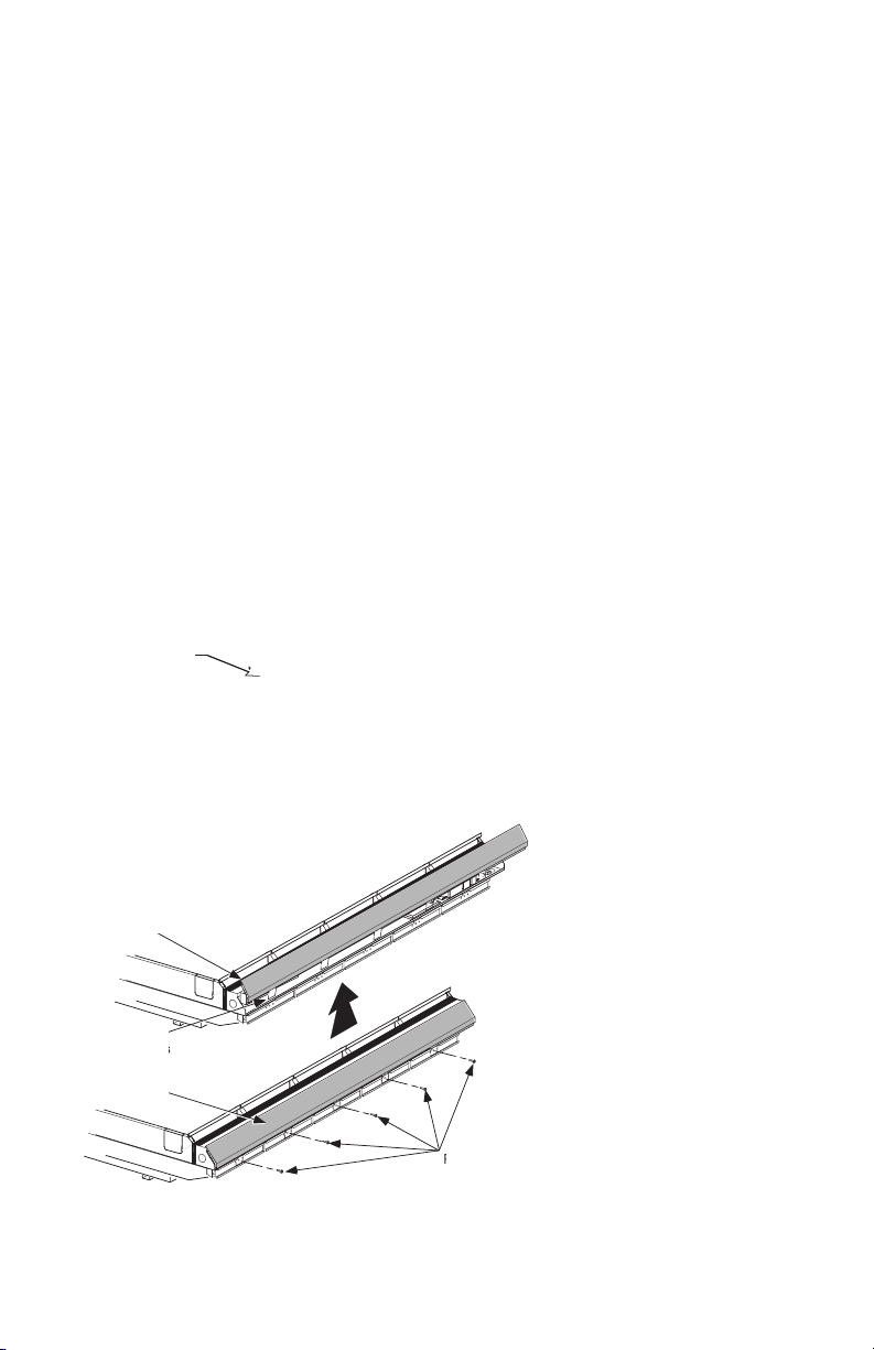
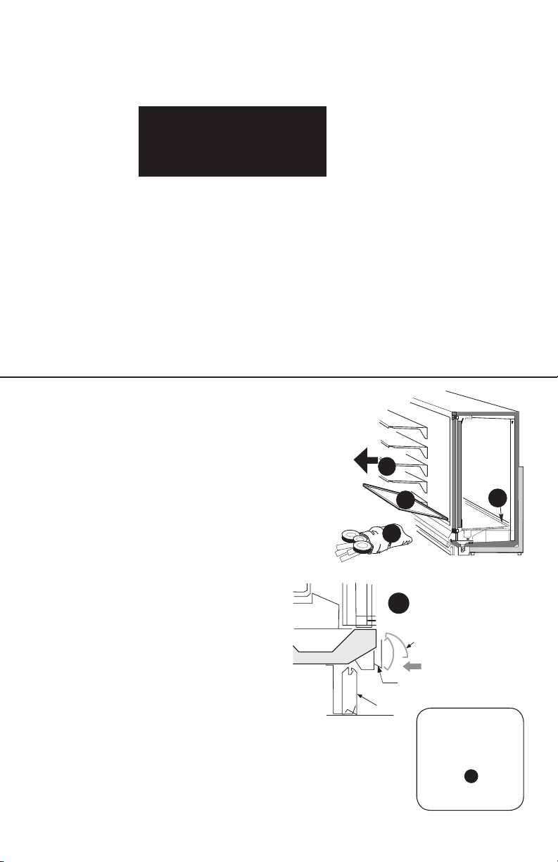
2. Remove the front bumper. Pull from the
Some exterior merchandiser parts may be disassembled
bottom and set aside.
for transit access through small doors or passage ways.
This procedure takes approximately 30 minutes to
disassemble and reassemble one case. Contact your
Hussmann representative to see if store merchandisers
have this kit option. The case height without these
components installed on top is 82.75 in. (2102 mm).
Case depth is 35.5 in. with handles, wireway pan and
external frames removed.
Follow the steps below to decrease the
merchandiser profile for narrow access:
1. Remove the door handles.
Remove
Screws from
Door Handle
Edge Fits over
Wireway
Tabs t in
Retainer Slots
Front Panel
3. Remove the lower front panel to access the
wireway.
Remove Screws
HUSSMANN CORPORATION • BRIDGETON, MO 63044-2483 U.S.A.
Reach-In
1-4 InstallatIon
4. Remove the screws that attach the wireway pan to
the bottom assembly.
5. Detach the rubber and plastic gromets from the
wireway pan.
6. Remove the screws that attach the grounding lug to
the wireway pan.
7. Slide the wireway pan out, and remove it from the
case. Bumper brackets and supports are attached to
wireway pan. Removing the pan will remove the entire
assembly.
8. Remove the back, external braces from the rear of
the case as shown below. Braces will slide straight
back away from the case when nuts and screws are
removed.
6 nuts and 1
bottom screw per
external brace
P/N 0387183_R
Bottom screw is located approximately 10 inches inboard from the rear of
the case. Bottom screw location on
removed rear brace.
U.S. & Canada 1-800-922-1919 • Mexico 1-800-890-2900 • WWW.HUSSMANN.COM
P/N 0387183_R 1-5
Check the following before the rear of the case is positioned at its final location according to the store plan:
1. The external braces must be reinstalled
with (6) nuts per brace, torqued to 24 foot
pounds.
Do not walk on top of merchandiser.
Do not store items or
ammable materials atop the unit.”
FINAL LOCATION
Once the case reaches its final location, reassemble the
wireway and door handles as follows:
1. Reinstall wireway pan in reverse order of removal.
2. The ground lug must be reinstalled using the
screws provided.
3. Replace the conduit connectors and plastic gromets to the wireway pan.
LEVELING
Merchandisers must be installed level to ensure proper
operation of the refrigeration system and to ensure
proper drainage of defrost water. When leveling mer-
chandisers, use a carpenter’s level as shown.
Metal leveling shims or wedges are provided with each
merchandiser for use if needed.
Rear external frames must be
reinstalled securely before setting
or unloading shelves.
o not walk on top of the merchandIser.
D
do not place heavy objects on case.
4. Replace wireway cover, bumper and door handles.
HUSSMANN CORPORATION • BRIDGETON, MO 63044-2483 U.S.A.
Reach-In
1-6 InstallatIon
LEVELING
Merchandisers must be installed level to ensure
proper operation of the refrigeration system and
to ensure proper drainage of defrost water. When
leveling merchandisers, use a carpenter’s level as
shown.
Metal leveling shims or wedges are provided with
each merchandiser for use if needed.
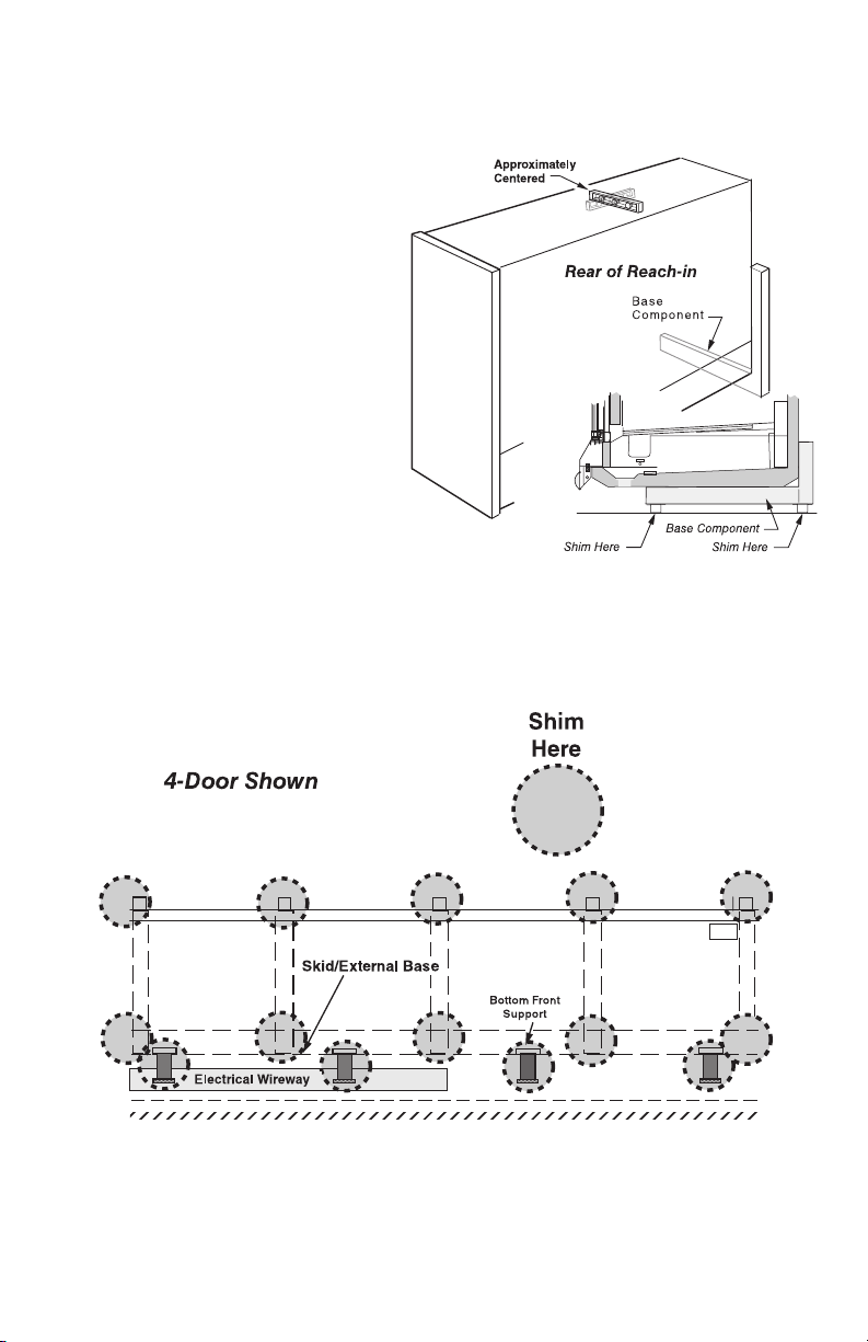
NOTE:
Be gi n li neu p le ve li ng f ro m t he
hi gh es t po in t o f th e st ore f lo or .
Place shims under the rail and make sure that they
are positioned at a base component (crossbar).
This transfers the weight directly from the loaded
case through to the floor.
Placing shims at other locations will cause uneven
distribution of weight leading to piping leaks, as well
as sagging or wracked doors.
P/N 0387183_R
Back
Front
U.S. & Canada 1-800-922-1919 • Mexico 1-800-890-2900 • WWW.HUSSMANN.COM

P/N 0387183_R 1-7
DOOR ADJUSTMENT
After leveling and joining the merchandisers, adjust
and level doors according to manufacturer’s instructions
shipped with each product. Factory settings may be
lost due to vibration during shipment.
JOINING
Sectional construction means that two or more merchandisers may be joined in line yielding one long
continuous display requiring only one pair of ends.
Joining kits and instructions are shipped with each
merchandiser.
To join like fixtures, a joining kit is required. To
join unlike fixtures, or like fixtures operating at different temperatures, a 2inch (51mm) partition kit
is required. To join same temperature merchandisers
on different defrost cycles, a plexiglass partition kit is
required.
all jo inTs musT be air-Ti ghT To pre venT forma-
Tion o f ice or condensaTi on.
Refer to the instructions on the next page.
HUSSMANN CORPORATION • BRIDGETON, MO 63044-2483 U.S.A.
Reach-In
1-8 InstallatIon
Joining Instructions
RL / RM / RMF, RLTM
RLN / RMN / RLNI / RLNIE
Splashguard brackets must
be installed before piping or
PARTS LIST
Item
Quantity Description
RL/RM RLN RLNI
RM/RMF RMN RLNIE RLTM
1. 2 2 4 2 Donut Gasket
2. 1 1 2 2 Gasket, 1 x
3. 1 1 2 1 Gasket,
4. 8 8 14 6 Cap Screw
5. 8 8 14 6 Split Lock Washers 5/16
6. 1 1 2 1 Joint Molding
7. 5 5 10 5 Binder Post and Screw
8. 1 1 2 1 Splice Connector
NOTE: Be sure first merchandiser has been leveled
according to the main installation instruction.
Carefully unpack and inspect the joining parts listed
above to verify completeness and that there is no
damage.
wiring case.
Joining Instructions
1
/2 x 180 in.
1
/2 x 1/4 x 180 in.
5
/16 -18 x 11/4
B
C
E
D
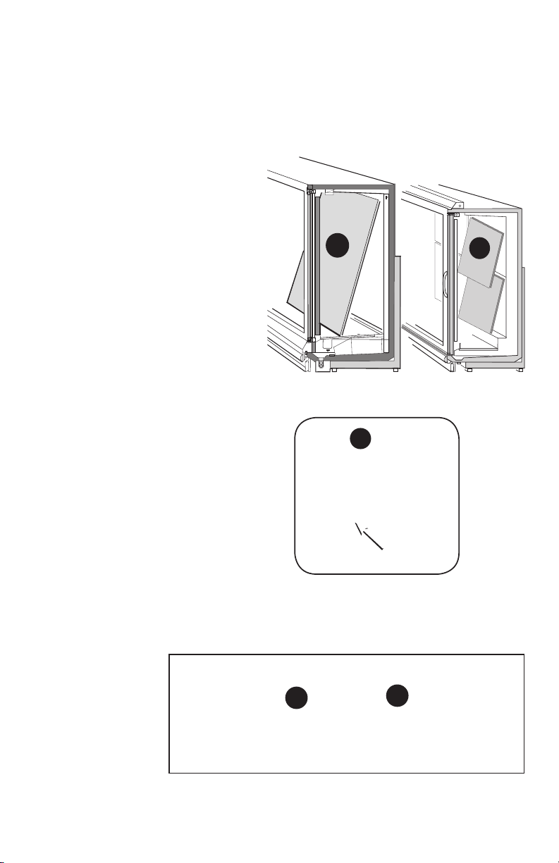
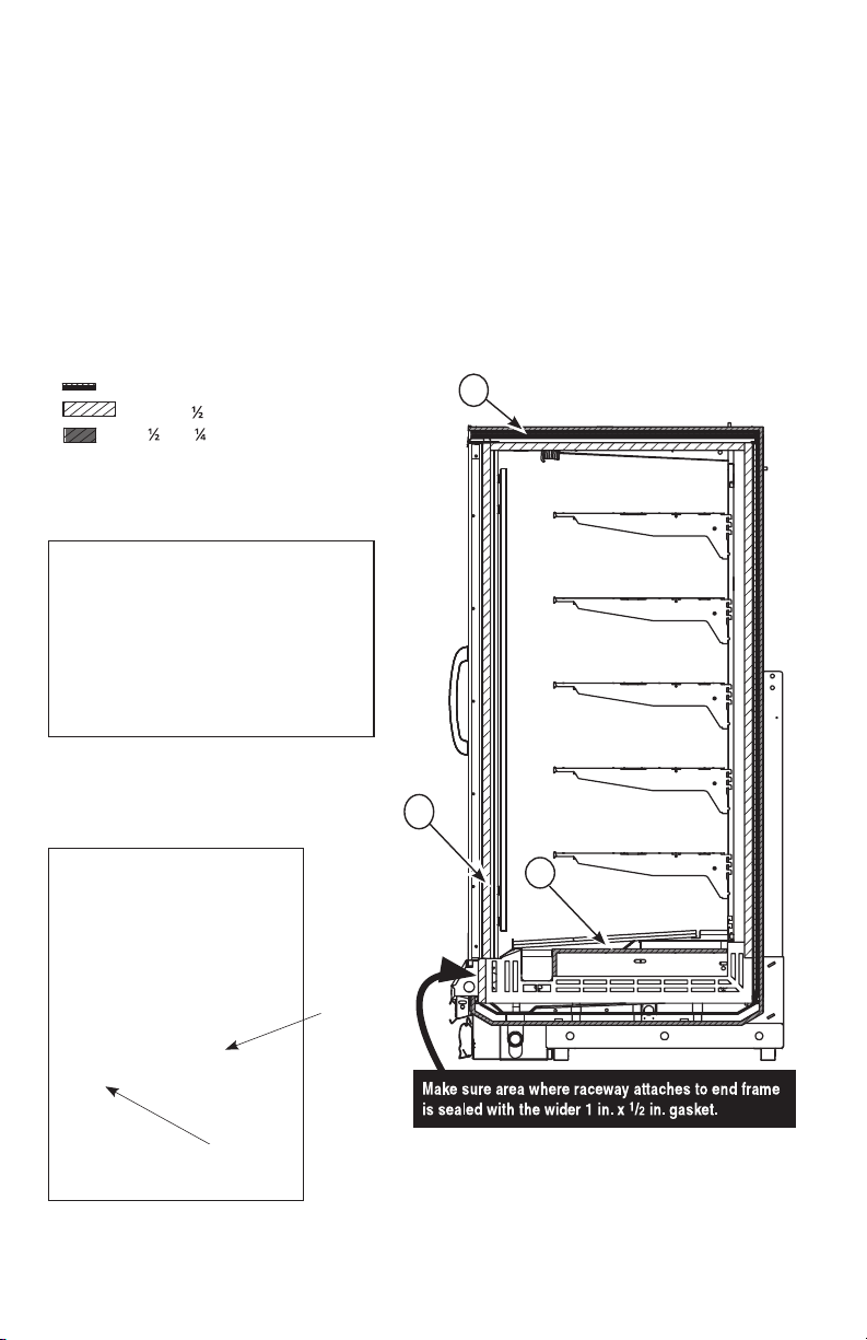
Prepare cases for joining (both sides of
1
islands) as shown in Figure 1.
A. Remove bumpers, rails, packing materials,
and splashguards from the both cases.
B. Remove shelves (if installed).
C. Remove display racks and pans from
ends to be joined.
D. Remove plenum covers
P/N 0387183_R
U.S. & Canada 1-800-922-1919 • Mexico 1-800-890-2900 • WWW.HUSSMANN.COM
RLTM
Figure 1. Prepare Cases
SIDE VIEW
A
A
Bumper
Retainer
Splashguard
Bumper
C
P/N 0387183_R 1-9
RL / RM / RMF
RLN / RMN
and RLNI
E. Remove back panels from ends to be
joined by lifting up and out near the bottom. No tools are necessary. The RLTM
models have upper and lower back panels
that must be removed.
F. Remove joint molding from any door
frames that will be joined to another case.
G. RLNI Only: Remove screws and interior top panel on both sides of the island
case end to be joined (see Figure 1).
E
F
Alignment Pin
RLTM
E
G
RLNI Only
HUSSMANN CORPORATION • BRIDGETON, MO 63044-2483 U.S.A.
G
Reach-In

1-10 InstallatIon
Shipping
Block
Figure 2. Remove Shipping Block
(One From Each Side of Island Models)
Locate and remove the shipping block in the
2
center of the heat exchanger in the interior
bottom of each case, see Figure 2.
Snap a chalk line on the floor to use as a guide
for positioning the front of the cases in the
line-up. The front base frame should be on the
chalk line.
Once cases are close to final placement, remove
3
the shipping braces from the ends to be joined,
see Figure 3. Discard bolts and flat washers
used to hold shipping braces. Bolts are too
long to be used for joining.
Do not use shipping bolts to join cases!
RMN
P/N 0387183_R
Shipping Brace
RLNI / RLNI
Figure 3. Remove Shipping Braces
U.S. & Canada 1-800-922-1919 • Mexico 1-800-890-2900 • WWW.HUSSMANN.COM
P/N 0387183_R 1-11
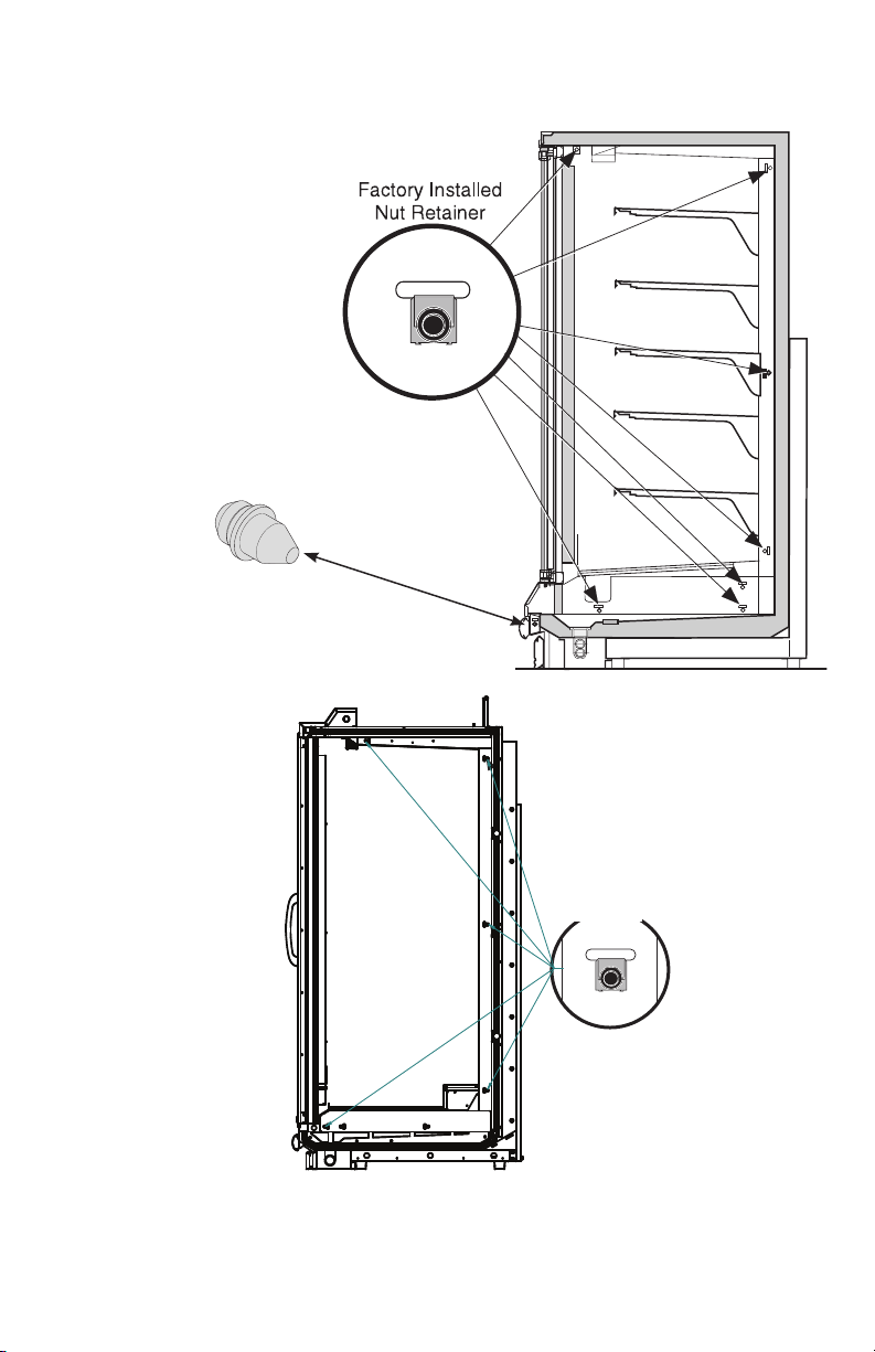
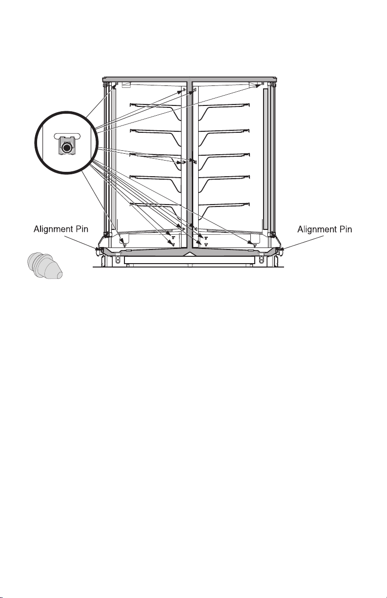
If not already installed make
sure NutRetainers and
4
Alignment Pins are in place in
the right end frame as shown
in Figure 4A or 4B.
RL / RM / RMF
and
RLN / RMN
Alignment Pin
RLTM
RLT has no
Alignment Pin
Figure 4A. Verify Nut Retainer Installation
HUSSMANN CORPORATION • BRIDGETON, MO 63044-2483 U.S.A.
Factory Installed
Nut Retainer
Reach-In
1-12 InstallatIon
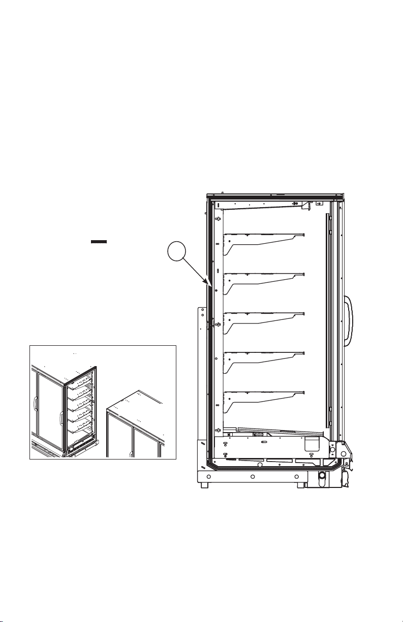
RLNI
P/N 0387183_R
U.S. & Canada 1-800-922-1919 • Mexico 1-800-890-2900 • WWW.HUSSMANN.COM
P/N 0387183_R 1-13
Left End
PadShoeSealer
in
1- Donut
Apply Donut Gasket– 1 in recess around both
5
left end as shown in Figure 5A, Part 1; 5B or
5C, Part 1, and right end frames as shown in
Figure 5A, Part 2; 5B or 5C, Part 2.
RL / RM / RMF
and
RLN /
RMN
Right End Case
Apply the wider Foam Tape Gasket — 2
around the right end frame as shown in Figure
5A, Part 2, 5B or 5C, Part 2.
Left End Case
F
1
R
O
N
T
Left End Case
Figure 5A, Part 1. Apply Gasket to Left End of
RL/RM/RMF and RLN/RMN
HUSSMANN CORPORATION • BRIDGETON, MO 63044-2483 U.S.A.
Reach-In
1-14 InstallatIon
Right End
Left End
F
R
O
N
T
1- Donut
2- 1 in x
in
3- in x in
Use all three gaskets
When applying an end
assembly.
assembly.
Apply Pad Shoe Sealer first,
then apply the narrower Foam
Tape Gasket — 3 around
the perimeter of the right end
frame outside of the donut
gasket as shown in Figure 5A,
Part 2, 5B or 5C, Part 2.
1- Donut
2- 1 in x
3- in x in
Use all three gaskets
When applying an end
notes:
1. The perimeter gasket, Item 3,
is required by NSF.
2. Butyl is NOT an acceptable
substitute for donut or foam
gasket.
in
• Lap gaskets at lower
corners.
• Check that there are no
gaps between gasket and case.
• Do not stretch gasket,
especially around corners.
To make sharp corners,paper
backing can be torn without
removing from gasket.
RL / RM /
RMF
and
RLN / RMN
F
R
O
N
T
2
1
Right End Case
ALL MODELS: Apply
gasket between
wipes.
3
• Do not butt gaskets; always
lap joints.
• Remove paper backing after
gasket is applied to keep gasket
free of debris.
• Gasket has high tack
adhesive and must be properly
placed the first time.
Figure 5A, Part 2. Apply Gaskets to Right End of RL/RM/RMF and RLN/RMN
P/N 0387183_R
Pad Shoe
Sealer
Overlap
Gasket
U.S. & Canada 1-800-922-1919 • Mexico 1-800-890-2900 • WWW.HUSSMANN.COM
 Loading...