


JDF-4
JDF-4
S/N 0005473 & UP
! W
A
RN
I
N
G
Refrigeration Compressor and
Condensor Fan Motor only
INSTALLATION & OPERATING MANUAL
BUNN-O-MATIC CORPORATION
POST OFFICE BOX 3227
SPRINGFIELD, ILLINOIS 62708-3227
PHONE: (217) 529-6601 FAX: (217) 529-6644
To ensure you have the latest revision of the manual or to obtain the illustrated parts catalog, please visit the Bunn-O-Matic website,
at www.bunn.com. This is absolutely FREE, and the quickest way to obtain the latest catalog and manual updates. Contact Bunn-O-
Matic Corporation at 1-800-286-6070 to obtain a paper copy of the required Illustrated Parts Catalog mailed via U.S. Postal Service.
38218.0001D 02/08 ©2006 Bunn-O-Matic Corporation www.bunn.com
DISCONTINUED VERSION
The information in this manual
is no longer current.

2
38218.1 020608
BUNN-O-MATIC COMMERCIAL PRODUCT WARRANTY
Bunn-O-Matic Corp. (“BUNN”) warrants equipment manufactured by it as follows:
1) All equipment other than as specified below: 2 years parts and 1 year labor.
2) Electronic circuit and/or control boards: parts and labor for 3 years.
3) Compressors on refrigeration equipment: 5 years parts and 1 year labor.
4) Grinding burrs on coffee grinding equipment to grind coffee to meet original factory screen sieve analysis:
parts and labor for 3 years or 30,000 pounds of coffee, whichever comes first.
These warranty periods run from the date of installation BUNN warrants that the equipment manufactured by
it will be commercially free of defects in material and workmanship existing at the time of manufacture and
appearing within the applicable warranty period. This warranty does not apply to any equipment, component or
part that was not manufactured by BUNN or that, in BUNN’s judgment, has been affected by misuse, neglect,
alteration, improper installation or operation, improper maintenance or repair, damage or casualty. This warranty is
conditioned on the Buyer 1) giving BUNN prompt notice of any claim to be made under this warranty by telephone
at (217) 529-6601 or by writing to Post Office Box 3227, Springfield, Illinois 62708-3227; 2) if requested by
BUNN, shipping the defective equipment prepaid to an authorized BUNN service location; and 3) receiving prior
authorization from BUNN that the defective equipment is under warranty.
THE FOREGOING WARRANTY IS EXCLUSIVE AND IS IN LIEU OF ANY OTHER WARRANTY, WRITTEN OR
ORAL, EXPRESS OR IMPLIED, INCLUDING, BUT NOT LIMITED TO, ANY IMPLIED WARRANTY OF EITHER
MERCHANTABILITY OR FITNESS FOR A PARTICULAR PURPOSE. The agents, dealers or employees of BUNN
are not authorized to make modifications to this warranty or to make additional warranties that are binding on
BUNN. Accordingly, statements by such individuals, whether oral or written, do not constitute warranties and
should not be relied upon.
If BUNN determines in its sole discretion that the equipment does not conform to the warranty, BUNN, at its
exclusive option while the equipment is under warranty, shall either 1) provide at no charge replacement parts
and/or labor (during the applicable parts and labor warranty periods specified above) to repair the defective
components, provided that this repair is done by a BUNN Authorized Service Representative; or 2) shall replace
the equipment or refund the purchase price for the equipment.
THE BUYER’S REMEDY AGAINST BUNN FOR THE BREACH OF ANY OBLIGATION ARISING OUT OF THE SALE OF
THIS EQUIPMENT, WHETHER DERIVED FROM WARRANTY OR OTHERWISE, SHALL BE LIMITED, AT BUNN’S
SOLE OPTION AS SPECIFIED HEREIN, TO REPAIR, REPLACEMENT OR REFUND.
In no event shall BUNN be liable for any other damage or loss, including, but not limited to, lost profits, lost sales,
loss of use of equipment, claims of Buyer’s customers, cost of capital, cost of down time, cost of substitute
equipment, facilities or services, or any other special, incidental or consequential damages.
BrewWISE, BUNN Gourmet Ice, BUNN Pour-O-Matic, BUNN, Bunn-OMatic, Bunn-O-Matic, BUNNlink, BUNNserve, BUNN
Espress, DBC, Dr. Brew, Dual, EasyClear, EasyGard, Easy Pour, FlavorGard, Gourmet Ice, Gourmet Juice, High Intensity,
IMIX, Infusion Series, Legendary for Quality, The Mark of Quality in Beverage Equipment Worldwide, My Café, Power-
Logic, Safety-Fresh, Scale-Pro, Single, Smart Funnel, Smart Hopper, Soft Heat, SplashGard, System III, ThermoFresh,
392, AXIOM, Beverage Profit Calculator, Beverage Bar Creator, BrewLOGIC, BrewMETER, BrewWIZARD, BUNNSERVE,
BUNNsource, Coffee At Its Best, Cool Froth, Digital Brewer Control, Intellisteam, Nothing Brews Like a BUNN, Pouring
Profits, Pulse Wave, Quality Beverage Equipment Worldwide, Signature Series, Silver Series, Smart Heat, SmartWAVE,
Tea At Its Best, The Horizontal Red Line, Titan, Ultra, are either trademarks or registered trademarks of Bunn-O-Matic
Corporation.
3
USER NOTICES
Carefully read and follow all notices on the equipment and in this manual. They were written for your protec-
tion. All notices are to be kept in good condition. Replace any unreadable or damaged labels.
27442.0000
00986.0002
33461.0000
CHARGE
Type R134A, Amount 10 oz (283 gm)
Design Pressures:
High 335 psi (23 bar) (2.31 MPa)
Low 88 psi (6 bar) (0.61 MPa)
CONTENTS
Warranty ........................................................................................................................ 2
Introduction ................................................................................................................... 3
User Notices .................................................................................................................. 3
Initial Set-Up & Electrical Requirements ........................................................................ 4
CE Requirements ........................................................................................................... 4
Plumbing Requirements ................................................................................................ 5
Plumbing Hook-Up ........................................................................................................ 5
Operating Controls ......................................................................................................... 6
Initial Fill ........................................................................................................................ 8
Dispenser Use ................................................................................................................ 9
Cleaning ....................................................................................................................... 10
Adjustments & Optional Settings ................................................................................. 13
Function Lists .............................................................................................................. 18
Troubleshooting ........................................................................................................... 21
Coolant Diagram .......................................................................................................... 28
Schematic Wiring Diagram .......................................................................................... 29
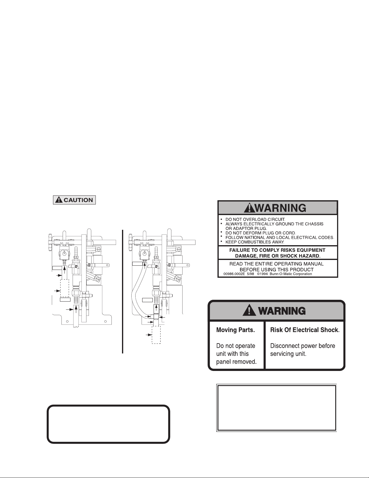
MAXIMUM RINSE WATER TEMPERATURE: 170˚F (76.6˚C)
Use Bunn-O-Matic tubing, part number 32759.10XX
(See Illustrated Parts Catalog for complete part number)
for hot water connection.
• Use Bunn-O-Matic tubing, part number 32759.10XX for all connections.
(See Illustrated Parts Catalog for complete part number)
• Clamp all hose connections with Bunn-O-Matic part number 21275.0003 (hose clamp)
34054.0000A 10/01 ©2001 BUNN-O-MATIC CORPORATION
NOTES:
Alternate Connection
(When Hot Water source is not available)
Hot Water Rinse Connection
RINSE WATER
CONNECTION
RINSE WATER
CONNECTION
Cold Water
Connection
MAIN WATER
CONNECTION
MAIN WATER
CONNECTION
3/8" x 3/8" x 3/8" Barb Tee
B.O.M. PN 32750.0000
(may be installed internal or
external to the dispenser)
Hot Water
Connection
(See Caution)
Cold Water
Connection
Install Water
Strainer Here
Install Water
Strainer Here
34054.0000
(Early Models prior to the Water Inlet Valve)
38218.1 030308
This equipment must be installed to comply
with the International Plumbing Code of the
International Code Council and the Food
Code Manual of the Food and Drug Adminis-
tration (FDA). For models installed outside
the U.S.A., comply with the applicable
Plumbing /Sanitation Code.
00656.0000

4
INITIAL SET-UP
CAUTION: The dispenser is very heavy! Use care when lifting or moving it. Use at least two people to lift or move
the dispenser. Place the dispenser on a sturdy counter or shelf able to support at least 230 lbs. (104.3 kg). The
JDF-4 is designed for indoor use only.
Set the dispenser on the counter where it will be used. The JDF-4 requires a minimum of 4 inches (102 mm)
of air clearance at the rear and 8 inches (203 mm) of air clearance above the dispenser. Minimal clearance is
required between the dispenser sides and the wall or another appliance. For optimum performance, do not let
warm air from surrounding machines blow on the JDF-4. Leave some space so the dispenser can be moved for
cleaning.
ELECTRICAL REQUIREMENTS
CAUTION: The dispenser must be disconnected from the power source until specified in Electrical Hook-Up.
The 120V rated dispenser has an attached cord set and requires a 2-wire, grounded, individual branch circuit
rated 120 volts ac, 15 amp, single phase, 60Hz. The mating connector must be a NEMA5-15R. (Refer to the
dataplate for exact electrical requirements.)
The 230V rated dispenser has an attached cord set and requires an attachment plug cap rated at least 230 volts
ac, 15 amp. The attachment plug cap must meet with applicable national/local electrical codes.
ELECTRICAL HOOK-UP
CAUTION: Improper electrical installation will damage electronic components.
1. An electrician must provide electrical service as specified.
2. Using a voltmeter, check the voltage and color coding of each conductor at the electrical source.
3. Connect the dispenser to the power source.
4. If plumbing is to be hooked up later, be sure the dispenser is disconnected from the power source. If plumb-
ing has been hooked up, the dispenser is ready for Initial Fill.
38218.1 030308
CE REQUIREMENTS
• This appliance must be installed in locations where it can be overseen by trained personnel.
• For proper operation, this appliance must be installed where the temperature is between 0°C to 35°C.
• Appliance shall not be tilted more than 10° for safe operation.
• An electrician must provide electrical service as specied in conformance with all local and national codes
• This appliance must not be cleaned by water jet.
• This appliance is not intended for use by persons (including children) with reduced physical, sensory or mental capa-
bilities, or lack of experience and knowledge, unless they have been given instructions concerning use of this appli-
ance by a person responsible for its safety.
• If the power cord is ever damaged, it must be replaced by the manufacturer or authorized service personel with a special
cord available from the manufacturer or its authorized service personel in order to avoid a hazard.
5
PLUMBING REQUIREMENTS
This dispenser must be connected to a COLD WATER system with operating pressure between 20 and 100 psi (138
and 690 kPa). This water source must be capable of producing a minimum flow rate of 3 fluid ounces (88.7 milliliters) per
second. A shut off valve should be installed in the line before the dispenser. Install a regulator in the line when pressure is
greater than 100 psi (690 kPa) to reduce it to 50 psi (345 kPa). Also if the install location experiences pressure fluctuations
greater than 20 psi (138kPa). The main water inlet is a 3/8” (9.52 mm) male flare.
Additionally, the dispenser’s rinse connection may be connected to a HOT WATER system.
Caution: MAXIMUM RINSE WATER TEMPERATURE: 170 degrees F (76.6 degrees C)
Use BUNN-O-MATIC tubing, part number 34325.10_ _ (see Illustrated Parts Catalog for complete part number) for hot
water connection.
The rinse water operating pressure must be between 20 and 100 psi (138 and 690 kPa). A shut off valve should be
installed in the line before the dispenser. Install a regulator in the line when pressure is greater than 100 psi (690 kPa) to
reduce it to 50 psi (345 kPa). The rinse water inlet is a 3/8” (9.52 mm) barb connection.
NOTE- At least 18 inches (457 mm) of an FDA approved flexible beverage tubing, such as reinforced braided polyethylene,
before the dispenser will facilitate movement to clean the countertop. It can be purchased direct from BUNN-O-MATIC (part
number 34325.10_ _ [see Illustrated Parts Catalog for complete part number.]) BUNN-O-MATIC does not recommend the
use of saddle valves to install the dispenser. The size and shape of the hole(s) made in the supply line(s) by saddle valves
may restrict water flow.
NOTE- On early models dispensers without water inlet valve, a water strainer (Bunn-O-Matic part number 23720.1000)
should be installed in line, prior to the flexible water line. This strainer is supplied loose with the dispenser.
NOTE - Water pipe connections and fixtures directly connected to a potable water supply shall be sized, installed and
maintained in accordance with federal, state and local codes.
This equipment must be installed to comply with the International Plumbing Code of the International
Code Council and the Food Code Manual of the Food and Drug Administration (FDA). For models installed
outside the U.S.A., you must comply with the applicable Plumbing/Sanitation Code for your area.
38218.1 030308
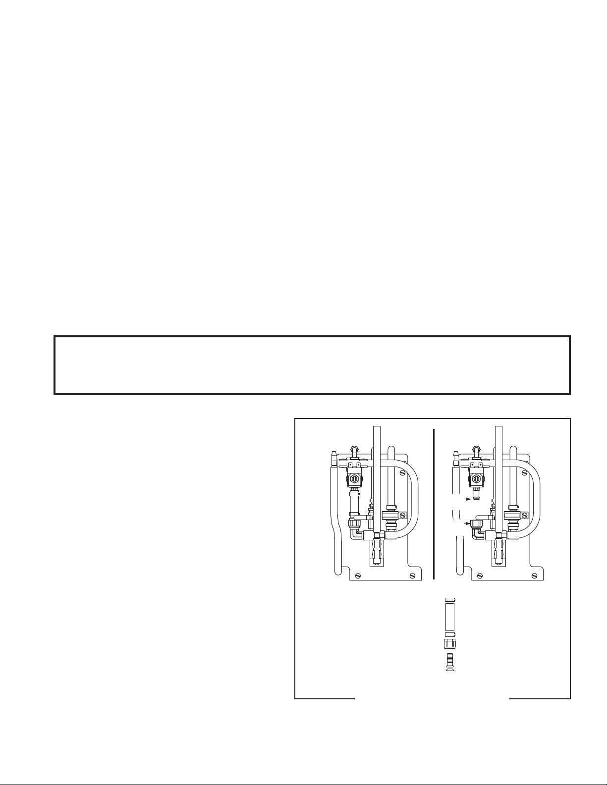
PLUMBING HOOKUP
CAUTION: The dispenser must be disconnected
from the power source throughout the plumbing
hookup.
For early models without the water inlet valve,
plumbing connections are located behind the
dispenser’s splash panel. Hoses are connected to
the water valve(s) and travel under the water bath
tank and out the rear of the dispenser. A .38" female
flare connector is attached to the hose and connects
to the supplied water strainer. The water strainer
is shipped loose, taped to the bottom panel.
For late models with the water inlet valve, a
hose assembly from the water bath shut-off valve
travels over the top of the water bath tank to the
product coil and the water inlet valve. A .75" hose
to .38" male flare fitting attaches to the water inlet
valve.
To access the water valves in the front of the
dispenser, remove the drip tray assembly; remove
the two screws securing the splash panel to the
dispenser and remove the splash panel.
Hot Water Rinse Connection
Hose assembly to be
replaced after Hot Water Rinse
Hot Water
Connection
(See Caution)
Install Cap
with Hot Water
Connection
P2476
FIG 1 Plumbing Connections
6
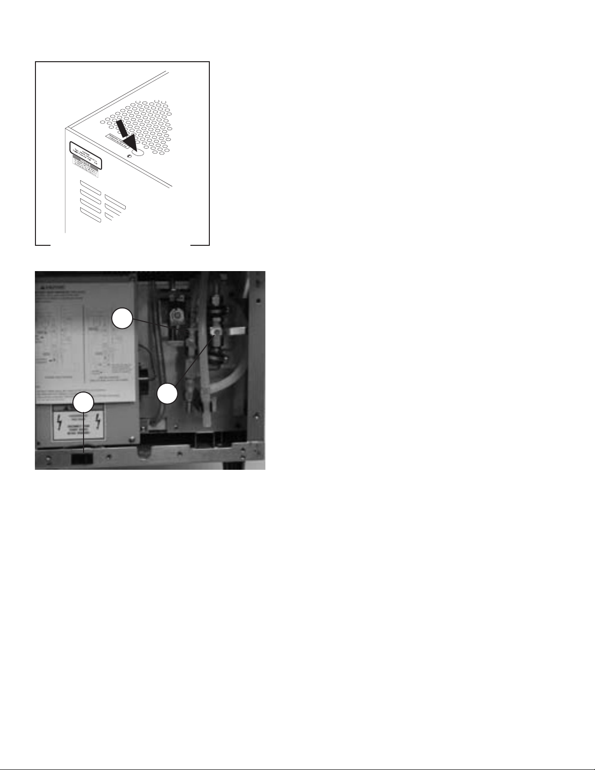
OPERATING CONTROLS
FIG 2 Refrigeration Switch
FIG 3 Sanitize Switch & Water Valves
A. Sanitize Switch
B. Water Bath Valve
C. Main Water Valve (Early Models)
C
P2262.60
P2479
A
B
Refrigeration Switch
The refrigeration switch is located on the top of the dispenser near the
left rear corner. This switch controls power to the compressor and the
condenser fan motor.
38218.1 030306
Sanitize Switch
The sanitize switch is located behind the drip tray in the
lower left corner of the chassis. The drip tray can be removed
to provide easy access to the switch. The sanitize switch
is used to enter and exit the sanitize mode and to initiate
the sanitize automatic cycle. Refer to Weekly Sanitizing in
the Cleaning section for detailed instructions on the use of
this switch.
Water Bath Valve
This valve is manually operated and located above the drip
tray, behind the splash panel. The drip tray and splash panel
must be removed to gain access to the valve. On early mod-
els, the valve on the right (large) is the main water valve.
Refer to the Initial Fill section for detailed instructions on
the use of these valves.
7
OPERATING CONTROLS (cont.)
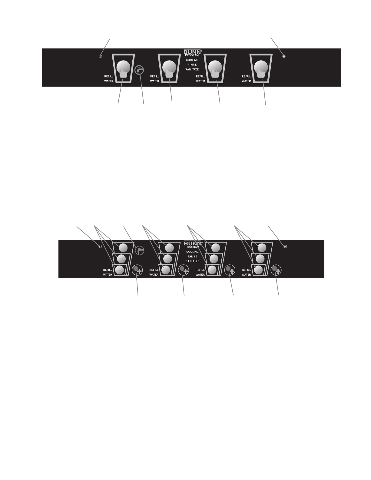
FIG 4 Press and Hold Models
A. Product Dispense Switch
Pressing and holding switch will initiate product flow from the respective nozzle; releasing the switch will
stop the flow.
B. Chilled Water Dispense Switch
Pressing and holding switch will initiate chilled water flow from the nozzle; releasing the switch will stop the
flow.
C. Hidden Switch
These switches are used to access, change and exit the dispenser program mode.
FIG 5 Portion Control Models
B. Chilled Water Dispense Switch
Pressing and holding switch will initiate chilled water flow from the nozzle; releasing the switch will stop the
flow.
C. Hidden Switch
These switches are used to access, change and exit the dispenser program mode.
D. Product Dispense Switch
Momentarily pressing and releasing one of the switches will initiate a timed dispense. Each station has three
different timed dispenses which are preset at the factory. Refer to DISPENSER USE section for preset volumes
and adjustment procedures.
E. Plus/Stop Switch
This switch can be used to “top-off” a beverage. Pressing and holding switch will initiate product flow from
the respective nozzle; releasing the switch will stop the flow. Momentarily pressing this switch during a timed
dispense will stop the flow.
A
B
C
D
C
A
A A
D
D
D
C
C
B
E
E
E
E
38218.1 030306

8
INITIAL FILL
CAUTION: The dispenser must be disconnected from the power source throughout the initial fill except when
specified in the instructions.
1. Remove drip tray assembly and splash panel from the dispenser. Set the drip tray back into place.
2. Ensure that the Main Water Valve (Early models) and the Water Bath Valve Fig 3, are turned off (handles po-
sitioned at 3 o’clock and 9 o’clock, respectively,) and that the Refrigeration Switch Fig 2, is in the OFF (rear)
position.
3. Turn on the water supply.
4. Connect the dispenser to the power source.
5. For late models with the water inlet valve, simultaneously press the two hidden switches (C, Figs 4 & 5) to
enter the program mode. This activates the water inlet valve at the rear of the dispenser and allows water to
flow to the water bath valve at the front of the dispenser.
6. While observing the water bath sight gauge (the clear tube located just to the left of the plumbing connec-
tions,) begin filling the water bath by rotating the handle of the Water Bath Valve counterclockwise to the 6
o’clock position. The dispenser will beep for three seconds when the bath is approaching full. Reduce the
flow rate at this time.
7. When the water level in the sight gauge comes within 1 inch (25.4 mm) of the clear plastic tee, reduce the
water flow by rotating the handle of the Water Bath Valve clockwise to the 8 o’clock position.
8. When the water in the water bath sight gauge begins to trickle down into the drip tray, turn the Water Bath
Valve off by rotating the handle clockwise to the 9 o’clock position.
9. After approximately 3 minutes (this allows the recirculating pump and cabinet cooling components an op-
portunity to fill with water,) top off the water bath tank by rotating the handle of the Water Bath Valve coun-
terclockwise to the 8 o’clock position.
10. Again, when the water in the water bath sight gauge begins to trickle down into the drip tray, turn the Water
Bath Valve off by rotating the handle clockwise to the 9 o’clock position.
11. Place the Refrigeration Switch ON (forward.)
12. It will take approximately 4 hours at 70 degrees F (21 degrees C) ambient to create the ice bank required for
full dispenser performance. During this time, some further trickling from the water bath is expected due to
expansion caused by ice bank formation. While the refrigeration system is creating the ice bank, the dispenser
may be readied for use as described in Loading, Priming and Adjustment.
13. The dispenser will safely store concentrate once the “COOLING” indicator completely extinguishes (not lit
steadily or flashing.)
14. For early models, after the refrigeration compressor switches off, turn Main Water Valve on by rotating the
handle counterclockwise to the 12 o’clock position.
15. Replace the splash panel and drip tray assembly.
38218.1 030306
LOADING
Frozen Concentrates
1. Thaw the frozen concentrate in a refrigerated 35-40 degrees F (1.6-4.4 degrees C) environment for 36 to 48
hours before use.
2. Thoroughly mix the thawed concentrate by vigorously shaking the product container.
3. Open the dispenser door.
4. Prior to placing the product container in the dispenser, make sure that the o-ring on the container adapter is
lubricated. This will ease removal of the container when it becomes necessary.
5. Place the product container in the desired position and press it firmly into the bottle adapter opening.
6. Open the vent hole in the product container.
Note: Concentrate in the container must be completely thawed and be within the temperature range of 35-40
degrees F (1.6-4.4 degrees C.) Product outside of this temperature range, especially below, will produce an
“out of brix” drink.

9
INITIAL FILL (cont)
Ambient Concentrates (Optional)
1. Install an Ambient Concentrate Conversion Kit (BUNN-O-MATIC part number 33699.0000) per the instruc-
tions provided in the kit.
2. Attach the concentrate product hose to the appropriate concentrate line located behind the dispenser’s splash
panel.
3. Attach the other end of the product hose to the product container through an appropriate fitting.
PRIMING
1. Open the dispenser door
2. Load concentrate per instructions in section titled Loading.
3. Close the dispenser door.
Note: The dispenser will not operate with the door open.
4. Place a large container under the appropriate dispense nozzle.
5. Dispensers with Press and Hold Feature:
Press and hold the “Product Dispense Switch” Fig 4, until concentrate dispenses from the dispense
nozzle.
Dispensers with Portion Control Feature:
Press and hold the “+/STOP Switch” Fig 5, until concentrate dispenses from the dispense nozzle.
Note: This may take several seconds, depending on the installation and programmed pump speed.
38218.1 030306
DISPENSER USE
Press and Hold Models (Refer to Fig 4)
1. Place a cup on the drip tray beneath the desired dispensing nozzle.
2. Press and hold the “Product Dispense” or “Chilled Water” switch until the beverage/water reaches the desired
level, then release.
Portion Control Models (Refer to Fig 5)
1. Place a cup on the drip tray beneath the desired dispensing nozzle.
2. Momentarily press the appropriate cup size switch to dispense the beverage. The dispenser is factory preset
to produce the approximate beverage sizes as follows:
Small (4.0 seconds): approximately 7 fl.oz. (207 ml)
Medium (6.9 seconds): approximately 12 fl.oz. (355 ml)
Large (9.1 seconds): approximately 16 fl.oz. (473 ml)
The dispense times can be individually programmed by following the procedures described in ADJUST-
MENT - Cup Size Programming.
To stop a timed dispense, momentarily press the “+/Stop Switch”.
3. To “top-off” a beverage, press and hold the “+/Stop Switch” until the beverage reaches the desired level, then
release.
4. To dispense chilled water, press and hold the “Chilled Water Switch” until the water reaches the desired level,
then release.

10
CLEANING & PREVENTIVE MAINTENANCE
General Cleaning and Sanitizing Procedures
Note: The Bunn Juice Dispenser incorporates a rinse reminder feature which
lights the rinse led on the front panel when it is time to rinse. See dip switch
function list to activate this feature.
Daily: Rinse Procedure
Tools required: 32 oz. (946 ml) minimum empty container
1. Open the refrigerated compartment’s door to access the “DISPENSE/RINSE”
Knobs Fig 6.
2. Select the stations that will be rinsed and then rotate the appropriate Knob(s)
to the rinse position. It is recommended that ALL dispense heads be rinsed
daily. Note: If a station is in service lockout, leave its knob in the Dispense
position.
3. Close the refrigerated compartment’s door.
4. Place the empty container under the dispense nozzle to catch the rinse water.
(CAUTION: THE BUNN JUICE DISPENSER CAN BE PLUMBED FOR A HOT WATER RINSE. RINSE WATER CAUGHT
IN THIS STEP SHOULD BE HANDLED WITH EXTREME CARE.)
5. Press and release the appropriate “Product Dispense Switch” Fig 4. This will initiate a timed rinse cycle. Por-
tion control users can press any of the 3 “Product Dispense Switches” Fig 5, to initiate a timed rinse cycle.
6. Repeat for each dispense head.
7. Open the refrigerated compartment’s door and return each knob to the dispense position.
8. Actuate the station’s Dispense Switch until concentrate appears from the dispense nozzle.
Daily: Parts Washing
1. Remove and wash the dispense nozzle(s), mixing element(s), drip tray, drip tray cover, and cup stop in a
mild detergent solution. Rinse thoroughly.
2. Wipe splash panel, areas around dispense nozzle(s), and drip trough in refrigerated compartment with a
clean, damp cloth.
Weekly: Sanitizing
Tools required: Nozzle tubing (BUNN-O-MATIC part number 03289.1002) recommended when sanitizing multiple
dispense heads simultaneously, 1 empty 5 gallon (18.9 L) bucket, 2 packets of Kay 5 sanitizer, and clean, empty
concentrate containers.
Note: The Bunn juice dispenser features a semiautomatic sanitizing program. When sanitizing multiple heads
simultaneously, attach Bunn sanitize tubing (BUNN-O-MATIC part number 03289.1002) on the end of each
dispense nozzle and run tubing to the 5 gallon (18.9 L) bucket.
1. Remove any juice concentrate from the dispenser and store in a separate refrigerated compartment.
2. Perform the rinse procedures as previously described. (Note: If the dispenser is plumbed for hot water rinse,
proceed to step 9.)
3. Fill clean empty concentrate container(s) with approximately 128 oz. (3.8 L) of the hot tap water (approxi-
mately 140°F (60°C). Load the containers of hot water into the dispenser (just like concentrate). Verify the
rinse knobs are in the “DISPENSE” position.
4. Remove the drip tray and verify that the nozzle tubes are positioned within the empty bucket.
5. Press and hold the “Sanitize Switch” Fig 4, located on the front left portion of the base, for 5 seconds. The
“SANITIZE” indicator on the front panel will begin to flash and the beeper will sound twice indicating that
you have entered the sanitize mode.
FIG 6 Dispense/Rinse Switch
38218.1 030306
 Loading...