

Bunn Coffee Maker LCR-3 HV Installation Manual
LCR-3 HV
INSTALLATION & OPERATING GUIDE
BUNN-O-MATIC CORPORATION
POST OFFICE BOX 3227
SPRINGFIELD, ILLINOIS 62708-3227
PHONE: (217) 529-6601 FAX: (217) 529-6644
To ensure you have the latest revision of the Operating Manual, or to view the Illustrated Parts
Catalog, Programming Manual, or Service Manual, please visit the Bunn-O-Matic website, at
www.bunn.com. This is absolutely FREE, and the quickest way to obtain the latest catalog and
manual updates. For Technical Service, contact Bunn-O-Matic Corporation at 1-800-286-6070.
41129.0001A 08/12 ©2012 Bunn-O-Matic Corporation

BUNN-O-MATIC COMMERCIAL PRODUCT WARRANTY
Bunn-O-Matic Corp. (“BUNN”) warrants equipment manufactured by it as follows:
1) Airpots, thermal carafes, decanters, GPR servers, iced tea/coffee dispensers, MCP/MCA pod brewers thermal servers
and Thermofresh servers (mechanical and digital)- 1 year parts and 1 year labor.
2) All other equipment - 2 years parts and 1 year labor plus added warranties as specified below:
a) Electronic circuit and/or control boards - parts and labor for 3 years.
b) Compressors on refrigeration equipment - 5 years parts and 1 year labor.
c) Grinding burrs on coffee grinding equipment to grind coffee to meet original factory screen sieve analysis - parts
and labor for 4 years or 40,000 pounds of coffee, whichever comes first.
These warranty periods run from the date of installation BUNN warrants that the equipment manufactured by it will be
commercially free of defects in material and workmanship existing at the time of manufacture and appearing within the
applicable warranty period. This warranty does not apply to any equipment, component or part that was not manufactured
by BUNN or that, in BUNN’s judgment, has been affected by misuse, neglect, alteration, improper installation or operation,
improper maintenance or repair, non periodic cleaning and descaling, equipment failures related to poor water quality,
damage or casualty. In addition, the warranty does not apply to replacement of items subject to normal use including but
not limited to user replaceable parts such as seals and gaskets. This warranty is conditioned on the Buyer 1) giving BUNN
prompt notice of any claim to be made under this warranty by telephone at (217) 529-6601 or by writing to Post Office
Box 3227, Springfield, Illinois 62708-3227; 2) if requested by BUNN, shipping the defective equipment prepaid to an
authorized BUNN service location; and 3) receiving prior authorization from BUNN that the defective equipment is under
warranty.
THE FOREGOING WARRANTY IS EXCLUSIVE AND IS IN LIEU OF ANY OTHER WARRANTY, WRITTEN OR ORAL, EXPRESS OR IMPLIED, INCLUDING, BUT NOT LIMITED TO, ANY IMPLIED WARRANTY OF EITHER MERCHANTABILITY
OR FITNESS FOR A PARTICULAR PURPOSE. The agents, dealers or employees of BUNN are not authorized to make
modifications to this warranty or to make additional warranties that are binding on BUNN. Accordingly, statements by such
individuals, whether oral or written, do not constitute warranties and should not be relied upon.
If BUNN determines in its sole discretion that the equipment does not conform to the warranty, BUNN, at its exclusive option while the equipment is under warranty, shall either 1) provide at no charge replacement parts and/or labor (during the
applicable parts and labor warranty periods specified above) to repair the defective components, provided that this repair
is done by a BUNN Authorized Service Representative; or 2) shall replace the equipment or refund the purchase price for
the equipment.
THE BUYER’S REMEDY AGAINST BUNN FOR THE BREACH OF ANY OBLIGATION ARISING OUT OF THE SALE OF THIS
EQUIPMENT, WHETHER DERIVED FROM WARRANTY OR OTHERWISE, SHALL BE LIMITED, AT BUNN’S SOLE OPTION
AS SPECIFIED HEREIN, TO REPAIR, REPLACEMENT OR REFUND.
In no event shall BUNN be liable for any other damage or loss, including, but not limited to, lost profits, lost sales, loss of
use of equipment, claims of Buyer’s customers, cost of capital, cost of down time, cost of substitute equipment, facilities
or services, or any other special, incidental or consequential damages.
392, AutoPOD, AXIOM, BrewLOGIC, BrewMETER, Brew Better Not Bitter, BrewWISE, BrewWIZARD, BUNN Espress, BUNN
Family Gourmet, BUNN Gourmet, BUNN Pour-O-Matic, BUNN, BUNN with the stylized red line, BUNNlink, Bunn-OMatic,
Bunn-O-Matic, BUNNserve, BUNNSERVE with the stylized wrench design, Cool Froth, DBC, Dr. Brew stylized Dr. design,
Dual, Easy Pour, EasyClear, EasyGard, FlavorGard, Gourmet Ice, Gourmet Juice, High Intensity, iMIX, Infusion Series, Intellisteam, My Café, Phase Brew, PowerLogic, Quality Beverage Equipment Worldwide, Respect Earth, Respect Earth with
the stylized leaf and coffee cherry design, Safety-Fresh, savemycoffee.com, Scale-Pro, Silver Series, Single, Smart Funnel,
Smart Hopper, SmartWAVE, Soft Heat, SplashGard, The Mark of Quality in Beverage Equipment Worldwide, ThermoFresh,
Titan, trifecta, Velocity Brew, A Partner You Can Count On, Air Brew, Air Infusion, Beverage Bar Creator, Beverage Profit
Calculator, Brew better, not bitter., BUNNSource, Coffee At Its Best, Cyclonic Heating System, Daypart, Digital Brewer
Control, Nothing Brews Like a BUNN, Pouring Profits, Signature Series, Tea At Its Best, The Horizontal Red Line, Ultra are
either trademarks or registered trademarks of Bunn-O-Matic Corporation.
2
41129.1 030912

CONTENTS
Warranty .......................................................................... 2
Introduction ..................................................................... 3
User Notices .................................................................... 4
Electrical Requirements ................................................... 5
Plumbing Requirements .................................................. 5
Initial Set-up .................................................................... 6
Electrical Hook-up ............................................................ 6
Plumbing Hook-up ........................................................... 6
Leveling the Dispenser ..................................................... 6
Installing Pump Tubing .................................................... 7
Operating Controls & Interface ........................................ 8
Initial Fill & Heat ............................................................... 9
Rinse Alarm Feature ....................................................... 10
BIB Empty Lockout Feature ............................................ 11
Brew Temperature Lockout Feature ................................ 11
Energy Saver Mode ........................................................ 11
Optional 2-Product Operation ........................................ 11
Programming the Dispenser .......................................... 12
Loading the Concentrate ................................................ 17
Priming the Concentrate Lines ....................................... 17
Operating the Dispenser ................................................. 18
Filling Cambros or other large containers ...................... 18
Cleaning & Preventive Maintenance ............................... 19
Replacing the Pump Tubing ........................................... 20
Draining the Hot Water................................................... 21
Troubleshooting ............................................................. 22
Field Calibration of the Concentrate Pumps ................... 25
Dispenser Flow Rate Calibration .................................... 25
Field Calibrating the Empty BIB Warning ........................ 26
Schematic Wiring Diagram ............................................ 27
INTRODUCTION
Always follow the Concentrate Manufacturer’s for recommendations for proper Storage and Shelf Life. The
product Flavor Profile is extended by the refrigerated cabinet featured in the LCR-3. This dispenser is designed
to operate at ambient temperatures from 32°F (0°C) minimum to 104°F (40°C) maximum.
3
41129.1 080112
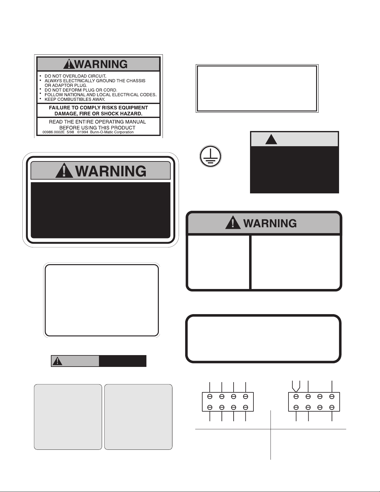
USER NOTICES
TO MACHINE
TO MACHINE
Carefully read and follow all notices on the equipment and in this manual. They were written for your protec-
tion. All notices are to be kept in good condition. Replace any unreadable or damaged labels.
As directed in the International Plumbing Code of the
International Code Council and the Food Code
Manual of the Food and Drug Administration (FDA),
this equipment must be installed with adequate
backflow prevention to comply with federal, state
and local codes. For models installed outside the
U.S.A., you must comply with the applicable Plumbing /Sanitation Code for your area.
00656.0001
00986.0002
To reduce the risk of electric shock,
do not remove or open cover.
No user-serviceable parts inside.
Authorized service personnel only.
Disconnect power before servicing.
37881.0000
Optional Field Wiring
120/208 V, 37.6 A, 7820 W
1PH, 3-Wire + GND, 60HZ
120/240 V, 43.2 A, 10400 W
1PH, 3-Wire + GND, 60HZ
FOR USE ON INDIVIDUAL BRANCH CIRCUIT ONLY
120/208Y V, 32.8 A, 12000 W
3PH, 4-Wire + GND, 60HZ
28181.0004
WARNING: HOT LIQUIDS
37280.0000
! CAUTION
Do not connect to a
circuit operating at
00824.0002
more than 150 volts
to ground.
27508.0000
Moving Parts.
Do not operate
unit with this
panel removed.
Type R134A, Amount 13 oz (368.6 gm)
Design Pressures:
High 276 psi (19 bar) (1.9 MPa)
Low 88 psi (6 bar) (0.61 MPa)
Risk Of Electrical Shock.
Disconnect power before
servicing unit.
27442.0000
CHARGE
33461.0004
REMINDER!
CLEAN AIR FILTER
LIMPIAR EL FILTRO DE
AIRE SEMANALMENTE
WEEKLY
(LOCATED UNDER THE DISPENSER)
RECORDATORIO!
(LOCALIZADO DEBAJO
DEL DISPENSADOR)
CLEAN WEEKLY!
FILTRO DE AIRE
SEMANALMENTE!
40054.0000
AIR FILTER
(LOCATED UNDER THE DISPENSER)
LIMPIAR
(LOCALIZADO DEBAJO
DEL DISPENSADOR)
BLK
L1 L2 L3 N
FROM POWER SOURCE
FOR 3-PHASE OPERATION
CONNECT INPUT WIRING TO
L1,L2,L3 & N AS SHOWN.
RED
BLU
WHI
BLU
BLK
TERMINAL
BLOCK
L1 L2 L3 N
FROM POWER SOURCE
FOR SINGLE PHASE OPERATION
MOVE BLU WIRE INTO
TERMINAL BLOCK WITH BLACK
WIRE, CONNECT INPUT WIRING
TO L1, L2 & N AS SHOWN.
RED
WHI
37947.0002
4
41129.1 080112
ELECTRICAL REQUIREMENTS
TO MACHINE
TO MACHINE
CAUTION: The dispenser must remain disconnected from power source until specified in Electrical Hook-Up.
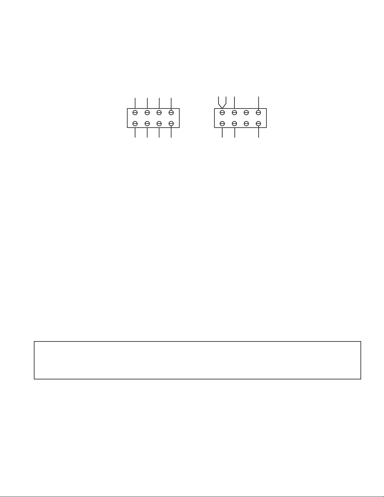
The LCR-3 HV is shipped configured for 3 Phase operation. The internal terminal block must be rewired for
208/240V – 1Phase applications, (see Optional Field Wiring Diagram).
FIELD WIRING TERMINAL BLOCK DIAGRAM
BLU
BLK
L1 L2 L3 N
RED
BLU
WHI
TERMINAL
BLOCK
BLK
RED
L1 L2 L3 N
WHI
FROM POWER SOURCE
Fig 1 Fig 2
FROM POWER SOURCE
For all 208 - 240 Volt Connections: Use No. 6 AWG Wires suitable for 90°C (194 °F)
1. Unit is shipped wired for 3 Phase / 5 wire operation.
2. For 208 - 240V / 1 Phase / 3 Wire: Move the Blue Heater wire to the Top Black Terminal as shown.
3. Unit requires120 Vac from L1 to N.
PLUMBING REQUIREMENTS
The dispenser may be connected to a cold or hot water system (140°F Max.) with operating pressure between
20 and 90 psi (138 and 620 kPa) from a 1/2” or larger supply line. Install a regulator in the line when pressure
is greater than 90 psi (620 kPa) to reduce it to 50 psi (345 kPa). The dispenser is set up to deliver to 6 Oz./sec.
(177.4 ml/sec) and requires a water supply that can deliver a minimum of 3 gpm (11.4 lpm) at the inlet valve. A
shut-off valve should be installed in the line before the dispenser.
NOTE: The water inlet fitting is 3/8” flare. Bunn-O-Matic recommends 3/8” flexible tubing from the 1/2” water
supply line. At least 18 inches of FDA approved beverage tubing, such as reinforced braided polyethylene or
silicone, before the dispenser will facilitate movement to clean the counter top. Bunn-O-Matic does not recommend
the use of a saddle valve to supply water to the dispenser. The size and shape of the hole made in the supply line
made by this type of device may restrict water flow.
NOTE: The water level sensors in this machine do not work with de-ionized water and may cause the unit to overflow.
RO (Reverse Osmosis) water supply systems may need to be treated to restore free ions to the water.
As directed in the International Plumbing Code of the International Code Council and the Food Code
Manual of the Food and Drug Administration (FDA), this equipment must be installed with adequate
backflow prevention to comply with federal, state and local codes. For models installed outside the
U.S.A., you must comply with the applicable Plumbing /Sanitation Code for your area.
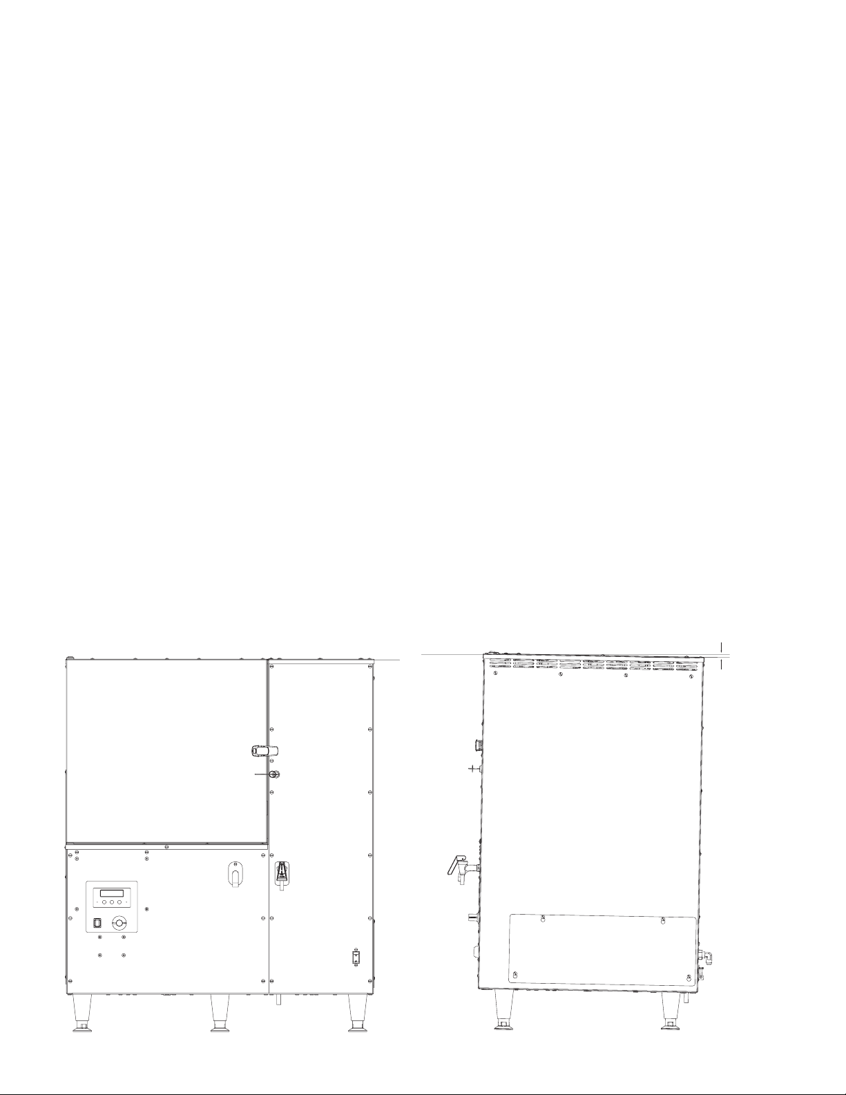
ALTERNATE LOCATION FOR THE WATER AND ELECTRICAL CONNECTIONS
The LCR-3 HV is supplied with the electrical and water connections at the back of the dispenser. However, in
some applications it may be more convenient for one or both of these connections to be located in the bottom
of the dispenser. To change the location, remove appropriate cover plate(s) from the bottom of the dispenser.
Remove the valve and/or electrical clamp and holes plugs from the back of the dispenser and install them in
the bottom panel. Re-install the cover plate on the back of the dispenser to cover the open holes. Take care to
replace and tighten all water clamps, mounting screws and the plastic hole plugs.
5
41129.1 080112
INITIAL SET-UP
NOTE: The LCR-3 HV dispenser weighs approximately 180 lbs. (82 kg). Use more than one person when lifting
or moving the dispenser.
1. Cut the straps and remove the box and foam packing.
2. Locate and remove the information packets and tube kits from top of packaging and set aside.
3. Set dispenser on the counter where it is to be used. CAUTION: DO NOT LIFT ON THE DOOR.
4. Confirm the dispenser is level on the counter (See LEVELING THE DISPENSER).
ELECTRICAL HOOK-UP
CAUTION: Improper electrical installation will damage electronic components.
1. An electrician must provide electrical service as specified in conformance with all local, state and federal
electrical codes.
2. Using a voltmeter, check the voltage and color-coding of each conductor at the electrical source.
3. If plumbing is to be hooked up later, be sure the dispenser is disconnected from the power source. If plumbing
has been hooked up, the dispenser is ready for Initial Fill & Heat.
PLUMBING HOOK-UP
1. Flush the water line to remove any debris or foreign material.
2. Securely attach the water line to the 3/8” flare fitting, lower – right - rear corner of the dispenser.
3. Turn on the water supply and check for leaks.
NOTE - Water pipe connections and fixtures directly connected to a potable water supply shall be sized, installed
and maintained in accordance with federal, state and local codes.
LEVELING THE DISPENSER
Proper leveling of the dispenser is required to insure proper drainage of condensation from the refrigeration unit.
1. Set the dispenser on a level counter top.
2. Use the (6) adjustable legs to level the dispenser.
3. Once the unit is level, adjust the front three legs out another 1/16” to create a slight tilt towards the rear of
the dispenser. (See Fig. below)
LEVEL
1/16"
6
41129.1 080112
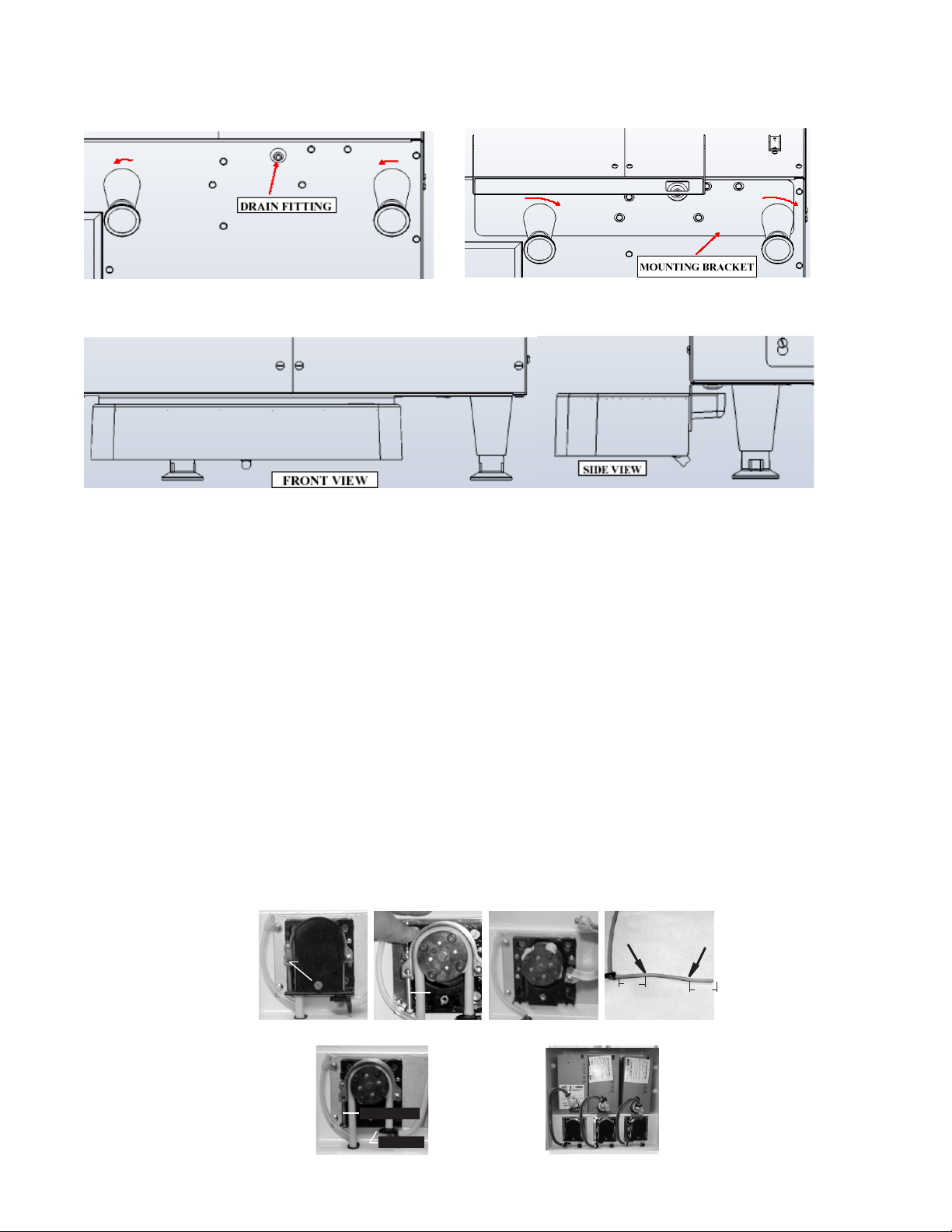
DRIP TRAY INSTALLATION
1. Unscrew the middle and right front legs (Fig. 1) - just enough to allow the mounting bracket to slide under the legs, (~1/8”).
Caution: The LCR-3 HV is very heavy. Use wood blocks to hold the machine up while working underneath it!
2. Insert the bracket between the legs and the base of the machine and retighten the legs, (Fig. 2).
Fig. 1 Fig. 2
3. Insert the Drip Tray onto the mounting bracket, (Fig. 3). Make sure the drain fitting is still protruding through the hole.
Fig. 3
Optional Drip Tray Drain
A separate drain tube (not supplied) may be attached to fitting in the bottom of the tray, if desired. Note: Drill a ¼” hole in the center
of the fitting, before attaching the drain hose. Direct the other end of this hose into a permanent drain.
Alternate Evaporator Drain
For locations where the Drip Tray is not desired, connect a separate drain hose (not supplied) to the Evaporator Drain Fitting and direct
the other end of this hose into a permanent drain.
CAUTION: FAILURE TO INSTALL THE DRIP TRAY OR ALTERNATE EVAPORATOR DRAIN WILL RESULT IN WATER DRIPPING ON TO
THE COUNTER AND/OR FLOOR UNDER THE DISPENSER.
INSTALLING THE PUMP TUBING
(Refer to the Tubing Installation Instructions in side the cabinet door for details.)
1. Loosen the thumbscrew securing the tubing retainer plate to the pump housing. Set the retainer plate aside.
2. Depress the tension screw and remove it from the notch in the pump body, releasing the pump compression band.
3. Apply lubricant (BUNN-O-MATIC part number M2531.0001) to the new pump tubing.
4. Insert the tubing onto the mix chamber port and wrap the tubing around the pump rotor, making sure that the elbow and clamps
end up on the bottom side of the pump body.
5. Close the compression band reinsert the tension screw into the notch in the pump housing.
6. Replace the tubing retainer plate and tighten the thumbscrew.
7. Reconnect bag connector to the product box.
8. Repeat steps 1 through 7 for the other two pumps.
9. Prime the pumps. Refer to Priming the Concentrate Lines section.
Thumbscrew
Tension
Screw
Remove Retaining Plate Release Spring Tension Remove Tubing
Tension Screw
2.0”
Lubricate between arrows
Lubricate New Tube
2.0”
Tube Clamp
Install New Tubing Completed Installation
7
41129.1 080112
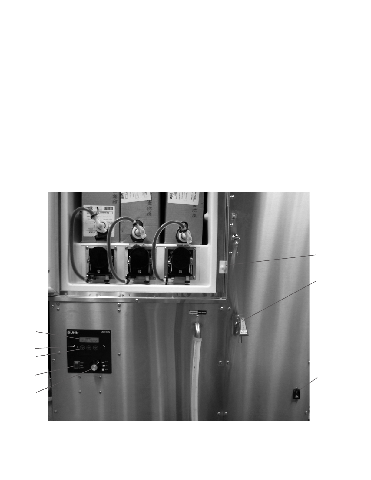
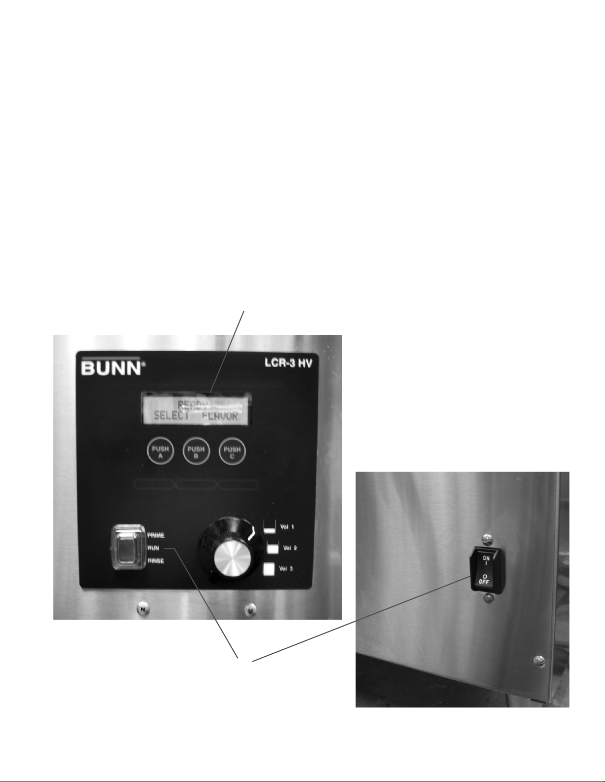
OPERATING CONTROLS AND INTERFACE
1. Master ON/OFF Switch: Disconnects AC Power to the dispenser.
2. Hot Water Handle: Pull and Hold to dispense hot water manually.
3. Door Interlock Switch: Unit will not dispense product if the door is open.
4. LCD Display: Displays status, programming menus and fault messages.
5. Volume Selection: Rotate dial to the desired volume prior to dispensing product.
6. Dispense Switches (A-B-C): Push and Release to dispense the desired product.
(These also double as programming switches in the Set-Up mode).
7. Function Selector Switch: Allows the user to set the dispenser into different dispensing modes.
a. RINSE: Dispenses hot water only - Flushes the mix chamber and dispense tip.
b. RUN: Normal dispense mode - Dispenses mixed product (concentrate and water).
c. PRIME: Dispenses concentrate only – Primes the concentrate pump.
8. Hidden Set-Up / Programming switches.
a. Press and hold the Right switch for 5 sec. to enter in the Set-Up mode.
b. Use the Right switch to scroll down and the Left switch to scroll up through the menu screens.
3
2
4
8
6
7
1
5
8
41129.1 080112
INITIAL FILL & HEAT
1. Confirm the water supply is on.
2. Connect the dispenser to the power source.
3. Turn the Master ON/OFF Switch ON and select RUN on the Function Selector Switch. The LCD will display
“Tank Filling – Please Wait!” and water will begin flowing into the tank.
4. Once the tank is full the dispenser will start heating the water and display “Heating – Select Flavor”. Dispenser
models with product chillers will also begin to cool the cabinet at this time.
5. The LCD will display “Ready Select Flavor” when the tank temperature reaches the preset Ready
Temperature.
Note: The time required to heat the water initially will vary depending on the AC Power and the temperature of
the incoming water. While the tank is heating, the dispenser may be readied for use as described in Programming
Functions & Basic Operations.
4
3
9
41129.1 080112
 Loading...