

Bunn Coffee Maker ICB TWIN Service Manual
RELEASED FOR PRODUCTION
ITB/ITCB/HV
ICB/TWIN
Infusion Series
®
SERVICE & REPAIR MANUAL
BUNN-O-MATIC CORPORATION
POST OFFICE BOX 3227
SPRINGFIELD, ILLINOIS 62708-3227
PHONE: (217) 529-6601 FAX: (217) 529-6644
42461.0000D 05/14 ©2010 Bunn-O-Matic Corporation
DIR Num: 42461.0000 19, May 2015

RELEASED FOR PRODUCTION
BUNN-O-MATIC COMMERCIAL PRODUCT WARRANTY
Bunn-O-Matic Corp. (“BUNN”) warrants equipment manufactured by it as follows:
1) Airpots, thermal carafes, decanters, GPR servers, iced tea/coffee dispensers, MCR/MCP/MCA single cup brewers, thermal servers and ThermoFresh® servers (mechanical and digital) 1 year parts and 1 year labor.
2) All other equipment - 2 years parts and 1 year labor plus added warranties as specified below:
a) Electronic circuit and/or control boards - parts and labor for 3 years.
b) Compressors on refrigeration equipment - 5 years parts and 1 year labor.
c) Grinding burrs on coffee grinding equipment to grind coffee to meet original factory screen sieve analysis - parts and
labor for 4 years or 40,000 pounds of coffee, whichever comes first.
These warranty periods run from the date of installation BUNN warrants that the equipment manufactured by it will be
commercially free of defects in material and workmanship existing at the time of manufacture and appearing within the
applicable warranty period. This warranty does not apply to any equipment, component or part that was not manufactured
by BUNN or that, in BUNN’s judgment, has been affected by misuse, neglect, alteration, improper installation or operation,
improper maintenance or repair, non periodic cleaning and descaling, equipment failures related to poor water quality,
damage or casualty. In addition, the warranty does not apply to replacement of items subject to normal use including but
not limited to user replaceable parts such as seals and gaskets. This warranty is conditioned on the Buyer 1) giving BUNN
prompt notice of any claim to be made under this warranty by telephone at (217) 529-6601 or by writing to Post Office Box
3227, Springfield, Illinois 62708-3227; 2) if requested by BUNN, shipping the defective equipment prepaid to an authorized
BUNN service location; and 3) receiving prior authorization from BUNN that the defective equipment is under warranty.
THE FOREGOING WARRANTY IS EXCLUSIVE AND IS IN LIEU OF ANY OTHER WARRANTY, WRITTEN OR ORAL, EXPRESS OR IMPLIED, INCLUDING, BUT NOT LIMITED TO, ANY IMPLIED WARRANTY OF EITHER MERCHANTABILITY
OR FITNESS FOR A PARTICULAR PURPOSE. The agents, dealers or employees of BUNN are not authorized to make
modifications to this warranty or to make additional warranties that are binding on BUNN. Accordingly, statements by such
individuals, whether oral or written, do not constitute warranties and should not be relied upon.
If BUNN determines in its sole discretion that the equipment does not conform to the warranty, BUNN, at its exclusive option while the equipment is under warranty, shall either 1) provide at no charge replacement parts and/or labor (during the
applicable parts and labor warranty periods specified above) to repair the defective components, provided that this repair
is done by a BUNN Authorized Service Representative; or 2) shall replace the equipment or refund the purchase price for
the equipment.
THE BUYER’S REMEDY AGAINST BUNN FOR THE BREACH OF ANY OBLIGATION ARISING OUT OF THE SALE OF THIS
EQUIPMENT, WHETHER DERIVED FROM WARRANTY OR OTHERWISE, SHALL BE LIMITED, AT BUNN’S SOLE OPTION
AS SPECIFIED HEREIN, TO REPAIR, REPLACEMENT OR REFUND.
In no event shall BUNN be liable for any other damage or loss, including, but not limited to, lost profits, lost sales, loss of
use of equipment, claims of Buyer’s customers, cost of capital, cost of down time, cost of substitute equipment, facilities
or services, or any other special, incidental or consequential damages.
392, A Partner You Can Count On, Air Infusion, AutoPOD, AXIOM, BrewLOGIC, BrewMETER, Brew Better Not Bitter, BrewWISE, BrewWIZARD, BUNN Espress, BUNN Family Gourmet, BUNN Gourmet, BUNN Pour-O-Matic, BUNN, BUNN with
the stylized red line, BUNNlink, Bunn-OMatic, Bunn-O-Matic, BUNNserve, BUNNSERVE with the stylized wrench design,
Cool Froth, DBC, Dr. Brew stylized Dr. design, Dual, Easy Pour, EasyClear, EasyGard, FlavorGard, Gourmet Ice, Gourmet
Juice, High Intensity, iMIX, Infusion Series, Intellisteam, My Café, Phase Brew, PowerLogic, Quality Beverage Equipment
Worldwide, Respect Earth, Respect Earth with the stylized leaf and coffee cherry design, Safety-Fresh, savemycoffee.com,
Scale-Pro, Silver Series, Single, Smart Funnel, Smart Hopper, SmartWAVE, Soft Heat, SplashGard, The Mark of Quality in
Beverage Equipment Worldwide, ThermoFresh, Titan, trifecta, TRIFECTA (sylized logo), Velocity Brew, Air Brew, Beverage
Bar Creator, Beverage Profit Calculator, Brew better, not bitter., Build-A-Drink, BUNNSource, Coffee At Its Best, Cyclonic
Heating System, Daypart, Digital Brewer Control, Element, Milk Texturing Fusion, Nothing Brews Like a BUNN, Picture
Prompted Cleaning, Pouring Profits, Signature Series, Sure Tamp, Tea At Its Best, The Horizontal Red Line, Ultra are either
trademarks or registered trademarks of Bunn-O-Matic Corporation. The commercial trifecta® brewer housing configuration is a trademark of Bunn-O-Matic Corporation.
2
42461 031314
DIR Num: 42461.0000 19, May 2015

RELEASED FOR PRODUCTION
INTRODUCTION
This equipment will brew a half-gallon batch of coffee into an awaiting dispenser. It can be easily
configured for 120V 15 amp, 120/208V 20 amp or 120/240V 20 amp. The brewer may have a hot water
faucet for allied beverage use. It is only for indoor use on a sturdy counter or shelf.
CONTENTS
Warranty .............................................................................................................2
Contents
Troubleshooting
Diagnostic Displays
Access
Control Board
Membrane Switch
Brew Valves (Early)
Brew Valves (Current)
Refill Valves
Tank Heaters
Limit Thermostat
Temperature Probe............................................................................................19
DV Selector Switch
On/Off Switch
Schematic Wiring Diagrams
..............................................................................................................3
..................................................................................................4
.............................................................................................9
..............................................................................................................10
....................................................................................................11
.............................................................................................12
...........................................................................................13
.......................................................................................14
......................................................................................................15
.....................................................................................................17
...............................................................................................18
...........................................................................................21
....................................................................................................22
..............................................................................23
3
DIR Num: 42461.0000 19, May 2015
42461 081310

RELEASED FOR PRODUCTION
TROUBLESHOOTING
A troubleshooting guide is provided to suggest probable causes and remedies for the most likely problems
encountered. If the problem remains after exhausting the troubleshooting steps, contact the Bunn-O-Matic
Technical Service Department.
• Inspection,testing,andrepairofelectricalequipmentshouldbeperformedonlybyqualiedservicepersonnel.
• Allelectroniccomponentshaveaclinevoltageandsomehavelowvoltagedcpotentialontheirterminals.
Shorting of terminals or the application of external voltages may result in board failure.
• Intermittentoperationofelectroniccircuitboardsisunlikely.Boardfailurewillnormallybepermanent.If
an intermittent condition is encountered, the cause will likely be a switch contact or a loose connection at a
terminal or crimp.
• Solenoidremovalrequiresinterruptingthewatersupplytothevalve.Damagemayresultifsolenoidsare
energized for more than ten minutes without a supply of water.
• Theuseoftwowrenchesisrecommendedwheneverplumbingttingsaretightenedorloosened.Thiswill
help to avoid twists and kinks in the tubing.
• Makecertainthatallplumbingconnectionsaresealedandelectricalconnectionstightandisolated.
• Thisbrewerisheatedatalltimes.Keepawayfromcombustibles.
WARNING
• Exerciseextremecautionwhenservicingelectricalequipment.
• Unplugthebrewerwhenservicing,exceptwhenelectricaltestsarespecied.
• Followrecommendedserviceprocedures.
• Replaceallprotectiveshieldsorsafetynotices.
Before troubleshooting this brewer, check for the following:
Control Boards
1. Make sure ribbon cable is properly attached to the control board (ALL PINS INSERTED INTO PLUG).
2. Make sure there is a nylon insulating washer under each screw head that holds the control board to the
plastic front end cap. This is important for proper operation.
3. Make sure before servicing brewer that voltage is present at control board.
4. Press any warmer switch or observe if any indicator lights are glowing on the control panel. If so, proceed
with testing. If not, check for voltage across pins 1 & 2 of the ten pin J1 connector (black and white wires).
If voltage is present, replace the control board. If voltage is not present, check wiring and voltage across
terminal block (black and white). Correct the problem and retest before proceeding with testing.
NOTE: In the event of board replacement, technician will need to re-program customer's settings and/or recipes,
as well as re-calibrate the temperature probe in program level 3 and re-enter the serial number in level 4.
4
DIR Num: 42461.0000 19, May 2015
42461 081310

RELEASED FOR PRODUCTION
TROUBLESHOOTING (cont.)
REFILLCIRCUIT
PROBLEM
Will not refill
PROBABLE CAUSE REMEDY
1. Power off to brewer
Press ENABLE BREW switch on
control panel to determine if power
is ON.
2. Water shut off
3. Error Message
Make sure water is ON.
Brewer has shut down due to malfunction (See Diagnostic Section in
this manual).
4.ON/OFF Switch
(If equipped)
5. Lime build up on Probe(s)
Make sure ON/OFF Switch is "ON"
and indicator is lit.
Remove the Level Probe(s) and
check for lime deposit on tip. Clean
and reinstall.
6. Refill Valve or Control Board
Check valve.
Refill does not shut off
Power "ON"
Refill does not shut off
Power "OFF"
1. Lime build up on probe
2. Water Level Sensing System
3. Refill valve or control board
1. Refill valve
Remove Level Probe and check
for lime deposits on tip. Clean and
reinstall.
Replace control board
Check valve.
Clean or replace valve as needed.
5
DIR Num: 42461.0000 19, May 2015
42461 081310

RELEASED FOR PRODUCTION
TROUBLESHOOTING (cont.)
HEATING CIRCUIT
PROBLEM
Water does not heat to proper
temperature
IMPORTANT: Make sure no temperature tests are taken before
the display reads ready. Tank temperature must be stabilized before
readings are taken.
PROBABLE CAUSE REMEDY
1. Display's error message
Brewer has shut down due to malfunction. See Diagnostics.
2. Water not touching main (short)
level probe
Remove level probe and grommet.
Look into hole on tank lid. Water
must be within approximately one
inch from top of tank.
3. Water Level Probe Sensing
System
Check refill circuit. Heaters will not
turn on if water is not grounding
level probe.
4. Temperature Probe
5. Limit Thermostat or TCO
Check/replace
Check/replace
Spitting or excessive steaming
(cont.)
Brewer is making unusual noises
6. Tank Heater
1. Lime build up on temperature
probe, tank or tank heater
2. Temperature Probe
3. Control Board
1. Plumbing lines
2. Water supply
3. Lime build up
Check/replace
Inspect probe and tank assembly
for excessive lime deposits. Delime
as required.
Check/replace
Check/replace
Plumbing lines should not rest on
the counter top.
The brewer must be connected to
a cold water supply.
Remove the tank lid and clean inside of tank with a deliming agent,
if necessary.
6
DIR Num: 42461.0000 19, May 2015
42461 081310

RELEASED FOR PRODUCTION
TROUBLESHOOTING (cont.)
BREWING CIRCUIT
PROBLEM
Brew cycle will not start
PROBABLE CAUSE REMEDY
1. Display's error message
Brewer has shut down due to malfunction. See Diagnostics.
2. No water
Water lines and valves to the brewer
must be open.
3. No power or incorrect voltage to
the brewer
4. ON/OFF switch not in the "ON"
Check for voltage across the terminals at the terminal block.
The indicator lamp must be lit
position
5. Low water temperature (Brew
lockout is enabled)
Allow brewer to heat until ready, or
disable the brew lockout feature.
Water must be in contact with refill
6. Water not touching refill probe
probe before brew cycle will start.
inside tank
Consistently low beverage level in
the dispenser or beverage overflows
dispenser
7. Membrane Switch
8. Dispense valve
9. Control board
1. Brew volume
NOTE: Volume adjustments must be
made with sprayhead installed.
2. Lime build up
3. Dispense Valve
Check/replace
Check/replace
Check/replace
Inspect the dispense valve and
sprayhead for excessive lime deposits. Delime as required.
Remove dispense valve and clear
any obstructions. Rebuild or replace
valve if necessary. (See page 24)
Check/replace
7
DIR Num: 42461.0000 19, May 2015
42461 081310

RELEASED FOR PRODUCTION
TROUBLESHOOTING (cont.)
BREWING CIRCUIT (cont.)
PROBLEM PROBABLE CAUSE REMEDY
Dripping from sprayhead
Weak beverage
1. Lime build up
2. Dispense valve
1. Sprayhead
2. Water temperature
Inspect the tank assembly for excessive lime deposits. Delime as
required.
Check/replace
A clean sprayhead must be used for
proper extraction.
Place an empty brew funnel on an
empty decanter beneath the sprayhead. Initiate brew cycle and check
the water temperature immediately
below the sprayhead with a thermometer. The reading must not be
less than 195°F (91°C). Adjust the
temperature setting to increase the
water temperature. Refer to Initial
Set-up instructions.
Dry coffee grounds remain in the
funnel
3. Filter type
4. Coffee grind
5. Funnel loading
1. Sprayhead
2. Funnel loading
BUNN® paper filters must be used
for proper extraction.
A fine drip or grind must be used
for proper extraction.
The BUNN® paper filter must be
centered in the funnel and the bed
of grounds leveled by shaking
gently.
Make sure sprayhead is present and
holes are clear and unobstructed.
The BUNN® paper filter must be
centered in the funnel and the bed
of grounds leveled by shaking
gently.
Low beverage serving temperature
DIR Num: 42461.0000 19, May 2015
1. Thermal server/airpot not preheated before brew cycle
8
Preheat server
42461 081310

DIAGNOSTICS
RELEASED FOR PRODUCTION
MESSAGE
Temperature Too Low
Heating Time Too Long
Fill Time Too Long
PROBABLE CAUSE REMEDY
1. Water temperature in the tank
does not meet the ready temperature.
1. Tank Heater failure.
2. Control Board/Thermistor failure
1. Water shut off to brewer
2. Supply line too small or obstructed
3. Inlet Solenoid failure
A) Wait for the brewer to heat to
the proper temperature.
B) Disable the BREW LOCKOUT
function. Refer to programming
section for procedure.
Replace or repair as needed
Replace or repair as needed
Check water supply shut-off
Replace or repair as needed
Replace or repair as needed
Temp Sensor Out Of Range, Check
For Bad Connections
Temp Sensor Out Of Range, Check
Wire For Shorts
4. Control Board Failure
5. ON/OFF switch is OFF
1. Temperature Sensor Probe
open
1. Temperature Sensor Probe
wire(s) shorted
Replace or repair as needed
Turn switch ON
Replace or repair as needed
Replace or repair as needed
9
DIR Num: 42461.0000 19, May 2015
42461 081310
RELEASED FOR PRODUCTION
COMPONENT ACCESS
This section provides procedures for testing and
replacing various major components used in this
brewer should service become necessary. Refer to
Troubleshooting for assistance in determining the
cause of any problem.
WARNING - Inspection, testing, and repair of electrical equipment should be performed only by qualified
service personnel. The brewer should be unplugged
when servicing, except when electrical tests are required and the test procedure specifically states to
plug in the brewer.
WARNING - Disconnect the brewer from the power
source before the removal of any panel or the replacement of any component.
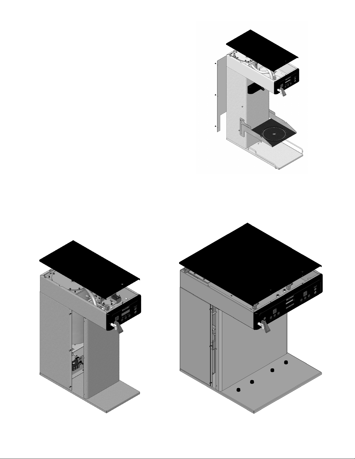
All components are accessible by the removal of
the top cover, front access panel (ICB), or rear access
panel (ITCB & ITB).
Refer to wiring diagrams at the back of this
manual when reconnecting wires.
FIG.10-2ITB/ITCBCOMPONENTACCESS
FIG.10-1ICB/ITCBHV
COMPONENT ACCESS
DIR Num: 42461.0000 19, May 2015
10
FIG.10-3ICB/ITCBHVTWIN
COMPONENT ACCESS
42461 081310
CONTROL BOARD
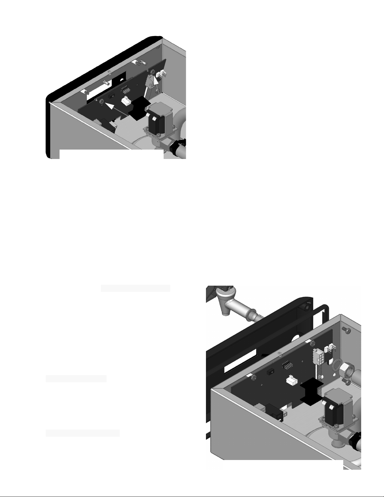
FIG.11-1CONTROLBOARD
RELEASED FOR PRODUCTION
Removal and Replacement:
1. Disconnect brewer from power source.
2. Disconnect the wires from the relay on the control
board.
3. Disconnect all of the connectors from the control
board.
4. Remove the two nuts securing the control board
to the hood.
5. Tilt the control board inward to clear the display
section.
6. Place the bottom edge of the new control board in
the cradle, tilt the board forward, and secure with
the two nuts to the hood.
7. Re-install connectors.
Location:
The Control Board is located inside the top cover
behind the front face plate.
Test Procedures:
The test procedures for the control board will vary
depending upon the problems experienced by the
brewer. Refer to the Troubleshooting section which
is divided into three sections, Refill Circuit, Heating
Circuit, and Brewing Circuit.
Check for Power to board:
1. Insert one meter lead in J17-pin 9 and the other
lead in J17-pin 11 (TR-2 to TR-5 ITB only).
2. With the power connected to brewer, the voltage
reading to the board should be the line voltage
rated for that model.
If no voltage is present, check wiring to the
board. If voltage is present, and brewer does
notpoweron,gotostep3
FaceplateRemovalandReplacement:
1. Disconnect brewer from power source.
2. Disconnect the ribbon cable from the control
board.
3. Models with faucet: Drain tank to below faucet
outlet fitting. Remove hose, nut and washer from
faucet. Remove faucet assembly.
4. Remove the four screws securing the face plate
to the hood.
5. Carefully pull the ribbon cable through the front
opening of the hood.
6. Installation is the reverse order.
3. CheckforlinevoltageatJ15-1BLKtoJ15-2WHI
(J14-1 to 2 ITB only)
If no voltage is present, replace the control
board. If voltage is present, go to step 4
4. Check for 12VAC at J15-4 to J15-2 Yellow wires
(J14-4 to J14-5 ITB only)
If no voltage is present, replace the transformer. If voltage is present, and brewer does
not power on, replace the control board.
DIR Num: 42461.0000 19, May 2015
11
FIG.11-2FACEPLATEREMOVAL
42461 081310
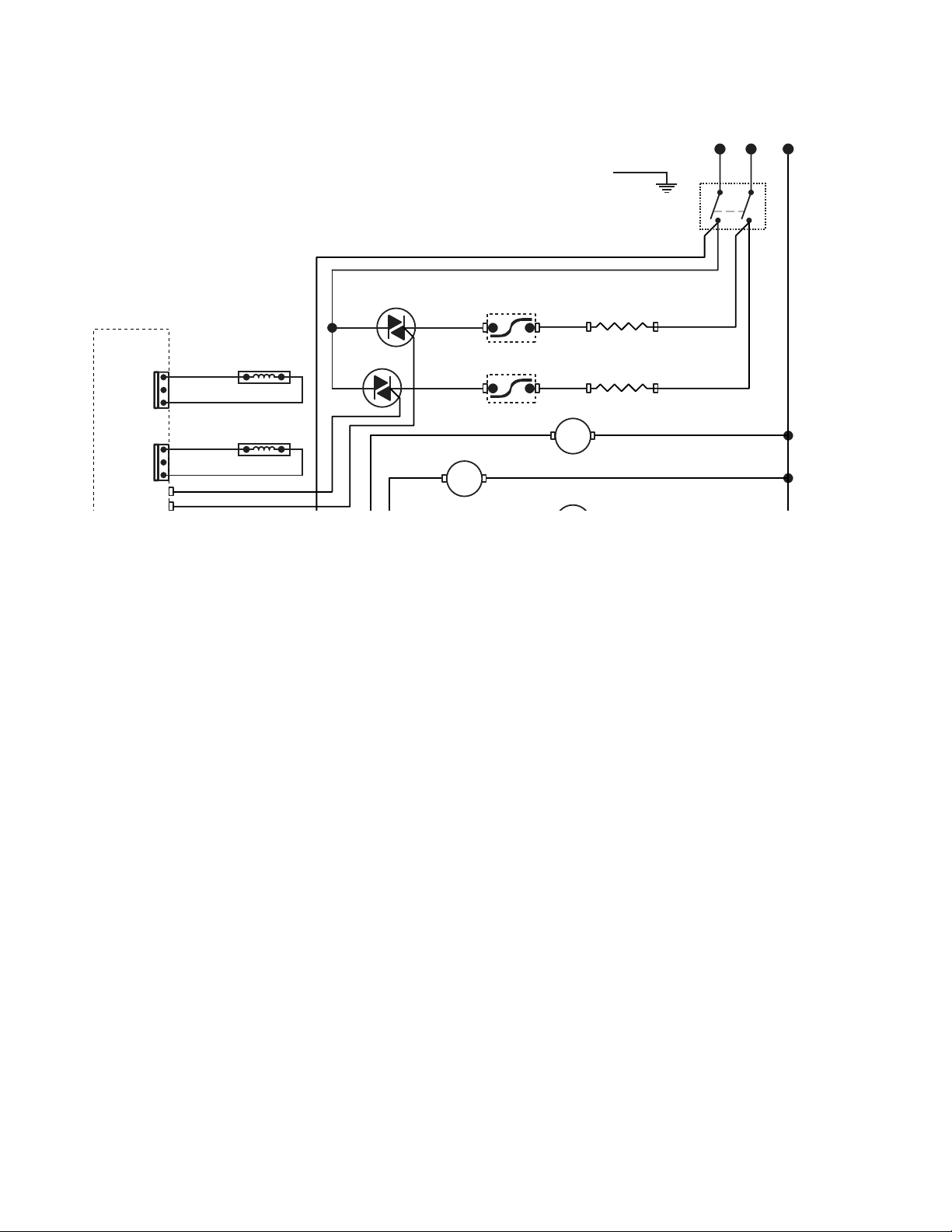
SCHEMATIC WIRING DIAGRAM ICB TWIN
RELEASED FOR PRODUCTION
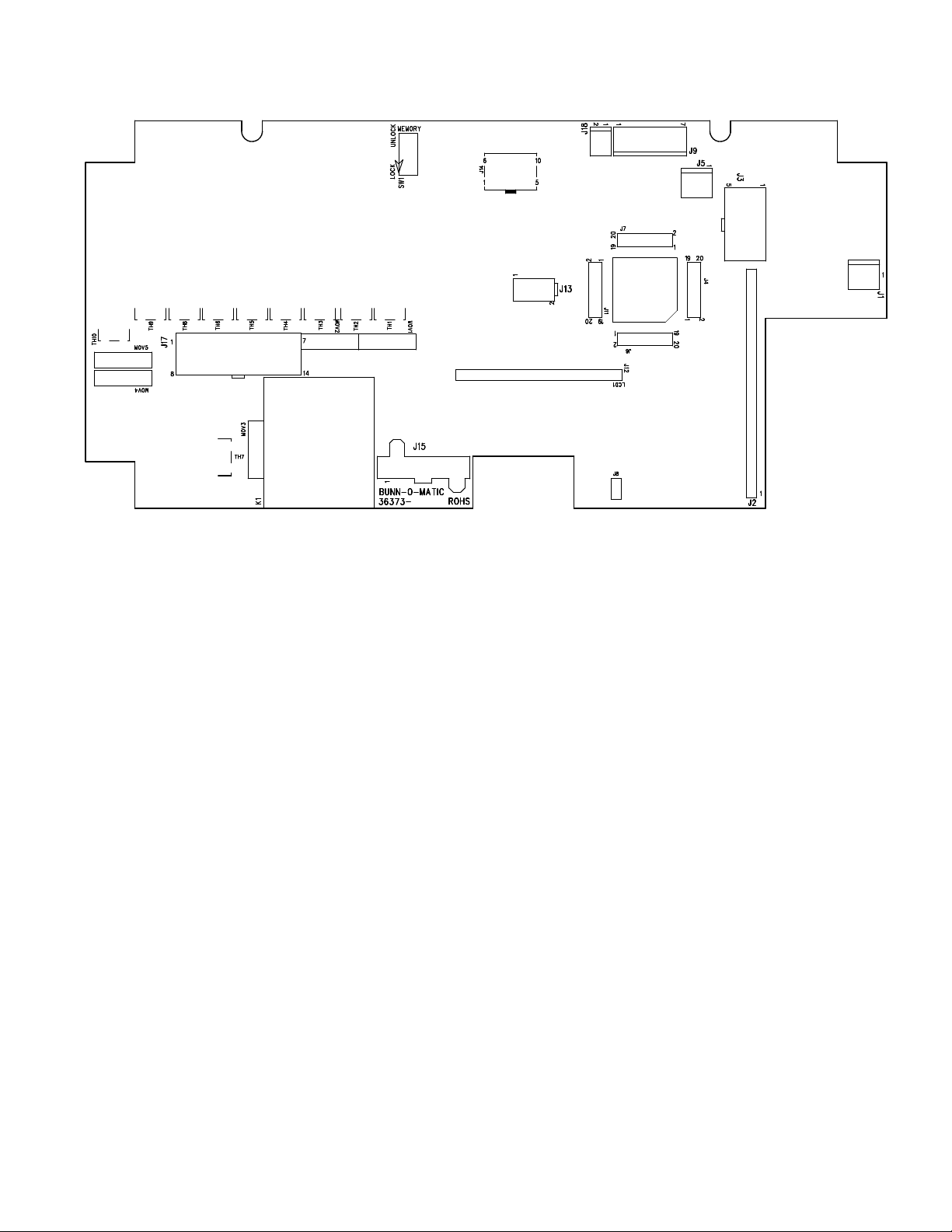
CONTROL BOARD-ICB TWIN/ITCB DV HV/ITCB TWIN HV TRIAC MAP
L2
RED
N
WHI
WHI
WHI
L1
GRN
MAIN ON/OFF SWITCH
(Late Models only)
BLK-18
TRIAC
MT2
LEFT
FUNNEL SENSOR
TR1
VIO
WHI/VIO
YEL
WHI/YEL
TAN
TAN
J20-1
J20-3
J21-1
C
J21-3
O
N
13
RIGHT
FUNNEL SENSOR
13
MT2
TRIAC
MT1
MT1
BLU-14
BLU-14
THERMOSTAT
THERMOSTAT
SOL
LIMIT
LIMIT
RIGHT
DISPENSE
BLU-14
BLU-14
SOL
TANK HEATER
TANK HEATER
LEFT
BYPASS
LEFT
BLK
BLK-14
RED-14
RED-14
FIG. 12-1 TRIAC MAP
Triac: Load Component:
TH1/MOV4/BR2 Left Funnel Lock
TH2/MOV1 Refill solenoid
TH3/MOV3/BR3 Right Funnel Lock
TH4B/MOV2 Tank Heaters
TH5/MOV5 Left Brew Solenoid
TH6/MOV7 Right Brew Solenoid
TH7/MOV8 Left Bypass Solenoid
TH8/MOV6 Right Bypass Solenoid
Connector:
J17-13/J17-14
J17-5
J17-6/J17-7
Relay Terminal
J17-3
J17-2
J17-1
J17-10
12
DIR Num: 42461.0000 19, May 2015
42461 081310
RELEASED FOR PRODUCTION
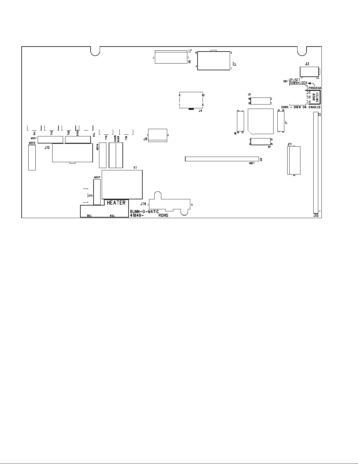
CONTROL BOARD-ICB/ITCB TRIAC MAP
FIG. 13-1 TRIAC MAP
Triac: Load Component:
TH2/MOV1/BR2 (Optional) Funnel Lock (ICB)
TH4B/MOV2 Refill solenoid
TH6/MOV4 Brew Solenoid
TH7/MOV3 Tank Heater(s)
TH9/MOV5 Dilution or Bypass Solenoid
Connector:
J17-13/J17-14
J17-5
J17-3
Relay Terminal
J17-1
13
DIR Num: 42461.0000 19, May 2015
42461 081310
RELEASED FOR PRODUCTION
CONTROL BOARD-ITB TRIAC MAP
FIG. 14-1 TRIAC MAP
Triac: Load Component:
TH1/MOV3 Main or Left Dilution
TH2/MOV1 Refill solenoid
TH3/MOV2 Brew Solenoid
TH4/MOV4 Right Dilution
TH6/MOV6 Sweetner
TH7/MOV7 Tank Heater
Connector:
J10-1
J10-2
J10-3
J10-4
J10-5
TR1/TR6
14
DIR Num: 42461.0000 19, May 2015
42461 081310
 Loading...