

Bunn Coffee Maker ICB Installation Manual
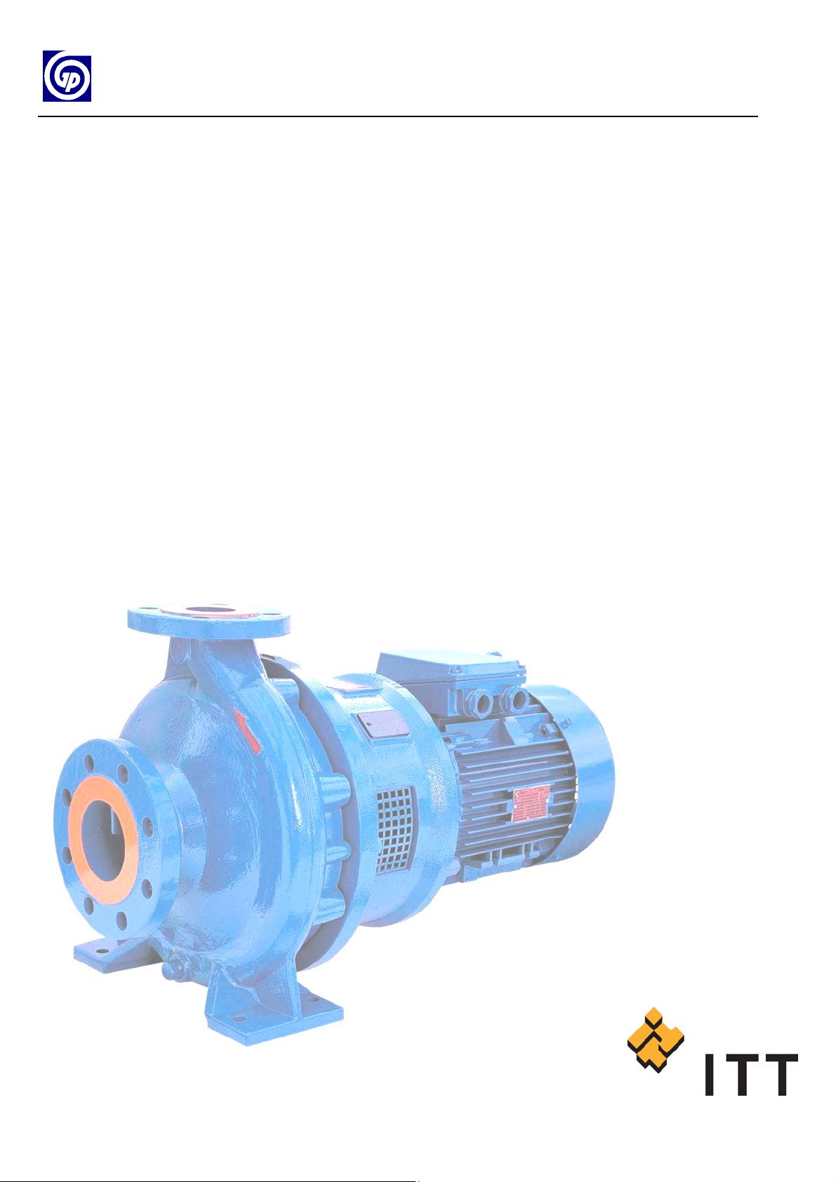
GOULDS PUMPS
Installation, Operation
and
Maintenance Instruction
Volute Casing Pumps
Model:
ICB
ICBI

IMPORTANT SAFETY NOTICE
To: Our Valued Customers
User safety is a major focus in the design of our products. Following the precautions outlined in this
manual will minimize your risk of injury.
ITT Goulds pumps will provide safe, trouble-free service when properly installed, maintained, and
operated.
Safe installation, operation, and maintenance of ITT Goulds Pumps equipment are an essential end user
responsibility. This Pump Safety Manual identifies specific safety risks that must be considered at all
times during product life. Understanding and adhering to these safety warnings is mandatory to ensure
personnel, property, and/or the environment will not be harmed. Adherence to these warnings alone,
however, is not sufficient — it is anticipated that the end user will also comply with industry and corporate
safety standards. Identifying and eliminating unsafe installation, operating and maintenance practices is
the responsibility of all individuals involved in the installation, operation, and maintenance of industrial
equipment.
Please take the time to review and understand the safe installation, operation, and maintenance guidelines
outlined in this Pump Safety Manual and the Instruction, Operation, and Maintenance (IOM) manual.
Current manuals are available at
your nearest Goulds Pumps sales representative.
www.gouldspumps.com/literature_ioms.html or by contacting
These manuals must be read and understood before installation and star t-up.
For additional information, contact your nearest Goulds Pumps sales representative or visit our Web site at
www.gouldspumps.com.
S-1
SAFETY WARNINGS
Specific to pumping equipment, significant risks bear reinforcement above and beyond normal safety precautions.
WARNING
A pump is a pressure vessel with rotating parts that can be hazard o us. An y press ure vessel can explode,
rupture, or discharge its contents if sufficiently ove r press u r i zed causi n g deat h, personal injury, property
damage, and/or damage to the environment. All necessary measures must be taken to ensure over
pressurization does not occur.
WARNING
Operation of any pumping system with a blocked suction and discharge must be avoided in all cases.
Operation, even for a brief period under these conditions, can cause superheating of enclosed pumpage and
result in a violent explosion. All necessary measures must be taken by the end user to ensure this condition is
avoided.
WARNING
The pump may handle hazardous and/or toxic fluids. Care must be taken to identify the contents of the pump
and eliminate the possibility of exposure, particularly if hazardous and/or toxic. Potential hazards include, but
are not limited to, high temperature, flammable, acidic, caustic, explosive, and other risks.
WARNING
Pumping equipment Instruction, Operation, and Maintenance manuals clearly identify accepted methods for
disassembling pumping units. These methods must be adhered to. Specifically, applying heat to impellers
and/or impeller retaining devices to aid in their removal is strictly forbidden. Trapped liquid can rapidly
expand and result in a violent explosion and injury.
ITT Goulds Pumps will not accept responsibility for physical injury, damage, or delays caused by a failure to
observe the instructions for installation, operation, and maintenance contained in this Pump Safety Manual or the
current IOM available at www.gouldspumps.com/literature.
S-2
SAFETY
DEFINITIONS
Throughout this manual the words WARNING, CAUTION, ELECTRICAL, and ATEX are used to indicate
where special operator attention is required.
Observe all Cautions and Warnings highlighted in this Pump Safety Manual and the IOM provided with
your equipment.
WARNING
Indicates a hazardous situation which, if not avoided, could result in death or serious injury.
Example:
Pump shall never be operated without coupling guard installed correctly.
CAUTION
Indicates a hazardous situation which, if not avoi ded, could result in minor or moderate injury.
Example: Throttling flow from the suction side may cause cavitation and pump damage.
ELECTRICAL HAZARD
Indicates the possibility of electrical risks if directions are not followed.
Example: Lock out driver power to prevent electric shock, accidental start-up, and physical injury.
When installed in potentially explosive atmospheres, the instructions that follow the Ex symbol must be
followed. Personal injury and/or equipment damage may occur if these instructions are not followed. If there
is any question regarding these requirements or if the equipment is to be modified, please contact an ITT
Goulds Pumps representative before proceeding.
Example:
parts, resulting in a spark and heat generation.
Improper impeller adjustment could cause contact between the rotating and stationary
S-3
GENERAL PRECAUTIONS
WARNING
A pump is a pressure vessel with rotating parts that can be hazardous. Hazardous fluids may be contained by the
pump including high temperature, flammable, acidic, caustic, explosive, and other risks. Operators and
maintenance personnel must realize this and follow safety measures. Personal injuries will result if procedures
outlined in this manual are not followed. ITT Goulds Pumps will not accept responsibility for physical injury,
damage or delays caused by a failure to observe the instructions in this manual and the IOM provided with your
equipment.
WARNING
WARNING
General Precautions
NEVER use heat to disassemble pump due to risk of explosion from tapped liquid.
NEVER APPLY HEAT TO REMOVE IMPELLER. It may explode due to
trapped liquid.
WARNING
WARNING
WARNING
WARNING
WARNING
WARNING
WARNING
WARNING
WARNING
NEVER operate pump without safety devices installed.
NEVER operate pump without coupling guard correctly installed.
NEVER run pump below recommended minimum flow when dry, or without
prime.
ALWAYS lock out power to the driver befo re per fo rming pump maintenance.
NEVER operate pump with discharge valve closed.
NEVER operate pump with suction valve closed.
DO NOT change service application without approval of an authorized ITT
Goulds Pumps representative.
Safety Apparel:
Insulated work gloves when handling hot bearings or using bearing heater
Heavy work gloves when handling parts with shar p ed ges, especially
impellers
Safety glasses (with side shields) for eye protection
Steel-toed shoes for foot protection when handling parts, heavy tools, etc.
Other personal protective equipment to protect against hazardous/toxic fluids
Receiving:
Assembled pumping units and their components are heavy. Failure to properly lift
and support equipment can result in serious physical injury and/or equipment
damage. Lift equipment only at specifically identified lifting points or as
instructed in the current IOM. Current manuals are available at
www.gouldspumps.com/literature_ioms.html or from your local ITT Goulds
Pumps sales representative. Note: Lifting devices (eyebolts, slings, spreaders, etc.)
must be rated, selected, and used for the entire load being lifted.
Alignment:
WARNING
Shaft alignment procedures must be followed to prevent catastrophic failure of
drive components or unintended contact of rotating parts. Follow coupling
manufacturer’s coupling installation and operation procedures.
S-4

WARNING
CAUTION
General Precautions
Before beginning any alignment procedure, make sure driver power is locked out.
Failure to lock out driver power will result in serious physical injury.
Piping:
Never draw piping into place by forcing at the flan ged con necti on s of t he pump.
This may impose dangerous strains on the unit and cause misalignment between
pump and driver. Pipe strain will adversely effect the operation of the pump
resulting in physical injury and damage to the equipment.
WARNING
WARNING
WARNING
WARNING
WARNING
WARNING
WARNING
WARNING
WARNING
WARNING
WARNING
CAUTION
CAUTION
WARNING
Flanged Connections:
Use only fasteners of the proper size and material.
Replace all corroded fasteners.
Ensure all fasteners are properly tightened and there are no missing fasteners.
Startup and Operation:
When installing in a potentially explosive environment, please ensure that the
motor is properly certified.
Operating pump in reverse rotation may result in contact of metal parts, heat
generation, and breach of containment.
Lock out driver power to prevent accidental start-up and physical injury.
The impeller clearance setting procedure must be followed. Improperly setting
the clearance or not following any of the proper procedures can result in sparks,
unexpected heat generation and equipment damage.
If using a cartridge mechanical seal, the centering clips must be installed and set
screws loosened prior to setting impeller clearance. Failure to do so could result
in sparks, heat generation, and mechanical seal damage.
The coupling used in an ATEX classified environment must be properly certified
and must be constructed from a non-sparking material.
Never operate a pump without coupling guard properly installed. Personal injury
will occur if pump is run without coupling guard.
Make sure to properly lubricate the bearings. Failure to do so may result in excess
heat generation, sparks, and / or premature failure.
The mechanical seal used in an ATEX classified environment must be properly
certified. Prior to start up, ensure all points of potential leakage of process fluid to
the work environment are closed.
Never operate the pump without liquid supplied to mechanical seal. Running a
mechanical seal dry, even for a few seconds, can cause seal damage and must be
avoided. Physical injury can occur if mechanical seal fails.
Never attempt to replace packing until the driver is properly locked out and the
coupling spacer is removed.
WARNING
WARNING
S-5
Dynamic seals are not allowed in an ATEX classified environment.
DO NOT operate pump below minimum rated flows or with suction and/or
discharge valve closed. These conditions may create an explosive hazard due to
vaporization of pumpage and can quickly lead to pump failure and physical injury.
WARNING
WARNING
WARNING
WARNING
WARNING
CAUTION
CAUTION
WARNING
CAUTION
CAUTION
General Precautions
Ensure pump is isolated from system and pressure is relieved before
disassembling pump, removing plu gs, ope ni n g vent or drain valves, or
disconnecting piping.
Shutdown, Disassembly, and Reassembly:
Pump components can be heavy. Proper methods of lifting must be employed to
avoid physical injury and/or equipment damage. Steel toed shoes must be worn at
all times.
The pump may handle hazardous and/or toxic fluids. Observe proper
decontamination procedures. Proper personal protective equipment should be
worn. Precautions must be taken to prevent physical injury. Pumpage must be
handled and disposed of in conformance with applicable environmental
regulations.
Operator must be aware of pumpage and safety precautions to prevent physical
injury.
Lock out driver power to prevent accidental startup and physical injury.
Allow all system and pump components to cool before handling them to prevent
physical injury.
If pump is a Model NM3171, NM3196, 3198, 3298, V3298, SP3298, 4150, 4550,
or 3107, there may be a risk of static electric discharge from plastic parts that are
not properly grounded. If pumped fluid is non-conductive, pump should be
drained and flushed with a conductive fluid under conditions that will not allow
for a spark to be released to the atmosphere.
Never apply heat to remove an impeller. The use of heat may cause an explosion
due to trapped fluid, resulting in severe physical injury and property damage.
Wear heavy work gloves when handling impellers as sharp edges may cause
physical injury.
Wear insulated gloves when using a bearing heater. Bearings will get hot and can
cause physical injury.
S-6
ATEX CONSIDERATIONS and INTENDED USE
Special care must be taken in potentially explosive environments to ensure that the equipment is properly
maintained. This includes but is not limited to:
1. Monitoring the pump frame and liquid end temperature.
2. Maintaining proper bearing lubrication.
3. Ensuring that the pump is operated in the intended hydraulic range.
The ATEX conformance is only applicable when the pump unit is operated within its intended use. Operating,
installing or maintaining the pump unit in any way that is not covered in the Instruction, Operation, and
Maintenance manual (IOM) can cause serious personal injury or damage to the equipment. This includes any
modification to the equipment or use of parts not provided by ITT Goulds Pumps. If there is any question
regarding the intended use of the equipment, please contact an ITT Goulds represe ntative before proceeding.
Current IOMs are available at
Pumps Sales representative.
All pumping unit (pump, seal, coupling, motor and pump accessories) certified for use in an ATEX classified
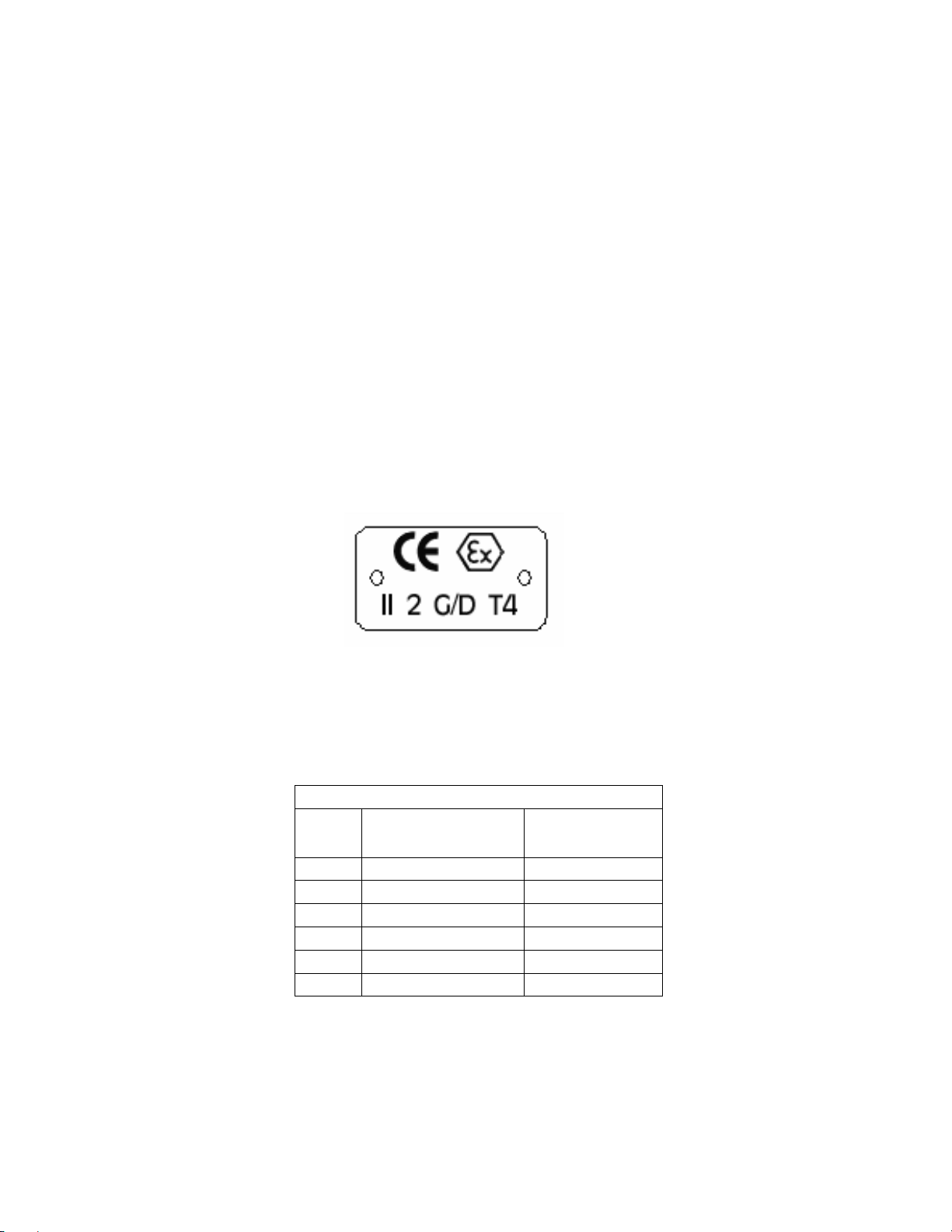
environment, are identified by an ATEX tag secured to the pump or the baseplate on which it is mounted. A
typical tag would look like this:
www.gouldspumps.com/literature_ioms.html or from your local ITT Goulds
The CE and the Ex designate the ATEX compliance. The code directly below these symbols reads as follows:
II = Group 2
2 = Category 2
G/D = Gas and Dust present
T4 = Temperature class, can be T1 to T6 (see Table 1)
Table 1
Max permissible
surface temperature
Code
T1 842 (450) 700 (372)
T2 572 (300) 530 (277)
T3 392 (200) 350 (177)
T4 275 (135) 235 (113)
T5 212 (100) Option not available
T6 185 (85) Option not available
o
F (oC)
The code classification marked on the equipment must be in accordance with the specified area where the
equipment will be installed. If it is not, do not operate the equipment and contact your ITT Goulds Pumps sales
representative before proceeding.
Max permissible
liquid temperature
o
F (oC)
S-7
PARTS
The use of genuine Goulds parts will provide the safest and
most reliable operation of your pump. ITT Goulds Pumps ISO
certification and quality control procedures ensure the parts are
manufactured to the highest quality and safety levels.
Please contact your local Goulds representative for details on
genuine Goulds parts.
S-8

Installation, Operation and Maintenance Instruction
TABLE of CONTENTS
Pump Name Plate .....................................................2
ATEX-Label (only for pumps in compliance with
EC directive 94/9/EC)................................................ 2
1. General ..................................................................3
1.1 Guarantee.........................................................3
2. Safety Regulations ............................................... 3
2.1 Marking of References in the Operating
Instructions..............................................................3
2.2 Dangers of non-observance of the Safety
Instructions..............................................................4
2.3 Safety Instructions for the Operator / Worker...4
2.4 Safety Instructions for Maintenance, Inspections
and Mounting Work.................................................4
2.5 Unauthorized Alteration and Spare Parts
Production............................................................... 4
2.6 Undue Operation............................................... 4
2.7 Explosion Protection......................................... 4
2.8 Use acc. to Regulations.................................... 6
3. Description............................................................ 6
3.1 Design............................................................... 6
3.1.1 Design Coding System ..................................6
3.2 Shaft Sealing..................................................... 7
3.3 Bearing..............................................................7
3.4 Approximate Value for Sound Pressure Level.. 7
3.5 Permitted Nozzle Loads and Torques at the
Pump Nozzles ........................................................ 7
3.6 Permitted pressures and temperatures ............ 8
3.7 Condensate....................................................... 9
4. Transport, Handling, Storage.............................. 9
4.1 Transport, Handling ..........................................9
4.2 Storage / Conservation.....................................9
5. Mounting / Installation ......................................... 9
5.1 Mounting of Pump / Unit ...................................9
5.2 Connection of Pipings to the Pump ................10
5.3 Drive................................................................10
5.4 Electric Connection.........................................10
5.5 Final Control.................................................... 11
6. Start-up, Operation, Shut down ........................11
ICB 100-English page 1
Article No 21999991
6.1 Initial start-up...................................................11
6.2 Switch on drive................................................11
6.3 Restarting........................................................11
6.4 Limits of Operation ..........................................11
6.5 Lubrication.......................................................12
6.6 Monitoring........................................................12
6.7 Shutting down..................................................12
6.8 Storage / longer periods of non-operation.......12
7. Servicing, Maintenance......................................13
7.1 General remarks..............................................13
7.2 Mechanical seals.............................................13
7.3 Motor bearings ................................................13
7.4 Cleaning of pump ............................................13
8. Dismantling and repair of pump........................13
8.1 General remarks..............................................13
8.2 General............................................................13
8.3 Removal and Installation of screen in the motor
lantern....................................................................13
8.4 Removal of the Back Pull Out Assembly.........14
8.5 Removal of Impeller ........................................14
8.6 Removal of Shaft Sealing................................14
8.7 Removal of Stub Shaft ....................................14
8.8 Reconditioning.................................................15
8.9 Mounting..........................................................15
9. Spare parts, Spare pumps .................................16
9.1 Spare parts......................................................16
9.2 Stand-by pumps ..............................................16
10. Faults - Causes and Solutions.........................17
Appendix
Installation Manual - Single mech. seal without shaft
sleeve (Design code S1..2).......................................19
Installation Manual - Single mech. seal with quench
without shaft sleeve (Design code S4..2) ………......
20
Sectional drawing pump unit (Design code S1..2),
Impeller with back vanes.......................................... 23
Sectional drawing pump unit (Design code S1..2),
Impeller with balancing holes................................... 24
Sectional drawing pump unit (Design code S4..2),
Impeller with back vanes.......................................... 25
Sectional drawing pump unit (Design code S4..2),
Impeller with balancing holes................................... 26
Connections............................................................. 27
Dimensional drawing................................................ 28
Model ICB
Revision 00
Issue 05/2006
Installation, Operation and Maintenance Instruction
Pump Name Plate
Model ICB
TYPE *) Type and size of pump
S/N *) Serial number
YEAR Year of construction
Q Rated capacity at the operating point
P Rated power at the operating point
H Head (Energy head) at the operating point
N Speed
P
Max. permitted casing-operation-pressure
all w C
(=highest discharge pressure at the rated
operating temperature to which the pump
casing can be used).
TEMP Rated operating temperature of pumped
liquid
ITEM NO Customer equipment number
*) All details of design and materials are defined with
this information. They must be stated on all inquiries
to the manufacturer resp. orders of spare.
MATL Material of construction
ATEX-Label (only for pumps in compliance with EC directive 94/9/EC)
CE Marking of compliance with the EC directive
94/9/EC
Ex specific marking for explosion protection
II Symbol for the appliance group
2G Symbol for the category (2), explosive
atmosphere due to gases, vapors or mist (G)
c Symbol for used ignition protection
(constructual safety "c")
T1-T. Symbol for classification of the theoretically
available range of the temperature classes -
data for temperature class refer to chapter
2.7.5; Data for maximum permitted
temperature of pumped liquid refer to pump
name plate, data sheet and / or order
confirmation.
ICB 100-English page 2
Article No 21999991
The conformity with the EC directive 94/9/EC "
Equipment and Protective Systems for Use in
Potentially Explosive Atmospheres " is declared by
the issue of the EC-Declaration of Conformity and the
attachment of the ATEX-label at the pump (adapter).
The ATEX-label is attached additionally to the pump
name plate.
Revision 00
Issue 05/2006
Installation, Operation and Maintenance Instruction
f
1. General
Model ICB
This product corresponds with the requirements of the
Machine directive 98/37/EG (former 89/392/EWG).
The staff employed on installation, operation,
inspection and maintenance must be able to
prove that they know about the relevant
accident prevention regulations and that they
are suitably qualified for this work. If the staf
does not have the relevant knowledge, they
should be provided with suitable instruction.
The operation safety of the delivered pump resp. unit
(= pump with motor) can only be guaranteed on
designated use according to the attached data sheet
and / or order confirmation resp. chapter 6 "Start-up,
Operation, Shut down".
The operator is responsible for following the
instructions and complying with the safety
requirements given in these Operating Instructions.
Smooth operation of the pump or pump unit can only
be achieved if installation and maintenance are
carried out carefully in accordance with the rules
generally applied in the field of engineering and
electrical engineering.
If not all the information can be found in these
Operating Instructions, please contact us.
The manufacturer takes no responsibility for the pump
or pump unit if the Operating Instructions are not
followed.
These Operating Instructions should be kept in a safe
place for future use.
If this pump or pump unit is handed on to any third
party, it is essential that these Operating Instructions
and the operating conditions and working limits given
in the Confirmation of Order are also passed on in full.
These Operating Instructions do not take into account
all design details and variants nor all the possible
chance occurrences and events which might happen
during installation, operation and maintenance.
We retain all copyright in these Operating Instructions;
they are intended only for personal use by the owner
of the pump or the pump unit. The Operating
Instructions contain technical instructions and
drawings which may not, as a whole or in part, be
reproduced, distributed or used in any unauthorised
way for competitive purposes or passed on to others.
1.1 Guarantee
The guarantee is given in accordance with our
Conditions of Delivery and / or the confirmation of
order.
Repair work during the guarantee period may only be
carried out by us, or subject to our written approval.
Otherwise the guarantee ceases to apply.
Longer-term guarantees basically only cover correct
handling and use of the specified material. The
guarantee shall not cover natural wear and tear and
all parts subject to wear, such as impellers, shaft
sealings, shafts, shaft sleeves, bearings, wear rings
etc. or damage caused by transport or improper
handling.
In order for the guarantee to apply, it is essential that
the pump or pump unit is used in accordance with the
operating conditions given on the name plate,
confirmation of order and in the data sheet. This
applies particularly for the endurance of the materials
and smooth running of the pump and shaft sealing.
If one or more aspects of the actual operating
conditions are different, we should be asked to
confirm in writing that the pump is suitable.
2. Safety Regulations
These Operating Instructions contain important
instructions which must be followed when the pump is
assembled and commissioned and during operating
and maintenance. For this reason, these Operating
Instructions must be read by the skilled staff
responsible and / or by the operator of the plant
before it is installed and commissioned, and they must
be left permanently available at the place where the
pump or pump unit is in use.
These Operating Instructions do not refer to the
General Regulations on Accident Prevention or
local safety and / or operating regulations. The
operator is responsible for complying with these
(if necessary by calling in additional installation
staff).
Equally, instructions and safety devices regarding
handling and disposal of the pumped media and/or
auxilliary media for flushing, lubrication a.s.o.,
especially if they are explosive, toxical, hot a.s.o., are
not part of this operating instruction.
ICB 100-English page 3
Article No 21999991
For the competent and prescribed handling only the
operator is responsible.
2.1 Marking of References in the
Operating Instructions
The safety regulations contained in these Operating
Instructions are specially marked with safety signs acc.
to nach DIN 4844:
Safety reference!
Non-observance can impair the pump and its
function.
EC-Ex Marking
Products intended for use in explosive
atmospheres must be marked.
General Symbol for Danger!
Persons can be endangered.
Warning of electric voltage!
Revision 00
Issue 05/2006

Installation, Operation and Maintenance Instruction
Safety instructions attached directly to the pump resp.
unit must be followed under any circumstances.
Further they must be kept in good readable condition.
In the same way, as these Operating Instructions
of the pump, all possibly attached Operating
Instructions of accessories (e.g. motor) must be
noticed and kept available.
2.2 Dangers of non-observance of the
Safety Instructions
Non-observance of the Safety Instructions can
lead to loss of any claim for damages.
Further, non-observance can lead to following risks:
Failure of important functions of the machine or
facility.
Failure of electronic appliances and measuring
instruments by magnetic fields.
Endangering of persons and their personal
property by magnetic fields.
Endangering of persons by electric, mechanic and
chemical influences.
Endangering of environment through leakage of
dangerous substances.
On application of the unit in areas endangered
to explosion special attention must be paid to
sections marked with Ex.
2.3 Safety Instructions for the Operator /
Worker
Depending on the operating conditions, wear and
tear, corrosion or age will limit the working life of
the pump/pump unit, and its specified
characteristics. The operator must ensure that
regular inspection and maintenance are carried
out so that all parts are replaced in good time,
which would otherwise endanger the safe
operation of the system. If abnormal operation or
any damage are observed, the pump must cease
operation immediately.
If the breakdown or failure of any system or unit
could lead to people being hurt or property being
damaged, such system or unit must be provided
with alarm devices and/or spare modules, and
they should be tested regularly to ensure that they
function properly.
If there is any risk of injury from hot or cold
machine parts, these parts must be protected
against contact by the user, or suitable warning
signs must be affixed.
Contact protection on moving parts (e.g. coupling
guards) must not be removed from systems that
are in operation.
If the sound level of a pump or pump unit is above
85 dB(A) an ear protection has to be used when
staying near the pump for some time.
If dangerous media (e.g. explosive, toxic, hot)
leak out (e.g. from shaft seals), these must be
directed away so that there is no danger to people
or the environment. The provisions of the law
must be observed.
ICB 100-English page 4
Article No 21999991
Measures should be taken to exclude any danger
from electricity (e.g. by complying with the local
regulations on electrical equipment). If work is
carried out on live electrical components, they
should be unplugged from the mains or the main
switch turned off and fuse unscrewed. A motor
protection switch is to be provided.
Model ICB
2.4 Safety Instructions for Maintenance,
Inspections and Mounting Work
The operator is responsible that any maintenance,
inspections and mounting work is made by
authorized competent personnel, which must be
informed by having read the Operating
Instructions.
Basically, all work on the pump or pump unit
should only be carried out when the pump is
stationary and not under pressure. All parts must
be allowed to return to ambient temperature.
Make sure that no-one can start the motor during
such work. It is essential that the procedure for
stopping the system described in the Operating
Instructions is observed. Pumps or pump systems
that carry media that are dangerous to health
must be decontaminated before being taken apart.
Safety Data Sheets for the various liquids handled.
Immediately after finishing work, all safety and
protective devices must be replaced or restarted.
2.5 Unauthorized Alteration and Spare
Parts Production
Alteration or changes of the machine are permitted
after agreement with the manufacturer.
Original spare parts and accessory authorized by the
manufacturer are serving the safety.
The use of other parts can lead to loss of liability for
therefrom resulting consequences.
2.6 Undue Operation
The operating safety of the delivered machine can
only be guaranteed by designated use acc. to the
following chapters of the Operating Instructions.
The limits stated in the data sheet and / or order
confirmation must not be exceeded under any
circumstances.
2.7 Explosion Protection
On application of units in areas endangered to
explosion measures and references in the chapters
2.7.1 to 2.7.6 must be observed, so that explosion
protection is guaranteed.
2.7.1 Filling of unit
Revision 00
Issue 05/2006
 Loading...