

Page 1
VPR TC
VPR APS
OPERATING & SERVICE MANUAL
BUNN-O-MATIC CORPORATION OF CANADA
280 INDUSTRIAL PARKWAY SOUTH,
AURORA, ONTARIO, L4G 3T9
PHONE: (905) 841-2866 FAX: (905) 841-2775
39064.7000A 05/09 ©2006 Bunn-O-Matic Corporation www.bunn.com
Page 2

INTRODUCTION
This equipment will brew a half-gallon batch of coffee into an awaiting dispenser. It is only for
indoor use on a sturdy counter or shelf.
BUNN-O-MATIC COMMERCIAL PRODUCT WARRANTY
Bunn-O-Matic Corporation of Canada (“Bunn”) warrants equipment manufactured by it as follows:
1) Airpots, thermal carafes, decanters, GPR servers, iced tea/coffee dispensers, MCP/MCA pod brewers
thermal servers and Thermofresh servers (mechanical and digital) - 1 year parts and 1 year labour.
2) All other equipment - 2 years parts and 1 year labour plus added warranties as specified below:
a) Electronic circuit and/or control boards - parts and labour for 3 years.
b) Compressors on refrigeration equipment - 5 years parts and 1 year labour.
c) Grinding burrs on coffee grinding equipment to grind coffee to meet original factory screen sieve
analysis - parts and labour for 4 years or 40,000 pounds of coffee, whichever comes first.
These warranty periods run from the date of installation. Bunn warrants that the equipment manufactured
by it will be commercially free of defects in material and workmanship existing at the time of manufacture and
appearing within the applicable warranty period. This warranty does not apply to any equipment, component
or part that was not manufactured by Bunn or that, in Bunn’s judgement, has been affected by misuse, neglect,
alteration, improper installation or operation, improper maintenance or repair, non periodic cleaning and descaling,
equipment failures related to poor water quality, damage or casualty. In addition, the warranty does not apply to
replacement of items subject to normal use including but not limited to user replaceable parts such as seals and
gaskets. This warranty is conditioned on the Buyer 1) giving Bunn prompt notice of any claim to be made under
this warranty by telephone at (905) 841-2866 or by writing to 280 Industrial Parkway South, Aurora, Ontario, L4G
3T9. 2) if requested by Bunn, shipping the defective equipment prepaid to an authorized Bunn service location;
and 3) receiving prior authorization from Bunn that the defective equipment is under warranty.
THE FOREGOING WARRANTY IS EXCLUSIVE AND IS IN LIEU OF ANY OTHER WARRANTY, CONDITION,
WRITTEN OR ORAL, EXPRESS OR IMPLIED, INCLUDING, BUT NOT LIMITED TO, ANY IMPLIED WARRANTY
OF EITHER MERCHANTABILITY, MERCHANTABLE QUALITY OR FITNESS FOR A PARTICULAR PURPOSE.The
agents, dealers or employees of Bunn are not authorized to make modifications to this warranty or to make
additional warranties that are binding on Bunn. Accordingly, statements by such individuals, whether oral or
written, do not constitute warranties and should not be relied upon.
If Bunn determines in its sole discretion that the defective equipment is covered by warranty, Bunn, at its
exclusive option while the equipment is under warranty, shall either 1) provide at no charge replacement parts
and/or labour (during the applicable parts and labour warranty periods specified above) to repair the defective
components, provided that this repair is done by a Bunn Authorized Service Representative; or 2) shall replace
the equipment or refund the purchase price for the equipment.
THE BUYER’S REMEDY AGAINST BUNN FOR THE BREACH OF ANY OBLIGATION ARISING OUT OF THE
SALE OF THIS EQUIPMENT, WHETHER DERIVED FROM WARRANTY OR OTHERWISE, SHALL BE LIMITED, AT
BUNN’S SOLE OPTION AS SPECIFIED HEREIN, TO REPAIR, REPLACEMENT OR REFUND.
In no event shall Bunn be liable for any other damage or loss, including, but not limited to, lost profits, lost
sales, loss of use of equipment, claims of Buyer’s customers, cost of capital, cost of down time, cost of substitute
equipment, facilities or services, or any other special, incidental, consequential or punitive damages.
RETURN POLICY
CONTACT PLANT FOR RETURN MATERIAL AUTHORIZATION. ALL RETURNS MUST
BE AUTHORIZED BY BUNN-O-MATIC AND ARE SUBJECT TO A RETURN CHARGE.
Page 2
39064 042806
Page 3
USER NOTICES
PN: 00658.7000G 02/10 © 1985 BUNN-O-MATIC CORPORATION OF CANADA
READ THE ENTIRE OPERATING MANUAL BEFORE USING THIS PRODUCT.
FAILURE TO COMPLY RISKS INJURY.
VEUILLEZ LIRE LE MANUEL D’EMPLOI AVANT D’UTILISER CE PRODUIT.
L’INOBSERVATION DE CES CONSEILS PEUT ENTRAÎNER DES RISQUES DE BLESSURE.
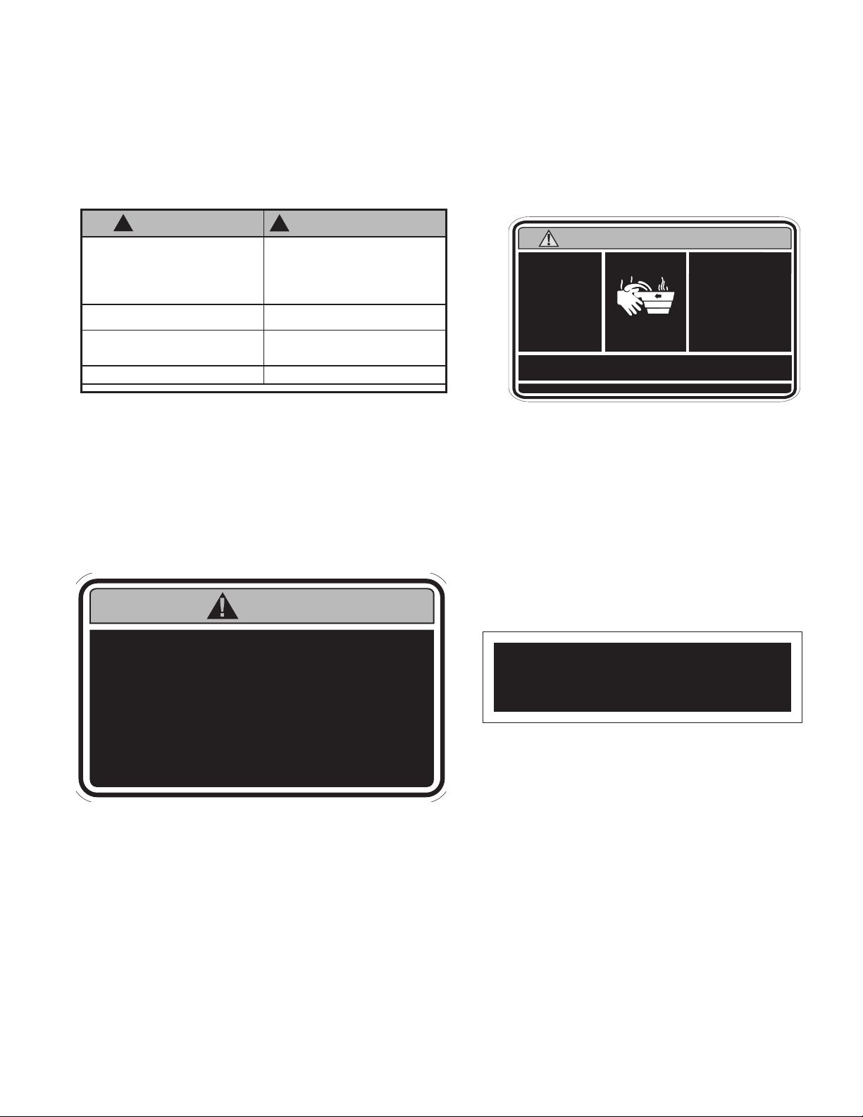
LE CONTENU
DE L’ENTONNOIR
EST CHAUD
FUNNEL CONTENTS
ARE HOT
DISCARD DECANTER
IF:
• CRACKED
• SCRATCHED
• BOILED DRY
• HEATED WHEN EMPTY
•
USED ON HIGH FLAME
OR EXPOSED ELECTRIC
ELEMENTS
JETER LA CARAFE :
• SI ELLE EST FISSURÉE
• SI ELLE EST RAYÉE
• SI ON A LAISSÉ DE L’EAU
S’ÉVAPORER PAR
ÉBULLITION
• SI ELLE A ÉTÉ CHAUFFÉE À VIDE
•
SI ELLE A ÉTÉ UTILISÉE SUR
UNE FLAMME VIVE OU SUR
DES ÉLÉMENTS ÉLECTRIQUES
DÉCOUVERTS
WARNING / AVERTISSEMENT
Carefully read and follow all notices in this manual and on the equipment. All labels on the equipment should
be kept in good condition. Replace any unreadable or damaged labels.
! WARNING
• FILL WATER TANK BEFORE PLUGGING IN UNIT OR
ENERGIZING THE THERMOSTAT.
• DO NOT OVERLOAD CIRCUIT.
• ALWAYS ELECTRICALLY GROUND THE CHASSIS.
• DO NOT DEFORM PLUG OR CORD.
• FOLLOW NATIONAL AND LOCAL ELECTRICAL CODES.
• KEEP COMBUSTIBLES AWAY.
FAILURE TO COMPLY RISKS EQUIPMENT DAMAGE, FIRE OR
SHOCK HAZARD.
READ THE ENTIRE OPERATING MANUAL INCLUDING
THE LIMIT OF WARRANTY AND LIABILITY BEFORE
BUYING OR USING THIS PRODUCT.
THIS EQUIPMENT IS ENERGIZED AT ALL TIMES UNLESS
ELECTRICALLY DISCONNECTED.
00831.0002K 17/11 © 1984 BUNN-O-MATIC CORPORATION
! AVERTISSEMENT
• REMPLIR LE RÉSERVOIR D'EAU AVANT DE BRANCHER
L'APPAREIL OU DE METTRE LE THERMOSTAT SOUS TENSION.
• NE PAS SURCHARGER LE CIRCUIT.
• TOUJOURS METTRE LE BOITIER À LA MASSE.
• NE PAS DÉFORMER LA FICHE OU LE CORDON.
• SE CONFORMER AUX CODES NATIONAL OU LOCAL
D'ÉLECTRICITÉ.
• GARDER LES PRODUITS COMBUSTIBLES À DISTANCE.
TOUT MANQUEMENT À SE CONFORMER À CES DIRECTIVES PEUT
ENTRAINER DES DOMMAGES À L'ÉQUIPEMENT OU PRODUIRE DES
DANGERS D'INCENDIE OU D'ÉLECTROCUTION.
VEUILLEZ LIRE LE MANUEL DE FONCTIONEMENT
EN ENTIER, Y COMPRIS LES LIMITES DE GARANTIES ET
RESPONSABILITÉS,AVANT D’ACHETER
OU D'UTILISER LE PRÉSENT PRODUIT.
L' ÉQUIPEMENT EST TOUJOURS SOUS TENSION
LORSQU'IL N'EST PAS DÉBRANCHÉ.
#00831.0002
WARNING AVERTISSEMENT
To reduce the risk of electric shock, do not remove or
open cover. No user-serviceable parts inside.
Authorized service personnel only. Disconnect power
before servicing.
Afin d’éviter un risque d’électrocution, ne pas ouvrir ou
enlever le panneau. Aucune pièce utile pour
l’opérateur à l’intérieur. Seulement le personnel
autorisé peut effectuer les réparations. Débrancher de la
source de courant avant d’effectuer une réparation.
#00658.7000
WATER ONLY
EAU SEULEMENT
#00833.7001
#37881.7000
Page 3
39064 042806
Page 4

ELECTRICAL REQUIREMENTS
CAUTION - The brewer must be disconnected from the power source until specified in Initial Set-Up.
The brewer has an attached cordset and requires 2-wire grounded service rated 120 volts ac, 15 amp, single
phase, 60 Hz.
INITIAL SET-UP
CAUTION - The brewer must be disconnected from the power source throughout the initial set-up, except
when specified in the instructions.
1. Insert an empty funnel into the funnel rails.
2. Place an empty dispenser under the funnel.
3. Pour three pitchers of tap water into the screened area on top of the brewer. Allow approximately two
minutes between pitchers for water to flow into the tank. While the third pitcher of water is entering the
tank, the tank will fill to capacity and the excess will flow from the sprayhead, out of the funnel, and into the
dispenser.
4. When the flow of water from the funnel stops, connect the brewer to the power source and wait approximately twenty minutes for the water in the tank to heat to the proper temperature. Some water will drip
from the funnel during this time; this is due to expansion and should not occur thereafter.
5. Empty the dispenser and replace it under the funnel.
6. Pour one pitcher of tap water into the screened area on top of the brewer.
7. When water has stopped flowing from the funnel let water in the tank reheat to the proper temperature.
8. Empty the dispenser. The brewer is now ready for use in accordance with the coffee brewing instructions
below.
NOTE: The control thermostat will need to be adjusted downward to compensate for high altitudes. Refer to
Steaming and spitting around the funnel on page 5 for instructions.
COFFEE BREWING
1. Insert a BUNN® filter into the funnel.
2. Pour the fresh coffee into the filter and level the bed of grounds by gently shaking.
3. Slide the funnel into the funnel rails.
4. Place an empty dispenser beneath the funnel.
5. Pour one pitcher of tap water into the screened area on top of the brewer.
6. When brewing is completed, simply discard the grounds and filter.
CLEANING
1. The use of a damp cloth rinsed in any mild, non-abrasive, liquid detergent is recommended for cleaning all
surfaces on Bunn-O-Matic equipment.
2. Check and clean the sprayhead. The sprayhead holes must always remain open.
3. With the sprayhead removed, insert the deliming spring (provided) all the way into the sprayhead tube.
When inserted properly, no more than two inches of spring should be visible. Saw back and forth five or
six times.
NOTE – In hard water areas, this may need to be done daily. It will help prevent liming problems in the brewer
and takes less than a minute.
Page 4
39064 042806
Page 5

TROUBLESHOOTING
A troubleshooting guide is provided to suggest probable causes and remedies for the most likely problems
encountered. If the problem remains after exhausting the troubleshooting steps, contact the Bunn-O-Matic
Technical Service Department.
• Inspection,testing,andrepairofelectricalequipmentshouldbeperformedonlybyqualiedserviceperson-
nel.
• Thisbrewerisheatedatalltimes.Keepawayfromcombustibles.
WARNING – • Exerciseextremecautionwhenservicingelectricalequipment.
• Unplugthebrewerwhenservicing,exceptwhenelectricaltestsarespecied.
• Followrecommendedserviceprocedures
• Replaceallprotectiveshieldsorsafetynotices
PROBLEM
Water is not hot
Spitting or excessive steaming
PROBABLE CAUSE
1. Limit Thermostat
CAUTION - Do not eliminate or
bypass limit thermostat/thermal
cut-off. Use only BOM replacement part.
Limit Thermostat - #29329.0001
2. Control Thermostat
3. Tank Heater
1. Lime Build-up
CAUTION - Tank and tank components should be delimed
regularly depending on local
water conditions. Excessive mineral build-up on stainless steel
surfaces can initiate corrosive
reactions resulting in serious
leaks.
REMEDY
Refer to Service - Limit Thermostat for testing procedures. See
page 10
Refer to Service - Control Thermostat for testing procedures.
See page 9
Refer to Service - Tank Heater for
testing procedures. See page 10
Inspect the tank assembly for
excessive lime deposits. Delime
as required.
2. Control Thermostat
Page 5
Refer to Service - Control Thermostat for testing procedures.
See page 9
39064 042806
Page 6

TROUBLESHOOTING (cont.)
PROBLEM
Dripping from sprayhead
Beverage overflows dispenser
Weak beverage
PROBABLE CAUSE
1. Lime Build-up
CAUTION - Tank and tank components should be delimed
regularly depending on local
water conditions. Excessive mineral build-up on stainless steel
surfaces can initiate corrosive
reactions resulting in serious
leaks.
1. Dispenser
1. Filter Type
2. Coffee Grind
REMEDY
Inspect the tank assembly for
excessive lime deposits. Delime
as required.
The dispenser must be completely empty before starting a
brew cycle.
®
BUNN
paper filters must be used
for proper extraction.
A fine or drip grind must be used
for proper extraction.
3. Sprayhead
4. Funnel Loading
5. Water Temperature
A six-hole stainless steel sprayhead must be used for proper
extraction.
The BUNN® paper filter must be
centered in the funnel and the
bed of grounds leveled by gentle
shaking.
Place an empty funnel on an empty
dispenser beneath the sprayhead.
Pour-in a pitcher of tap water and
check the water temperature immediately below the sprayhead
with a thermometer. The reading
should not be less than 195°F.
Adjust the control thermostat to
increase the water temperature.
Replace if necessary.
Page 6
39064 042806
Page 7

TROUBLESHOOTING (cont.)
PROBLEM
Dry coffee grounds remain in the
funnel
Brewer is making unusal noises
PROBABLE CAUSE
1. Funnel Loading
1. Tank Heater
REMEDY
The BUNN
®
paper filter must be
centered in the funnel and the
bed of grounds leveled by gently
shaking.
Remove and clean lime off the
tank heater. See page 10
Page 7
39064 042806
Page 8

SERVICE
This section provides procedures for testing
and replacing various major components used in
this brewer should service become necessary. Refer
to Troubleshooting for assistance in determining the
cause of any problem.
WARNING - Inspection, testing, and repair of electrical equipment should be performed only by qualified
service personnel. The brewer should be disconnected
from the power source when servicing, except when
electrical tests are required and the test procedure
specifically states to plug-in the brewer.
COMPONENT ACCESS
WARNING - Disconnect the brewer from the power
source before the removal of any panel or the replacement of any component.
All components are accessible by the removal of
the top cover and fill basin.
The top cover is attached with two #4-40
screws.
The tank inlet fitting secures the fill basin to the
tank lid.
P2413
FIG. 2 FILL BASIN REMOVAL
Contents
Control Thermostat ................................................9
Limit Thermostat ..................................................10
Tank Heater ......................................................... 10
Wiring Diagrams ................................................. 12
FIG. 1 COMPONENT ACCESS
P2412-1
CONTROL THERMOSTAT
FIG. 3 CONTROL THERMOSTAT
Page 8
P2414
39064 042806
Page 9

SERVICE (cont.)
Location:
The control thermostat is located inside the hood
on the left end of the mounting bracket.
Test Procedures:
1. Disconnect the brewer from the power source.
2. Locate the black wire on the control thermostat.
3. Check voltage across the black wire on the control
thermostat and the white wire on the tank heater
with a voltmeter. Plug-in the brewer to the power
source. The indication must be 120 volts ac.
4. Disconnect the brewer from the power source.
If voltage is present as described, proceed to #5.
If voltage is not present as described, refer to the wiring
diagram and check the brewer wiring harness.
5. Locate the blue/black wire on the control thermostat.
6. Gently remove the capillary bulb and grommet
from the tank.
7. Check voltage across the blue/black wire of the
control thermostat and the white wire on the
tank heater with a voltmeter when the control
thermostat is turned "ON" (fully counterclockwise
for thermostat with tee handle control or fully
clockwise for thermostats with control knob).
Plug-in the brewer to the power source. The
indication must be 120 volts ac.
Voltage must not be present across these terminals
when the thermostat is turned "OFF" (fully counterclockwise).
8. Disconnect the brewer from the power source.
Removal and Replacement:
1. Remove wires from control thermostat leads or
terminals.
2. Remove the thermostat capillary bulb by firmly
pulling-up on the capillary at the tank lid. This
will disengage the grommet from the tank lid.
BLKtoTerminalBlock
BLU/BLKto
Limit Thermostat
or Thermal Cut-Off
P1252
FIG.4 CONTROL THERMOSTAT TERMINALS
3. Remove two #8-32 screws securing the control
thermostat to the mounting bracket inside the
hood.
4. Slide the grommet to the line 4.5" above the bulb
on the new capillary tube.
5. Insert the capillary bulb through the hole in the
tank lid and press the grommet firmly and evenly
so that the groove in the grommet fits into the
tank lid.
6. Carefully bend the capillary tube so that the tube
and bulb inside the tank are in the vertical position.
NOTE - The capillary tube must be clear of any electri-
cal termination and not kinked.
If voltage is present as described, reinstall the capillary
tube into the tank to the line 4.5" above the bulb, the
control thermostat is operating properly.
If voltage is not present as described, replace the
thermostat.
7. Using two #8-32 screws secure the control
thermostat to the mounting bracket inside the
hood.
8. Refer to Fig. 4 when reconnecting the wires.
9. Adjust the control thermostat as required
Page 9
39064 042806
Page 10

SERVICE (cont.)
LIMIT THERMOSTAT
FIG. 5 LIMIT THERMOSTAT
Removal and Replacement:
1. Remove all wires from limit thermostat terminals.
2. Carefully slide the limit thermostat out from under
the retaining clip and remove limit thermostat.
3. Carefully slide the new limit thermostat into the
retaining clip.
4. Refer to Fig. 6 when reconnecting the wires.
TANK HEATER
P2414
Location:
The limit thermostat is located inside the hood on
the right side of the tank lid.
Test Procedures:
1. Disconnect the brewer from the power source.
2. Disconnect the blue/black and black wires from
the limit thermostat.
3. Check for continuity across the limit thermostat
terminals with an ohmmeter.
If continuity is present as described, the limit thermostat
is operating properly.
If continuity is not present as described, replace the
limit thermostat.
BLU/BLKtoControl
BLKtoTank
Heater
Thermostat
P2414
FIG.7TANKHEATER
Location:
The tank heater is located inside the tank
and secured to the tank lid.
Test Procedures:
1. Disconnect the brewer from the power supply.
2. Check voltage across the black and white wires
with a voltmeter. Plug-in the brewer to the power
source. The indication must be 120 volts ac.
3. Disconnect the brewer from the power source.
If voltage is present as described, proceed to #4
If voltage is not present as described, refer to the Wir-
ing Diagrams and check wiring harness.
FIG. 6 LIMIT THERMOSTAT TERMINALS
P1800
Page 10
4. Disconnect the black wire and the white wire
from the tank heater terminals.
5. Check for continuity across the tank heater terminals.
39064 042806
Page 11

SERVICE (cont.)
If continuity is present as described, reconnect the
wires, the tank heater is operating properly.
If continuity is not present as described, replace the
tank heater.
NOTE- If the tank heater remains unable to heat, remove
and inspect heater for cracks in the sheath.
Removal and Replacement:
1. Remove the tank inlet fitting securing the fill
basin to the tank lid, remove fill basin and tank
inlet gasket. Set all three parts aside for reassembly.
2. Disconnect the black wire on the terminal block
from the tank heater and disconnect the blue/black
wire from the limit thermostat to the control
thermostat.
3. Disconnect the black wire and the white from the
tank heater terminals.
4. Remove sprayhead and the hex nut securing
the sprayhead tube to the hood. Set aside for
reassembly.
5. Remove the eight #8-32 nuts securing the tank
lid to the tank.
6. Remove the tank lid with limit thermostat, sprayhead tube and tank heater.
7 Remove the two hex nuts securing the tank heater
to the tank lid. Remove tank heater with gaskets
and discard.
8. Install new tank heater with gaskets on the tank
lid and secure with two hex nuts.
9. Install tank lid with limit thermostat, sprayhead
tube and tank heater using eight #8-32 hex
nuts.
10. Secure sprayhead tube to hood using a hex
nut.
11. Install sprayhead.
12. Reconnect the wires to the limit thermostat,
tank heater and control thermostat. See limit
thermostat and control thermostat sections in
this manual when reconnecting wires.
13. Install fill basin, secure with tank inlet fitting and
gasket.
14. Refer to Fig. 8 when reconnecting the tank heater
wires.
P1254
FIG.8TANKHEATERTERMINALS
Page 11
39064 042806
Page 12

L1
BLK
WHI
SCHEMATIC WIRING DIAGRAM
VPR, VPR TC & VPR APS
SW. & THERMOSTAT
BLU/BLK
MODEL VPR ONLY
ON/OFF
SWITCH
LIMIT
THERMOSTAT
BLK
"KEEP WARM" HEATER
GREEN
TANK HEATER
N
WHI
WHI
WHI
BLK
ON/OFF
SWITCH
BLK
120 VOLTS A C
2 WIRE
SINGLE PHASE
60 HZ
WHI/RED
VIO
LOWER WARMER
UPPER WARMER
WHI
WHI
WHI
Page 12
39064 042806
 Loading...