

Page 1
OMNI
INSTALLATION & OPERATING MANUAL
BUNN-O-MATIC CORPORATION
POST OFFICE BOX 3227
SPRINGFIELD, ILLINOIS 62708-3227
PHONE: (217) 529-6601 FAX: (217) 529-6644
35352.0000B 12/05 ©2003 Bunn-O-Matic Corporation
WARNING:
HOT LIQUID
NING:
WAR
HOT LIQUID
www.bunnomatic.com
Page 2

BUNN-O-MATIC COMMERCIAL PRODUCT WARRANTY
Bunn-O-Matic Corp. (“BUNN”) warrants equipment manufactured by it as follows:
1) All equipment other than as specifi ed below: 2 years parts and 1 year labor.
2) Electronic circuit and/or control boards: parts and labor for 3 years.
3) Compressors on refrigeration equipment: 5 years parts and 1 year labor.
4) Grinding burrs on coffee grinding equipment to grind coffee to meet original factory screen sieve analysis:
parts and labor for 3 years or 30,000 pounds of coffee, whichever comes fi rst.
These warranty periods run from the date of installation. BUNN warrants that the equipment manufactured by
it will be commercially free of defects in material and workmanship existing at the time of manufacture and
appearing within the applicable warranty period. This warranty does not apply to any equipment, component or
part that was not manufactured by BUNN or that, in BUNN’s judgment, has been affected by misuse, neglect,
alteration, improper installation or operation, improper maintenance or repair, damage or casualty. This warranty is
conditioned on the Buyer 1) giving BUNN prompt notice of any claim to be made under this warranty by telephone
at (217) 529-6601 or by writing to Post Offi ce Box 3227, Springfi eld, Illinois 62708-3227; 2) if requested by
BUNN, shipping the defective equipment prepaid to an authorized BUNN service location; and 3) receiving prior
authorization from BUNN that the defective equipment is under warranty.
THE FOREGOING WARRANTY IS EXCLUSIVE AND IS IN LIEU OF ANY OTHER WARRANTY, WRITTEN OR
ORAL, EXPRESS OR IMPLIED, INCLUDING, BUT NOT LIMITED TO, ANY IMPLIED WARRANTY OF EITHER
MERCHANTABILITY OR FITNESS FOR A PARTICULAR PURPOSE. The agents, dealers or employees of BUNN
are not authorized to make modifi cations to this warranty or to make additional warranties that are binding on
BUNN. Accordingly, statements by such individuals, whether oral or written, do not constitute warranties and
should not be relied upon.
If BUNN determines in its sole discretion that the equipment does not conform to the warranty, BUNN, at its
exclusive option while the equipment is under warranty, shall either 1) provide at no charge replacement parts
and/or labor (during the applicable parts and labor warranty periods specifi ed above) to repair the defective
components, provided that this repair is done by a BUNN Authorized Service Representative; or 2) shall replace
the equipment or refund the purchase price for the equipment.
THE BUYER’S REMEDY AGAINST BUNN FOR THE BREACH OF ANY OBLIGATION ARISING OUT OF THE SALE OF
THIS EQUIPMENT, WHETHER DERIVED FROM WARRANTY OR OTHERWISE, SHALL BE LIMITED, AT BUNN’S
SOLE OPTION AS SPECIFIED HEREIN, TO REPAIR, REPLACEMENT OR REFUND.
In no event shall BUNN be liable for any other damage or loss, including, but not limited to, lost profi ts, lost sales,
loss of use of equipment, claims of Buyer’s customers, cost of capital, cost of down time, cost of substitute
equipment, facilities or services, or any other special, incidental or consequential damages.
2
35352 121405
Page 3
INTRODUCTION
This equipment has two dispense stations that blend powdered product and hot water on one side and two
dispense stations of coffee with four strength selections each on the other side. It also dispenses plain hot water.
This equipment is for indoor use only and should be placed on a sturdy table or counter top.
Machine weight: 125 lbs. (56.7 kg.) dry
and 190 lbs. (86.2 kg.) wet
USER NOTICES
00656.0000
00986.0000
3
35352 121405
Page 4
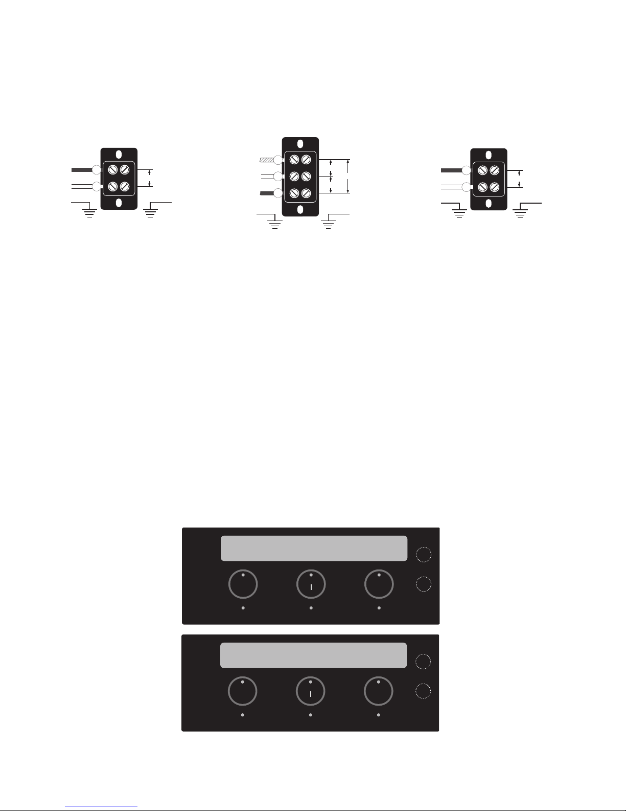
ELECTRICAL REQUIREMENTS
WARNING - The dispenser must be disconnected from the power source until specifi ed in Electrical Hook-Up.
The 120 volt version of this dispenser has an attached cordset. NOTE: If the power cord is damaged, it must be
replaced by the manufacturer or its service agent or a similarly qualifi ed person in order to avoid a hazard.
Refer to Data Plate on the Brewer, and local/national electrical codes to determine circuit requirements.
LOAD
BLK
L1
WHI/VIO
L2
GREEN GREEN
200 or 240V. A.C.
200 & 240V AC
single phase models
Note: This electrical service
consists of 2 current carrying
conductors (L1 and L2) and a
separate conductor for earth
ground.
LOAD LOADLINE LINE LINE
WHI/VIO
L2
WHI
N
BLK
L1
GREEN GREEN
120V. A.C.
208 or 240V. A.C.
120V. A.C.
120/208 & 120/240V AC
single phase models
Note: This electrical service
consists of 3 current carrying
conductors (Neutral, L1 and
L2) and a separate conductor
for earth ground
BLK
L1
WHI
N
GREEN GREEN
120V. A.C.
120V AC
single phase models
Note: This electrical service
consists of 2 current carrying
conductors (Neutral and L1)
and a separate conductor for
earth ground.
ELECTRICAL HOOK-UP
CAUTION – Improper electrical installation will damage electronic components.
1. An electrician must provide electrical service as specifi ed.
2. Using a voltmeter, check the voltage and color coding of each conductor at the electrical source.
3. Remove the right side access cover.
4. Feed the cord through the strain relief in the bottom right and connect it to the terminal block.
5. Connect the ground wire to the stud next to the terminal block and secure with #8-32 nut.
6. Connect the brewer to the power source and verify the voltage at the terminal block before proceeding. Replace the right side access cover.
7. A qualifi ed Service Technician should now enter the Service Program mode under SELECT MACHINE VOLTAGE screen and choose “YES” (RIGHT) only if supplied voltage is above 220V.
NOTE: If plumbing is to be hooked up later be sure the brewer is disconnected from the power source. If plumbing has been hooked up, the brewer is ready for Initial Set-Up.
SELECT MACHINE VOLTAGE
NO NEXT YES
LEFT
LEFT LOW
CLEAN
ON OFF
CLEAN TONIGHT
IS MACHINE 240 VOLTS
NO NEXT YES
LEFT
LEFT LOW
CLEAN
ON OFF
CLEAN TONIGHT
4
RIGHT
RIGHT LOW
RIGHT
RIGHT LOW
35352 121405
Page 5

PLUMBING REQUIREMENTS
This brewer must be connected to a cold water system with operating pressure between 20 and 90 psi (138
and 620 kPa) from a
Install a regulator in the line when pressure is greater than 90 psi (620 kPa) to reduce it to 50 psi (345 kPa).
The water inlet fi tting is
NOTE – Bunn-O-Matic recommends 1⁄4” copper tubing for installations of less than 25 feet and 3⁄8” for more
than 25 feet from the
the brewer to clean the countertop. Bunn-O-Matic does not recommend the use of a saddle valve to install the
brewer. The size and shape of the hole made in the supply line by this type of device may restrict water fl ow.
Building Codes in some areas require the installation of a back fl ow prevention device on branch water lines
that directly feed food and beverage equipment. The presence of a back fl ow prevention device can result in an
increase in water pressure that prevents the proper operation of the machine’s water inlet solenoid. When a back
fl ow prevention device is present, Bunn-O-Matic recommends the installation of a water hammer arrester on
the incoming water line between the back fl ow prevention device and the machine. Water hammer arresters are
available through a local plumbing supply house or directly from Bunn-O-Matic by ordering Bunn-O-Matic Part
Number 29350.0000 or 28919.0000.
1
⁄2” or larger supply line. A shut-off valve should be installed in the line before the brewer.
1
⁄4” fl are.
1
⁄2” water supply line. A tight coil of copper tubing in the water line will facilitate moving
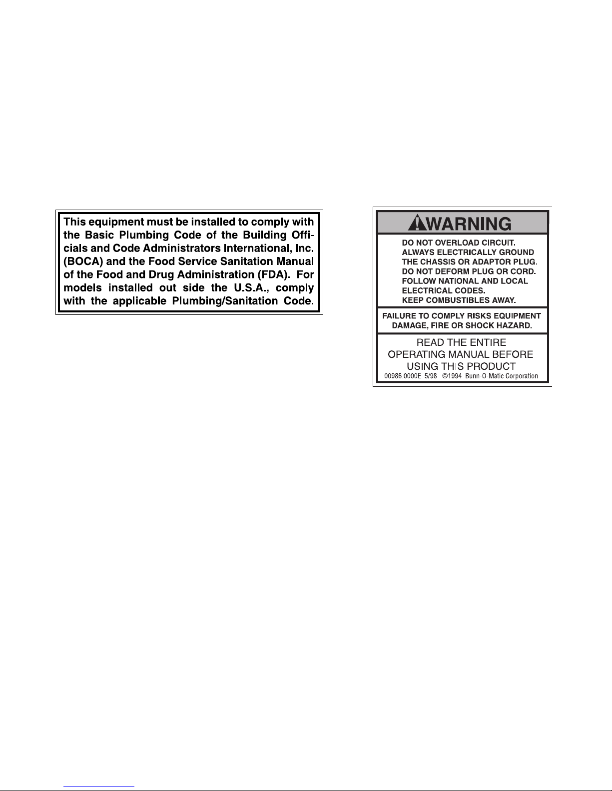
This equipment must be installed to comply with the Basic Plumbing Code of the Building
Offi cials and Code Administrators International, Inc. (BOCA) and the Food Service Sanitation Manual of the Food and Drug Administration (FDA). For models installed outside the
U.S.A., you must comply with the applicable Plumbing/Sanitation Code for your area.
PLUMBING HOOK-UP
1. Attach the fl ow control to fl are fi tting on bottom left side of brewer with copper tube assembly provided.
2. Flush the water line and securely attach it to the fl are fi tting on the water fl ow control.
3. Turn on the water supply.
4. Connect drain per instructions in the provided Drain Plumbing Kit.
5. The drip tray may also be connected to a drain. Run a 3/8” or 13/32” drill through the fi tting in the back of
the drip tray to open up the drain hole. Connect drain line to the fi tting and run the line to the drain.
5
35352 121405
Page 6

INITIAL SET-UP
1. Connect the brewer to the power source. The brewer will automatically begin to fi ll the tanks. After both tanks
are fi lled, the tank heaters will automatically turn on, one at a time. The dilution tank will heat fi rst, then the
brew tank. The tanks are fully heated when the BREWER READY indicator light is illuminated.
2. About 5 seconds after the brewer is connected to the power source, the LEFT/RIGHT LOW indicator lights
will illuminate. If a funnel is in place, the DISPOSE GROUNDS indicator will also be illuminated. Removing
the funnel for at least two seconds will reset this indicator.
OPERATING CONTROLS
1. BREWER READY INDICATOR
Indicates the water in the brew tank has reached the acceptable target temperature for brewing coffee. The
machine will not allow brewing until the indicator is illuminated. This is known as “brew Lockout” and cannot
be disabled. (Heating times are longer for 120V machines)
2. SERVICE INDICATOR
Indicates the machine has malfunctioned and requires service or clean. View the display screen for the actual
fault code. To reset any fault, remove the funnel and press both LEFT and RIGHT start switches. If the fault
returns, refer to the service decal (typically located on inside panel of door).
3. DISPOSE GROUNDS INDICATOR
Indicates that a brew or clean cycle is completed. Pull the funnel out and dump the used fi lter/grounds (or
Cleaning Packet). The indicator resets when the funnel is removed.
4. AUTOBREW ON INDICATOR
Indicates that the brewer is in the autobrew mode and will automatically start another brew cycle when a
reservoir reaches a low level. When brew cycle is completed, DISPOSE GROUNDS indicator will illuminate.
6
35352 121405
Page 7
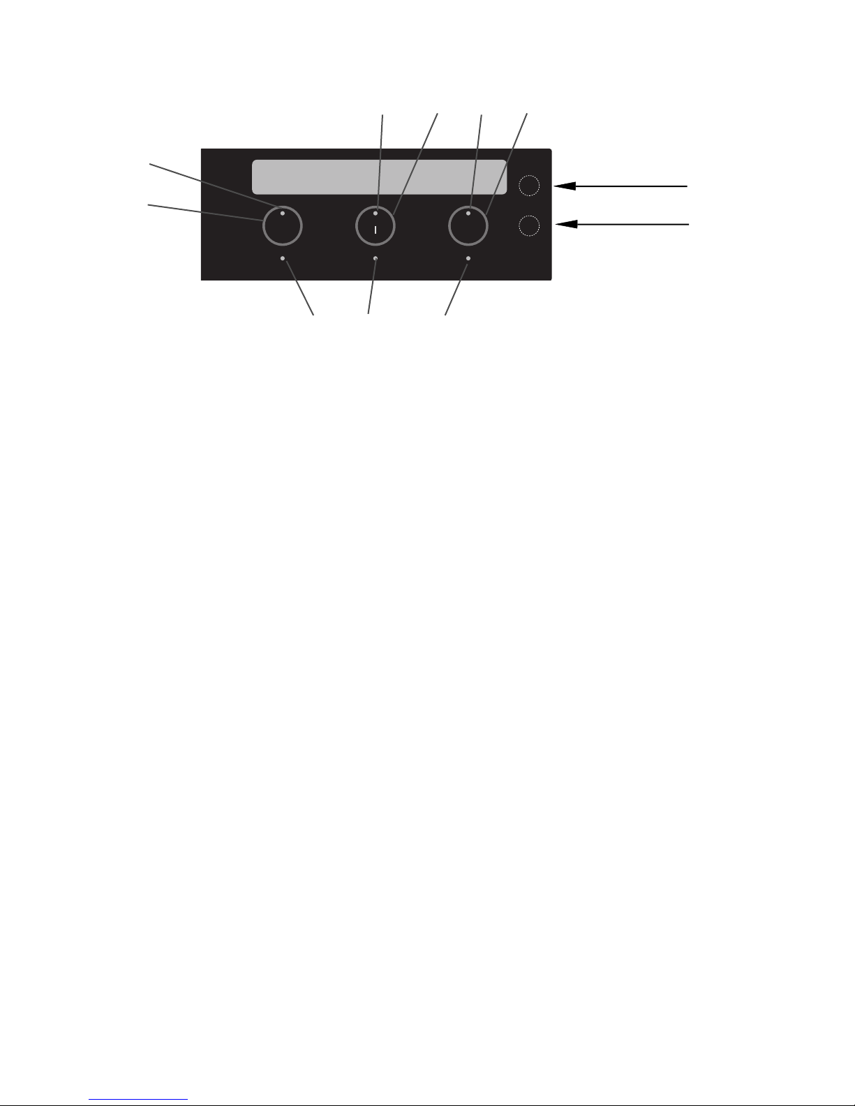
OPERATING CONTROLS (Continued)
4
8 7 6 5
3
LEFT
LEFT LOW
CLEAN
ON OFF
CLEAN TONIGHT
RIGHT
RIGHT LOW
“HIDDEN” Buttons
2 1 2
NOTE: In order for the REGULAR, DECAF, and CLEAN switch to actuate on the Manual Control machines, the
lower “Hidden” switch to the right of the “RIGHT” switch must be pressed and held.
1. CLEAN TONIGHT INDICATOR
Indicates that the brewer has missed a mandatory clean or rinse cycle.
2. LEFT/RIGHT LOW INDICATORS
Indicates the left or right reservoir has run low or out of coffee.
3. LEFT SWITCH
Momentarilly pressing and releasing this switch will start a brew cycle into the rear reservoir. Pressing the
switch after a brew cycle has started will terminate the brew.
4. LEFT BREW INDICATOR
Part of the LEFT switch, indicates that the brewer is brewing into the rear reservoir.
5. RIGHT SWITCH
Momentarilly pressing and releasing this switch will start a brew cycle into the front reservoir. Pressing the
switch after a brew cycle has started will terminate the brew.
6. RIGHT BREW INDICATOR
Part of the RIGHT switch, indicates that the brewer is brewing into the front reservoir.
7. CLEAN ON/OFF SWITCH
Momentarilly pressing and releasing this switch will set the brewer in a clean cycle mode. Pressing the switch
twice after a clean cycle has started will terminate the clean cycle.
8. CLEAN INDICATOR
Part of the CLEAN ON/OFF switch, indicates that the brewer is in a clean or rinse cycle.
7
35352 121405
Page 8

COFFEE BREWING
1. Insert a fi lter into the funnel. BUNN® part number 20138.0000 (Gourmet) or equivalent.
2. Pour the proper amount of fresh ground coffee into the fi lter and level the bed of grounds by gently shaking.
3. Slide the funnel into the funnel rails, the arrow on the funnel handle towards the front of the brewer pointing
towards the left, for brewing into the rear reservoir, or with the arrow pointing to the right, for brewing into
the front reservoir.
4. Press the appropriate button, either LEFT or RIGHT to start the brew cycle.
5. When the brew cycle is complete, the DISPOSE GROUNDS indicator light will be illuminated. Dispose of used
grounds to reset the indicator. The (red) LEFT or RIGHT LOW indicator for the reservoir brewed into should
be extinguished.
NOTE: In order for the LEFT, RIGHT, and CLEAN switch to actuate on the Manual Control machines, the lower
“Hidden” switch to the right of the “RIGHT” switch must be pressed and held.
AUTOBREW
The brewer can be staged to automatically start a brew cycle when a reservoir reaches a low level.
1. Repeat steps one through three above. When the appropriate button is pushed to start the brew cycle, the
green AUTOBREW ON indicator will light.
2. When the reservoir for which the brew cycle has been selected reaches the low level, the brew cycle will
automatically start, and the AUTOBREW ON indicator will reset.
3. To cancel the AUTOBREW mode before the brew cycle begins, remove the funnel from the brewer.
LEFT READY TO BREW
PRESS LEFT TO BEGIN
LEFT
LEFT LOW
CLEAN
ON OFF
CLEAN TONIGHT
RIGHT
RIGHT LOW
“HIDDEN” Buttons
DUMPING THE RESERVOIRS
Either or both reservoirs can be dumped of coffee by pressing and holding the corresponding or both BREW
switch(es) for fi ve seconds without a funnel in place.
NOTE: In order for the LEFT and RIGHT switches to actuate on the Manual Control machines, the lower “Hidden” switch to the right of the “RIGHT” switch must be pressed and held.
LEFT 50 (% FULL) 5 RIGHT
LOW
LEFT
CLEAN
ON OFF
RIGHT
“HIDDEN” Buttons
LEFT LOW
CLEAN TONIGHT
8
RIGHT LOW
35352 121405
Page 9
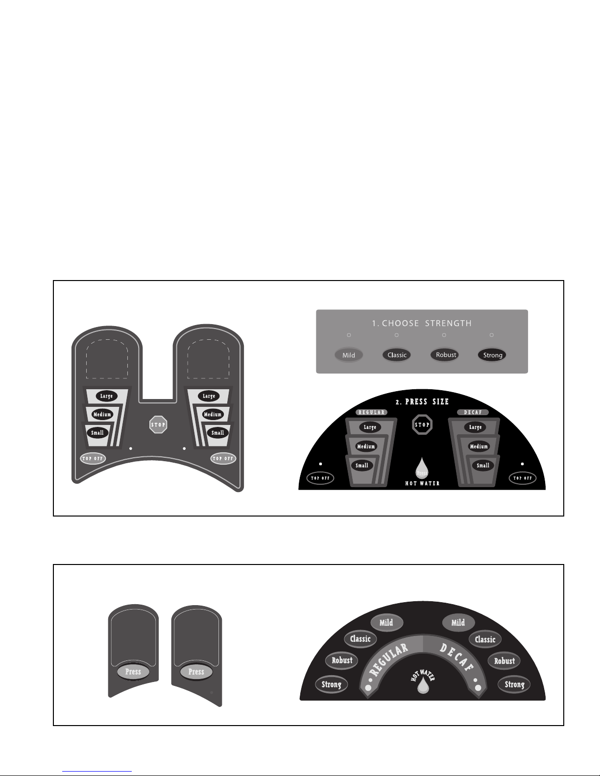
DISPENSER USE
PORTION CONTROL
1. Place cup on drip tray beneath desired dispensing tip.
2. Press button to select coffee strength desired.
3. Press appropriate cup size button. Cup will automatically fi ll and stop.
4. Automatic cup fi lling cycle may be stopped at any time by pressing the STOP button.
5. If cup did not fi ll to the desired level, press and hold the TOP-OFF button until the cup is full.
SELF SERVE
1. Place cup on drip tray beneath desired dispensing tip.
2. Press and hold button for type and strength desired until cup is full.
HOT WATER
1. Place cup on drip tray beneath hot water dispensing tip.
2. Press and hold HOT WATER button until desired amount of hot water is attained.
PORTION CONTROL
CAPPUCCINO
COFFEE
SELF SERVE
CAPPUCCINO
COFFEE
9
35352 121405
Page 10

CLEANING
CLEAN CYCLE
The clean cycle should be run daily to keep the brewer clean and in optimum operating condition. The clean
cycle is about an hour and twenty minutes total cleaning time. It is best to run the clean cycle at closing or during
off peak hours.
If at any time the CLEAN TONIGHT indicator is ON or Service light is ON, a message will appear on the display
screen.
1. Place pouch pack of cleaner fl at in the Cleaning Funnel.
2. Insert the Cleaning Funnel into the brewer. Press the “CLEAN ON/OFF” button once, to begin the cleaning
cycle.
NOTE: On Self Serve units, fi rst press and hold the lower hidden button before pressing the CLEAN button.
3. The remainder of the cleaning cycle is fully automatic. The green “CLEAN” light will remain lit during the
remainder of the cycle (which lasts about 60 minutes).
4. After the clean cycle is complete, the “Dispose Grounds” indicator will be lit. Remove the funnel and discard
the cleaner pouch pack. The unit is now ready for brewing.
NOTE: It is normal for the pumps to purge coffee from the lines during this cycle.
SOAP CLEAN RECOMMENDED - INSERT
THE FUNNEL AND PRESS THE CLEAN SWITCH
SOAP CLEAN FUNNEL
PRESS CLEAN TO BEGIN CLEAN
LEFT
CLEAN
ON OFF
RIGHT
“HIDDEN”
Button
LEFT LOW
10
CLEAN TONIGHT
RIGHT LOW
35352 042803
Page 11

PREPROGRAMMED RINSE CYCLE
The rinse cycle may be preprogrammed for automatic overnight run in case the clean cycle is ignored. Use of
a clean empty Brew funnel is required. In the event that preprogrammed rinse cycle was not complete, “RINSE
REQUIRED” will appear on the display. Brewing is disabled until the rinse cycle is complete.
MANUAL RINSE CYCLE
1. Insert a clean, empty Brew funnel into the brewer.
2. On portion control units, press and hold the “CLEAN” button for 5 seconds.
NOTE: On Self Serve units, press and hold the lower Hidden button before pressing the CLEAN button.
After the 30 minute rinse cycle is completed, the unit will be ready for brewing.
NOTE: It is normal for the pumps to purge coffee from the lines during this cycle.
RINSE REQUIRED - PLEASE INSERT
THE FUNNEL AND PRESS THE CLEAN SWITCH
LEFT
LEFT LOW
CLEAN
ON OFF
CLEAN TONIGHT
RIGHT
RIGHT LOW
RINSE REQUIRED - PRESS CLEAN
FOR 3 SECONDS TO BEGIN RINSE
LEFT
LEFT LOW
CLEAN
ON OFF
CLEAN TONIGHT
RIGHT
RIGHT LOW
“HIDDEN”
Button
EXTERIOR CLEANING
1. The use of a damp cloth rinsed in any mild, non-abrasive, liquid detergent is recommended for cleaning all
surfaces on Bunn-O-Matic equipment.
2. Check and clean sprayhead. The sprayhead holes must always remain open.
NOTE: In hard water areas, this may need to be done daily. It will prevent problems in the brewer and takes
less than a minute.
11
35352 042803
Page 12

RUNNING A RINSE SEQUENCE - CAPPUCCINO
RINSE REMINDER MESSAGE
CAPPUCCINO RINSE RECOMMENDED
Procedure
1. Open the cappuccino door.
2. Place the rinse switch in the upper “RINSE” position.
3. Close the cappuccino door.
4. Place a container capable of capturing 10 ounces or
more of hot water under the dispense tips.
5. Press and release each cappuccino dispense switch
(on Portion Control models any cup size will work)
and the corresponding fl avor will rinse for 10 seconds automatically.
6. After rinsing is complete, return the rinse switch to
the lower “RUN” position. The unit is now ready for
normal operation.
This counter can be set from 0 to 100
hours. (0 = disabled)
LEFT
LEFT LOW
CLEAN
ON OFF
CLEAN TONIGHT
RIGHT
RIGHT LOW
LOCKOUT MESSAGE (no cappuccino dispensing)
CAPPUCCINO RINSE REQUIRED
LEFT
LEFT LOW
CLEAN
ON OFF
CLEAN TONIGHT
RIGHT
RIGHT LOW
When this reminder message appears on
the display screen, a cappuccino rinse
cycle should be performed.
This counter can be set from 0 to 200
hours. (0 = disabled)
When this reminder message appears
on the display screen, the unit will not
dispense cappuccino until a rinse cycle
is performed. With this counter disabled,
the reminder only message will be displayed and the unit will still be allowed
to dispense.
12
35352 042803
Page 13

CAPPUCCINO PARTS CLEANING
Removal
1. Open the cappuccino door.
2. Remove hoppers.
14
13
19
3. Lift off steam collector (1).
4. Lift off mixing chamber (2).
18
17
16
15
5. Remove dispense tip (4) from whipper chamber (3).
6. Remove whipper chamber (3) with 1/4 turn in the clockwise direction.
7. Pull frother (6) off motor shaft.
8. Use the whipper chamber (3) as a tool to twist receptacle
(8) 1/4 turn in the clockwise direction and remove from
the studs.
9. Pull plastic slinger (9) off motor shaft.
12
10. Remove rubber seal (7) and o-ring (5) from receptacle
(8).
11
11. Lift the front edge of hopper assy (12) over the tab on
hopper support plate and slide hopper assembly out the
10
front of the dispenser.
12. Remove hopper lid (19) and empty product.
13. Pull off the ejector elbow (10).
14. Remove auger disc assy (17) by spreading the hopper
side walls, lifting agitator disc assy from hopper (12).
15. Remove auger (11) by pulling it out the front of the hopper
1
(12).
16. Remove auger drive shaft (15) by turning the auger drive
2
bracket clockwise.
17. Slide auger drive shaft (15) from auger drive shaft bushing
(16) and remove from hopper (12).
18. Remove locknut (13) from auger drive shaft bushing
9
8
7
6
5
3
(16) and remove auger drive shaft bushing from hopper
(12).
19. Wash all loose parts with a mild detergent, sanitze, rinse
4
and dry thoroughly.
Identifi cation
1. Steam collector
2. Mixing chamber
3. Whipping chamber
4. Dispense tip
5. O-ring
6. Frother
7. Rubber seal
8. Receptacle
9. Slinger
10. Ejector elbow
11. Auger spring
12. Hopper
13. Locknut
14. Drive bracket
15. Drive shaft
16. Bushing
17. Agitator disk
18. Mixing blade
19. Hopper lid
NOTE: These parts are dishwasher safe in most dishwashers however, sanitizing and cleaning is recommended in a
three compartment sink with a mild detergent using a bristle
brush.
20. Reassemble parts in reverse order.
NOTE: Make sure rubber seal (7) is installed properly in receptacle (8) and when installing receptacle to unit, verify the
seat has no gaps with the shaft.
Ensure spring is fully seated into drive shaft
before fi lling hopper.
13
35352 042803
Page 14

CLEANING/MAINTENANCE SCHEDULE
Daily Weekly Semi Annually Annually
Clean Cycle/Brush Tanks √
Rinse Sequence (Cappuccino) √
Wipe Exterior of Dispense Nozzles √
Empty/Rinse Drip Tray √
Wipe Splash Guard √
Clean Sprayhead √
Cappuccino Parts Clean √
(see below) (see below)
PREVENTIVE MAINTENANCE
Bunn-O-Matic Corporation recommends that preventive maintenance service be performed at 6 month intervals. Maintenance should be performed by a qualifi ed service technician according to the OMNI Preventive
Maintenance checklist instructions (part number 34123.0001).
14
35352 121405
Page 15

NOTES
15
35352 042803
Page 16

PROGRAMMING
Using the display on the front of the dispenser, the operator has the ability to review valuable log information and to set the Date and Time. Also, a qualifi ed Service Technician has the ability to alter or modify various
parameters such as service testing, set-up and calibration, cleaning and brew times .... all of which is password
protected.
1. Home screens: One Home Screen option displays the status of the coffee holding reservoirs in %FULL. The
indicator lights draw the operators’ attention to the display. The other Home Screen option will toggle between
four screens which display Home Screen, Date, Time and Tank Temperatures. To change the Home Screen
options, press and hold the CLEAN button for 5 seconds with no funnel in place.
Spanish displays: Press and hold the upper “Hidden” button for 5 seconds. Display will then toggle between
English/Spanish for all messages displayed. (Repeat to revert back to English)
Home screen
Option 1
LEFT 5 (%FULL) 0 RIGHT
LOW EMPTY
LEFT
LEFT LOW
CLEAN
ON OFF
CLEAN TONIGHT
RIGHT
RIGHT LOW
“HIDDEN” Buttons
16
35352 121405
Page 17

PROGRAMMING (Continued)
2. Unit data screens: To view the software version, serial number, and (if programmed) the asset number,
remove funnel, press and hold the lower “Hidden” button for 5 seconds. This screen will be displayed for 10
seconds, then will automatically change to the “View Log” screen.
SOFTWARE VERSION ##.##
SERIAL # OMNI001234 ASSET # 123456
LEFT
LEFT LOW
CLEAN
ON OFF
CLEAN TONIGHT
RIGHT
RIGHT LOW
DO YOU WISH TO VIEW LOG INFORMATION?
NO NEXT YES
LEFT
LEFT LOW
CLEAN
ON OFF
CLEAN TONIGHT
RIGHT
RIGHT LOW
Selecting NO (Left) will exit to Home Screen.
Selecting NEXT (Clean) will exit to Home Screen.
Selecting YES (Right) will allow the operator to scroll through the log information.
REAR BREW = OLDER LOG INFO ANY KEY TO
FRONT BREW = NEWER LOG INFO CONTINUE
Select LEFT to begin with the oldest info toward the most recent.
Select RIGHT to begin with the newest info back toward the oldest.
Press the CLEAN button to scroll through the log information.
Pressing both “Hidden” buttons will return to the Home Screen.
LEFT
LEFT LOW
CLEAN
ON OFF
CLEAN TONIGHT
RIGHT
RIGHT LOW
EVENT = POWER UP
B = 200° C = 190° 1/1/03 8:00AM
LEFT
LEFT LOW
CLEAN
ON OFF
CLEAN TONIGHT
RIGHT
RIGHT LOW
17
35352 121405
Page 18

PROGRAMMING (Continued)
3. Set Date and Time screens: Access by holding both “Hidden” buttons for 5 seconds with funnel removed.
Once in any screen other than home screen, Top hidden button to always select previous screen and bottom
“Hidden” button to always select next screen.
DO YOU WISH TO SET DATE AND TIME?
NO YES
LEFT
LEFT LOW
CLEAN
ON OFF
CLEAN TONIGHT
Select YES (Right) to continue to set date per screens below.
Select NO (Left) to return to Home Screen.
Press RIGHT for (-) to decrease values, or
Press LEFT for (+) to increase values.
Press CLEAN for (Next) to advance to the next screen.
SET PRESENT YEAR 2003
(-) NEXT (+)
LEFT
LEFT LOW
CLEAN
ON OFF
CLEAN TONIGHT
RIGHT
RIGHT LOW
RIGHT
RIGHT LOW
LEFT LOW
LEFT LOW
SET PRESENT MONTH JANUARY
(-) NEXT (+)
LEFT
CLEAN
ON OFF
CLEAN TONIGHT
SET PRESENT DAY OF MONTH 1
(-) NEXT (+)
LEFT
CLEAN
ON OFF
CLEAN TONIGHT
18
RIGHT
RIGHT LOW
RIGHT
RIGHT LOW
35352 121405
Page 19

PROGRAMMING (Continued)
Set Date and Time (Continued)
Press RIGHT for (-) to decrease values, or
Press LEFT for (+) to increase values.
Press CLEAN for (Next) to advance to the next screen.
SET PRESENT HOUR 12:00 AM
(-) NEXT (+)
LEFT
LEFT LOW
CLEAN
ON OFF
CLEAN TONIGHT
RIGHT
RIGHT LOW
SET PRESENT MINUTE 01
(-) NEXT (+)
LEFT
LEFT LOW
CLEAN
ON OFF
CLEAN TONIGHT
RIGHT
RIGHT LOW
If a password was entered during set-up, it will be needed to proceed beyond this point.
It is recommended to install a password and record it for use by a qualifi ed Service Technician.
ENTER PASSWORD 0
(-) NEXT (+)
LEFT
LEFT LOW
CLEAN
ON OFF
CLEAN TONIGHT
19
RIGHT
RIGHT LOW
35352 121405
Page 20

BASIC TROUBLESHOOTING
• Inspection, testing, and repair of electrical equipment should be performed only by qualifi ed service personnel.
• All electronic components have 208/240 or 120 volt ac and low voltage dc potential on their terminals. Shorting of terminals or the application of external voltages may result in board failure.
• Intermittent operation of electronic circuit boards is unlikely. Board failure will normally be permanent. If
an intermittent condition is encountered, the cause will likely be a switch contact or a loose connection at a
terminal or crimp.
• Solenoid removal requires interrupting the water supply to the valve. Damage may result if solenoids are
energized without a supply of water.
• The use of two wrenches is recommended whenever plumbing fi ttings are tightened or loosened. This will
help to avoid twists and kinks in the tubing.
• Make certain that all plumbing connections are sealed and electrical connections tight and isolated.
• This unit is heated at all times. Keep away from combustibles.
WARNING – • Exercise extreme caution when servicing electrical equipment.
• Unplug the dispenser when servicing, except when electrical tests are specifi ed.
• Follow recommended service procedures
• Replace all protective shields or safety notices
Problem
Dispenser will not operate
Service Indicator Flashing
Service Indicator On
Probable Cause
No power or incorrect voltage
Machine has detected a fault.
Three days have expired sinse last
clean cycle.
Remedy
1. Ensure power cord is properly
connected to wall receptacle.
2. Check circuit breakers or fuses.
See LCD Display for details.
Run a complete clean cycle.
20
35352 042803
Page 21

TROUBLESHOOTING (cont.)
Problem Probable Cause Remedy
Dispenser will not brew
1. No indications
2. “Autobrew On” indicator lights
steadily
3. “Dispose Grounds” indicator
lights steadily
4. “Clean Tonight” indicator on
steady
5. “Brewer Ready” indicator not
on
6. “Clean Cycle” indicator lights
No water
Reservoir is not empty
Used grounds have been left in the
brew funnel
Time limit has expired between clean
cycles
Brewer not to temperature (brew lock
out selected)
Clean or rinse cycle is running
Check plumbing and shut-off
valves.
Dispenser will brew automatically
when the reservoir empties.
(A) Remove grounds and re-load
with fresh coffee.
(B) Make sure funnel is seated
properly in the funnel rails.
Run a complete clean cycle.
Wait for “Brewer Ready” indicator
to light.
Wait for “Clean Cycle” indicator to
extinguish.
7. “Clean Tonight” indicator fl ashing
Preprogrammed Rinse cycle not
completed
Ensure brew funnel is in place and
initiate a “Rinse Cycle”.
21
35352 042803
Page 22

TROUBLESHOOTING (cont.)
Problem Probable Cause Remedy
“Autobrew ON” indicator extinguishes without brewing
Brew funnel cannot be removed
Left/Right coffee will not dispense
1. “Left/Right Low” indicator lit
2. No indication
Brew funnel was removed prior to
the start of the brew cycle
Funnel lock engaged
Reservoir contents are low
Two or more dispense strengths have
been selected
(A) Replace the brew funnel and
press the appropriate brew start
switch.
(B) Make sure funnel is seated properly in the funnel rails.
(A) Allow the “Dispose Grounds”
indicator to light before removing
brew funnel.
(B) Allow the “Clean Cycle” indicator
to extinguish before removing brew
funnel.
Brew fresh coffee.
Select only one dispense strength
at a time.
3. “Clean Tonight” indicator fl ash-
ing
4. “Clean Cycle” indicator lights
Time limit has expired between rinse
cycles
Clean or rinse cycle is running
Run a complete rinse cycle.
Wait for “Clean Cycle” indicator to
extinguish.
22
35352 121405
Page 23

TROUBLESHOOTING (cont.)
Problem Probable Cause Remedy
Coffee is “weak” or “watery”
1. Type of paper fi lters
2. Coffee
3. Sprayhead
4. Funnel loading
5. Water temperature
®
Bunn
paper fi lters should be used
for proper extraction.
A suffi cient quantity of coffee should
be used for proper extraction.
B.O.M. sprayhead #01082.0000
should be used to properly wet the
bed of ground coffee.
The Bunn
®
paper fi lter should be
centered in the funnel and the bed
of coffee should be leveled by gentle
shaking.
Check the water temperature immediately below the sprayhead with
a thermometer during a brew cycle.
The reading should not be less than
F (90.5°C).
195°
Coffee is too strong
Rinse cycle will not run
1. “Clean Tonight” indicator lit
Brew tank will not fi ll
Cappuccino tank will not fi ll
6. Incorrect dispense strength selected
Incorrect dispense strength selected
Brew funnel is not in place
No water
No water
Select the correct dispense
strength.
Select the correct dispense
strength.
Place an empty brew funnel in the
rails, press Clean ON/OFF button.
Check plumbing and shut-off
valves.
Check plumbing and shut-off
valves.
23
35352 042803
Page 24

TROUBLESHOOTING (cont.)
Problem Probable Cause Remedy
Inconsistent beverage level in concentrate reservoirs
Short cup (portion control)
Cup overfi lls (portion control)
Consistently high or low beverage
level in concentrate reservoirs
Water overfl ows fi lter
Coffee overfl ows concentrate reservoir
Improper water pressure
Incorrect cup size selected
Incorrect cup size selected
Incorrect brew time
1. Type of paper fi lters
2. No sprayhead
Incorrect brew time
Check the operating water pressure
to the dispenser. It must be between
20 and 90 psi (138 and 620 kPa).
Select the correct cup size.
Select the correct cup size.
Refer to Set-up.
BUNN-O-MATIC
®
paper fi lters should
be used for proper extraction.
Check Sprayhead.
Refer to Set-up.
24
35352 042803
Page 25

TROUBLESHOOTING (cont.)
Problem Probable Cause Remedy
CAPPUCCINO
Cappuccino will not dispense
Weak cappuccino product
1. No water
2. No power or incorrect voltage to
the dispenser
1. Incorrect water temperature
2. Auger spring installed improperly
3. Rinse/Run switch in Rinse position
Water lines and valves to the dispenser must be open.
(A1) Ensure power cord is properly
connected to wall receptacle.
(A2) Check circuit breakers or
fuses.
Place an empty container beneath
the dispense tip. Initiate a dispense
cycle and check the water temperature below the dispense tip with a
thermometer.
Ensure spring is fully seated into
drive shaft before fi lling hopper.
Open cappuccino door and check
that the switch is in the Run position.
25
35352 042803
Page 26

ELECTRICAL WIRING DIAGRAM
L1- BREWER READY
L2- SERVICE
L3- DISPOSE GROUNDS
L4- AUTOBREW ON
DOT MATRIX DISPLAY
CAPPUCCINO PORTION
CONTROL TOUCHPAD
A1- LEFT TOP-OFF
A2- LEFT SMALL
A3- LEFT MEDIUM
A4- LEFT LARGE
A5- STOP
A6- RIGHT LARGE
A7- RIGHT MEDIUM
A8- RIGHT SMALL
A9- RIGHT TOP-OFF
L1- LEFT LED
L2- RIGHT LED
3
L4
4
L3
5
L2
6
L1
7
RIGHT CAPPUCCINO
SELF SERVE
LEFT CAPPUCCINO
SELF SERVE
A3
A4
A5
A2
A1
A7
A6
L2
A9
A8
L1
J18
1
5
10
J19
1
5
7
J23
BRN
1
RED
ORN
YEL
GRN
5
BLU
VIO
C
GRY
WHI
O
BLK
10
BRN
RED
ORN
GRN
N
YEL
T
BLU
R
16
Static Shield
1
RS232
PORT
1
4
8
12
16
O
L
1
ORN
GRN
WHI/RED
RED
4
1
ORN
WHI/ORN
3
WHI/ORN
WHI/RED
RED
ORN
GRN
C
I
R
C
U
I
T
7
8
4
9
10
6
5
3
Static Shield
1
5
11
Door Switch
RED/WHI
WHI/BLK
ORN/BLK
RED/BLK
GRN/BLK
1
BLU/WHI
BLU/BLK
J26
B
BLK
1
O
RED
GRN
5
ORN
A
R
D
10
13
A1- REGULAR BREW
A2- CLEAN
A3- DECAF. BREW
B1- BOTTOM HIDDEN
B2- TOP HIDDEN
L1- REGULAR LED
L2- REGULAR LOW LED
L3- CLEAN LED
L4- CLEAN TONIGHT LED
L5- DECAF. LED
L6- DECAF LOW LED
MANUAL COFFEE TOUCHPAD
HW- HOT WATER
D1- RIGHT STRONG
D2- RIGHT ROBUST
D3- RIGHT CLASSIC
D4- RIGHT MILD
R1- LEFT STRONG
R2- LEFT ROBUST
R3- LEFT CLASSIC
R4- LEFT MILD
PORTION CONTROL
SELECT STRENGTH TOUCHPAD
A1, L1- MILD
A2, L2- CLASSIC
A3, L3- ROBUST
A4, L4- STRONG
SWITCH & LED POSITIONS
A1
A2 A3 B2B1
R4
D4HW
D1
R1
D3
R3
D2
R2
Static Shield
L1
L2
L3
L4
A4
A3
A1
A2
L5 L3
L6
120 VOLTS AC 2 WIRE
120/208-240 VOLTS AC 3 WIRE
208-240 VOLTS AC 2 WIRE
60Hz SINGLE PHASE
L4
Static Shield
L1
Static Shield
L2
1
5
11
1
5
11
J27
1
5
10
13
J28
1
5
11
J29
1
5
11
26
35352 042803
Page 27

C
O
N
T
R
O
L
C
I
R
C
U
I
T
B
O
A
R
D
Loud
Soft
J1
WHI/RED
1
RED/BLK
WHI/BLU
BLU/BLK
J8
ORN-22
1
WHI/ORN-22
WHI/BLK-22
BLK-22
PNK-22
BLU-22
J2
PNK-20
1
WHI/BLU
BLK
WHI/RED
WHI/BLU
5
WHI/VIO
WHI/GRN
WHI/BLK
WHI/BLK
BRN/WHI
10
BRN/BLK
WHI
TAN-20
BLU/BLK
WHI/VIO
15
VIO
ORN
YEL
RED
BLU
20
GRY
WHI/ORN
WHI/ORN
WHI/YEL
24
J3
BLK
1
BLK-208/240V WHI-120V
YEL
YEL
5
J41
BLK
1
WHI
J42
ORN 5VDC+
1
GRN 5VDCTAN
BLU
J5
WHI
1
BLK
J6
BLK
1
WHI
J9
WHI/VIO-22
1
GRN-22
RED
RED/BLK
BLU/BLK
5
GRN-22
VIO-22
BLU
10
J13
RED
1
BLK
J16
TAN-20
1
ORN-20
BLU
WHI/RED VDC+
WHI/ORN VDC+
6
WHI
WHI
BLK
GRN VDCGRN VDC-
12
J17
1
5
WHI
8
J7
1
Right Dispense
1
Brew Refill
Left Dilution Low
Right Dilution High
1
+
BEEPER
-
Left Dispense
SOL
BLK
BLK
Funnel Lock
Hot Water
BLK
BLK
1
1
WHI/RED
RED/BLK
WHI/BLU
BLU/BLK
ORN-22
ORN-22
BLK-22
BLK-22
BLU-22
PNK-22
10
TAN
BLU BLU
1
WHI
SOL
WHI
Front Reservoir Drain
SOL
SOL
SOL
SOL
SOL
Brew
SOL
Transformer
120/24V
or
240/24V
TAN-20
ORN-20
RINSE/RUN
SWITCH
Closed-RUN
Static Shield
1
TAN
BLU
1
Dilution Refill
Left Dilution High
Right Dilution Low
Rear Reservoir Drain
1
Funnel
Sensor
Brew
Clean
Open-RINSE
BLKBLK
BLK
SOL
SOL
Left Tube Heater
Right Tube Heater
1
RED
-+
M
Left
BLK
RED
-+
M
Right
BLK
BLU-14
WHI
SOL
SOL
SOL
Brew Tank
Temp. Sensor
t
Clock
Left Whipper
M
Left Dispense
SOL
Right Whipper
M
Right Dispense
SOL
RED
M
RED BLK
Dilution
Tank Heater
Dilution Tank
Temp. Sensor
t
Left Hopper
M
WHI
WHI
WHI
WHI
WHI
WHI
WHI
WHI
WHI
WHI
WHI
WHI
Right Hopper
BLK-22
WHI
BLK
BLK-14
Left
1
Pump
Speed
Sensor
Right
1
Pump
Speed
Sensor
GRN
120VAC 2 WIRE
208-240VAC 2 WIRE
N (120V, 2-WIRE)
L1
L2 (208/240V, 2-WIRE)
BLK
WHI
20 Amp
Fuse
20 Amp
Fuse
WHI/VIO
BLK
WHI
ABC
Triac
Dilution Limit
BLK-14
Brew Tank
Heater
BLU-14 BLK-14
Front
Reservoir
GRN
Keep Warm
Heater
GRN
WHI
WHI
BLU
1
4
WHI
GRN
BLU/BLK
WHI/BLU
WHI WHI WHI
Brew Tank
Level Sensing
Dilution Tank
Level Sensing
WHI
WHI WHI
GRN
BLU
BLK-14
GRN
TAN
Rear
Reservoir
GRN
Keep Warm
Heater
Fan
M
120/208-240 VAC 3 WIRE
20 Amp
Fuse
Triac
Brew Limit
GRN
WHI
WHI
1
WHI
GRN
WHI/RED
Rear
Conductance Chamber
Front
Conductance Chamber
BLK
L1
BLK
BLK
ABC
BLU
4
RED/BLK
N
WHI
WHI/VIO
WHI/VIO
L2
WHI
20 Amp
WHI/VIO
Fuse
GRN
ABC
BLK
WHI
WHI/VIO
5
11
6
11
L1- LEFT LED
L2- RIGHT LED
R1- LEFT TOP-OFF
R2- LEFT SMALL
R3- LEFT MEDIUM
R4- LEFT LARGE
HW- HOT WATER
STOP- STOP
D1- RIGHT TOP-OFF
D2- RIGHT SMALL
D3- RIGHT MEDIUM
D4- RIGHT LARGE
R2
D1R3R1HWD2
STOPD3
D4
COFFEE PORTION CONTROL TOUCHPAD
27
R4
L1
L2
35352 042803
 Loading...