

Page 1

CRESCENDO
INSTALLATION & OPERATING GUIDE
BUNN-O-MATIC CORPORATION
POST OFFICE BOX 3227
SPRINGFIELD, ILLINOIS 62708-3227
PHONE: (217) 529-6601 FAX: (217) 529-6644
To ensure you have the latest revision of the Operating Manual, or to view the Illustrated Parts
Catalog, Programming Manual, or Service Manual, please visit the Bunn-O-Matic website, at
www.bunn.com. This is absolutely FREE, and the quickest way to obtain the latest catalog and
manual updates. For Technical Service, contact Bunn-O-Matic Corporation at 1-800-286-6070.
52384.0001B 09/17 ©2016 Bunn-O-Matic Corporation
Page 2

BUNN-O-MATIC COMMERCIAL PRODUCT WARRANTY
Bunn-O-Matic Corp. (“BUNN”) warrants the BUNN Crescendo as further described below for a warranty period of 1 year parts
and labor.
These warranty periods run from the date of installation. BUNN warrants that the equipment manufactured by it will be commercially free of defects in material and workmanship existing at the time of manufacture and appearing within the applicable
warranty period. This warranty does not apply to any equipment, component or part that was not manufactured by BUNN or that,
in BUNN’s judgment, has been affected by misuse, neglect, alteration, improper installation or operation, improper maintenance
or repair, non periodic cleaning and descaling, equipment failures related to poor water quality, damage or casualty. This warranty is conditioned on the Buyer 1) giving BUNN prompt notice of any claim to be made under this warranty by telephone at
(217) 529-6601 or by writing to Post Office Box 3227, Springfield, Illinois 62708-3227; 2) if requested by BUNN,
shipping the defective equipment prepaid to an authorized BUNN service location; and 3) receiving prior authorization from
BUNN that the defective equipment is under warranty. Additionally, the following is excluded from the warranty period:
Warranty Exclusions:
• Parts such as, but not limited to, hoppers and lids, drip trays, and plastic parts damaged due to improper handling or cleaning agents.
• Replacement of wear items such as, but not limited to, O-rings, gaskets, silicone tubes, hoses, and valve seats.
• Repairs made necessary due to poor water quality such as dispense valves, water inlet valves, scaling in the steam or hot
water boilers. (Total Hardness recommended range of 4-7 gpg constant).
• Improper voltage. (See equipment operations manual for voltage specifications).
• Failure to use BUNN approved cleaning supplies constitutes improper maintenance.
• Failure to have required preventive maintenance performed by BUNN technician or authorized espresso service provider.
• Parts replaced under the terms of this warranty carry the remainder on the machine’s parts warranty term, or 60 days,
whichever is greater.
THE FOREGOING WARRANTY IS EXCLUSIVE AND IS IN LIEU OF ANY OTHER WARRANTY, WRITTEN OR ORAL, EXPRESS OR
IMPLIED, INCLUDING, BUT NOT LIMITED TO, ANY IMPLIED WARRANTY OF EITHER MERCHANTABILITY OR FITNESS FOR A
PARTICULAR PURPOSE. The agents, dealers or employees of BUNN are not authorized to make modifications to this warranty
or to make additional warranties that are binding on BUNN. Accordingly, statements by such individuals, whether oral or written, do not constitute warranties and should not be relied upon. If BUNN determines in its sole discretion that the equipment
does not conform to the warranty, BUNN, at its exclusive option while the equipment is under warranty, shall either 1) provide
at no charge replacement parts and/or labor (during the applicable parts and labor warranty periods specified above) to repair
the defective components, provided that this repair is done by a BUNN Authorized Service Representative; or 2) shall replace the
equipment or refund the purchase price for the equipment.
THE BUYER’S REMEDY AGAINST BUNN FOR THE BREACH OF ANY OBLIGATION ARISING OUT OF THE SALE OF THIS EQUIPMENT, WHETHER DERIVED FROM WARRANTY OR OTHERWISE, SHALL BE LIMITED, AT BUNN’S SOLE OPTION AS SPECIFIED HEREIN, TO REPAIR, REPLACEMENT OR REFUND. In no event shall BUNN be
liable for any other damage or loss, including, but not limited to, lost profits, lost sales, loss of use of equipment, claims of
Buyer’s customers, cost of capital, cost of down time, cost of substitute equipment, facilities or services, or any other special,
incidental or consequential damages.
392, A Partner You Can Count On, Air Infusion, AutoPOD, AXIOM, BrewLOGIC, BrewMETER, Brew Better Not Bitter, BrewWISE,
BrewWIZARD, BUNN Espress, BUNN Family Gourmet, BUNN Gourmet, BUNN Pour-O-Matic, BUNN, BUNN with the stylized red
line, BUNNlink, Bunn-OMatic, Bunn-O-Matic, BUNNserve, BUNNSERVE with the stylized wrench design, Cool Froth, DBC, Dr.
Brew stylized Dr. design, Dual, Easy Pour, EasyClear, EasyGard, FlavorGard, Gourmet Ice, Gourmet Juice, High Intensity, iMIX,
Infusion Series, Intellisteam, My Café, Phase Brew, PowerLogic, Quality Beverage Equipment Worldwide, Respect Earth, Respect
Earth with the stylized leaf and coffee cherry design, Safety-Fresh, vemycoffee.com, Scale-Pro, Silver Series, Single, Smart Funnel, Smart Hopper, SmartWAVE, Soft Heat, SplashGard, The Mark of Quality in Beverage Equipment Worldwide, ThermoFresh,
Titan, trifecta, TRIFECTA (sylized logo), Velocity Brew, Air Brew, Beverage Bar Creator, Beverage Profi t Calculator, Brew better,
not bitter., Build-A-Drink, BUNNSource, Coffee At Its Best, Cyclonic Heating System, Daypart, Digital Brewer Control, Element,
Milk Texturing Fusion, Nothing Brews Like a BUNN, Picture Prompted Cleaning, Pouring Profi ts, Signature Series, Sure Tamp,
Tea At Its Best, The Horizontal Red Line, Ultra are either trademarks or registered trademarks of Bunn-O-Matic Corporation. The
commercial trifecta® brewer housing configuration is a trademark of Bunn-O-Matic Corporation.
2
52384.1 031314
Page 3

USER NOTICES
The notices on this dispenser should be kept in good condition. Replace unreadable or damaged labels.
00656.0001
00986.0000
12368.0002
37881.0000
00824.0002
3
52384.1 062217
Page 4

CE REQUIREMENTS
• This appliance must be installed in locations where it can be overseen by trained personnel.
• For proper operation, this appliance must be installed where the temperature is between 5°C to 35°C.
• Appliance shall not be tilted more than 10° for safe operation.
• An electrician must provide electrical service as specified in conformance with all local and national codes.
• This appliance must not be cleaned by water jet.
• This appliance can be used by persons aged from 18 years and above if they have been given supervision or
instruction concerning use of the appliance in a safe way and if they understand the hazards involved.
• Keep the appliance and its cord out of reach of children aged less than 18 years.
• Appliances can be used by persons 18 years and above with reduced physical, sensory or mental capabilities
or lack of experience and knowledge if they have been given supervision or instruction concerning use of the
appliance in a safe way and understand the hazards involved.
• Children under the age of 18 years should be supervised to ensure they do not play with the appliance.
• If the power cord is ever damaged, it must be replaced by the manufacturer or authorized service personnel
with a special cord available from the manufacturer or its authorized service personnel in order to avoid a hazard.
• Machine must not be immersed for cleaning.
• Cleaning and user maintenance shall not be made by children unless they are older than 18 years and supervised.
• This appliance is intended to be used in household and similar applications such as:
– staff kitchen areas in shops, offices and other working environments;
– by clients in hotels, motels and other residential type environments;
– bed and breakfast type environments.
• This appliance not intended to be used in applications such as:
– farm houses;
• Access to the service areas permitted by Authorized Service personnel only.
• The A-Weighted sound pressure level is below 70 dBA.
NORTH AMERICAN REQUIREMENTS
• This appliance must be installed in locations where it can be overseen by trained personnel.
• For proper operation, this appliance must be installed where the temperature is between 41°F to 95°F (5°C to
35°C).
• Appliance shall not be tilted more than 10° for safe operation.
• An electrician must provide electrical service as specified in conformance with all local and national codes.
• This appliance must not be cleaned by pressure washer.
• This appliance can be used by persons aged from 18 years and above if they have been given supervision or
instruction concerning use of the appliance in a safe way and if they understand the hazards involved.
• Keep the appliance and its cord out of reach of children aged less than 18 years.
• Appliances can be used by persons 18 years and above with reduced physical, sensory or mental capabilities
or lack of experience and knowledge if they have been given supervision or instruction concerning use of the
appliance in a safe way and understand the hazards involved.
• Children under the age of 18 years should be supervised to ensure they do not play with the appliance.
• If the power cord is ever damaged, it must be replaced by the manufacturer or authorized service personnel
with a special cord available from the manufacturer or its authorized service personnel in order to avoid a hazard.
• Machine must not be immersed for cleaning.
• Cleaning and user maintenance shall not be made by children unless they are older than 18 years and supervised.
• This appliance is intended for commercial use in applications such as:
– staff kitchen areas in shops, offices and other working environments;
– by clients in hotel and motel lobbies and other similar types of environments;
• Access to the service areas permitted by Authorized Service personnel only.
4
52384.1 062217
Page 5

INITIAL SET-UP
1. Remove drip tray and cover from the parts box. Assemble the cover to the drip tray, then slide under
the front door of the machine, engaging the rear of the drip tray into the opening in the lower front of the
machine..
2. Remove the espresso brew group from the parts box.
3. Slide tube onto elbow fitting on upper left side of
espresso group head as shown in Figure 1.
Figure 1
P4375
4. Place groove on lower front of group head over mounting
bar on espresso drive as shown in Figure 2.
Groove
Mounting
Bar
Figure 2
P4376
5
52384.1 062217
Page 6

INITIAL SET-UP - continued
6. Rotate the top of group head toward rear of machine until it
snaps into place as shown in Figure 3.
7. Slide red lock to the right until it snaps into place as shown
in Figure 4.
8. Install group head tube into quick connect fitting on
bottom of espresso drive, insuring that the tube is fully
inserted as shown in Figure 5.
Brew Tube
Connection
Figure 3
Figure 4
P4377
P4378
Figure 5
6
P4379
52384.1 062217
Page 7
INITIAL SET-UP - continued
9. Remove the bean hopper from the parts box. Align the
bean hopper so that the collar on the bottom of the
bean hopper will engage the opening in the grinder as
shown in Figure 6.
10. When the hopper is in place on the grinder, pull the
hopper gate all the way forward to allow beans into the
grinder, then lock hopper in place as shown in Figure 7.
Figure 6
CAPACITY
Figure 7
1. Brew chamber has a capacity rating of 5 gm minimum up to 15 gm maximum of espresso grind coffee.
2. Brewer has a peak capacity of 60 single (small) espresso shots per hour.
ELECTRICAL REQUIREMENTS
CAUTION - The dispenser must be disconnected from the power source until specified in Electrical Hook-Up.
Electrical Hook-Up
CAUTION - Improper electrical installation will damage electronic components.
1. An electrician must provide electrical service as specified.
2. Using a voltmeter, check the voltage and color coding of each conductor at the electrical source.
3. Connect the dispenser to the power source.
4. If plumbing is to be hooked up later be sure the dispenser is disconnected from the power source. If
plumbing has been hooked up, the dispenser is ready for Initial Fill & Heat.
120 & 220-240 volt ac models
120V
Models
220-240 VOLT Models
7
Note: This electrical service consists of 2 current
carrying conductors (L1 and Neutral) and a
separate conductor for chassis ground.
52384.1 062217
Page 8

PLUMBING REQUIREMENTS
This dispenser must be connected to a cold water system with operating pressure between 138 - .620 MPa
(20 and 90 psi) from a 1⁄2” or larger supply line. A shut-off valve should be installed in the line before the dispenser.
Install a regulator in the line when pressure is greater than .620 MPa (90 psi) to reduce it to .345 MPa (50 psi). The water
inlet fitting is 3/4 British Parallel Pipe.
NOTE - Bunn-O-Matic recommends 6mm copper tubing for installations of less than 25 feet and 8mm for more than 25
feet from the water supply line. At least 18 inches of an FDA approved flexible beverage tubing, such as reinforced braided
polyethylene or silicone, before the dispenser will facilitate movement to clean the counter top. Bunn-O-Matic does not
recommend the use of a saddle valve to install the dispenser. The size and shape of the hole made in the supply line by
this type of device may restrict water flow.
As directed in the International Plumbing Code of the International Code Council and the Food Code
Manual of the Food and Drug Administration (FDA), this equipment must be installed with adequate
backflow prevention to comply with federal, state and local codes. For models installed outside the
U.S.A., you must comply with the applicable Plumbing /Sanitation Code for your area.
NOTE - If a backflow preventer is required by code, a shock arrestor should be installed between backflow preventer and
dispenser. Installing the shock arrestor as close to the dispenser as possible will provide the best results.
NOTE - Water pipe connections and fixtures directly connected to a potable water supply shall be sized, installed and
maintained in accordance with federal, state and local codes.
PLUMBING HOOK-UP
NOTE: The plumbing connection is located on the back of the unit, using the water line included with some models, that
connects to a 3/8” male flare.
1. Flush the water line and securely attach it to the valve threads on the rear of the dispenser.
2. Turn on the water supply.
INITIAL FILL & HEAT
1. Turn on the water supply, connect power to the dispenser, and place the main power switch on the rear of the machine
to the ON position.
2. Water will automatically flow into the soluble tank to the proper level, then shut off. This will take less than five
minutes.
3. The screen on the front door will display FILL ESPRSO TANK. Press the button under START.
4. The screen will display MOVING BREW CHAMBER, ESP TANK FILLING, and the espresso tank will begin filling. This
may take several minutes.
5. When water dispenses from the espresso nozzle into the drip tray, press YES under WATER DISPENSED? to stop the
tank filling.
6. The tanks will then begin heating. When the tanks have completed heating, the display will read “READY TO BREW
SELECT SIZE”.
PRESET TANK TEMPERATURE
The tank temperatures have been preset at the factory to 80°C (180°F) for the soluble tank, and 102°C (215°F) for the
espresso tank. Bunn recommends that to provide the best quality beverage, the installer adjust the tank temperature to
the powder product manufacturers recommended temperature for the hot powder product being used.
7. Fill the hopper(s) with the dry product to be dispensed.
8. Fill the bean hopper with the whole beans to be ground and brewed.
LIQUID LEVEL CONTROL
The system automatically maintains the soluble hot water tank’s level by energizing the refill solenoid when the water level
drops below the liquid level probe. If the system has not successfully refilled, a refill error occurs. When a refill error
occurs, the refill solenoid is de-energized. Once the cause of the refill error has been investigated and cured, the system
can be reset by either cycling the power to the machine (at least five seconds) using the main power switch at the rear of
the machine, or by entering one of the program modes (see Programming Modes.)
8
52384.1 062217
Page 9

Filling Soluble Hoppers
1. Remove packing material from on top of the powder hoppers.
2. Remove powder hoppers by lifting the front of the powder
hopper until the peg on the bottom of the hopper clears the hole in
the mounting plate (see Figure 1). Then pull the hopper forward to
remove.
3. Set the hoppers on the counter, and push the slide gates on the
front of the discharge chutes inward (see Figure 2) to close the
gates.
Figure 1
4. Remove hopper lids and fill the hoppers with appropriate soluble
products. Default menu is milk product left hopper, chocolate is
center hopper, and vanilla is right hopper. Replace hopper lids.
5. Reinstall hoppers back into machine, make sure peg on bottom of
hopper drops into locating hole on hopper platform.
6. After hoppers are installed, discharge chutes must be rotated as
shown in Figure 3.
9
Figure 2
Figure 3
52384.1 062217
Page 10

OPERATING CONTROLS AND INTERFACE
1. Cup Size Buttons: Momentarily pushed to select beverage size to dispense.
2. Dispense Buttons: Momentarily pushed to dispense selected beverage
3. LED indicators: Illuminates when the adjoining button has been selected.
4. Stop button: Pressing the stop button during dispensing will stop the dispense sequence.
1
4
3
OPERATING THE DISPENSER
The NORMAL/PROGRAM/RINSE switch must be in the NORMAL position
1. Place a cup on the drip tray beneath the dispense nozzle.
2. In the area marked “1” of the control panel:
a. Select desired beverage size, small or large cup. This selection is mandatory for dispensing.
3. In the area marked “2” of the control panel:
a. Press the button to dispense the desired beverage. Dispensing is portion controlled, and will automatically stop
when the correct amount of beverage has been dispensed.
10
22
52384.1 062217
Page 11

MODIFYING THE TOUCH SWITCH FUNCTIONS
The function of the touch switch can be modified in four different ways:
1. Set for single cup size dispensing.
2. Move any default beverage from one switch location to another.
3. Disable a dispense switch.
4. Create a “custom” beverage in any switch location.
SINGLE CUP SIZE DISPENSING
In this mode, a selection can be made to dispense one cup size beverage only. When the SINGLE cup size
beverage mode is selected, the large and small cup size buttons are disabled. To dispense a beverage, press
only the dispense button of the beverage desired. It is recommended that the touch switch graphic insert be
replaced with a new graphic that does not show the large and small cup button in this mode. Reference PROGRAMMING SWITCHES diagram on page 30, and on the flow chart on page 33.
1. In the PROGRAM mode, use the LARGE cup size button, top far right, to navigatge to the “RECIPE SET
UP?” screen.
2. Press the button under “YES” (button “B”), and “USER SELECT MODE” screen will appear.
3. To change from a “MULTI”, small and large cup sizes, to a “SINGLE” cup size, press the button under
“SINGLE”, (button “D”), and “SINGLE” will flash to verify the selection.
4. Press to accept the selection and exit to the “PROGRAM MODE” screen.
5. When complete, return to the NORMAL\PROGRAM\RINSE switch to the NORMAL position.
CHANGING DEFAULT BEVERAGE SWITCH LOCATION or DISABLING A DISPENSE SWITCH
Any default beverage can be moved to a different switch location, or any dispense switch can be disabled. It is
recommended that the touch switch graphic insert be replaced with one that matches the beverage reassignments made in this mode. Reference PROGRAMMING SWITCHES diagram on page 30, and on the flow chart
on page 34.
1. In the PROGRAM mode, use the LARGE cup size button, top far right, to navigate to the “RECIPE SETUP?”
screen.
2. Press the button under “YES” (button “B”) and then the LARGE cup size button untill the screen displays
the “SETUP SW ## RECIPE” for the desired switch to be modified.
3. In the “SETUP SW ## RECIPE” screen, press the button under “YES” (button “B”) to modify that switch
setup.
4. Press the button under (+), (button “B”) to scoll through the recipe names until the desired beverage is
displayed. If “DISABLE” is selected as a recipe, this dispense switch will be disabled.
5. After the desired recipe name is displayed, press the LARGE cup size button to advance to the “SW #
SMALL TM” screen. The amount of soluble product in the beverage can be adjusted by using the (-) (button “D”) or the (+) (button “B”) button to change the dispense time.
6. Press the LARGE cup size button to advance to the “SW # LARGE TM” screen. The amount of soluble
product in the beverage can be adjusted byusing the (-) (“D”) or the (+) (“B”) button to change the dis-
pense time. Press to exit this menu.
7. Return the NORMAL\PROGRAM\RINSE switch to the NORMAL position.
11
52384.1 062217
Page 12

MODIFYING THE TOUCH SWITCH FUNCTIONS - CONTINUED
CREATING A “CUSTOM” BEVERAGE
In this mode, a “CUSTOM” beverage may be created in any dispense switch location. A CUSTOM beverage consists
of product from one or two soluble hoppers, and may include a shot of espresso. Or, instead of a soluble component,
“DILUTION” may be selected to pair with an espresso shot to create an AMERICANO type beverage. It is recommended
that the touch switch graphic insert be replaced with one which matches the beverage reassignments made in this mode.
Reference PROGRAMMING SWITCHES diagram on page 30, and on the flow chart on page 35.
1. In the PROGRAM mode, use the LARGE cup size button, top far right, to navigate to the “RECIPE SETUP?”
screen.
2. Press the button under “YES” (button “B”) and “USER SELECT MODE” screen will appear.
3. Press the LARGE cup size button until the screen displays the “SETUP SW ## RECIPE” for the desired switch to be
modified.
4. Press the button under (+), (button “B”) to scoll through the recipe names until “CUSTOM” is displayed.
5. Press the LARGE cup button to advance to the “SW # SMALL TM” screen. The amount of soluble dilution water in
the beverage can be adjusted by using the (-) (“D”) or the (+) (“B”) button to change the dispense time. Note: This
is the total soluble dilution water dispense time for either a single soluble component or both soluble components.
It is also the dispense time if DILUTION is selected. The nominal flow rate is 22ml per second, (.74 oz/sec). So the
dispense time can be estimated by dividing the volume of the soluble componet or dilution water desired by the flow
rate per second. This does not account for the actual soluble powder product.
6. Press the LARGE cup size button to advance to the “SW # LARGE TM” screen. The volume of soluble or dilution
water can be adjusted as in step 5.
7. Press the LARGE cup size button to advance to the “ESPRESSO SHOT?” screen. The default selection of “YES” will
be flashing. If an espresso shot is to be included in the recipe, press the LARGE cup button for yes. If an espresso
shot is not to be included, press the butoon under “NO” (button “D”), then press the LARGE cup button to advance.
The default espresso shots settings will be included in the recipe, a small shot for the small beverage, and large shot
for the large beverage.
8. In the 1st POWDER/DIL” screen, use the (+) )”B”) button to scroll to the hopper, LEFT, CENTER, or RIGHT, that the
soluble product is to be dispensed from. Select the soluble hopper for the first ingredient, or DILUTION for hot water
only.
9. Press the LARGE cup button to move to the “2nd POWDER/DIL” screen. Use the (+) (“B”) button to select the next
ingredient hopper, or “NONE” if only one soluble ingredient is to be used.
10.Press the LARGE cup button. If more than one soluble hopper has been selected, the “HOPPER #### PORTION”
screen will appear. In this screen, use the (+) (“B”) and (-) (”D”) button to set the percentage portion of the total
soluble ingredients you wish this hopper to consist of. Selection value may be between 15 and 85%.
11.Press the LARGE cup button to advance to the “HOPPER #### STR” screen. Use the (+) (“B”) and (-) (“D”) button to
adjuste the amount (strength) of the soluble ingredient to be dispensed.
12.Press the LARGE cup button. If a second soluble ingredient was selected, the “HOPPER #### STR” screen will be
displayed. Use the (+) (“B”) and (-) (“D”) button to adjust the amount (strength) of the soluble ingredient to be
dispensed.
13.Press the LARGE cup button to go back to the switch selection screen, or to exit the RECIPE SETUP? screens.
12
52384.1 062217
Page 13

CHANGE THE DISPLAY LANGUAGE
The display language can be changed in the PROGRAMMING MENU.
To access the “SELECT LANGUAGE” menu:
1. Open the door and place the NORMAL/PROGRAM/RINSE switch in the
PROGRAM position. (Figure 1)
1. Press buttons 1-5-9-10 in sequence. (Figure 2)
2. Use the (-) or (+) buttons to scroll through the available languages.
(Figure 3)
3. Press the button to accept the new selection and exit to the
programming menu.
Figure 1
ENERGY SAVER MODE
In this mode, the machine will operate in a low power mode during off
hours to save energy. The display backlight will be turned off, and the
display message will toggle between “Energy Saver/Mode Enabled” and
“Change to Normal/Mode to Clear”. The dispense buttons are disabled
so that no beverage dispensing is allowed. The tank refill and powder
(soluble) tank heater are disabled. The espresso tank temperature setting
is reduced to 130ºF (54ºC).
To enable the Energy Saver mode:
1. In PROGRAM mode, press the LARGE cup button (button “A”), to
navigate to the “LOCKS/DISABLES” menu.
2. Press the button under “YES” (button “B”) and then the LARGE cup
size, (button “A”), until the screen displays “ENERGY SAVER?”.
3. In the default menu, “NO” will be flashing. Press the button under
“YES” to enable the Energy Saver mode.
4. When “YES” is flashing on the display, press the button under “EXIT” to
return to the main screen.
5. Place the NORMAL/PROGRAM/RINSE switch to the NORMAL position.
1
5
9
Figure 2
SELECT LANGUAGE
(-) ENGLISH (+)
Scroll through available languages
using these buttons.
Figure 3
10
To place the unit in the ENERGY SAVER mode, open the door, and place
the NORMAL/PROGRAM/RINSE switch in the RINSE position. After ten
minutes with the switch in the RINSE position, the ENERGY SAVER mode
will become active. If a rinse cycle has taken place, and the switch is left
in the RINSE position, the ENERGY SAVER mode will become active ten
minutes after the rinse cycle was completed. To exit the ENERGY SAVER
mode, return the NORMAL/PROGRAM/RINSE switch to the NORMAL
position.
13
52384.1 091217
Page 14

THROUGH COUNTER OPTION
The machine can be setup to dispose of the used coffee
grounds through an opening in the counter, into a. waste
bin, for higher waste capacity.
Countertop and Machine Modifications for
Through Counter Waste Option:
1. Use template (Bunn #54427.0000) to locate the
cutout hole in the countertop.
2. Open the front door on Crescendo, and remove the
grounds bin.
3. Remove the two screws that secure the grounds bin
support panel, then remove the panel.
4. Remove screw holding the chassis bottom cover,
then remove the cover.
5. Used coffee puck will now fall through the opening in
the chassis.
6. Position the Crescendo so that the opening in the
bottom of the machine coincides with the hole in the
countertop.
7. To direct the brewing waste water through the
counter, disconnect the drain tube from the fitting on
the bottom of the espresso drive.
8. Connect a 5MM ID tube to the drain fitting, and direct
the tube through the opening in the bottom of the
chassis.
Software Setup for Through Counter Option:
Remove the grounds bin
Remove grounds bin support panel
1. Power the machine.
2. In the PROGRAM mode, use the LARGE cup, (button
“A”), to navigate to the “LOCKS/DISABLES” menu.
3. Press the button under “YES” (button “B”) and then
the LARGE cup size, (button “A”), until the screen
displays the “PUCK BIN” screen.
4. In the default menu, “YES” will be flashing. Press the
button under “NO” to disable the PUCK BIN mode.
5. When “NO” is flashing on the display, press the
button under “EXIT” to return to the main screen.
6. Place the NORMAL/PROGRAM/RINSE switch to the
NORMAL position.
14
Remove the chassis bottom cover
Connect a 5MM ID tube to the drain fitting
52384.1 091217
Page 15

GENERAL CLEANING
The use of a damp cloth rinsed in any mild, non-abrasive, liquid detergent
is recommended for cleaning all surfaces on Bunn-O-Matic equipment.
Exterior Surfaces:
• Do not use any abrasive materials.
• Use a soft, dry cloth to wipe down the exterior surfaces of
the dispenser to maintain the luster of the
stainless steel finish.
• Wash the stainless steel exterior surfaces of the dispenser
with warm, soapy water. Rinse with warm,
clear water. If the water is hard, wipe the dispenser dry with a
soft cloth to prevent water spotting.
• Stainless steel polish may be used if it is sprayed on a cloth
before the cloth is used to wipe down the
exterior surfaces of the dispenser.
DAILY: PARTS WASHING
1. Remove and wash the drip tray and drip tray cover in a
mild detergent solution. Rinse thoroughly.
2. Wipe the lower front panel, door, and cabinet with a clean
damp cloth.
WEEKLY: PARTS WASHING
1. Remove the elbows and slide gates from all hoppers.
Disconnect the elbows from the outlets of both mixing
chambers.
2. Remove the powder mixing chambers, steam traps,
frothers and mixing chamber bases.
3. Remove the dispense hoses from the dispense nozzle
assembly.
4. Clean all parts removed in warm soapy wataer. Use Bunn
P/N 26367.0000 or 49827.0000 cleaning brush provided to
clean bores and orifices. Rinse in cold water.
5. Prepare one-gallon (3.8 liter) of sanitizing solution with
at least 100 ppm of available chlorine in 120°F (48.9°C)
water. Soak all cleaned parts in sanitizing solution for 5
minutes, then allow to air dry.
6. Rinse cleaning brush, dip in sanitizing solution, and brush
the bore of both dispense nozzles
NOTE: Repeat this procedure for each nozzle separately.
7. When reassembling parts, be sure to align arrow on frother
disk with flat on whipper motor shaft, and rotate tab on
whipper base clock wise to the vertical position to lock
mixing chamber.
15
52384.1 062217
Page 16

1 x 24h
1. Rinse out Whipper Chambers by placing the
RUN/PROGRAM/RINSE switch in the RINSE position,
then press the button under RINSE followed by pressing
any beverage dispense button.
2. Push the slide gates on the front of the hopper elbows
inward to close. Remove hoppers, refill with product, and
replace hoppers into dispenser.
3. Empty Drip Tray and wash in a solution of dish detergent.
7
1 x 7d
1. Lave la cámara de batido colocando RUN/PROGRAM/RINSE en la
posición de lavado RINSE, y apretar el botón bajo RINSE. Luego
aprete cualquier botón dispensador de bebida.
2. Empuje la compuerta deslizante frente a los codos de la tolva hacia
adentro para cerrar. Remueva las tolvas, rellene con producto y
vuelva a colocar la tolva en el dispensador.
3. Vacie la bandeja de goteo y limpiela con un detergente liquido
suave no abrasivo.
5
7
6
4
1
2
3
a. Wash
b. Rinse
a
b
c. Sanitize
d. Dry
a. Lave
b. Enjuague
c. Desinfecte
d. Seque
c
NOTICE
The cleaning instructions noted above are for non-dairy sugar based food products. When dispensing any other food product,
the cleaning cycle for the whipping chamber assembly and ejector elbow must be performed daily.
NOTA:
Las instrucciones de limpieza descritas anteriormente excluyen productos lacteos azucarados. La limpieza de las camaras
de mezcla y de los codos de salida de cada tolva deberá realizarse diariamente.
52564.0000A 12/15 © 2015 BUNN-O-MATIC CORPORATION
16
52384.1 062217
Page 17

CLEANING - continued
Every 1000 cycles or weekly: ESPRESSO BREW CHAMBER
1. Remove espresso brew group head, and clean with a brush and
warm water.
2. Remove Sieve Head & Cake Pusher.
3. Clean Sieve Head & Cake Pusher with lukewarm water only, paying special attention to the channels.
4. Insert cleaning brush into each side of the brewer-housing and under lukewarm water, turn the cogs.
17
52384.1 062217
Page 18

CLEANING - continued
Every 1000 cycles or weekly: ESPRESSO BREW CHAMBER
5. Re-assemble the brewer, making sure the gear wheels are aligned (open) for sieve head insertion.
6. Re-attach the water inlet hose and place the brewer back in the drive unit.
7. Reconnect outlet hose, slide the red retaining clip to the right until it snaps into lock position.
18
52384.1 062217
Page 19

CLEANING - continued
RINSE CYCLE (Required Daily)
1. Open the door and place the NORMAL/PROGRAM/RINSE
switch in the RINSE position.
2. Close door and place a minimum 400ml container under
the dispense nozzles.
3. Press the button under RINSE on the screen.
SELECT MODE
RINSE CLEAN
1. SELECT SIZE
4. Press any beverage selection button.
5. The dispenser will automatically run hot water through both soluble mixing chambers, and flush the
espresso brew chamber with hot water.
6. After rinse cycle is complete, discard the rinse water collected in the container.
7. Open the dispenser door, and place the NORMAL/PROGRAM/RINSE switch in the NORMAL position.
19
52384.1 062217
Page 20

CLEANING - continued
CLEAN CYCLE - WEEKLY
1. Open the door and place the NORMAL/PROGRAM/RINSE
switch in the RINSE position.
2. Press the button under CLEAN on the screen.
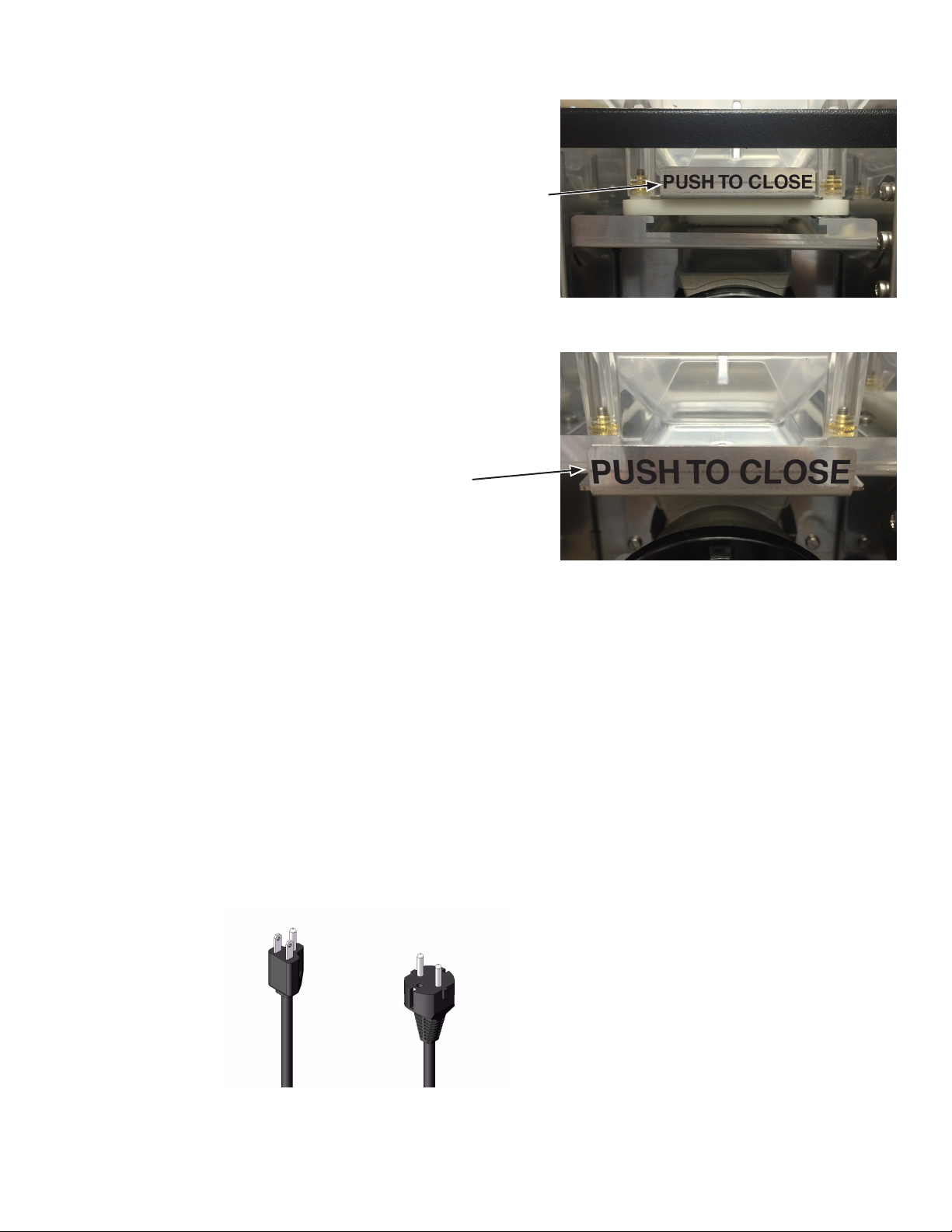
3. When the screen prompts ADD CLEANING TABLET, open
the dispenser door, and drop a cleaning table into the opening of the espresso brew chamber as shown.
Add cleaning
tablet here
SELECT MODE
RINSE CLEAN
1. SELECT SIZE
2. SELECT BEVERAGE
ADD CLEANING
TABLET NEXT
4. Close dispenser door and place a minimum 500ml container
under the dispense nozzles.
5. Press the button under NEXT.
20
52384.1 062217
Page 21

CLEANING - CLEAN CYCLE continued
6. When screen displays PRESS DISPENSE TO START, press any
beverage dispense button to begin cleaning cycle.
7. During the cleaning cycle, the screen with display CLEANING
CYCLE IN PROGRESS/PRESS TO STOP.
PRESS DISPENSE
TO START
CLEANING CYCLE
IN PROGRESS
PRESS ANY BUTTON
8. When the cleaning cycle is complete, screen will display SELECT MODE/ RINSE__ CLEAN.
9. Discard the waste water collected from the cleaning cycle.
10. Open the dispenser door, and place the NORMAL/PROGRAM/
RINSE switch in the NORMAL position.
TO STOP
SELECT MODE
RINSE CLEAN
21
52384.1 062217
Page 22

Weekly: Parts Washing and Sanitizing
1. Remove elbows from
all hoppers.
6. Rotate tab on mixing chamber base
further counter clock
wise, and remover
from shaft by pulling
straight out.
NOTE: Insure O-ring and
shaft seal are in place
during re-assembly.
2. Remove elbows from
right & left mixing
chambers, twisting
slightly to help release.
7. Remove dispense
hoses from dispense
nozzle assembly.
3. Rotate tab at bottom
of mixing chamber
bases counter clock
wise to release base.
8. Clean all parts removed in warm soapy
water. Use Bunn P/N
11685.0000 cleaning brush provided
to clean bores and
orifices. Rinse in cold
water.
4. Remove mixing
chambers by pulling
straight out.
9. Prepare one-gallon
(3.8 liter) of sanitizing solution with at
least 100 ppm of
available chlorine in
120°F (48.9°C) water. Soak all cleaned
parts in sanitizing solution for 5 minutes,
then allow to air dry.
5. Remove right frother
disk from shaft by
pulling straight out.
10. Rinse cleaning brush,
dip in sanitizing solution, and brush the
bore of both dispense
nozzles.
NOTE: Repeat this procedure for each nozzle
separately.
11. When reassembling
parts, be sure to align
arrow on frother disk
with flat on whipper
motor shaft, and rotate tab on whipper
base clock wise to
the vertical position
to lock mixing chamber.
22
52384.1 062217
Page 23

LOCKS/DISABLES
1. Open the door and place the NORMAL/PROGRAM/RINSE
switch in the PROGRAM position.
2. Use the Large Cup button to scroll to the LOCKS/DISABLES
screen, and press the button under “YES”.
LOCKS/DISABLES
EXIT YES
3. In the DISPENSE LOCKOUT screen, pressing the
button under YES will prevent the dispenser from
operation if the tanks are not at the minimum ready temperature requirement. Pressing the button under NO will allow
dispensing if the tank temperatures are below ready temperature requirement.
4. Press the Large Cup button to RINSE ALARM. Pressing the
button under YES will enable the rinse alarm. The screen
will display RINSE ALARM TIME. Use the buttons under (-)
and (+) to modify the rinse alarm time. If the time set since
the last rinse has been exceeded, a rinse required will be
displayed on the front door screen.
5. Press the Large Cup button to RINSE LOCKOUT.
Pressing the button under YES will disable the dispenser
once the RINSE ALARM TIME has expired. Running a rinse
cycle will reset the timer, and enable the dispenser to resume
normal operation.
DISPENSE LOCKOUT
NO EXIT YES
RINSE ALARM
NO EXIT YES
RINSE ALARM TIME
(-) 12hours (+)
RINSE LOCKOUT
NO EXIT YES
6. Press the Large Cup button to LOW HPR LOCKOUT. Pressing the button under YES will prevent espresso shots from
being prepared if the coffee bean hopper detects a low bean
level condition. Filling the bean hopper above the low level
will allow espresso brewing to resume.
23
LOW HPR LOCKOUT
NO EXIT YES
52384.1 062217
Page 24

ADJUSTMENTS
BEVERAGE DISPENSE TIME ADJUSTMENT:
1. Open the door and place the NORMAL/PROGRAM/RINSE switch in the PROGRAM position.
2. Use the Large Cup button to scroll to the SET BEVEREGE SZ screen, and press the button under “YES”.
3. Use the Large Cup button to access the beverage you wish to modify.
4. Under the beverage name, use the buttons under (-) and (+) to modify the dispense time for that beverage.
5. Press the LARGE CUP BUTTON after the time has been adjusted.
6. Place the NORMAL/PROGRAM/RINSE Switch in the NORMAL position, and press the center button to exit the
program mode.
HOPPER DISPENSE VOLUME ADJUSTMENT:
The powder throw for the powder products is pre-set from the factory. It can be checked and adjusted in
the field using this adjustment procedure.
1. Open the door and place the NORMAL/PROGRAM/RINSE switch in the PROGRAM position.
2. Remove the mixing chamber below the left hopper outlet elbow.
3. Press the Large Cup button until “STRENGTH ADJ?” menu, and press the button under “YES”.
4. The display will read LEFT HOPPER STR, referring to the left or hopper 1.
5. Press the Large Cup button to TEST LEFT HOPPER menu.
6. Tare a small cup on the digital scale, then hold the cup under the hopper outlet elbow, and press the espresso
button.
7. The hopper will dispense powder product into the cup for 10 seconds, then automatically stop.
8. Set the first dispense aside.
9. Repeat the process two more times, and average the three results to determine throw weight of the powder product.
10. To determine throw rate, divide average by 10 to determine the grams or ounces per second being dispensed.
11. To adjust hopper throw rate, press the Small Cup button and the screen will read LEFT HOPPER STR. Use the
buttons under the (-) or (+) to decrease or increase the hopper speed, as required.
12. Press the Large Cup button to TEST LEFT HOPPER menu, and retest the adjustment.
13. After hopper 1 is checked and adjusted, use the Large Cup button to move to MDLE HOPPER TEST. Remove the
right mixing chamber, and repeat steps 6 though 11 to test and adjust the middle, or second hopper.
14. Use the Small Cup button to move to “POWDER STRNGTH 2” screen to adjust speed for hopper 2, if required.
15. After hopper 2 is checked and adjusted, use the Large Cup button to move to TEST RT HOPPER. Repeat steps
6 though 11 to test and adjust the right, or third hopper.
16. Use the Up Arrow to move to RIGHT HOPPER STR screen to adjust speed for hopper 3, if required.
17. Reassemble the mixing chambers when the adjustments are complete.
18. Place the NORMAL/PROGRAM/RINSE Switch in the NORMAL position, and press to exit the program mode.
24
52384.1 062217
Page 25

ADJUSTMENTS - continued
GRINDER THROW WEIGHT ADJUSTMENT:
1. Open the door, and slide the espresso brew group lock to the left to unlock the brew group.
2. Tip the top of the brew group head towards the front of the machine to disengage from the espresso drive, then
remove brew group from the drive.
3. Place the NORMAL/PROGRAM/RINSE switch in the PROGRAM position.
4. Press the Large Cup button to the STRENGTH ADJUST menu, then press the button under YES.
5. Press the Large Cup button to TEST SM GRINDTM.
6. Place a small container on a scale, and tare container.
7. Hold the container under the grinder chute, and press any beverage dispense button.
8. Grinder will run for the time set for a small (single shot) espresso, then stop.
9. Repeat several times, and average the weight.
10. To change the weight, press the Small Cup button to SM ESP GRIND TIME.
11. Us the buttons below the (-) and (+) button to increase or decrease the grind time.
12. Press the Large Cup button to TEST SM GRIND to test new grind time.
13. Press the Large Cup button to TEST LG GRIND to test the large (double shot) grind weight.
14. Press the Small Cup button to LF ESP GRIND TIME to adjust the grind time for a large (double shot) espresso,
if required.
15. After the grind adjustments have been tested and adjusted, place the NORMAL/PROGRAM/RINSE Switch in the
“RUN” position, and press to exit the program mode.
16. Reinstall the espresso group head back onto the espresso drive.
GRINDER PARTICLE SIZE ADJUSTMENT:
The particle size of the ground coffee can be adjusted for optimal brewing of the espresso.
1. Turn knob counterclockwise to increase the particle size of the
ground coffee (see Figure 1.)
2. Turn the knob clockwise to decrease the particle size of the
ground coffee. CAUTION! If there is ground coffee in the grinder,
this adjustment should only be made while the grinder is running.
Use STRENGTH ADJUST, TEST SM or LG GRIND functions to
operate the grinder for adjusting to a finer grind.
25
Figure 1
52384.1 062217
Page 26

DOOR SAFETY INTERLOCK
The dispenser is equipped with a door interlock safety switch,
which prevents the operator from being exposed to the moving
parts of the espresso brewer if the door is open.
The switch may be overridden by a qualified service technician by inserting the service key, (BUNN PN 51953.0001) into
the opening of the mixing chamber panel, then turning 90° as
shown in Figure 2.
Service Key
DRAINING THE HOT WATER TANKS – to be performed by quali-
fied service personnel only!
1. Open the door and place the NORMAL/PROGRAM/RINSE switch in the
PROGRAM position.
2. Close the door and place a minimum two liter container under the dispense nozzles.
3. Press the Large Cup button until the screen reads DIAGNOSTICS.
4. Press, in sequence, buttons 3, 7, 4 and 1. See diagram below for button
number designations.
5. The screen will display SYSTEM WET TEST. Press the button under YES.
6. Press the button under COOL ESP TANK.
7. Press the button under START in the COOL ESP TANK screen.
8. The pump will begin running, and hot water will dispense into the container. After 4 minutes, the pump will automatically stop.
9. In the ESP TANK COOL? screen, press the button under YES.
NOTE: Dispenser must be disconnected from the power source in steps
10 through 24.
10. Immediately disconnect the dispenser from the power source, and water
supply.
11. Let the water in the soluble tank cool before draining.
12. Remove left side panel.
13. Pull the drain tube out of the dispenser and direct it into a drain or a
container large enough to hold the volume of water in the tank, approx 6
liter (1.5 gallon).
14. Remove the plug from end of tube.
15. After the tank has drained, replace the plug in the end of the tube.
16. Remove the tube from the connector in the bottom of the espresso tank.
17. Swivel the tube towards the outside of the machine.
18. Empty the container used to capture the hot water from the tank, and
place it on the right side of the machine.
19. Insert a 6mm OD tube into the bottom tank fitting, place the other end
into the container.
20. Use a 4mm hex wrench to loosen the plug on the top of the espresso
tank, until the tank begins to drain.
21. After the tank is drained, retighten the plug.
22. Remove the drain tube from the bottom tank fitting.
23. Rotate the fitting towards the inside of the tank. Compressing the release
sleeve on the fitting, fully insert the pump tube.
24. Replace the left and right side panels.
Figure 2
Figure 1
1
3
4
7
Figure 2
26
52384.1 091217
Page 27

PASSWORD PROTECTION
In the PROGRAMMING MENU, there are two levels
of password protection available:
PASSWORD 1 Protects all program menu settings.
PASSWORD 2 Allows monitoring and changes to the tank
temperature and strength adjust settings, but
protects all other settings.
PASSWORD 1
1. To enter PASSWORD 1: Open the door and place the NORMAL/
PROGRAM/RINSE switch in the PROGRAM position. (Figure 1).
2. In the PROGRAMMING MENU the “ENTER PASSWORD 1” screen
will display after the “APPLICATION/SW VERSION 00.##” screen
(refer to “PROGRAM MENU” flow chart).
3. The unit is shipped from the factory with a default password
setting of 0000.
4. To set PASSWORD 1: The “SET PASSWORD 1” screen will
display after the “ENTER PASSWORD 1” screen. Use the (-) and
(+) buttons to set any numerical password desired, from 0000 to
9999. Password is set one digit at a time.
PASSWORD 2
1. To enter PASSWORD 2: Open the door and place the NORMAL/
PROGRAM/RINSE switch in the PROGRAM position.
2. In the PROGRAMMING MENU the “ENTER PASSWORD 2”
screen will display after the “STRENGTH ADJUST”menu (refer to
“PROGRAM MENU” flow chart).
3. The unit is shipped from the factory with a default password
setting of 0000.
4. To set PASSWORD 2: The “SET PASSWORD 2” screen will
display at the end of the “LOCKS/DISABLES” menu (refer to
“PROGRAM MENU” flow chart). Use the (-) and (+) buttons to set
any numerical password desired, from 0000 to 9999. Password
is set one digit at a time.
Figure 1
SET PASSWORD 1
(-) 0000 (+)
Use these buttons to enter
or set the password
Figure 2
27
52384.1 091217
Page 28

GLOSSARY
TANK TEMP XXX°
(-) EXIT (+)
READY TEMP XXX°
(-) EXIT (+)
ESPRSO TEMP XXX°
(-) EXIT (+)
ESPRSO READY XXX°
(-) EXIT (+)
STRENGTH ADJUST
EXIT YES
CALIBRATION
EXIT YES
SET BEVERAGE SZ
EXIT YES
SET ESPRSO SHOTS
EXIT YES
LOCKS/DISABLES
EXIT YES
DIAGNOSTICS
EXIT YES
Adjust soluble tank temperature
(190° F maximum)
Adjust minimum soluble tank ready temperature for lockout (185° maximum)
Set espresso tank temperature.
Set espresso tank ready temperature.
Tank temp. must reach this to enable
brewing if brew lockout is set.
Takes you to the STRENGTH ADJUST
sub-menu to adjust soluble hopper
speeds and grinder times.
Takes you to the CALIBRATION
sub-menu.
Takes you to the SET BEVERAGE
SIZE sub-menu to adjust beverage
size.
Takes you to the SET ESPRESSO
SHOTS sub-menu to set up espresso
shots.
Takes you to the LOCK/DISABLES
sub-menu.
Takes you to the DIAGNOSTICS menu
to test components.
AUGER DELAY
(-) .50 sec (+)
WHIPPER DELAY
(-) .00 sec (+)
CAL HOT WATER
PRESS DISPENSE
CAL LFT PWDR VLV
PRESS DISPENSE
CAL RT PWDR VLV
PRESS DISPENSE
PUMP START DELAY
(-) .# sec (+)
ESP THRESHOLD
(-) ### (+)
PSTN HOME THRESOLD
(-) ### (+)
Delays the start of the hopper motors after dispense valve opens. This
prevents soluble powder from entering
mixing chamber ahead of hot water.
This delays the start of the whipper
motors after the dispense valve opens.
Pressing any dispense button opens
the hot water valve for ten seconds.
This allows the valve to be adjusted for
the proper flow rate.
Pressing any dispense button opens
the left hot water valve for ten
seconds. This allows the valve to be
adjusted for the proper flow rate.
Pressing any dispense button opens
the right hot water valve for ten
seconds. This allows the valve to be
adjusted for the proper flow rate.
This delays the start of the espresso
pump after the espresso valve opens.
This sets the current level at which
the piston sees, to signal the motor to
shut down in the wipe position.
This sets the current level at which
the piston sees, to signal the motor to
shut down in the home position.
FACTORY DEFAULTS
NO YES
LEFT HOPPER STR
(-) ## (+)
TEST LEFT HOPPER
PRESS DISPENSE
SM ESP GRIND TIME
(-) #.# sec (+)
TEST SM GRIND
DISPENSE TO TEST
SELECT UNITS
ENG EXIT METRIC
0 REFILL 155
(-) EXIT (+)
Takes you to the FACTORY DEFAULTS
sub-menu to enable restoring factory
defaults.
Use +/- buttons to increase or decrease
powder hopper speed. This menu
repeats for middle and right hopper.
Pressing any dispense button will run
hopper for 10 seconds, at speed set in the
menu above. This allows a catch test.
Pressing any dispense button will run
grinder for the small espresso programmed time. This allows a catch test.
Menu repeats for large espress grind time.
Pressing any dispense button will run
grinder for the small espresso programmed
time. This allows a catch test. Menu
repeats for large espresso grind time.
Allows applicable data to be displayed in
English or Metric units.
Sets threshold for refill probe on soluble
water tank. Allows adjustment for different
water conditions.
CAL BEAN HOPPER
EXIT YES
PRE-HEAT ESP GRP
NO EXIT YES
SET PRE-HEAT TIME
(-) ###min (+)
ESPR TANK: ###F
PWDR TANK: ###F
This calibrates the photo sensor on
the bean hopper by detecting the ambient light with the hopper empty, then
setting a threshold for signaling when
the hopper is empty.
This asks if you want to enable
pre-heating of the espresso group, if
espresso has not been brewed within
“X” amount of time. For espresso
shots only - not for specialty drinks.
Sets the amount of time (in minutes),
that if exceeded, will automatically go
into pre-heat routine, if an espresso
shot is selected to be dispensed.
Live temperature display, or probe
fault codes.
28
52384.1 062217
Page 29

GLOSSARY - continued
SET DRAIN TIME
(-) .# sec (+)
SM COFFEE WHITE
(-) #.# sec (+)
LG COFFEE WHITE
(-) #.# sec (+)
SM ESP GRIND TIME
(-) #.# sec (+)
SM DRY TAMP %
(-) ### (+)
SM PREINFUSION
(-) #.# sec (+)
SM DWELL TIME
(-) #.# sec (+)
SM BREW VOLUME
(-) ### (+)
DISPENSE LOCKOUT?
NO EXIT YES
RINSE ALARM?
NO EXIT YES
RINSE ALARM TIME
(-) 12 Hours (+)
RINSE LOCKOUT?
NO EXIT YES
Set the amount of time after the hot
water has completely pumped into
the brew chamber, for the pre-heat
cycle so that the drain valve is on to
drain the chamber.
Sets the dispense time (in seconds)
for a small COFFEE WHITE beverage.
Menu repeats for nine other
beverages.
Sets the dispense time (in seconds)
for a large COFFEE WHITE beverage.
Menu repeats for nine other
beverages.
Sets grinder run time for small
espresso. Repeat of menu in
STRENGTH ADJUST sub menu.
Menu repeats for large espresso.
Sets the percentage of full voltage
to piston motor for tamping the
dry puck. Menu repeats for large
espresso.
Sets the espresso pump run time for
pre-infusion of tamped coffee. Zero
seconds for no pre-infusion. Menu
repeats for large espresso.
Sets the dwell time (in seconds)
between pre-infusion and the start of
the espresso pump for final brewing.
Menu repeats for large espresso.
Sets the brew volume for a small
espresso by flow count from flow
meter. Menu repeats for large
espresso.
Enables locking out beverage
dispensing if either tank is not at or
above the ready temperature.
Asks if you want to set an alarm, if a
rinse cycle has not been run for “X”
amount of time since the last rinse
cycle.
Sets the number of hours since
the last rinse cycle was run before
signaling a rinse is needed.
Enabling prevents the dispensing of
any beverage until a rinse cycle is
completed.
TEST SWITCHES
UseSwitchToTest
TEST REFILL
EXIT YES
TEST LEFT AUGER
DISPENSE TO TEST
TEST MDL AUGER
DISPENSE TO TEST
TEST RIGHT AUGER
DISPENSE TO TEST
TEST LEFT WHIPR
DISPENSE TO TEST
TEST RT WHIPR
DISPENSE TO TEST
TEST HOT WATER
DISPENSE TO TEST
TEST LFT PWDR VLV
DISPENSE TO TEST
TEST RT PWDR VLV
DISPENSE TO TEST
TEST DRAIN VALVE
DISPENSE TO TEST
TEST PUMP N VALV
DISPENSE TO TEST
TEST ESPRESSO VALV
DISPENSE TO TEST
Pressing any switch on the door will
display the switch number on the LCD
to confirm function. This is a momentary switch function.
Pressing any switch on the door will
activate the soluble tank refill valve.
This is a momentary switch function.
Pressing any switch on the door will
activate the left hopper auger motor.
This is a momentary switch function.
Pressing any switch on the door will
activate the middle hopper auger
motor. This is a momentary switch
function.
Pressing any switch on the door will
activate the right hopper auger motor.
This is a momentary switch function.
Pressing any switch on the door will
activate the left whipper motor. This is
a momentary switch function.
Pressing any switch on the door will
activate the right whipper motor. This
is a momentary switch function.
Pressing any switch on the door will
activate the hot water valve. This is a
momentary switch function.
Pressing any switch on the door will
activate the left powder hot water
valve. This is a momentary switch
function.
Pressing any switch on the door will
activate the right powder hot water
valve. This is a momentary switch
function.
Pressing any switch on the door will
activate the drain valve in the brew
group. This is a momentary switch
function.
Pressing any switch on the door
will activate the solenoid pump and
espresso valve. This is a momentary
switch function.
Pressing any switch on the door will
activate the espresso valve. This is a
momentary switch function.
LOW HPR LOCKOUT?
NO EXIT YES
Enabling prevents espesso brewing
if a low bean hopper condition is
detected.
TEST SOLUBLE FAN
DISPENSE TO TEST
NOT PRESENT
29
PUCK BIN
Pressing any switch on the door will
activate the soluble fan. This is a
momentary switch function.
Signals puck bin status.
52384.1 062217
Page 30

GLOSSARY - continued
TEST GRINDER
DISPENSE TO TEST
TEST FLOW METER
FLOW METER: 0
TEST PISTON
DOWN 140 UP
TEST SIEVE
OPEN 0 CLOSE
PUCK BIN
NO EXIT YES
PUCK CAPACITY
(-) ### (+)
STATISTICS
EXIT YES
ODOMETER
#########
SM LIFETM COUNTS
SELECT BEVERAGE
LG LIFETM COUNTS
SELECT BEVERAGE
Pressing any switch on the door will
activate the coffee grinder motor.
This is a momentary switch function.
Note: Bean hopper must be in place.
Pressing any switch on the door
will activate the espresso pump and
espresso water valve. Flow counts
will increment on the LCD display
This is a momentary switch function.
Pressing the button below the
“DOWN” or “UP” on the LCD display
will activate the appropriate piston
action.
Pressing the button below the “OPEN”
or “CLOSE” on the LCD display will
activate the appropriate sieve head
action.
Pressing the button below the “YES”
will enable the puck bin counting
functionality, whereas selecting “NO”
sets up the machine for thru-counter
operation.
Sets the amount of pucks the bin can
hold before it needs to be emptied,
and is only allowed to be set if the
puck bin feature is currently enabled.
Takes you to the statistics sub-menu
so that you can look at cup counts.
Total overall drinks dispensed by this
machine in its life time, non-resettable.
Drinks dispensed per beverage of
the small cup counts size. Press and
release a dispense button to see the
number of times that recipe has been
dispensed.
Drinks dispensed per beverage of
the large cup counts size. Press and
release a dispense button to see the
number of times that recipe has been
dispensed.
RESET CUP COUNTS
NO YES
SELECT LANGUAGE
(-) ENGLISH (+)
APPLICATION
SW VERSION 00.##
BOOTLOADER
SW VERSION 00.##
PCPAP MODULE
(-) ENGLISH (+)
LCD MODULE
2 X 16
ENTER PASSWORD 1
(-) 0000 (+)
SET PASSWORD 1
(-) 0000 (+)
ENTER PASSWORD 2
(-) 0000 (+)
SET PASSWORD 2
(-) 0000 (+)
ENERGY SAVER?
NO EXIT YES
Cup counts (all) can be reset.
Allows user to scroll through available
languages. Default is English.
Identifies current software version in
main circuit board.
Identifies bootloader software version.
Identified current software version in
PCAP module.
Identifies LCD module installed in this
machine.
Requires level 1 password to be
entered to access remaining program
menus.
Used to set level 1 password. Password may be any number from 0000
to 9999.
Requires level 2 password to be
entered to access remaining program
menus.
Used to set level 2 password. Password may be any number from 0000
to 9999.
Enables energy saver mode to save
energy in off hours.
SM RESETABLE CNTS
SELECT BEVERAGE
LG RESETABLE CNTS
SELECT BEVERAGE
Drinks dispensed per beverage of
the small cup counts size. Press and
release a dispense button to see the
number of times that recipe has been
dispensed. Count can be reset.
Drinks dispensed per beverage of
the large cup counts size. Press and
release a dispense button to see the
number of times that recipe has been
dispensed. Count can be reset.
30
52384.1 062217
Page 31

PROGRAMMING THE DISPENSER
The following function screens are in order of appearance.
Each screen will have instructions on how to access, and
the procedures to program the various functions of the
dispenser. To enable programming, place the “NORMAL/
PROGRAM/RINSE” switch in the “PROGRAM” position.
IMPORTANT PROGRAMMING NOTES -
READ CAREFULLY
To exit the programming mode at any time, press and
release the exit (center) pad located on the front switch
panel. The display will return to the PROGRAM HOME
SCREEN.
If none of the five programming switches are pressed
within 90 seconds during the setup of the dispenser, the
programming of the function screen that is being set will
be exited and the display will return to the PROGRAM
HOME SCREEN.
NOTE: To change the display language, see page 13
of this manual.
PROGRAMMING SWITCHES
Using the menu-driven display (MAIN SCREEN) on the
front of dispenser, the operator has the ability to alter or
modify various functions of the dispenser. This allows
for precise dispensing of various flavors of powdered
products.
Programming of dispenser is achieved by entering a
certain function, then, by use of programming switches,
the operator can customize the dispensing process to
their specifications.
1. SELECT SIZE
ABCDE
A. Enter program mode and advance to next menu
B. Increment display value positive
C. Exit program mode / Stop Dispense Cycle
D. Increment display value negative
E. Return to previous menu
To access the programming mode, and to scroll through
different function screens, the programming switches
shown are used. There are five switches that will be used
for setup of the dispenser.
NORMAL/PROGRAM/RINSE switch:
NORMAL: Allows all dispenser functions. Must be in this
position for dispensing.
PROGRAM: Allows access to program menus using touch
pad and LCD screen.
RINSE: Pressing dispense button on front door will
dispense dilution water and power whipper motor for ten
seconds.
31
P4368
52384.1 091217
Page 32

PROGRAMMING MENU
To access the Programming Menu open the door and place the
NORMAL/PROGRAM/RINSE switch in the PROGRAM position.
MAIN MENU
Strength Adjust
sub-menu
LEFT HOPPER STR
(-) ## (+)
PROGRAM MODE
PRESS TO ENTER
APPLICATION
SW VERSION 00.##
ENTER PASSWORD 1
(-) 0000 (+)
SET PASSWORD 1
(-) 0000 (+)
ESPR TANK XXX°
PWDR TANK XXX°
TANK TEMP XXX°
(-) EXIT (+)
continue to
“Software
Versions”
sub-menu
(see page 26)
(see page 26)
STRENGTH ADJUST
EXIT YES
ENTER PASSWORD 2
(-) 0000 (+)
CALIBRATION
EXIT YES
SET ESPRSO SHOTS
EXIT YES
RECIPE SETUP?
EXIT YES
LOCKS/DISABLES
EXIT YES
continue to
“Strength Adjust”
sub-menu
(see page 26)
continue to
“Calibration”
sub-menu
continue to
“Set Espresso
Shots”sub-menu
continue to
“Build A Beverage”
sub-menu
TEST LEFT HOPPER
PRESS DISPENSE
MDLE HOPPER STR
(-) ## (+)
TEST MDLE HOPPER
PRESS DISPENSE
RIGHT HOPPER STR
(-) ## (+)
TEST RT HOPPER
PRESS DISPENSE
READY TEMP XXX°
(-) EXIT (+)
ESPRSO TEMP XXX°
(-) EXIT (+)
ESPRSO READY XXX
(-) EXIT (+)
Typical Button Functions
Back
Exit
Forward
Sub-menu
DIAGNOSTICS
EXIT YES
STATISTICS
EXIT YES
FACTORY DEFAULTS
NO YES
Exit to
“Main Menu”
Home
continue to
“Locks/Disables”
sub-menu
continue to
“Diagnostics”
sub-menu
continue to
“Statistics”
sub-menu
continue to
“Factory Defaults”
sub-menu
32
SM ESP GRIND TIME
(-) #.# sec (+)
TEST SM GRIND
DISPENSE TO TEST
LG ESP GRIND TIME
(-)#.# sec(+)
TEST LG GRIND
DISPENSE TO TEST
To Main Menu Item:
“Enter Password 2”
52384.1 091217
Page 33

PROGRAMMING MENU’S (cont.)
Calibration Sub-Menu
SELECT UNITS
ENG EXIT METRIC
0 REFILL 155
(-) EXIT (+)
AUGER DELAY
(-) .50 sec (+)
WHIPPER DELAY
(-) .00 sec (+)
CAL HOT WATER
PRESS DISPENSE
Software Version
Sub-Menu
BOOTLOADER
SW VERSION 00.##
PCAP MODULE
SW VERSION 00.##
LCD MODULE
2X16
To Menu Item:
“Enter Password 1”
Set Espresso Shots
Locks/Disables
Sub-Menu Sub-Menu
SM ESP GRIND TIME
(-) #.# sec (+)
SM DRY TAMP %
(-) #.# sec (+)
SM PREINFUSION
(-) #.# sec (+)
Only is
shown
if the
alarm is
SM DWELL TIME
(-) #.# sec (+)
SM BREW VOLUME
(-) #.# sec (+)
“YES”
DISPENSE LOCKOUT?
NO YES
RINSE ALARM
NO YES
RINSE ALARM TIME
(-)12 hours(+)
RINSE LOCKOUT?
NO YES
LOW HPR LOCKOUT
NO YES
CAL LFT PWDR VLV
PRESS DISPENSE
CAL RT PWDR VLV
PRESS DISPENSE
PUMP START DELAY
(-) .# sec (+)
ESP THRESHOLD
(-) ### (+)
PSTN HOME THRESHOLD
(-) ### (+)
#### BN HPER ###
(-) EXIT (+)
PRE-HEAT ESP GROUP
NO EXIT YES
SET PRE-HEAT TIME
(-) ### (+)
SET DRAIN TIME
(-) .# sec (+)
LG ESP GRIND TIME
(-) #.# sec (+)
LG DRY TAMP
(-) #.# sec (+)
LG PREINFUSION
(-) #.# sec (+)
LG DWELL TIME
(-) #.# sec (+)
LG BREW VOLUME
(-) ### (+)
(see page 13)
(see page 26)
PUCK BIN
NO EXIT YES
PUCK CAPACITY
(-) ### (+)
ENERGY SAVER?
NO YES
SET PASSWORD 2
(-) 0000 (+)
To Menu Item:
“Diagnostics”
To Menu Item:
“Set Espresso Shots”
To Menu Item:
“Recipie Setup?”
33
52384.1 091217
Page 34

PROGRAMMING MENU’S (cont.)
TEST SWITCHES
UseSwitchToTest
TEST POWDER HTR
YES
TEST ESPRSO HTR
YES
TEST REFILL
EXIT YES
TEST LEFT AUGR
DISPENSE TO TEST
Diagnostics
TEST LFT PWDR VLV
DISPENSE TO TEST
TEST RT PWDR VLV
DISPENSE TO TEST
TEST DRAIN VALVE
DISPENSE TO TEST
TEST PUMP N VALV
DISPENSE TO TEST
Factory Defaults
Sub-Menu
WILL REPLACE ALL
DISPENSE SETUPS
ARE YOU SURE
NO YES
Exit to Home Screen
Statistics
Sub-MenuSub-Menu
ODOMETER
##########
SM LIFETM COUNTS
SELECT BEVERAGE
LG LIFETM COUNTS
SELECT BEVERAGE
SM RESETABLE CNTS
SELECT BEVERAGE
LG RESETABLE CNTS
SELECT BEVERAGE
TEST MDL AUGR
DISPENSE TO TEST
TEST RIGHT AUGR
DISPENSE TO TEST
TEST LEFT WHIPR
DISPENSE TO TEST
TEST RT WHIPPER
DISPENSE TO TEST
TEST HOT WATER
DISPENSE TO TEST
TEST ESPRESO VALVE
DISPENSE TO TEST
TEST SOLUBLE FAN
DISPENSE TO TEST
PUCK BIN
NOT PRESENT
TEST GRINDER
DISPENSE TO TEST
TEST FLOW METER
FLOW METER: 0
depending on puck bin state
alt:
PUCK BIN
PRESENT
TEST PISTON
DOWN 140 UP
TEST SIEVE
OPEN 0 CLOSE
RESET CUP COUNTS
NO YES
THIS WILL CLEAR
ALL CUP COUNTS
ARE YOU SURE?
NO YES
To Menu Item:
“Factory Defaults”
To Menu Item:
34
“Statistics”
52384.1 091217
Page 35

PROGRAMMING MENU’S (cont.)
Build A Beverage - Standard Menu
NOTE: Press and release
right switch to advance to
next menu.
“if single touch mode active” “if multi touch mode active”
SETUP SW 1 RECIPE
NO YES
SWITCH 1 RECIPE
(-) CAPPUCCINO (+)
SW 1 DRINK SIZE
SMALL LARGE
Build A Beverage Sub-Menu
Standard Menu
RECIPE SETUP?
EXIT YES
USER SELECT MODE
SINGLE MULTI
If No, move to next recipe.
If Yes, move into current
recipe. Switch 1’s associated
LED turns ON.
Any preset recipe is selectable, or they can also select
“DISABLE” to turn off key.
and can select CUSTOM to
build their own.
(see page 12)
Select Single Touch or Multi
Touch
Multi touch screens on the
left, their replacements for
single touch on right.
Note: The flashing text is the
active/selected item.
SETUP SW 1 RECIPE
NO YES
SWITCH 1 RECIPE
(-) CAPPUCCINO (+)
SW 1 SMALL TM
(-) ##.# (+)
If No, move to next recipe.
If Yes, move into current
recipe. Switch 1’s
associated LED turns ON.
Any preset recipe is
selectable, or they can
also select “DISABLE” to
turn off key. and can select
CUSTOM to build their
own.
SW 1 DISPENSE TM
(-) ##.# (+)
DO THIS FOR ALL 10 SWITCHES
Goes back to “SETUP SW 1
RECIPE? for the next switch
in the sequence..
(continued on next page)
SW 1 LARGE TM
(-) ##.# (+)
DO THIS FOR ALL 10 SWITCHES
35
Goes back to “SETUP SW 1
RECIPE? for the next switch
in the sequence..
52384.1 091217
Page 36

PROGRAMMING MENU’S (cont.) - Build A Beverage - Custom Beverage
Build A Beverage
RECIPE SETUP?
EXIT YES
USER SELECT MODE
SINGLE MULTI
SETUP SW 1 RECIPE
NO YES
SWITCH 1 RECIPE
(-)CUSTOM(+)
SW 1 SMALL TM
(-) ##.# (+)
Build A Beverage Sub-Menu (continued)
Select Single Touch or Multi
Touch
Multi touch screens on the
left, their replacements for
single touch on right.
Optional way to skip past
a lengthy setup process.
Switch 1’s associated LED
turns on.
Recipe 1 thru 10 selectable
can also select “Disable” to
turn off key.
SW DRINK SIZE
SMALL LARGE
This picks the shot size for
single touch as well as for
the cup count.
(see page 12)
HOPPER LEFT STR
(-) ### (+)
HOPPER RIGHT STR
(-) ### (+)
DO THIS FOR ALL 10 SWITCHES
NOTE: Press and release
right switch to advance
to next menu.
Note: 1st ingredient speed
can be from 15 to 100 RPM,
however, would not appear if
dilution was selected.
Note: 2nd ingredient speed
can be from 15 to 100 RPM,
however, would not appear if
dilution was selected.
Goes back to “Setup SW 1
Recipe?” for the next switch
in the sequence
SW 1 LARGE TM
(-) ##.# (+)
ESPRESSO SHOT?
NO YES
1ST POWDER / DIL
(-)
HPR LEFT
2ND POWDER / DIL
(-)
HPR RIGHT
HPR LEFT PORTION
(-) ##% (+)
(+)
(+)
SW 1 DISPNSE TM
(-) ##.# (+)
Dispense time cannot be set below
minimum time (ie. 5.0 sec.)
Does beverage need an
espresso shot? If YES, it will
use the corresponding size set
for single touch or for the size
button selected in Multi.
Options are for three hoppers or dilution. Cannot
choose “NONE” here as if wanting an espresso, only
can pick that from the “Switch # Recipe” screen.
This option comes up as the first item from Left to
Right of a Multi-ingredient drink when reloaded.
Items selected on the previous screen are not available on this one, however, the option for “None” is
now available.
This option is available if two items have been selected, the value must be between 15% and 85%. The
second item will be 100% minus value of item one.
Used for 1st ingredient selection
Used for 2nd ingredient selection
Used for selecting portion of
1st ingredient selection
36
52384.1 091217
Page 37

ELECTRICAL SCHEMATIC
37
52384.1 062217
 Loading...