

Page 1

INSTALLATION MANUAL
4BANK 6POSITION CHIP
Vehicle Application Part#
F250-F350 7.3L ’94-’97 Automatic Transmission Ford Power Stroke 41611
F250-F350 7.3L ’94-’97 Standard Transmission Ford Power Stroke 41612
F250-F350 7.3L Early ‘99 Automatic Transmission Ford Power Stroke 41613
F250-F350 7.3L Early ’99 Standard Transmission Ford Power Stroke 41614
F250-F350 7.3L ’99.5-’01 Automatic Transmission Ford Power Stroke 41615
F250-F350 7.3L ’99.5-’01 Standard Transmission Ford Power Stroke 41616
F250-F350 7.3L ’02-’03 Automatic Transmission Ford Power Stroke 41617
F250-F350 7.3L ’02-’03 Standard Transmission Ford Power Stroke 41618
Page 2

TABLE OF CONTENTS
INTRODUCTION/BILL OF MATERIALS ..................................................................PG 2
INSTALLATION STEPS...................................................................................PGS 49
94-’97 Installation
Removal of ECU..................................................................................................Pg 4
ECU Disassemble................................................................................................Pg 5
Installing 6 Position Chip ...................................................................................Pg 6
Installing Switch................................................................................................Pg 7
Early ’99-‘03 Installation
Removal of ECU....................................................................................................Pg 8
ECU Disassemble ...............................................................................................Pg 9
Installing 6 Position Chip..................................................................................Pg 10
Installing Switch ..............................................................................................Pg 11
Switch Operation.........................................................................................Pg 12
TROUBLESHOOTING .......................................................................................PG 13
WARRANTY & DISCLAIMER .............................................................................PG 14
TABLE OF CONTENTS
TROUBLESHOOTING:
Please review the Troubleshooting section on page 13 before
calling technical support to cover most common issues.Technical support is available by calling 866-bullydog (866-285-
5936).
1
Page 3
INTRODUCTION
Welcome to the world of increased power, performance and economy brought to you by the leader in performance, Bully Dog Technologies. This set of instructions outlines how to install and operate the 6 Position Chip
for the 7.3L Ford Power Stroke. The 6 Position Chips have been specially designed by the engineers at Bully Dog
to add additional horsepower and economy to the 7.3L Power Stroke.
Note: This instruction set and the included 6 Position chip are made for the ’94-’03 7.3L Ford Power Stroke. This chip
will not work on any other vehicle other than the stated make, model and year. Officially there were no ’98 model Power
Stroke vehicles produced by Ford, these vehicles are referred to as early ’99 vehicles.
IMPORTANT: Performance Chips must always be removed before taking the vehicle in for any kind of service, as it
may interfere with diagnostic tools.
IMPORTANT: DISCONNECT THE BATTERY BEFORE YOU BEGIN INSTALLATION
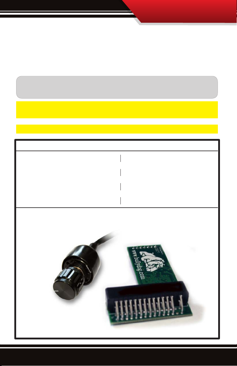
BILL OF MATERIALS
1. 6 Position Chip
2. 6 Position Switch
INTrOduCTION
TOOLS NEEDED
5.5mm Wrench or Socket
7mm Wrench or Socket
10mm Wrench or Socket
13mm Wrench or Socket
5/16” Allen Wrench
Sharp Knife or Razor Blade
Drill & 13/32” Drill Bit
Scotch Bright Pad
1.
2
Page 4
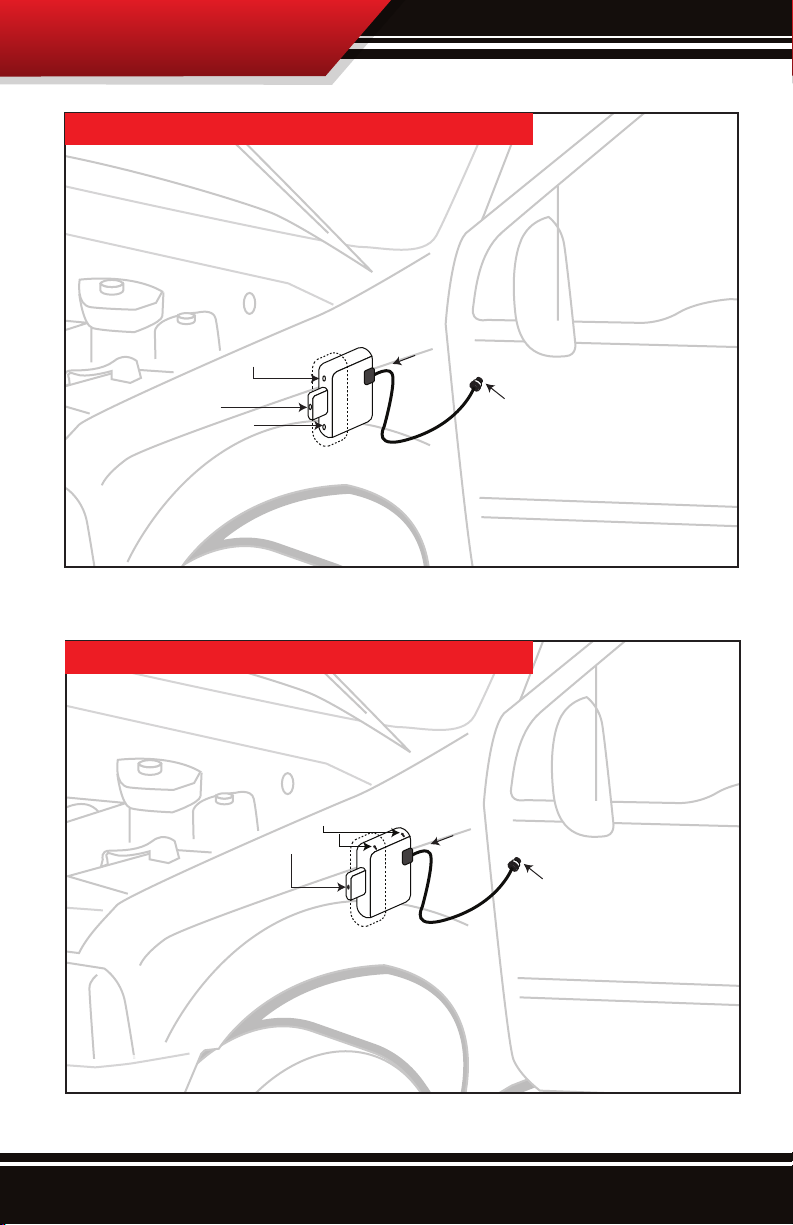
INSTALLATION STEPS
‘94’97 7.3L 6 POSITION CHIP
Ford ECU
10mm Nut
10mm Bolt
10mm Nut
(Firewall)
EARLY ’99’03 7.3L 6 POSITION CHIP
7mm Bolts
10mm Bolt
6 Position Chip
Ford ECU
6 Position Switch
6 Position Chip
6 Position Switch
(Firewall)
3
Page 5
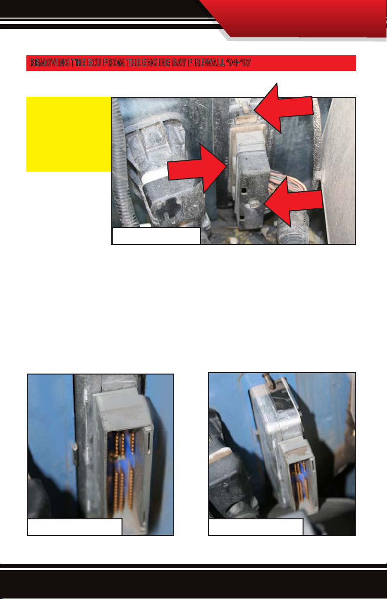
REMOVING THE ECU FROM THE ENGINE BAY FIREWALL ‘94‘97
In these steps you will remove the ECU from the firewall.
INSTALLATION STEPS
IMPORTANT: The steps
on this page are for
’94-’97 model vehicles.
If your vehicle is not a
’94-’97 skip the steps on
this page.
ECU
ECU on ‘94-’97 vehicles
1. Disconnect the battery.
2. Locate the back side of the ECU on the firewall closest to the wheel-well in the engine bay.
3. There is a 10mm bolt that needs to be removed from the back side of the ECU. The 10mm bolt is located in the center of the
housing.
4. Remove 10mm nuts that hold the ECU in place at the top and bottom of the ECU seal.
5. Slide the ECU out from the firewall.
10 MM Bolt
10 MM Bolt
ECU with Seal Removed
ECU pulled out half way
4
Page 6

INSTALLATION STEPS
DISASSEMBLE ECU TO CLEAN CONTACT POINTS ’94’97 VEHICLES
In these steps you will disassemble the ECU and clean the contact points.
IMPORTANT: The steps on this page are for ’94-’97 model vehicles. If your vehicle is not a ’94-’97 skip the steps on this page.
1. With the ECU laid on a at service, remove
six 5.5 mm bolts on the top half of the ECU.
2. Remove the top cover.
3. Gently remove the bottom cover as well.
4. Locate the contact point where the 6 Position chip will plug in.
NOTE: Most initial issues with the chip not working after being plugged in are caused because the contact
points were not clea n enough. A solid connection between the 6 Position Chip and the contact points is
required in order for the chip to function correctly. The best way to clean the contact points is to scrape the
silicon with a sharp knife or razor blade. Then take a nylon pad such as a Scotch bright pad to remove the
remainder of the silicon so that the copper connections are exposed.
5
5. Clean both the top and bottom of the contact points. Ensure that the pins on the ECU
are showing copper.
Page 7

INSTALLATION STEPS
INSTALLING THE 6 POSITION CHIP & SWITCH ON
’94’97 VEHICLES
In this steps you will route the switch into the cab and
plug the 6 Position Chip into the ECU.
IMPORTANT: The steps on this page are performed on ’94-’97
vehicles only. If your vehicle is not a ’94-’97 skip this page.
6 Position Chip
1. With the contact points clean, the 6 Position Chip can now be
installed onto the ECU. Gently work the 6 Position Chip onto the connector. You may have to work it side to side in order to
slide it completely onto the connector.
Removal of the Kick Plate Kick Plate Removed
ECU
2. Ensure that the connections are solid with both the chip as well as the switch.
3. The switch now needs to be routed into the cab. To do so, the kick plate located inside the cab by the driver’s
side door needs to be removed. To remove the kick plate, remove one screw in the door’s molding and a large
plastic rivet that is located in the center of the kick plate.
4. With the kick plate removed and the ECU removed you should be able to see through the rewall into the
engine bay. Take the ECU inside the engine bay and rst route the switch through the ECU housing and then
reinstall the ECU back in it’s housing.
5. Reverse the removal process and put the seal back in place and reconnect the cabling. Leave the kick plate
o until you have the switch installed.
6
Page 8

INSTALLATION STEPS
INSTALL THE 6 POSITION SWITCH EARLY ’94‘97
In these steps you will install the switch inside the cab
‘94-’97 vehicles.
IMPORTANT: The steps on this page are for ’94-’97 model ve-
hicles. If your vehicle is not a ’94-’97 skip the steps on this page.
1. When you put the ECU back in place you will need to snake the cable through the housing that holds
the ECU in place.
2. Find a suitable place to install the switch. If you
are going to drill a hole in the dash you will need a
13/32” drill bit.
6 Position Switch
Mounting Location
Switch Location on ‘94-’97
3. If you need to disassemble the switch in order to get it through the hole that you have chosen for your location, the button can be removed with a 5/16” Allen Wrench.
4. Also remove the 13mm nut. Then when you put the
13 mm Nut
6 Position Switch Knob Removed
switch through the hole, replace the 13mm nut to keep
the whole switch from turning.
7
Page 9

REMOVING THE ECU FROM UNDERNEATH THE DASH EARLY ’99‘03
In these steps you will remove the ECU from underneath the dash.
IMPORTANT: The steps on this page are for Early ’99-’03 7.3L model vehicles.
1. Disconnect the battery.
2. Locate the back side of the ECU on the rewall closest to the wheel-well in the engine
ba y.
3. There is a 10mm bolt that needs to be removed from the back side of the ECU. The
10mm bolt is located in the center of the
housing.
Back side of the ECU
INSTALLATION STEPS
10 MM Bolt
4. Go inside the cab of the vehicle.
5. Locate the ECU underneath the left dash
ush against the outside frame.
6. Remove two 7 mm bolts that hold the ECU
in place inside the cab. If there are cables
connected to the ECU with plastic rivets you
will need to disconnect them.
7. Slide the ECU towards the passenger side of
the vehicle and back for easier removal.
ECU inside of the cab
Note: On vehicles w ith standard transmissions you will n eed to press the clutch in all the way in order to
remove the ECU. Ensure that the vehicle is on a flat surface and the parking brake in on before taking the
vehicle out of gear.
7MM Bolt
7MM Bolt
8
Page 10

INSTALLATION STEPS
DISASSEMBLE ECU TO CLEAN CONTACT POINTS EARLY ’99‘03
In these steps you will disassemble the ECU and clean the contact points.
IMPORTANT: The steps on this page are performed on Early ‘99-’03 vehicles only. If your vehicle is not an Early ‘99-’03
skip this page.
1. With the ECU on a at surface, remove
six 5.5 mm bolts on the top half of the
ECU.
2. Remove the top cover.
3. Gently remove the bottom cover as well.
NOTE: Most initial issues with the chip not working after being plugged in are caused because the contact
points were not clea n enough. A solid connection between the 6 Position Chip and the contact points is
required in order for the chip to function correctly. The best way to clean the contact points is to scrape
the silicon with a sharp knife or razor blade. Then take a Scotch bright pad to remove the remainder of the
silicon so that the copper connections are exposed.
9
4. Locate the contact point where
the 6 Position chip will plug in.
5. Clean both the top and bottom
of the contact points. Ensure that
the pins on the ECU are showing
copper.
Page 11

INSTALLATION STEPS
INSTALLING THE 6 POSITION CHIP & SWITCH ON
EARLY ’99’03 VEHICLES
In these steps you will route the switch into the cab
and plug the 6 Position Chip into the ECU.
IMPORTANT: The steps on this page are performed on Early
‘99-’03 vehicles only. If your vehicle is not an Early ‘99-’03 skip
this page.
1. With the contact points clean, the 6 Position Chip can now be installed. Gently work the chip onto the con-
nector. You may have to wiggle the chip side-to-side in order to slide it completely onto the connector.
2. Ensure that the connections are solid both with the chip as well as the switch.
3. Reverse the removal process by putting the ECU back together and place the ECU back into the plastic hous-
ing. Keeping in mind, that you will need to snake the 6 Position Switch cable through the plastic housing
that holds the ECU.
6 Position Chip
4. Reinstall the ECU back inside the cab and remember that you will need to reconnect the cabling to the ECU
inside the engine bay.
Installing the 6 Position Chip
10
Page 12

INSTALLATION STEPS
INSTALL THE 6 POSITION SWITCH EARLY ’99’03
VEHICLES
In these steps you will install the switch inside the cab ’99’03 vehicles.
IMPORTANT: The steps on this page are performed on Early
‘99-’03 vehicles only. If your vehicle is not an Early ‘99-’03 skip
this page.
1. When you put the ECU back in place you will need to
snake the cable through the housing that holds the ECU in place.
2. Find a suitable place to install the switch If you are going to drill a hole in the dash you will need a
13/32” drill bit.
Note: There are many places on the Early ’99-’03 vehicles where the 6 Position switch can be located. If you
are looking for easy access the best place to install the switch is next to the steering column nearest the
driver’s side door. If you want the switch hidden, on most models there is a hole directly underneath the
steering column that is perfect for installing the switch.
6 Position Switch
Switch Location on ‘99-’03
6 Position Switch Knob Removed
11
3. If you need to disassemble the switch in order to get it
through the hole that you have chosen for your location, the
button can be removed with a 5/16” Allen Wrench.
Mounting Location
Mounting Location
4. Also remove the 13mm nut. Then when you put the
switch through the hole, replace the 13mm nut to keep
the whole switch from turning.
13 mm Nut
Page 13

SWITCH OPERATION
OPERATING THE 6 POSITION SWITCH
The 6 Position Chip allows for on the fly power adjustments. This means that the 6 Position Chip can
be adjusted between power levels under almost any driving conditions. Bully Dog always recom-
mends pyrometer and boost gauges be installed when towing with the vehicle.
The 6 Position Chips are simple to operate. Turning the switch counterclockwise to the first position is the stock position on
the switch. Turning the switch clockwise to the sixth position is the high idle position on the switch. The table below outlines
each of the settings on the 6 Position Chip with the approximate additional horsepower or features with each setting with
stock horsepower.
1st Stock
2nd
3rd
6th High Idle
4th
5th
Part # 1st 2nd 3rd 4th 5th 6th
41611 Stock 40 65 75 CARB* High Idle
41612 Stock 30 50 80 CARB* High Idle
41613 Stock 50 75 101 Valet** High Idle
41614 Stock 50 75 97 Valet** High Idle
41615 Stock 50 75 101 Valet** High Idle
41616 Stock 50 75 96 Valet** High Idle
41617 Stock CARB* 80 125 Valet** High Idle
41618 Stock 50 75 125 Valet** High Idle
* This setting has passed California Air Resources Board Standards
** Valet Setting sets a 70 MPH Speed Governor on the vehicle with Stock horsepower
12
Page 14

TROUBLESHOOTING
FrEquENTLy ASkEd quESTIONS
CONDITION POSSIBLE SOURCES ACTION
Truck Won’t Start Installation/Connection
Is it important that the
battery be disconnected?
Truck Stalls
No Power Increase Installation/Connection
Black Smoke Programming
Installation
Installation/Connection
Switch
Check the connection between the 6 Position Chip and the
computer.You have to remove the silicon completely o of
the computer board before plugging in the 6 Position Chip.
Make sure that you have the correct part # for your truck
year and transmission.
Yes, it is very important that you follow the steps as outlined. Failure to do so could result in damage to your ECU.
Check your connections. Again all silicon on the computer
has to be cleaned o to ensure a proper connection
between the 6 Position Chip and the computer.
If the truck stalls when switching from one position to the
next, try starting the truck in the position where the truck
stalls. Either the switch could be bad or the 6 Position Chip
could be missing a program.
Check the connection between the computer and the 6
Position switch.
To reduce black smoke, set the 6 position chip to a lower
horsepower level.
13
For more information on an up-to-date troubleshooting guide, please visit:
www.bullydog.com/Product_Updates.php
Page 15

WARRANTY & DISCLAIMER
14
Page 16

Doc.# 41611-99 V2.0
Check out more of our ADRENALINE PUMPING products!
Downloaders
Intake Systems
Exhaust SystemsTriple Dog GT
®
Free Technical Support at:
866-bullydog (866-285-5936)
See More at: bullydog.com
 Loading...