

Page 1

System Processor Assembly for the E5-700
ESCALA Power7
REFERENCE
86 A1 19FF 06
Page 2

Page 3

System Processor Assembly for the E5-700
The ESCALA Power7 publications concern the following models:
- Bull Escala E1-700 (Power 710 / 8231-E2B)
- Bull Escala E1-705 (Power 710 / 8231-E1C)
- Bull Escala E2-700 / E2-700T (Power 720 / 8202-E4B)
- Bull Escala E2-705 / E2-705T (Power 720 / 8202-E4C)
- Bull Escala E3-700 (Power 730 / 8231-E2B)
- Bull Escala E3-705 (Power 730 / 8231-E2C)
- Bull Escala E4-700 / E4-700T (Power 740 / 8205-E6B)
- Bull Escala E4-705 (Power 740 / 8205-E6C)
- Bull Escala E5-700 (Power 750 / 8233-E8B)
- Bull Escala M6-700 (Power 770 / 9117-MMB)
- Bull Escala M6-705 (Power 770 / 9117-MMC)
- Bull Escala M6-715 (Power 770 / 9117-MMD)
- Bull Escala M7-700 (Power 780 / 9179-MHB)
- Bull Escala M7-705 (Power 780 / 9179-MHC)
- Bull Escala M7-715 (Power 780 / 9179-MHD)
References to Power 755 / 8236-E8C models are irrelevant.
Hardware
November 2012
BULL CEDOC
357 AVENUE PATTON
B.P.20845
49008 ANGERS CEDEX 01
FRANCE
REFERENCE
86 A1 19FF 06
Page 4

The following copyright notice protects this book under Copyright laws which prohibit such actions as, but not limited to, copying,
distributing, modifying, and making derivative works.
Copyright © Bull SAS
Printed in France
2012
Trademarks and Acknowledgements
We acknowledge the rights of the proprietors of the trademarks mentioned in this manual.
All brand names and software and hardware product names are subject to trademark and/or patent protection.
Quoting of brand and product names is for information purposes only and does not represent trademark misuse.
The information in this document is subject to change without notice. Bull will not be liable for errors contained herein, or
for incidental or consequential damages in connection with the use of this material.
Page 5

Contents
Safety notices .................................v
System processor assembly for the 33E/8B or 36E/8C .............1
Installing the 33E/8B or 36E/8C system processor assembly .............3
Removing and replacing the 33E/8B or 36E/8C system processor assembly ......7
Removing the 33E/8B or 36E/8C system processor assembly ...................7
Replacing the 33E/8B or 36E/8C system processor assembly ...................9
Common procedures for installable features ...................13
Before you begin .................................13
Identifying a part .................................15
Control panel LEDs................................15
Identifying a failing part in an AIX system or logical partition .................17
Locating a failing part in an AIX system or logical partition .................17
Activating the indicator light for the failing part .....................17
Deactivating the failing-part indicator light .......................17
Identifying a failing part in a Linux system or logical partition .................18
Locating a failing part in a Linux system or logical partition .................18
Finding the location code of a failing part in a Linux system or logical partition ..........18
Activating the indicator light for the failing part .....................18
Deactivating the failing-part indicator light .......................19
Locating a failing part in a Virtual I/O Server system or logical partition..............19
Identifying a part by using the Virtual I/O Server ....................19
Starting the system or logical partition ..........................20
Starting a system that is not managed by a HMC or an SDMC .................20
Starting a system or logical partition by using the HMC ...................21
Starting a system or virtual server by using the SDMC ....................22
Stopping a system or logical partition ..........................22
Stopping a system that is not managed by an HMC or an SDMC ................22
Stopping a system by using the HMC .........................23
Stopping a system by using the SDMC .........................24
Removing and replacing covers for the 33E/8B or 36E/8C system .................25
Removing the front cover from an 33E/8B or 36E/8C system..................25
Installing the front cover on an 33E/8B or 36E/8C system ...................25
Removing the service access cover from an 33E/8B or 36E/8C system...............26
Installing the service access cover on an 33E/8B or 36E/8C system ................27
Placing the rack-mounted 33E/8B or 36E/8C system into the service position or operating position ......28
Placing the 33E/8B or 36E/8C in the service position ....................28
Placing the 33E/8B or 36E/8C in the operating position ...................31
Installing a part by using the HMC ...........................33
Installing a part by using the SDMC ...........................33
Verifying the installed part ..............................34
Verifying an installed feature or replaced part in an AIX system or logical partition ..........34
Verifying the installed part in a Linux system or logical partition ................36
Verifying an installed part by using stand-alone diagnostics ..................36
Verifying the installed part by using the HMC.......................38
Activating and deactivating LEDs by using the HMC ...................39
Deactivating a system attention LED or partition LED by using the HMC ...........39
Activating or deactivating an identify LED by using the HMC ...............39
Viewing serviceable events by using the HMC......................40
Verifying the installed part by using the SDMC ......................40
Activating and deactivating LEDs by using the SDMC ...................41
iii
Page 6

Deactivating a system attention LED or partition LED by using the SDMC ...........41
Activating or deactivating an identify LED by using the SDMC ...............41
Viewing serviceable events by using the SDMC .....................42
Verifying an installed part or replaced part on a system or logical partition by using Virtual I/O Server tools 42
Verifying the installed part by using VIOS .......................42
Verify the replacement part by using VIOS .......................43
Notices ...................................47
Trademarks ...................................48
Electronic emission notices ..............................48
Class A Notices .................................48
Terms and conditions ................................52
iv System Processor Assembly
Page 7

Safety notices
Safety notices may be printed throughout this guide.
v DANGER notices call attention to a situation that is potentially lethal or extremely hazardous to
people.
v CAUTION notices call attention to a situation that is potentially hazardous to people because of some
existing condition.
v Attention notices call attention to the possibility of damage to a program, device, system, or data.
World Trade safety information
Several countries require the safety information contained in product publications to be presented in their
national languages. If this requirement applies to your country, a safety information booklet is included
in the publications package shipped with the product. The booklet contains the safety information in
your national language with references to the U.S. English source. Before using a U.S. English publication
to install, operate, or service this product, you must first become familiar with the related safety
information in the booklet. You should also refer to the booklet any time you do not clearly understand
any safety information in the U.S. English publications.
Laser safety information
The servers can use I/O cards or features that are fiber-optic based and that utilize lasers or LEDs.
Laser compliance
The servers may be installed inside or outside of an IT equipment rack.
v
Page 8

DANGER
When working on or around the system, observe the following precautions:
Electrical voltage and current from power, telephone, and communication cables are hazardous. To
avoid a shock hazard:
v Connect power to this unit only with the provided power cord. Do not use the provided power
cord for any other product.
v Do not open or service any power supply assembly.
v Do not connect or disconnect any cables or perform installation, maintenance, or reconfiguration
of this product during an electrical storm.
v The product might be equipped with multiple power cords. To remove all hazardous voltages,
disconnect all power cords.
v Connect all power cords to a properly wired and grounded electrical outlet. Ensure that the outlet
supplies proper voltage and phase rotation according to the system rating plate.
v Connect any equipment that will be attached to this product to properly wired outlets.
v When possible, use one hand only to connect or disconnect signal cables.
v Never turn on any equipment when there is evidence of fire, water, or structural damage.
v Disconnect the attached power cords, telecommunications systems, networks, and modems before
you open the device covers, unless instructed otherwise in the installation and configuration
procedures.
v Connect and disconnect cables as described in the following procedures when installing, moving,
or opening covers on this product or attached devices.
To Disconnect:
1. Turn off everything (unless instructed otherwise).
2. Remove the power cords from the outlets.
3. Remove the signal cables from the connectors.
4. Remove all cables from the devices
To Connect:
1. Turn off everything (unless instructed otherwise).
2. Attach all cables to the devices.
3. Attach the signal cables to the connectors.
4. Attach the power cords to the outlets.
5. Turn on the devices.
(D005a)
DANGER
vi System Processor Assembly
Page 9

Observe the following precautions when working on or around your IT rack system:
v Heavy equipment–personal injury or equipment damage might result if mishandled.
v Always lower the leveling pads on the rack cabinet.
v Always install stabilizer brackets on the rack cabinet.
v To avoid hazardous conditions due to uneven mechanical loading, always install the heaviest
devices in the bottom of the rack cabinet. Always install servers and optional devices starting
from the bottom of the rack cabinet.
v Rack-mounted devices are not to be used as shelves or work spaces. Do not place objects on top
of rack-mounted devices.
v Each rack cabinet might have more than one power cord. Be sure to disconnect all power cords in
the rack cabinet when directed to disconnect power during servicing.
v Connect all devices installed in a rack cabinet to power devices installed in the same rack
cabinet. Do not plug a power cord from a device installed in one rack cabinet into a power
device installed in a different rack cabinet.
v An electrical outlet that is not correctly wired could place hazardous voltage on the metal parts of
the system or the devices that attach to the system. It is the responsibility of the customer to
ensure that the outlet is correctly wired and grounded to prevent an electrical shock.
CAUTION
v Do not install a unit in a rack where the internal rack ambient temperatures will exceed the
manufacturer's recommended ambient temperature for all your rack-mounted devices.
v Do not install a unit in a rack where the air flow is compromised. Ensure that air flow is not
blocked or reduced on any side, front, or back of a unit used for air flow through the unit.
v Consideration should be given to the connection of the equipment to the supply circuit so that
overloading of the circuits does not compromise the supply wiring or overcurrent protection. To
provide the correct power connection to a rack, refer to the rating labels located on the
equipment in the rack to determine the total power requirement of the supply circuit.
v (For sliding drawers.) Do not pull out or install any drawer or feature if the rack stabilizer brackets
are not attached to the rack. Do not pull out more than one drawer at a time. The rack might
become unstable if you pull out more than one drawer at a time.
v (For fixed drawers.) This drawer is a fixed drawer and must not be moved for servicing unless
specified by the manufacturer. Attempting to move the drawer partially or completely out of the
rack might cause the rack to become unstable or cause the drawer to fall out of the rack.
(R001)
Safety notices vii
Page 10

CAUTION:
Removing components from the upper positions in the rack cabinet improves rack stability during
relocation. Follow these general guidelines whenever you relocate a populated rack cabinet within a
room or building:
v Reduce the weight of the rack cabinet by removing equipment starting at the top of the rack
cabinet. When possible, restore the rack cabinet to the configuration of the rack cabinet as you
received it. If this configuration is not known, you must observe the following precautions:
– Remove all devices in the 32U position and above.
– Ensure that the heaviest devices are installed in the bottom of the rack cabinet.
– Ensure that there are no empty U-levels between devices installed in the rack cabinet below the
32U level.
v If the rack cabinet you are relocating is part of a suite of rack cabinets, detach the rack cabinet from
the suite.
v Inspect the route that you plan to take to eliminate potential hazards.
v Verify that the route that you choose can support the weight of the loaded rack cabinet. Refer to the
documentation that comes with your rack cabinet for the weight of a loaded rack cabinet.
v Verify that all door openings are at least 760 x 230 mm (30 x 80 in.).
v Ensure that all devices, shelves, drawers, doors, and cables are secure.
v Ensure that the four leveling pads are raised to their highest position.
v Ensure that there is no stabilizer bracket installed on the rack cabinet during movement.
v Do not use a ramp inclined at more than 10 degrees.
v When the rack cabinet is in the new location, complete the following steps:
– Lower the four leveling pads.
– Install stabilizer brackets on the rack cabinet.
– If you removed any devices from the rack cabinet, repopulate the rack cabinet from the lowest
position to the highest position.
v If a long-distance relocation is required, restore the rack cabinet to the configuration of the rack
cabinet as you received it. Pack the rack cabinet in the original packaging material, or equivalent.
Also lower the leveling pads to raise the casters off of the pallet and bolt the rack cabinet to the
pallet.
(R002)
(L001)
(L002)
viii System Processor Assembly
Page 11
(L003)
or
All lasers are certified in the U.S. to conform to the requirements of DHHS 21 CFR Subchapter J for class
1 laser products. Outside the U.S., they are certified to be in compliance with IEC 60825 as a class 1 laser
product. Consult the label on each part for laser certification numbers and approval information.
CAUTION:
This product might contain one or more of the following devices: CD-ROM drive, DVD-ROM drive,
DVD-RAM drive, or laser module, which are Class 1 laser products. Note the following information:
v Do not remove the covers. Removing the covers of the laser product could result in exposure to
hazardous laser radiation. There are no serviceable parts inside the device.
v Use of the controls or adjustments or performance of procedures other than those specified herein
might result in hazardous radiation exposure.
(C026)
Safety notices ix
Page 12

CAUTION:
Data processing environments can contain equipment transmitting on system links with laser modules
that operate at greater than Class 1 power levels. For this reason, never look into the end of an optical
fiber cable or open receptacle. (C027)
CAUTION:
This product contains a Class 1M laser. Do not view directly with optical instruments. (C028)
CAUTION:
Some laser products contain an embedded Class 3A or Class 3B laser diode. Note the following
information: laser radiation when open. Do not stare into the beam, do not view directly with optical
instruments, and avoid direct exposure to the beam. (C030)
CAUTION:
The battery contains lithium. To avoid possible explosion, do not burn or charge the battery.
Do Not:
v ___ Throw or immerse into water
v ___ Heat to more than 100°C (212°F)
v ___ Repair or disassemble
Exchange only with the approved part. Recycle or discard the battery as instructed by local
regulations. (C003a)
Power and cabling information for NEBS (Network Equipment-Building System)
GR-1089-CORE
The following comments apply to the servers that have been designated as conforming to NEBS
(Network Equipment-Building System) GR-1089-CORE:
The equipment is suitable for installation in the following:
v Network telecommunications facilities
v Locations where the NEC (National Electrical Code) applies
The intrabuilding ports of this equipment are suitable for connection to intrabuilding or unexposed
wiring or cabling only. The intrabuilding ports of this equipment must not be metallically connected to the
interfaces that connect to the OSP (outside plant) or its wiring. These interfaces are designed for use as
intrabuilding interfaces only (Type 2 or Type 4 ports as described in GR-1089-CORE) and require isolation
from the exposed OSP cabling. The addition of primary protectors is not sufficient protection to connect
these interfaces metallically to OSP wiring.
Note: All Ethernet cables must be shielded and grounded at both ends.
The ac-powered system does not require the use of an external surge protection device (SPD).
The dc-powered system employs an isolated DC return (DC-I) design. The DC battery return terminal
shall not be connected to the chassis or frame ground.
x System Processor Assembly
Page 13

System processor assembly for the 33E/8B or 36E/8C
You can install, or remove and replace a system processor assembly.
The following procedures describe the installation, removal, and replacement of the system processor
assemblies. Replacing this feature is a customer task. You can perform this task yourself, or contact a
service provider to perform the task for you. You might be charged a fee by the service provider for this
service.
You might need a flat-blade screwdriver to perform this task.
To complete these procedures, you need to print the following topics.
v Voltage regulator
v Memory module
Related information:
Voltage regulator
Memory module
Control panel, control panel fillers, and signal cables
1
Page 14

2 System Processor Assembly
Page 15

Installing the 33E/8B or 36E/8C system processor assembly
Learn how to install the system processor assembly.
About this task
If your system is managed by the Hardware Management Console (HMC), you can use the HMC to
install the system processor assembly. For information about using the HMC to install the system
processor assembly, see Installing a part using the Hardware Management Console.
If your system is managed by the Systems Director Management Console (SDMC), use the SDMC to
install the system processor assembly. For instructions, see Installing a part using the Systems Director
Management Console.
If you do not have an HMC or SDMC, complete the following steps to install a system processor
assembly:
The following procedure describes the installation of an additional system processor assembly. If you are
upgrading the system processor by replacing an existing system processor assembly, see “Removing and
replacing the 33E/8B or 36E/8C system processor assembly” on page 7.
To install the system processor assembly, complete the following steps:
Procedure
1. Perform the prerequisite tasks listed in “Before you begin” on page 13.
2. Stop the system or logical partition. See “Stopping a system or logical partition” on page 22.
3. Disconnect the power cables from the primary power supply and secondary power supply if present.
4. Open the front rack door.
5. Place the system in the service position. See “Placing the 33E/8B or 36E/8C in the service position”
on page 28.
6. Remove the service access cover. See “Removing the service access cover from an 33E/8B or 36E/8C
system” on page 26.
Attention:
Attach a wrist strap to an unpainted metal surface of your hardware to prevent electrostatic
discharge (ESD) from damaging your hardware.
When using a wrist strap, follow all electrical safety procedures. A wrist strap is for static control.
It does not increase or decrease your risk of receiving electric shock when using or working on
electrical equipment.
If you do not have a wrist strap prior to removing the product from ESD packaging and
installing or replacing hardware, touch an unpainted metal surface of the system for a minimum
of 5 seconds.
7. Remove the system processor filler by lifting the filler out of the system.
8. Add memory or memory fillers to the new system processor assembly. Memory must be installed
according to the memory module balancing table in Memory modules.
Note: Adding memory to the system processor assembly maximizes the performance of the system
processor. If additional memory was not ordered, move memory from the existing processor
assembly, if possible.
9. Install the system processor assembly cover. If the system processor assembly cover is already
installed, skip to step 11.
3
Page 16
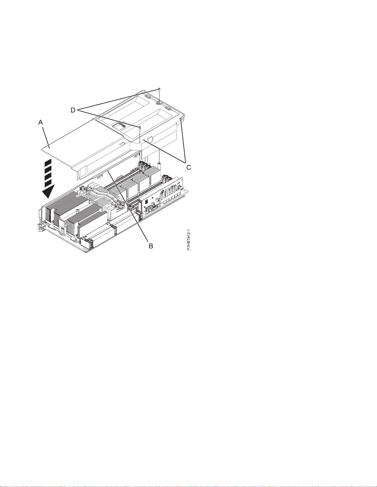
10. Perform the following steps to install the system processor assembly cover as shown in the following
figure:
a. Push the cover (A) down and slide it to the left under the flange (B).
b. Tighten the screws (C).
Figure 1. Installing the system processor assembly cover
11. Check for the protective cover that might be present on the lower-right connector pins. If a protective
cover is present, remove the cover (A), as shown in Figure 2 on page 5.
CAUTION:
Leaving the protective cover in place will prevent the installation of the processor and could
damage the connector on the system backplane.
4 System Processor Assembly
Page 17
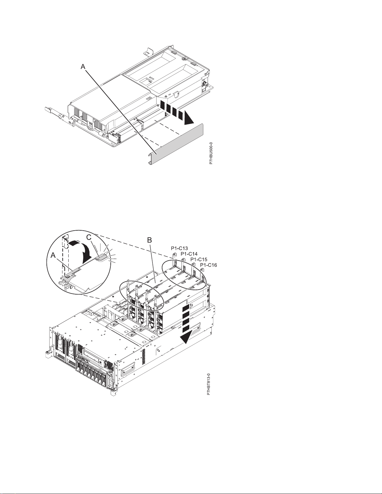
Figure 2. Removing the protective cover from the connector pins
12. With the latches (A) in the unlocked position, place the system processor assembly (B) into the
system as shown in Figure 3.
13. Move each latch (A) in the direction of the arrow to lock the system processor assembly into
position.
Figure 3. Installing the system processor in a rack-mounted system
14. Replace the service access cover. See “Installing the service access cover on an 33E/8B or 36E/8C
system” on page 27.
15. If you have a rack-mounted system, place it in the operating position. See “Placing the 33E/8B or
36E/8C in the operating position” on page 31.
16. Restore power to the system by reconnecting the system power cables.
Installing the 33E/8B or 36E/8C system processor assembly 5
Page 18

17. Start the system or logical partition. See “Starting the system or logical partition” on page 20.
18. Verify that the system processor assembly is functional. See “Verifying the installed part” on page 34.
6 System Processor Assembly
Page 19

Removing and replacing the 33E/8B or 36E/8C system processor assembly
Learn how to remove or replace the system processor assembly.
Before you begin
To complete these procedures you need the following additional documentation that can be printed for
reference:
v Memory modules
v Voltage regulators
About this task
The following procedures describe the removal and replacement of the system processor assembly.
Related information:
Voltage regulator
Memory module
Removing the 33E/8B or 36E/8C system processor assembly
Learn how to remove the system processor assembly.
About this task
If your system is managed by the Hardware Management Console (HMC), use the HMC to remove the
system processor assembly from the server. For information about using the HMC to remove the system
processor assembly, see Removing a part using the Hardware Management Console.
If your system is managed by the Systems Director Management Console (SDMC), use the SDMC to
remove the system processor assembly from the server. For instructions, see Removing a part using the
Systems Director Management Console.
If you do not have an HMC or SDMC, complete the following steps to remove either the system
processor assembly or the filler for the system processor assembly:
Procedure
1. Perform the prerequisite tasks listed in “Before you begin” on page 13.
2. If necessary, identify the system processor assembly that you need to replace. See “Identifying a
part” on page 15.
3. Stop the system or logical partition. See “Stopping a system or logical partition” on page 22.
4. Place the system in the service position. See “Placing the 33E/8B or 36E/8C in the service position”
on page 28.
5. Remove the service access cover. See “Removing the service access cover from an 33E/8B or 36E/8C
system” on page 26.
6. Attach the wrist strap.
7
Page 20
Attention:
v Attach a wrist strap to an unpainted metal surface of your hardware to prevent electrostatic
discharge (ESD) from damaging your hardware.
v When using a wrist strap, follow all electrical safety procedures. A wrist strap is for static control.
It does not increase or decrease your risk of receiving electric shock when using or working on
electrical equipment.
v If you do not have a wrist strap, just prior to removing the product from ESD packaging and
installing or replacing hardware, touch an unpainted metal surface of the system for a minimum
of 5 seconds.
7. Disconnect the power cables from the primary power supply and secondary power supply if present.
Note: This system has a second power supply. Before continuing with this procedure, ensure that
the power source to the system has been completely disconnected.
(L003)
or
8. As shown in Figure 4 on page 9, unlock the latches (A) on the system processor assembly. Using
both hands, grasp the unlocked latches (B) to pull the system processor assembly (C) through the
guide rails away from the system backplane assembly.
8 System Processor Assembly
Page 21
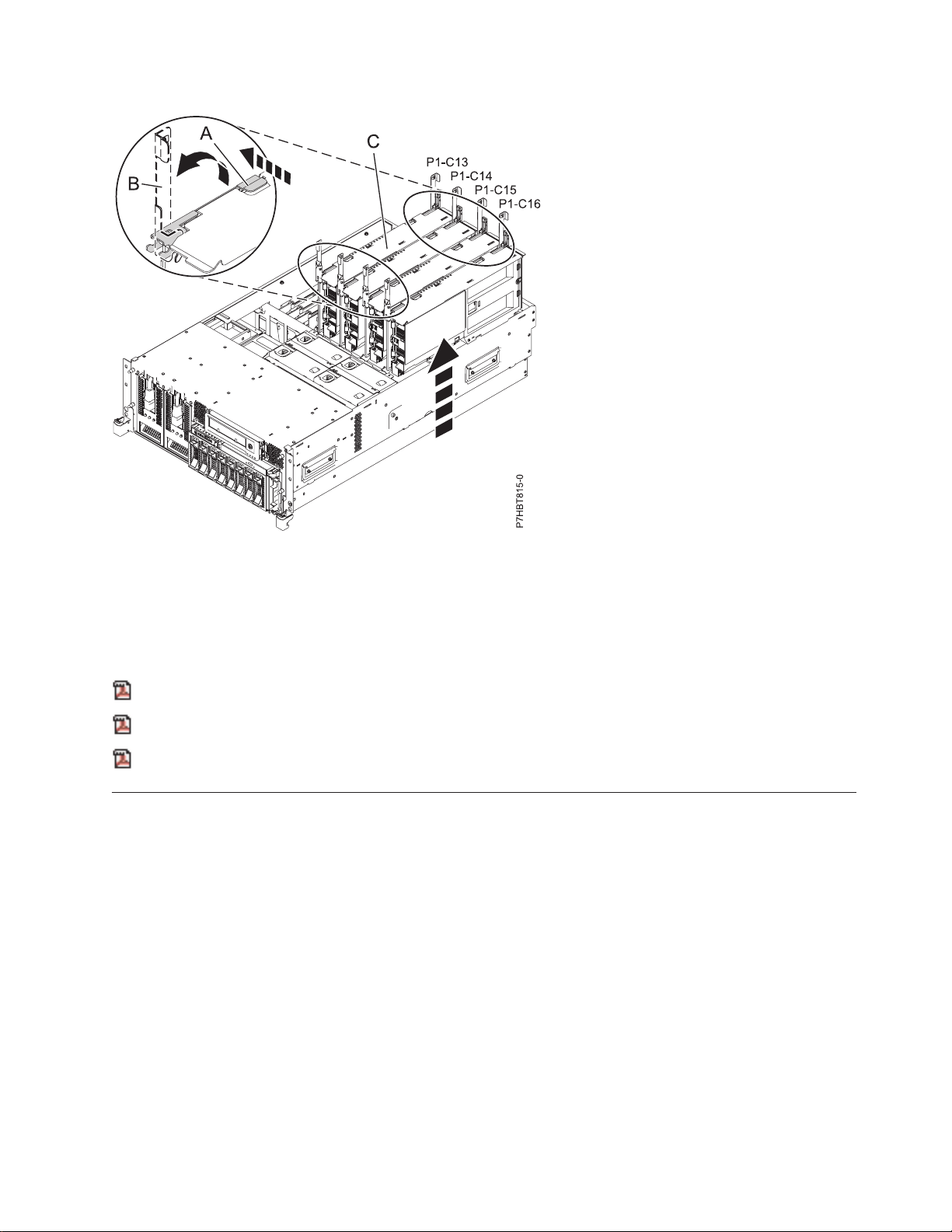
Figure 4. Removing system processor assembly from the backplane assembly in a rack-mounted system
9. Place the system processor assembly on an acceptable ESD surface.
10. If necessary, remove the memory modules to reinstall them in the new system processor assembly.
See Memory modules.
Related information:
Removing a feature using the HMC
Removing a feature using the SDMC
Memory module
Replacing the 33E/8B or 36E/8C system processor assembly
Learn how to replace the system processor assembly.
About this task
To complete this procedure, you must have already completed the removal procedure. For the removal
procedure instructions, see Removing the 33E/8B or 36E/8C system processor assembly.
If your system is managed by the Hardware Management Console (HMC), you can use the HMC to
replace the system processor assembly. For information about using the HMC to replace the system
processor assembly, see Exchanging a part using the Hardware Management Console.
If your system is managed by the Systems Director Management Console (SDMC), use the SDMC to
replace the system processor assembly. For instructions, see Replacing a part using the Systems Director
Management Console.
If you do not have an HMC or SDMC, complete the following steps to replace the system processor
assembly:
Removing and replacing the 33E/8B or 36E/8C system processor assembly 9
Page 22
Attention:
Attach a wrist strap to an unpainted metal surface of your hardware to prevent electrostatic discharge
from damaging your hardware.
When using a wrist strap, follow all electrical safety procedures. A wrist strap is for static control. It
does not increase or decrease your risk of receiving electric shock when using or working on electrical
equipment.
If you do not have a wrist strap prior to removing the product from ESD packaging and installing or
replacing hardware, touch an unpainted metal surface of the system for a minimum of 5 seconds.
Procedure
1. If necessary, remove the system processor assembly from its antistatic package.
2. Move the existing memory modules or memory fillers in to the new system processor assembly. Use
the same configuration that you had before you removed the memory modules. See the memory
module information you printed for this procedure. If you did not print the memory module topic,
see Memory modules.
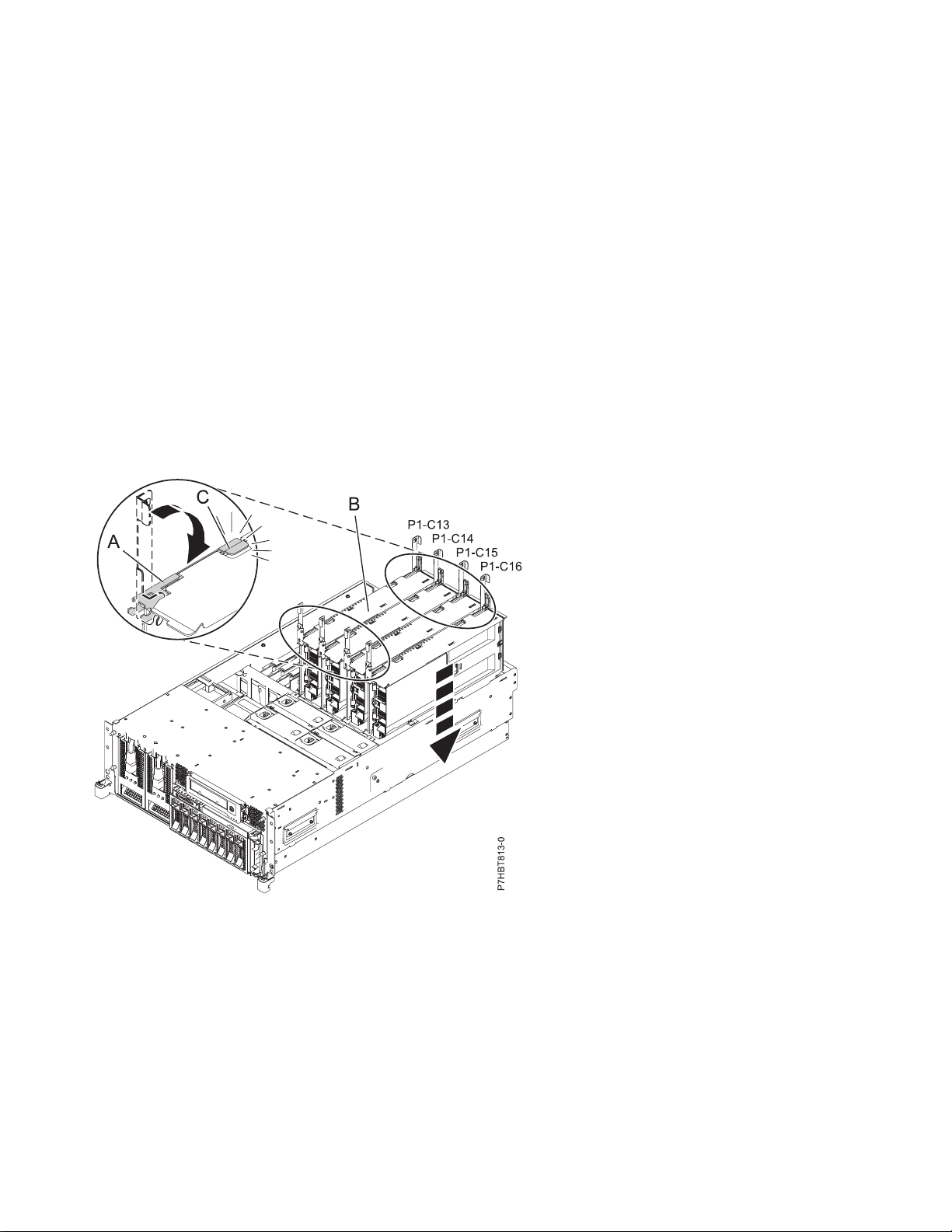
3. With the latches (A) in the unlocked position, correctly align the system processor assembly (B) and
slide it through the guide rails into the system backplane assembly.
Figure 5. Installing the system processor assembly into the backplane assembly of a rack-mounted model
4. Move the latches (A) in the direction of the arrow to lock the system processor assembly into
position.
5. Replace the service access cover. For instructions, see “Installing the service access cover on an
33E/8B or 36E/8C system” on page 27.
6. Place the system in the operating position. For instructions, see “Placing the 33E/8B or 36E/8C in
the operating position” on page 31.
7. Restore power to the system by reconnecting the system power cables.
8. Start the system or logical partition. For instructions, see “Starting the system or logical partition” on
page 20.
10 System Processor Assembly
Page 23

9. Verify that the system processor assembly is functional. For instructions, see “Verifying the installed
part” on page 34.
10. Do one of the following actions:
v If you received new activation codes for your feature, see Activate Capacity on Demand or
Advanced POWER
®
Virtualization for more information about entering the new code.
v If you did not receive a new activation code but one is required, see Order Capacity on Demand
to enter the new code order. After you receive your new activation code, see Activate Capacity on
Demand or Advanced POWER Virtualization for more information about entering the new code.
To search for an activation code for a specific system, see Capacity on Demand activation codes.
Related information:
Installing a feature using the HMC
Installing a feature using the SDMC
Replacing a feature using the HMC
Replacing a feature using the SDMC
Memory module
Voltage regulator
Removing and replacing the 33E/8B or 36E/8C system processor assembly 11
Page 24

12 System Processor Assembly
Page 25

Common procedures for installable features
This section contains the common procedures related to installing, removing, and replacing features.
Before you begin
Observe these precautions when you are installing, removing, or replacing features and parts.
About this task
These precautions are intended to create a safe environment to service your system and do not provide
steps for servicing your system. The installation, removal, and replacement procedures provide the
step-by-step processes required to service your system.
DANGER
When working on or around the system, observe the following precautions:
Electrical voltage and current from power, telephone, and communication cables are hazardous. To
avoid a shock hazard:
v Connect power to this unit only with the provided power cord. Do not use the provided power
cord for any other product.
v Do not open or service any power supply assembly.
v Do not connect or disconnect any cables or perform installation, maintenance, or reconfiguration
of this product during an electrical storm.
v The product might be equipped with multiple power cords. To remove all hazardous voltages,
disconnect all power cords.
v Connect all power cords to a properly wired and grounded electrical outlet. Ensure that the outlet
supplies proper voltage and phase rotation according to the system rating plate.
v Connect any equipment that will be attached to this product to properly wired outlets.
v When possible, use one hand only to connect or disconnect signal cables.
v Never turn on any equipment when there is evidence of fire, water, or structural damage.
v Disconnect the attached power cords, telecommunications systems, networks, and modems before
you open the device covers, unless instructed otherwise in the installation and configuration
procedures.
v Connect and disconnect cables as described in the following procedures when installing, moving,
or opening covers on this product or attached devices.
To Disconnect:
1. Turn off everything (unless instructed otherwise).
2. Remove the power cords from the outlets.
3. Remove the signal cables from the connectors.
4. Remove all cables from the devices
To Connect:
1. Turn off everything (unless instructed otherwise).
2. Attach all cables to the devices.
3. Attach the signal cables to the connectors.
4. Attach the power cords to the outlets.
5. Turn on the devices.
(D005a)
DANGER
13
Page 26
Observe the following precautions when working on or around your IT rack system:
v Heavy equipment–personal injury or equipment damage might result if mishandled.
v Always lower the leveling pads on the rack cabinet.
v Always install stabilizer brackets on the rack cabinet.
v To avoid hazardous conditions due to uneven mechanical loading, always install the heaviest
devices in the bottom of the rack cabinet. Always install servers and optional devices starting
from the bottom of the rack cabinet.
v Rack-mounted devices are not to be used as shelves or work spaces. Do not place objects on top
of rack-mounted devices.
v Each rack cabinet might have more than one power cord. Be sure to disconnect all power cords in
the rack cabinet when directed to disconnect power during servicing.
v Connect all devices installed in a rack cabinet to power devices installed in the same rack
cabinet. Do not plug a power cord from a device installed in one rack cabinet into a power
device installed in a different rack cabinet.
v An electrical outlet that is not correctly wired could place hazardous voltage on the metal parts of
the system or the devices that attach to the system. It is the responsibility of the customer to
ensure that the outlet is correctly wired and grounded to prevent an electrical shock.
CAUTION
v Do not install a unit in a rack where the internal rack ambient temperatures will exceed the
manufacturer's recommended ambient temperature for all your rack-mounted devices.
v Do not install a unit in a rack where the air flow is compromised. Ensure that air flow is not
blocked or reduced on any side, front, or back of a unit used for air flow through the unit.
v Consideration should be given to the connection of the equipment to the supply circuit so that
overloading of the circuits does not compromise the supply wiring or overcurrent protection. To
provide the correct power connection to a rack, refer to the rating labels located on the
equipment in the rack to determine the total power requirement of the supply circuit.
v (For sliding drawers.) Do not pull out or install any drawer or feature if the rack stabilizer brackets
are not attached to the rack. Do not pull out more than one drawer at a time. The rack might
become unstable if you pull out more than one drawer at a time.
v (For fixed drawers.) This drawer is a fixed drawer and must not be moved for servicing unless
specified by the manufacturer. Attempting to move the drawer partially or completely out of the
rack might cause the rack to become unstable or cause the drawer to fall out of the rack.
(R001)
Before you begin a replacement or installation procedure, perform these tasks:
Procedure
1. If you are installing a new feature, ensure that you have the software required to support the new
feature. See IBM
2. If you are performing an installation or replacement procedure that might put your data at risk,
ensure, wherever possible, that you have a current backup of your system or logical partition
(including operating systems, licensed programs, and data).
3. Review the installation or replacement procedure for the feature or part.
4. Note the significance of color on your system.
®
Prerequisite website at add URL here.
14 System Processor Assembly
Page 27

Blue or terra-cotta on a part of the hardware indicates a touch point where you can grip the hardware
to remove it from or install it in the system, open or close a latch, and so on. Terra-cotta might also
indicate that the part can be removed and replaced with the system or logical partition power on.
5. Ensure that you have access to a medium flat-blade screwdriver, a Phillips screwdriver, and a pair of
scissors.
6. If parts are incorrect, missing, or visibly damaged, do the following:
v If you are replacing a part, contact the provider of your parts or next level of support.
v If you are installing a feature, contact one of the following service organizations:
– The provider of your parts or next level of support.
7. If you encounter difficulties during the installation, contact your service provider, or your next level
of support.
8. If you are installing new hardware in a logical partition, you need to understand and plan for the
implications of partitioning your system. For information, see Logical Partitioning.
Identifying a part
Use these instructions to learn how to identify the location of a failed part, the location of a part to be
removed, or the location to install a new part on your system or expansion unit using the appropriate
method for your system.
About this task
For systems servers that contain the POWER7®processor, the light-emitting diodes (LEDs) can be used to
identify or verify the location of a part that you are removing, servicing, or installing.
The combination identify and fault LED (amber color) shows the location of a field replaceable unit
(FRU). When removing a FRU, first verify whether you are working on the correct FRU by using the
identify function in the management console or other user interface. When removing a FRU by using the
hardware management console, the identify function is activated and deactivated automatically at the
correct times.
The identify function causes the amber LED to flash. When you turn off the identify function, the LED
returns to the state it was previously. For parts that have a blue service button, the identify function sets
LED information for the service button so that when the button is pressed, the correct LEDs on that part
flash.
If you need to use the identify function, use the following procedures.
Control panel LEDs
Use this information as a guide to the control panel LEDs and buttons.
The control panel has LEDs that indicate various system status.
Common procedures for installable features 15
Page 28
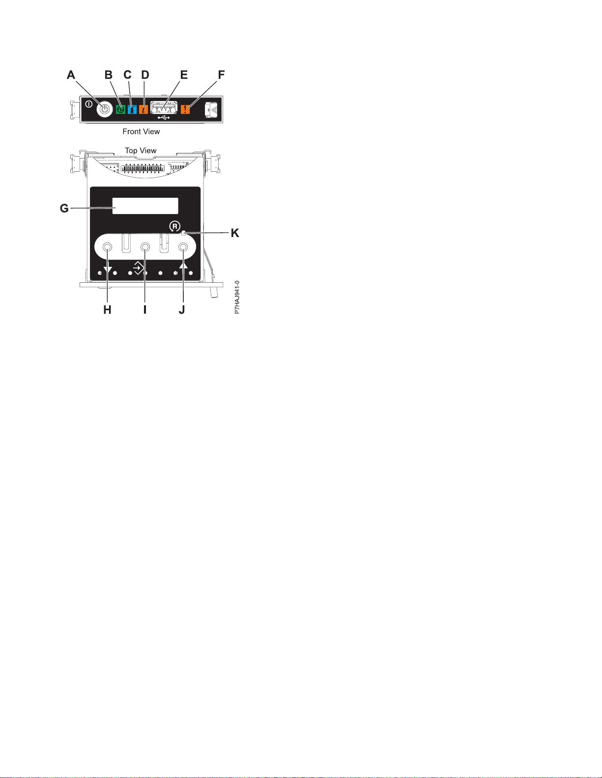
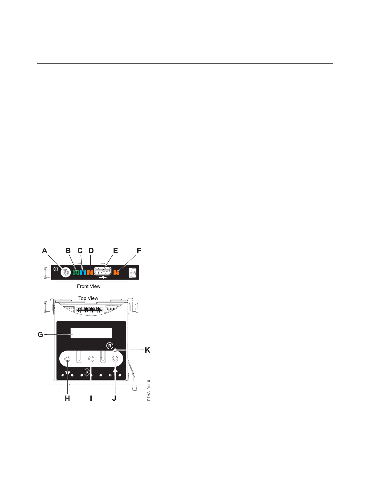
Figure 6. Control panel
v A: Power-on button
v B: Power LED
– A constant light indicates full system power to the unit.
– A flashing light indicates standby power to the unit.
Note: There is approximately a 30-second transition period from the time the power-on button is
pressed to when the power LED goes from flashing to solid. During the transition period, the LED
might flash faster.
v C: Enclosure identify light
– A constant light indicates the identify state, which is used to identify a part.
– No light indicates that the system is operating normally.
v D: System information light
– No light indicates that the system is operating normally.
– Light on indicates that the system requires attention.
v E: USB port
v F: Enclosure fault roll-up light
– A constant light indicates a fault in the system unit.
– No light indicates that the system is operating normally.
v G: Function/Data display
v H: Decrement button
v I: Enter button
v J: Increment button
v K: Pinhole reset button
16 System Processor Assembly
Page 29

Related concepts:
Identifying a failing part
Use these instructions to learn how to locate and identify a failing part on your system or expansion unit
using the appropriate method for your system.
Identifying a failing part in an AIX system or logical partition
Use these instructions to learn how to locate a failing part, and then activate the indicator light for that
part on a system or logical partition running the AIX®operating system.
Locating a failing part in an AIX system or logical partition
You might need to use AIX tools, before activating the indicator light, to locate a part that is failing.
Procedure
1. Log in as root user or celogin-.
2. At the command line, type diag and press Enter.
3. From the Function Selection menu, select Task Selection and press Enter.
4. Select Display Previous Diagnostic Results and press Enter.
5. From the Display Previous Diagnostic Results display, select Display Diagnostic Log Summary. The
Display Diagnostic Log display shows a chronological list of events.
6. Look in the T column for the most recent S entry. Select this row in the table and press Enter.
7. Select Commit. The details of this log entry are shown.
8. Record the location information and the SRN value shown near the end of the entry.
9. Exit to the command line.
What to do next
Use the location information for the failing part to activate the indicator light that identifies the failing
part. See “Activating the indicator light for the failing part.”
Activating the indicator light for the failing part
Use these instructions to help physically identify the location of a part you are servicing.
About this task
To activate the indicator light for a failing part, complete the following steps:
Procedure
1. Log in as root user.
2. At the command line, type diag and press Enter.
3. From the Function Selection menu, select Task Selection and press Enter.
4. From the Task Selection menu, select Identify and Attention Indicators and press Enter.
5. From the list of lights, select the location code for the failing part and press Enter.
6. Select Commit. This turns on the system attention and indicator light for the failing part.
7. Exit to the command line.
Deactivating the failing-part indicator light
Use this procedure to turn off any indicator light that you turned on as a part of a service action.
About this task
To deactivate the indicator light, complete the following steps:
Common procedures for installable features 17
Page 30

Procedure
1. Log in as root user.
2. At the command line, type diag and press Enter.
3. From the Function Selection menu, select Task Selection and press Enter.
4. From the Task Selection menu, select Identify and Attention Indicators and press Enter.
5. From the list of lights, select the location code for the failing part and press Enter. When a light is
activated for a failing part, an I character precedes the location code.
6. Select Commit. This turns off the system attention and indicator light for the failing part.
7. Exit to the command line.
Identifying a failing part in a Linux system or logical partition
If the service aids have been installed on a system or logical partition, you can activate or deactivate the
indicator lights to locate a part or complete a service action.
Locating a failing part in a Linux system or logical partition
If the service aids have been installed on a system or logical partition, you need to activate the indicator
lights to locate a part.
About this task
To activate the indicator light, follow these steps:
Procedure
1. Log in as root user.
2. At the command line, type /usr/sbin/usysident -s identify -l location_code and press Enter.
3. Look for the system attention light to identify the enclosure that contains the failing part.
Finding the location code of a failing part in a Linux system or logical partition
To retrieve the location code of the failing part, if you do not know the location code, use the procedure
in this topic.
About this task
To locate the failing part in a system or logical partition, follow these steps:
Procedure
1. Log in as root user.
2. At the command line, type grep diagela /var/log/platform and press Enter.
3. Look for the most recent entry that contains a system reference code (SRC).
4. Record the location information.
Activating the indicator light for the failing part
If you know the location code of the failing part, activate the indicator light to help you locate which part
to replace.
About this task
To activate the indicator light, follow these steps:
Procedure
1. Log in as root user.
2. At the command line, type /usr/sbin/usysident -s identify -l location_code and press Enter.
18 System Processor Assembly
Page 31

3. Look for the system attention light to identify the enclosure that contains the failing part.
Deactivating the failing-part indicator light
After you complete a removal and replacement procedure, you must deactivate the failing-part indicator
light.
About this task
To deactivate the indicator light, follow these steps:
Procedure
1. Log in as root user.
2. At the command line, type /usr/sbin/usysident -s normal -l location_code and press Enter.
Locating a failing part in a Virtual I/O Server system or logical partition
You can use Virtual I/O Server (VIOS) tools, before activating the indicator light, to locate a part that is
failing.
About this task
To locate the failing part, follow these steps:
Procedure
1. Log in as root user or celogin-.
2. At the command line, type diagmenu and press Enter.
3. From the Function Selection menu, select Task Selection and press Enter.
4. Select Display Previous Diagnostic Results and press Enter.
5. From the Display Previous Diagnostic Results display, select Display Diagnostic Log Summary.A
Display Diagnostic Log display appears. This display contains a chronological list of events.
6. Look in the T column for the most recent S entry. Select this row in the table and press Enter.
7. Choose Commit. The details of this log entry are shown.
8. Record the location information and the SRN value shown near the end of the entry.
9. Exit to the command line.
Results
Use the location information for the failing part to activate the indicator light that identifies the failing
part. For instructions, see “Identifying a part by using the Virtual I/O Server.”
Identifying a part by using the Virtual I/O Server
You can use Virtual I/O Server (VIOS) tools to physically locate a part.
About this task
To turn on the indicator light for identifying a part, follow these steps:
Procedure
1. Log in as root user.
2. At the command line, type diagmenu and press Enter.
3. From the Function Selection menu, select Task Selection and press Enter.
4. From the Task Selection menu, select Identify and Attention Indicators and press Enter.
5. From the list of lights, select the location code for the failing part and press Enter.
Common procedures for installable features 19
Page 32
6. Select Commit. This turns on the system attention and indicator light for the failing part.
7. Exit to the command line.
Starting the system or logical partition
Learn how to start a system or logical partition after performing a service action or system upgrade.
Starting a system that is not managed by a HMC or an SDMC
You can use the power button or the Advanced System Management Interface (ASMI) to start a system
that is not managed by a Hardware Management Console (HMC) or an Systems Director Management
Console (SDMC).
About this task
To start a system that is not managed by a HMC or SDMC, follow these steps:
Procedure
1. Open the front rack door, if necessary.
2. Before you press the power button on the control panel, ensure that power is connected to the system
unit as follows:
v All system power cables are connected to a power source.
v The power LED, as shown in the following figure, is slowly flashing.
v The top of the display, as shown in the following figure, shows 01 V=F.
3. Press the power button (A), as shown in the following figure, on the control panel.
Figure 7. Control panel
v A: Power-on button
v B: Power LED
– A constant light indicates full system power to the unit.
– A flashing light indicates standby power to the unit.
20 System Processor Assembly
Page 33

Note: There is approximately a 30-second transition period from the time the power-on button is
pressed to when the power LED goes from flashing to solid. During the transition period, the LED
might flash faster.
v C: Enclosure identify light
– A constant light indicates the identify state for the enclosure or for a resource within the
enclosure.
– No light indicates that no resources in the enclosure are being identified.
v D: Attention light
– No light indicates that the system is operating normally.
– A solid light indicates that the system requires attention.
v E: USB port
v F: Enclosure fault roll-up light
– A constant light indicates a fault indicator active in the system.
– No light indicates that the system is operating normally.
v G: Function/Data display
v H: Decrement button
v I: Enter button
v J: Increment button
v K: Pinhole reset button
4. Observe the following aspects after pressing the power button:
v The power-on light begins to flash faster.
v The system cooling fans are activated after approximately 30 seconds and begin to accelerate to
operating speed.
v Progress indicators, also referred to as checkpoints, appear on the control panel display while the
system is being started. The power-on light on the control panel stops flashing and remains on,
indicating that the system power is on.
What to do next
Tip: If pressing the power button does not start the system, do the following steps to start the system by
using the Advanced System Management Interface (ASMI):
1. Access the ASMI. For instructions, see Accessing the ASMI without an HMC.
2. Start the system by using the ASMI. For instructions, see Powering the system on and off.
Starting a system or logical partition by using the HMC
You can use the Hardware Management Console (HMC) to start the system or logical partition after the
required cables are installed and the power cables are connected to a power source.
About this task
For instructions on working with the HMC, see Managing the Hardware Management Console. For
instructions on starting a logical partition, see Logical partitioning. For instructions on starting the
system, see Powering on the managed system.
Progress indicators, also referred to as checkpoints, appear on the control panel display while the system
is being started. When the power-on light on the control panel stops blinking and remains on, the system
power is on.
Common procedures for installable features 21
Page 34

Starting a system or virtual server by using the SDMC
You can use the Systems Director Management Console (SDMC) to start the system or virtual server after
the required cables are installed and the power cables are connected to a power source.
About this task
For instructions on working with the SDMC, see Managing and configuring the SDMC. For instructions
on starting a virtual server, see Managing virtual servers. For instructions on shutting down and
restarting virtual servers, see Shutting down and restarting virtual servers.
Progress indicators, also known as checkpoints, display on the control panel while the system is being
started. When the power-on light on the control panel stops flashing and remains on, the system power is
on.
Stopping a system or logical partition
Learn how to stop a system or logical partition as a part of a system upgrade or service action.
About this task
Attention: Using either the power-on button on the control panel or entering commands at the
Hardware Management Console (HMC) to stop the system can cause unpredictable results in the data
files. Also, the next time you start the system, it might take longer if all applications are not ended before
stopping the system.
To stop the system or logical partition, select the appropriate procedure.
Stopping a system that is not managed by an HMC or an SDMC
You might need to stop the system to perform another task. If your system is not managed by the
Hardware Management Console (HMC) or the Systems Director Management Console (SDMC), use these
instructions to stop the system by using the power button or the Advanced System Management Interface
(ASMI).
Before you begin
Before you stop the system, follow these steps:
1. Ensure that all jobs are completed and end all applications.
2. Ensure that the operating system is stopped.
Attention: Failure to do so can result in the loss of data.
3. If a Virtual I/O Server (VIOS) logical partition is running, ensure that all clients are shut down or that
the clients have access to their devices by using an alternate method.
About this task
The following procedure describes how to stop a system that is not managed by the HMC or the SDMC.
Procedure
1. Log in to the system as a user with the authority to run the shutdown or pwrdwnsys (Power Down
System) command.
2. At the command line, enter one of the following commands:
v If your system is running the AIX operating system, type shutdown.
v If your system is running the Linux operating system, type shutdown -h now.
22 System Processor Assembly
Page 35
v If your system is running the operating system, type PWRDWNSYS. If your system is partitioned, use
the PWRDWNSYS command to power down each of the secondary partitions. Then, use the
PWRDWNSYS command to power down the primary partition.
The command stops the operating system. The system power turns off, the power-on light begins to
slowly flash, and the system goes into a standby state.
3. At the Linux command line, type shutdown -h now.
The command stops the operating system. The system power turns off, the power-on light begins to
slowly flash, and the system goes into a standby state.
4. Record the IPL type and the IPL mode from the control panel display to help you return the system
to this state when the installation or replacement procedure is completed.
5. Set the power switches of any devices connected to the system to off.
6. Unplug any power cables that are attached to the unit from electrical outlets. Ensure that you unplug
power cables from peripheral devices, such as printers and expansion units.
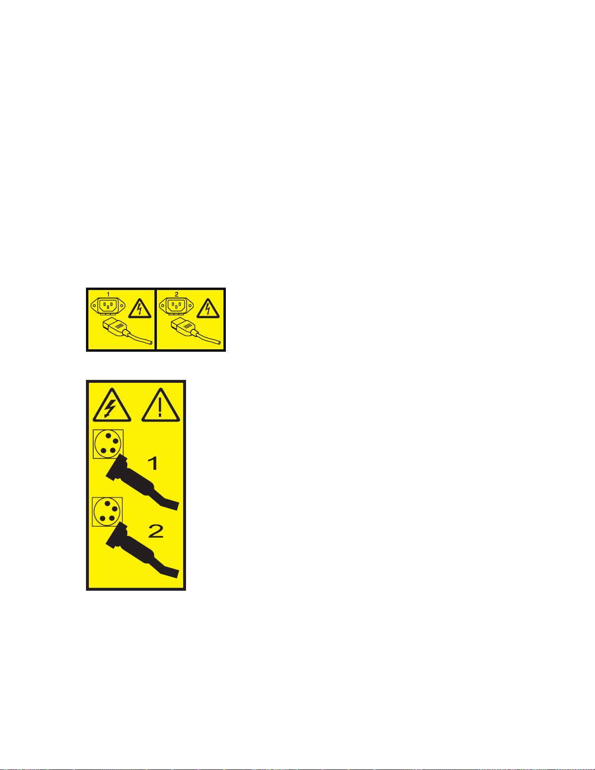
Important: The system may be equipped with a second power supply. Before continuing with this
procedure, ensure that all power sources to the system have been disconnected.
(L003)
or
Stopping a system by using the HMC
You can use the Hardware Management Console (HMC) to stop the system or a logical partition.
Common procedures for installable features 23
Page 36

About this task
By default, the managed system is set to power off automatically when you shut down the last running
logical partition on the managed system. If you set the managed system properties on the HMC so that
the managed system does not power off automatically, you must use this procedure to power off your
managed system.
Attention: If possible, shut down the running logical partitions on the managed system before powering
off the managed system. Powering off the managed system without shutting down the logical partitions
first causes the logical partitions to shut down abnormally and can cause data loss. If you use a Virtual
I/O Server (VIOS) logical partition, ensure that all clients are shut down or that the clients have access to
their devices using an alternate method.
To power off a managed system, you must be a member of one of the following roles:
v Super administrator
v Service representative
v Operator
v Product engineer
Use the following steps to stop the system by using the HMC:
Procedure
1. In the navigation area, expand the Systems Management folder.
2. Click the Servers icon.
3. In the Contents area, select the managed system.
4. Select Tasks > Operations > Power Off.
5. Select the appropriate power-off mode and click OK.
Related information:
Shutting down and restarting logical partitions
Stopping a system by using the SDMC
You can use the Systems Director Management Console (SDMC) user interface to stop the system or a
virtual server.
About this task
By default, the managed system is set to power off automatically when you shut down the last running
virtual server on the managed system. If you set the managed system properties on the SDMC so that the
managed system does not power off automatically, you must use this procedure to power off your
managed system.
Attention: If possible, shut down the running virtual servers on the managed system before powering
off the managed system. Powering off the managed system without shutting down the virtual servers
first causes the virtual servers to shut down abnormally and can cause data loss. If you use a Virtual I/O
Server (VIOS) logical partition, ensure that all clients are shut down or that the clients have access to
their devices with an alternate method.
To power off a managed system, you must be a member of one of the following roles:
v Super administrator
v Service representative
v Operator
v Product engineer
24 System Processor Assembly
Page 37
Use the following steps to stop the system by using the SDMC.
Procedure
1. In the Power Systems™Resource area, select the managed system you want to power off.
2. From the Actions menu, select Operations > Power Off.
3. Select the appropriate power-off mode and click OK.
Removing and replacing covers for the 33E/8B or 36E/8C system
Use these instructions to remove, replace, or install covers to access components or perform service.
Removing the front cover from an 33E/8B or 36E/8C system
Use this procedure to remove the cover to access components or perform service.
About this task
To remove the front cover, follow these steps:
Procedure
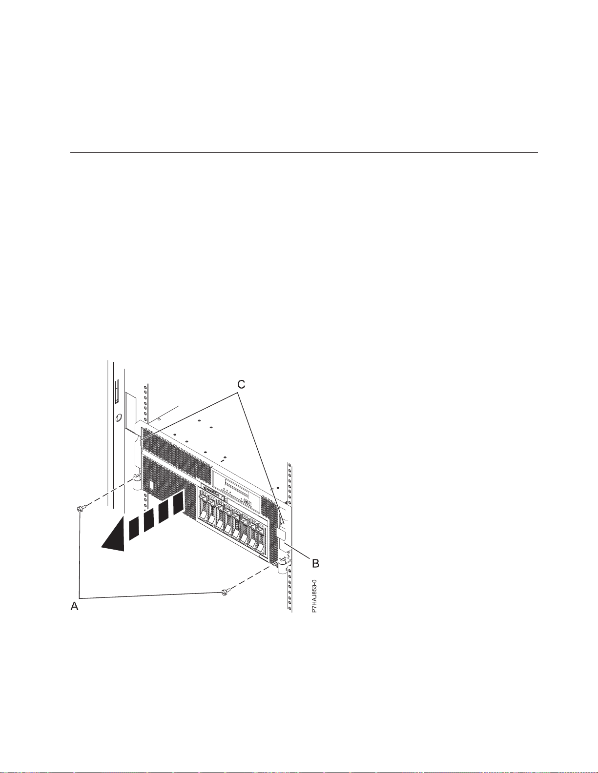
1. Remove the two screws (A) that secure the system to the rack (B) as shown in the following figure.
2. Pull the cover away from the system. The cover has an indentation where you can hold onto it more
easily.
Figure 8. Removing the front cover
Installing the front cover on an 33E/8B or 36E/8C system
Use this procedure to install the cover after accessing components or performing service.
About this task
To install the front cover, follow these steps:
Common procedures for installable features 25
Page 38
Procedure
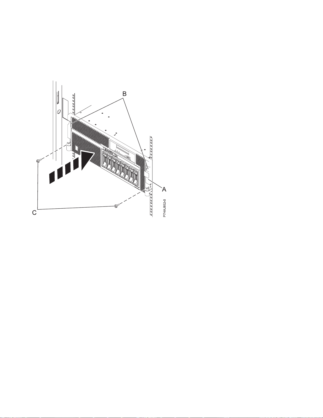
1. Align the cover with the system.
2. Gently push the cover in until the four cover clips are seated in their respective mounting posts (B)
on the system.
3. Replace the two screws (C) that secure the system to the rack (A).
Figure 9. Installing the front cover
Removing the service access cover from an 33E/8B or 36E/8C system
Use this procedure to remove the service access cover to perform service or to gain access to internal
components.
About this task
To remove the service access cover, follow these steps:
Procedure
1. Place the system into the service position. For instructions, see “Placing the 33E/8B or 36E/8C in the
service position” on page 28.
2. Loosen the two thumbscrews (A) located at the rear of the cover.
3. Slide the cover (B) toward the rear of the system unit. When the front of the service access cover
clears the upper frame ledge, lift the cover up and off the system unit.
Results
Attention: For proper cooling and airflow, install the cover before starting the system. Operating the
system without the cover for more than 30 minutes could damage the system components.
26 System Processor Assembly
Page 39
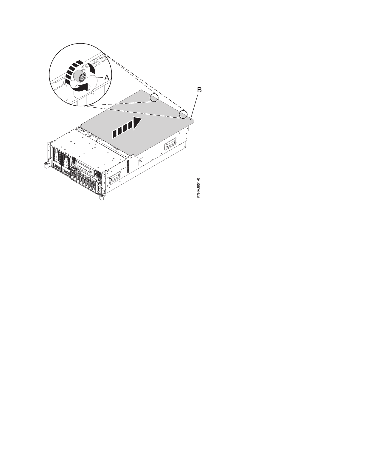
Figure 10. Removing the service access cover
Installing the service access cover on an 33E/8B or 36E/8C system
Use this procedure to install the service access cover after performing service or accessing internal
components.
About this task
To install the service access cover, follow these steps:
Procedure
1. Place the service access cover (A) on the top of the system unit, approximately 25 mm (1 in.) from the
front of the system unit.
2. Hold the service access cover against the system unit, and slide it toward the front of the system.
The tabs on the service access cover slide beneath the upper chassis ledge, and the two screws align
with the screw holes at the rear of the system unit.
Important: Ensure that the fan LED cables do not get caught on the front edge of the service access
cover as you move it forward.
3. Tighten the screws (B) located at the rear of the cover.
Common procedures for installable features 27
Page 40
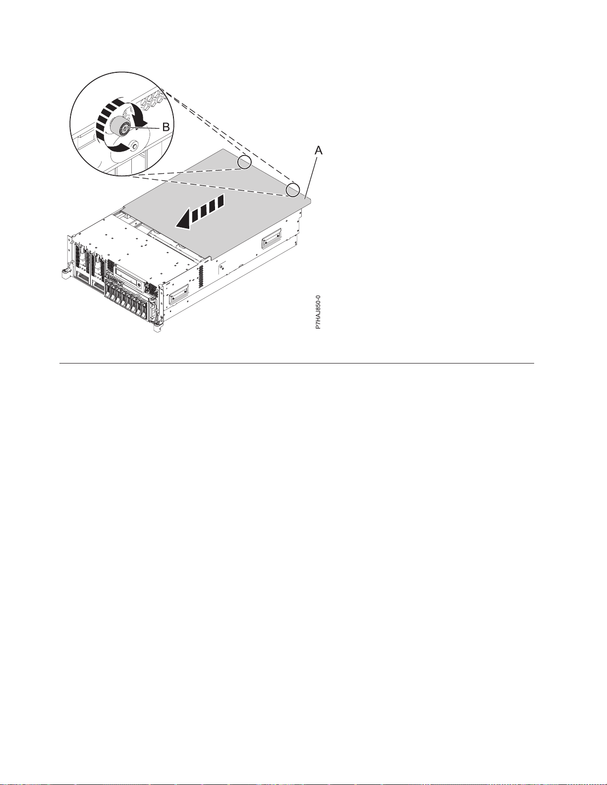
Figure 11. Installing the service access cover
Placing the rack-mounted 33E/8B or 36E/8C system into the service position or operating position
Use these procedures to place a system into the service position or operating position to perform service
or to gain access to internal components.
Placing the 33E/8B or 36E/8C in the service position
Use this procedure to perform service or gain access to internal components by placing the rack-mounted
system or expansion unit in the service position.
About this task
Note: Some of the figures in these procedures might not look exactly like the system or expansion unit
that you have. However, the steps to perform the task are the same.
28 System Processor Assembly
Page 41

DANGER
When working on or around the system, observe the following precautions:
Electrical voltage and current from power, telephone, and communication cables are hazardous. To
avoid a shock hazard:
v Connect power to this unit only with the provided power cord. Do not use the provided power
cord for any other product.
v Do not open or service any power supply assembly.
v Do not connect or disconnect any cables or perform installation, maintenance, or reconfiguration
of this product during an electrical storm.
v The product might be equipped with multiple power cords. To remove all hazardous voltages,
disconnect all power cords.
v Connect all power cords to a properly wired and grounded electrical outlet. Ensure that the outlet
supplies proper voltage and phase rotation according to the system rating plate.
v Connect any equipment that will be attached to this product to properly wired outlets.
v When possible, use one hand only to connect or disconnect signal cables.
v Never turn on any equipment when there is evidence of fire, water, or structural damage.
v Disconnect the attached power cords, telecommunications systems, networks, and modems before
you open the device covers, unless instructed otherwise in the installation and configuration
procedures.
v Connect and disconnect cables as described in the following procedures when installing, moving,
or opening covers on this product or attached devices.
To Disconnect:
1. Turn off everything (unless instructed otherwise).
2. Remove the power cords from the outlets.
3. Remove the signal cables from the connectors.
4. Remove all cables from the devices
To Connect:
1. Turn off everything (unless instructed otherwise).
2. Attach all cables to the devices.
3. Attach the signal cables to the connectors.
4. Attach the power cords to the outlets.
5. Turn on the devices.
(D005a)
DANGER
Common procedures for installable features 29
Page 42
Observe the following precautions when working on or around your IT rack system:
v Heavy equipment–personal injury or equipment damage might result if mishandled.
v Always lower the leveling pads on the rack cabinet.
v Always install stabilizer brackets on the rack cabinet.
v To avoid hazardous conditions due to uneven mechanical loading, always install the heaviest
devices in the bottom of the rack cabinet. Always install servers and optional devices starting
from the bottom of the rack cabinet.
v Rack-mounted devices are not to be used as shelves or work spaces. Do not place objects on top
of rack-mounted devices.
v Each rack cabinet might have more than one power cord. Be sure to disconnect all power cords in
the rack cabinet when directed to disconnect power during servicing.
v Connect all devices installed in a rack cabinet to power devices installed in the same rack
cabinet. Do not plug a power cord from a device installed in one rack cabinet into a power
device installed in a different rack cabinet.
v An electrical outlet that is not correctly wired could place hazardous voltage on the metal parts of
the system or the devices that attach to the system. It is the responsibility of the customer to
ensure that the outlet is correctly wired and grounded to prevent an electrical shock.
CAUTION
v Do not install a unit in a rack where the internal rack ambient temperatures will exceed the
manufacturer's recommended ambient temperature for all your rack-mounted devices.
v Do not install a unit in a rack where the air flow is compromised. Ensure that air flow is not
blocked or reduced on any side, front, or back of a unit used for air flow through the unit.
v Consideration should be given to the connection of the equipment to the supply circuit so that
overloading of the circuits does not compromise the supply wiring or overcurrent protection. To
provide the correct power connection to a rack, refer to the rating labels located on the
equipment in the rack to determine the total power requirement of the supply circuit.
v (For sliding drawers.) Do not pull out or install any drawer or feature if the rack stabilizer brackets
are not attached to the rack. Do not pull out more than one drawer at a time. The rack might
become unstable if you pull out more than one drawer at a time.
v (For fixed drawers.) This drawer is a fixed drawer and must not be moved for servicing unless
specified by the manufacturer. Attempting to move the drawer partially or completely out of the
rack might cause the rack to become unstable or cause the drawer to fall out of the rack.
(R001)
To place the rack-mounted system or expansion unit into the service position, follow these steps:
Procedure
1. If necessary, open the front rack door.
2. Remove the two screws (A) that secure the system unit to the rack as shown in the following figure.
3. Release the rack latches (B) on both the left and right sides as shown in the following figure.
30 System Processor Assembly
Page 43
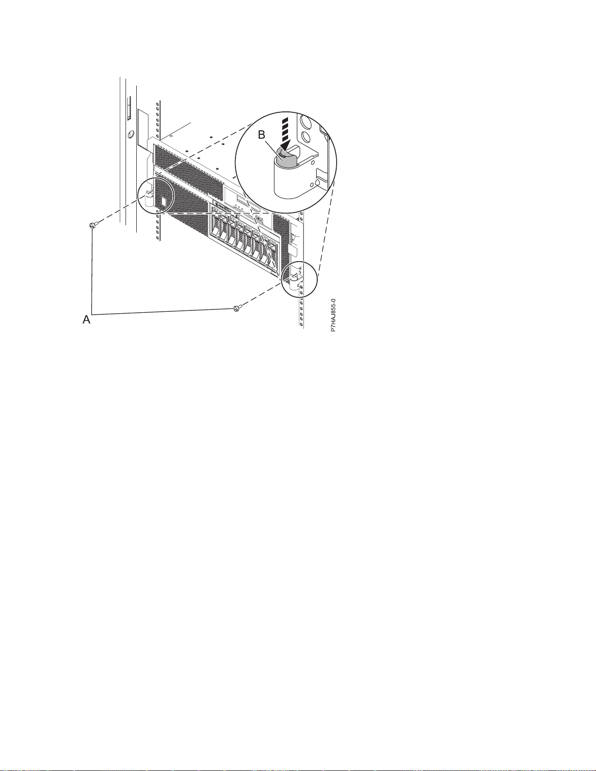
Figure 12. Releasing the rack latches
4. If required, unplug the cables from the rear of the system or expansion unit before you pull the unit
out from the rack. Ensure that the cables at the rear of the system or expansion unit do not catch or
bind as you pull the unit out from the rack.
5. Slowly pull the system or expansion unit out from the rack until the rails are fully extended and
locked. Ensure that the rails are fully extended. When the rails are fully extended, the rail safety
latches lock into place. This action prevents the system or expansion unit from being pulled out too
far.
Placing the 33E/8B or 36E/8C in the operating position
Use this procedure to place the system or expansion unit in the operating position to make the unit
available for use.
About this task
To place the system into the operating position follow these steps:
Tip: Some of the figures in these procedures might not look exactly like the system or expansion unit
that you have. However, the steps to perform the task are the same.
Procedure
1. Simultaneously release the blue rail safety latches (B), located near the front of each rail, and push the
system or expansion unit into the rack as shown in the following figure.
Note: Ensure that the cables at the rear of the system or expansion unit do not catch or bind as you
push the unit back into the rack.
Common procedures for installable features 31
Page 44
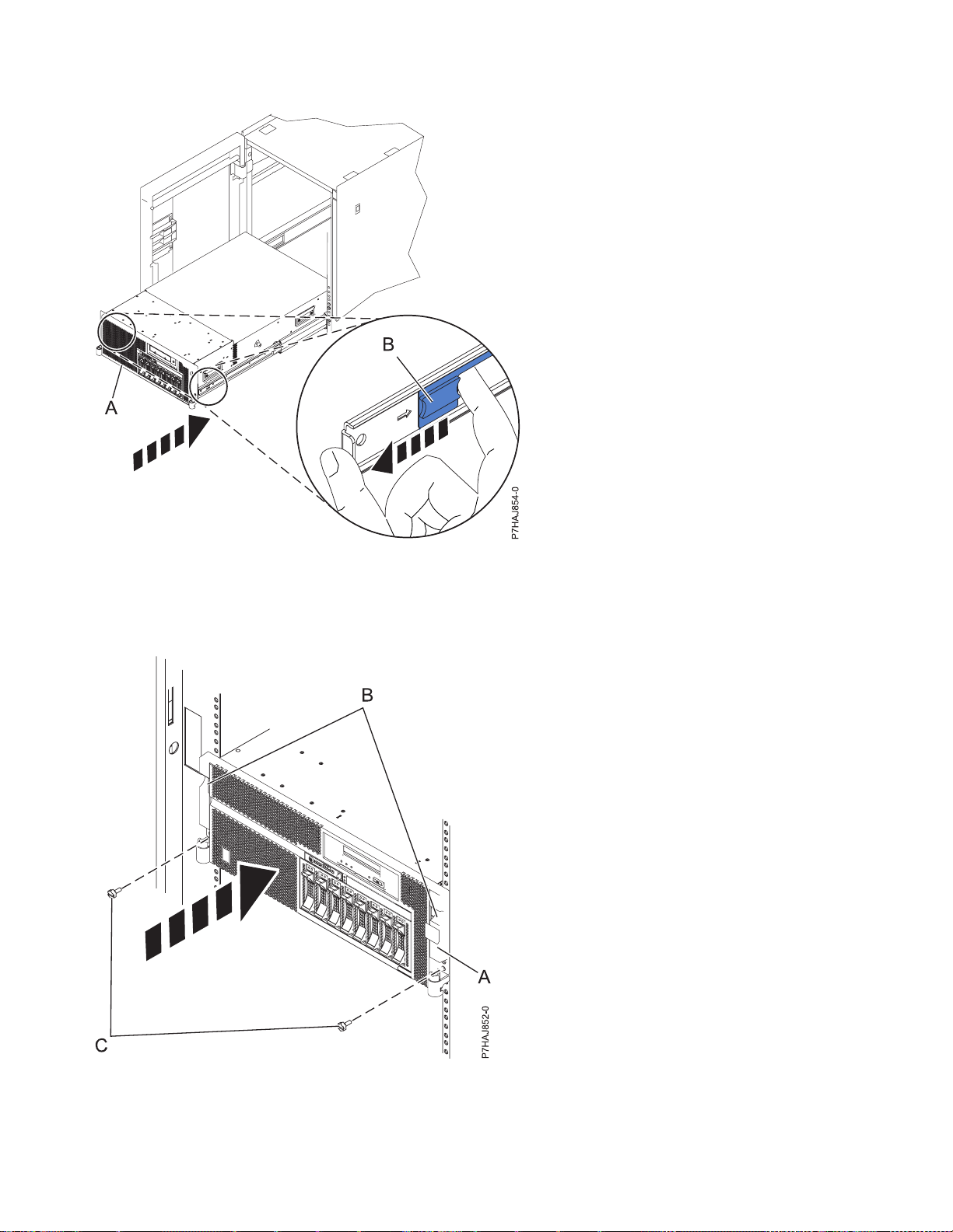
Figure 13. Releasing the rail safety latches
2. Replace and tighten the two thumbscrews (C) that secure the system or expansion unit (A) to the rack
as shown in the following figure.
Figure 14. Replacing the thumbscrews
3. Close the front rack door.
32 System Processor Assembly
Page 45

Installing a part by using the HMC
You can use the Hardware Management Console (HMC) to perform many service actions, including the
installation of a new feature or part.
Before you begin
To install a feature or part into a system or expansion unit that is managed by HMC Version 7, or later,
complete the following steps:
Procedure
1. In the navigation area, expand Systems Management > Servers.
2. Select the managed system on which you will install the part.
Note: If your part is in a miscellaneous equipment specification (MES), continue with step 3. If your
part is contained in the install done by the software sales representative (SSR) or in a ship group, go
to step 8.
3. In the Tasks area, expand Serviceability > Hardware > MES Tasks > Open MES.
4. Click Add MES Order Number.
5. Enter the number, and click OK.
6. Click the newly created order number, and click Next. The details of the order number are
displayed.
7. Click Cancel to close the window.
8. In the Tasks area, expand Serviceability > Hardware > MES Tasks.
9. Select Add FRU (field replaceable unit).
10. In the Add/Install/Remove Hardware-Add FRU, Select FRU Type window, select the system or
enclosure into which you are installing the feature.
11. Select the type of feature you are installing, and click Next.
12. Select the location code where you will install the feature, and click Add.
13. After the part is listed in the Pending Actions section, click Launch Procedure and follow the
instructions to install the feature.
Note: The HMC might open external instructions for installing the feature. If so, follow those
instructions to install the feature.
Installing a part by using the SDMC
You can use the Systems Director Management Console (SDMC) to perform many service actions,
including the installation of a new field-replaceable unit (FRU) or part.
Before you begin
To install a part into a system or expansion unit that is managed by an SDMC, complete the following
steps:
Procedure
1. In the Power Systems Resources area, select the system on which you want to install a part.
2. From the Actions menu, expand Service and Support > Hardware > MES Tasks > Add FRU.
3. On the Add FRU page, select the system or enclosure type from the Enclosure type list.
4. Select the FRU type that you are installing, and click Next.
5. Select the location code for the location to install, and click Add.
Common procedures for installable features 33
Page 46

6. After the part is placed in the Pending Actions section, click Launch Procedure and follow the
instructions to install the part.
Note: The SDMC might open external instructions for installing the feature. If so, follow those
instructions to install the part.
Verifying the installed part
You can verify a newly installed or replaced part on your system, logical partition, or expansion unit by
using the operating system, stand-alone diagnostics, or the Hardware Management Console (HMC).
Verifying an installed feature or replaced part in an AIX system or logical partition
If you installed feature or replaced a part, you might want to use the tools in the AIX operating system to
verify that the feature or part is recognized by the system or logical partition.
About this task
To verify the operation of a newly installed feature or replacement part, select the appropriate procedure:
v Verify the installed feature using AIX
v Verifying the replaced part using AIX
Verify the installed feature by using the AIX operating system:
1. Log in as root user.
2. At the command line, type diag and press Enter.
3. Select Advanced Diagnostics Routines and press Enter.
4. From the Diagnostic Mode Selection menu, select System Verification and press Enter.
5. When the Advanced Diagnostic Selection menu appears, do one of the following:
v To test a single resource, select the resource that you just installed from the list of resources and
press Enter.
v To test all the resources available to the operating system, select All Resources and press Enter.
6. Select Commit, and wait until the diagnostic programs run to completion, responding to any prompts
that appear.
7. Did the diagnostics run to completion and display the message No trouble was found?
v No: If a service request number (SRN) or other reference code is displayed, suspect a loose adapter
or cable connection. Review the installation procedures to ensure that the new feature is installed
correctly. If you cannot correct the problem, collect all SRNs or any other reference code
information that you see. If the system is running in logical partitioning (LPAR) mode, note the
logical partition in which you installed the feature. Contact your service provider for assistance.
v Yes: The new device is installed correctly. Exit the diagnostic programs and return the system to
normal operations.
Verify the replacement part by using the AIX operating system:
To verify the operation of a newly installed feature or replacement part, follow these steps:
1. Did you use either the AIX operating system or the online diagnostics service aid concurrent
(hot-swap) service to replace the part?
No: Go to step 2.
Yes: Go to step 5 on page 35.
2. Is the system powered off?
No: Go to step 4 on page 35.
34 System Processor Assembly
Page 47

Yes: Continue with the next step.
3. Start the system and wait until the AIX operating system login prompt is displayed or until apparent
system activity on the operator panel or display has stopped.
Did the AIX login prompt display?
v No: If a service request number (SRN) or other reference code is displayed, suspect a loose
adapter or cable connection. Review the procedures for the part that you replaced to ensure that
the new part is installed correctly. If you cannot correct the problem, collect all SRNs or any other
reference code information that you see. If the system does not start or you have no login prompt,
see: Problems with loading and starting the operating system.
If the system is partitioned, note the logical partition in which you replaced the part. Contact your
service provider for assistance.
v Yes: Go to step 4.
4. At the command prompt, type diag —a and press Enter to check for missing resources. If you see a
command prompt, go to step 5.
If the Diagnostic selection menu is shown with M appearing next to any resource, follow these
steps:
a. Select the resource and press Enter.
b. Select Commit.
c. Follow any instructions that are shown.
d. If the Do you want to review the previously displayed error? message is shown, select Ye s and press
Enter.
e. If an SRN is shown, suspect a loose card or connection. If no obvious problem is shown, record
the SRN and contact your service provider for assistance.
f. If no SRN is shown, go to step 5.
5. Test the part by doing the following steps:
a. At the command line, type diag and press Enter.
b. From the Function Selection menu, select Advanced Diagnostics Routines and press Enter.
c. From the Diagnostic Mode Selection menu, select System Verification and press Enter.
d. Select All Resources, or select the diagnostics for the individual part to test only the part you
replaced and any devices that are attached to the part you replaced and press Enter.
Did the Resource Repair Action menu appear?
No: Go to step 6.
Yes: Go to step 7.
6. Did the Testing Complete, No trouble was found message appear?
v No: There is still a problem. Contact your service provider. This ends the procedure.
v Yes: Select Log Repair Action, if not previously logged, from the Task Selection menu to update
the AIX error log. If the repair action was reseating a cable or adapter, select the resource
associated with that repair action. If the resource associated with your action is not displayed on
the resource list, select sysplanar0 and press Enter.
Tip: This action changes the indicator light for the part from the fault state to the normal state.
Go to step 9 on page 36.
7. Select the resource for the replaced part from the Resource Repair Action menu. When a test is run
on a resource in system verification mode, and that resource has an entry in the AIX error log, if the
test on the resource was successful, the Resource Repair Action menu appears. Complete the
following steps to update the AIX error log to indicate that a system-detectable part has been
replaced.
Common procedures for installable features 35
Page 48

Note: On systems with an indicator light for the failing part, this action changes the indicator light
to the normal state.
a. Select the resource that has been replaced from the Resource Repair Action menu. If the repair
action was reseating a cable or adapter, select the resource associated with that repair action. If
the resource associated with your action does not appear on the resource list, select sysplanar0
and press Enter.
b. Select Commit after you make your selections. Did another Resource Repair Action display
appear?
No: If the No Trouble Found display appears, go to step 9
Yes: Go to step 8.
8. Select the parent or child of the resource for the replaced part from the Resource Repair Action
menu if necessary. When a test is run on a resource in system verification mode, and that resource
has an entry in the AIX error log, if the test on the resource was successful, the Resource Repair
Action menu appears. Complete the following steps to update the AIX error log to indicate that a
system-detectable part has been replaced.
Note: This action changes the indicator light for the part from the fault state to the normal state.
a. From the Resource Repair Action menu, select the parent or child of the resource that has been
replaced. If the repair action was to reseat a cable or adapter, select the resource associated with
that repair action. If the resource associated with your action does not appear on the resource list,
select sysplanar0 and press Enter.
b. Select Commit after you make your selections.
c. If the No Trouble Found display appears, go to step 9.
9. If you changed the service processor or network settings, as instructed in previous procedures,
restore the settings to the values they had prior to servicing the system.
10. Did you do any hot-plug procedures before doing this procedure?
No: Go to step 11.
Yes: Go to step 12.
11. Start the operating system, with the system or logical partition in normal mode. Were you able to
start the operating system?
No: Contact your service provider. This ends the procedure.
Yes: Go to step 12.
12. Are the indicator lights still on?
v No. This ends the procedure.
v Yes. Turn off the lights. See the following for instructions: Changing service indicators.
Verifying the installed part in a Linux system or logical partition
If you have installed a new part, learn how to verify that the system recognizes the part.
About this task
To verify the newly installed or replaced part, continue with “Verifying an installed part by using
stand-alone diagnostics.”
Verifying an installed part by using stand-alone diagnostics
If you have installed or replaced a part, verify that the system recognizes the new part. You can use
stand-alone diagnostics to verify an installed part in an AIX or Linux system, expansion unit, or logical
partition.
36 System Processor Assembly
Page 49

Before you begin
v If this server is directly attached to another server or attached to a network, ensure communications
with the other servers have stopped.
v The stand-alone diagnostics require use of all of the logical partition resources. No other activity can be
running on the logical partition.
v The stand-alone diagnostics require access to the system console.
About this task
You access these diagnostics from a CD-ROM or from the Network Installation Management (NIM)
server. This procedure describes how to use the diagnostics from a CD-ROM. For information on running
diagnostics from the NIM server, see Running stand-alone diagnostics from a Network Installation
Management server.
To use stand-alone diagnostics, follow these steps:
Procedure
1. Stop all jobs and applications and then stop the operating system on the system or logical partition.
2. Remove all tapes, diskettes, and CD-ROM.
3. Turn off the system unit power. The next step boots the server or logical partition from the
stand-alone diagnostics CD-ROM. If the optical drive is not available as a boot device on the server
or logical partition on which you are working, follow these steps:
a. Access the ASMI. For information on using the ASMI, see Accessing the ASMI.
b. On the ASMI main menu, click Power/Restart Control.
c. Click Power On/Off System.
d. Select the Service mode boot from default boot list option in the AIX or Linux logical partition
mode boot drop-down menu.
e. Click Save settings and power on. When the optical drive is powered on, insert the stand-alone
diagnostic CD-ROM.
f. Go to step 5.
4. Turn on the system unit power and immediately insert the diagnostics CD-ROM into the optical
drive.
5. After the keyboard POST indicator displays on the system console and before the last POST
indicator (speaker) displays, press the numeric 5 key on the system console to indicate that a service
mode boot must be initiated by using the default-service mode boot list.
6. Enter any requested password.
7. At the Diagnostic Operating Instructions display, press Enter.
Tip: If a service request number (SRN) or other reference code is displayed, suspect a loose adapter
or cable connection.
Note: If you received an SRN or any other reference code when you attempted to start the system,
contact your service provider for assistance.
8. If the terminal type is requested, select the Initialize Terminal option on the Function Selection
menu to initialize the operating system.
9. From the Function Selection menu, select Advanced Diagnostics Routines and press Enter.
10. From the Diagnostic Mode Selection menu, select System Verification and press Enter.
11. When the Advanced Diagnostic Selection menu appears, select All Resources, or test only the part
you replaced, and any devices that are attached to the part you replaced, by selecting the diagnostics
for the individual part and press Enter.
12. Did the Testing Complete, No trouble was found message appear?
Common procedures for installable features 37
Page 50

v No: There is still a problem. Contact your service provider.
v Yes: Go to step 13.
13. If you changed the service processor or network settings, as instructed in previous procedures,
restore the settings to the value they had prior to servicing the system.
14. If the indicator lights are still on, follow these steps:
a. Select Identify and Attention Indicators from the Task Selection menu to turn off the system
attention and indicator lights and press Enter.
b. Select Set System Attention Indicator to NORMAL and press Enter.
c. Select Set All Identify Indicators to NORMAL and press Enter.
d. Choose Commit.
Note: This changes the system attention and identify indicators from the Fault state to the Normal
state.
e. Exit to the command line.
Verifying the installed part by using the HMC
If you have installed or replaced a part, use the Hardware Management Console (HMC) to update your
HMC records after you have completed a service action on your server. If you have reference codes,
symptoms, or location codes that you used during the service action, locate the records for use during
this procedure.
About this task
To verify the installed part, complete these steps:
Procedure
1. At the HMC, examine the service action event log for any open service action events. See “Viewing
serviceable events by using the HMC” on page 40 for details.
2. Are there any service action events that are open?
No: If the system attention LED is still on, use the HMC to turn off the LED. See “Activating and
deactivating LEDs by using the HMC” on page 39. This ends the procedure.
Yes: Continue with the next step.
3. Record the list of open service action events.
4. Examine the details of the open service action event. Is the error code associated with this service
action event the same as you gathered earlier.
v No: Select one of the following options:
– Review the other serviceable events, find one that does match, and continue with the next step.
– If the log does not match what you had gathered earlier, contact your service provider.
v Yes: Continue with the next step.
5. Select and highlight the service action event from the Error Associated With This Serviceable Event
window.
6. Click Close Event.
7. Add comments for the serviceable event. Include any unique additional information. Click OK.
8. Did you replace, add, or modify a field replaceable unit (FRU) of the open service action event?
v No: Select the No FRU Replaced for this Serviceable Event option, and click OK to close the
service action event.
v Yes: Perform the following steps:
a. From the FRU list, select a FRU that you need to update.
b. Double-click the FRU and update the FRU information.
38 System Processor Assembly
Page 51

c. Click OK to close the service action event.
9. If you continue to have problems, contact your service provider.
Activating and deactivating LEDs by using the HMC
Use this procedure to activate or deactivate LEDs by using Service Focal Point™from the Hardware
Management Console (HMC).
Deactivating a system attention LED or partition LED by using the HMC:
About this task
You can deactivate the attention LED for a system or logical partition if you decide that a problem is not
a high priority and you decide to repair the problem at a later time. The deactivation also allows the LED
to be activated again when another problem occurs.
To deactivate a system attention LED by using HMC, complete the following steps:
Procedure
1. In the navigation area, open Systems Management.
2. Open Servers and select the required system.
3. In the content area, select the required partition.
4. Select Tasks > Operations > Deactivate Attention LED. A confirmation window is displayed with an
indication that there still might be open problems with the system.
5. Click OK to continue with the deactivation. A window is displayed that provides the details of the
system or partition, and a confirmation that the system or logical partition attention LED was
deactivated.
Activating or deactivating an identify LED by using the HMC:
About this task
The system provides several LEDs that help identify various components, such as enclosures or field
replaceable units (FRUs), in the system. For this reason, they are called identify LEDs.
You can activate or deactivate the following types of identify LEDs:
v Identify LED for an enclosure If you want to add an adapter to a specific drawer (enclosure), you
need to know the machine type, model, and serial number (MTMS) of the drawer. To determine
whether you have the correct MTMS for the drawer that needs the new adapter, you can activate the
LED for a drawer and verify that the MTMS corresponds to the drawer that requires the new adapter.
v Identify LED for a FRU associated with a specified enclosure If you want to hook up a cable to a
specific I/O adapter, you can activate the LED for the adapter which is a field replaceable unit (FRU),
and then physically check to see where you should hook up the cable. This is especially useful when
you have several adapters with open ports.
To activate or deactivate an identify LED for an enclosure or FRU, follow these steps:
Procedure
1. In the navigation area, open Systems Management.
2. Select Servers.
3. In the content area, check the box for the appropriate System.
4. Select Tasks > Operations > LED Status > Identify LED.
5. To activate or deactivate an identify LED for an enclosure, select an enclosure from the table, and click
either Activate LED or Deactivate LED. The associated LED is either turned on or off.
6. To activate or deactivate an identify LED for a FRU, select an enclosure from the table and click List
FRUs.
Common procedures for installable features 39
Page 52

7. Select one or more FRUs from the table, and click either Activate LED or Deactivate LED. The
associated LED is either turned on or off.
Viewing serviceable events by using the HMC
Use this procedure to view a serviceable event, including details, comments, and service history.
About this task
To view serviceable events and other information about the events, you must be a member of one of the
following roles:
v Super administrator
v Service representative
v Operator
v Product engineer
v Viewer
To view serviceable events, follow these steps:
Procedure
1. In the navigation area, select Service Management.
2. Select Manage Serviceable Events.
3. Select the criteria for the serviceable events that you want to view, and click OK. The Serviceable
Event Overview window opens. The list shows all serviceable events that match your selection
criteria. You can use the menu options to perform actions on the serviceable events.
4. Select a line in the Serviceable Event Overview window, and select Selected > View Details. The
Serviceable Event Details window opens, showing detailed information about the serviceable event.
The upper table shows information, such as problem number and reference code. The lower table
shows the field replaceable units (FRUs) associated with this event.
5. Select the error for which you want to view comments and history, and follow these steps:
a. Select Actions > View Comments.
b. When you are finished viewing the comments, click Close.
c. Select Actions > View Service History. The Service History window opens, showing service
history associated with the selected error.
d. When you are finished viewing the service history, click Close.
6. When you are finished, click Cancel twice to close the Serviceable Event Details window and the
Serviceable Event Overview window.
Verifying the installed part by using the SDMC
If you installed or replaced a part, use the Systems Director Management Console (SDMC) to update
your SDMC records after you have completed a service action on your server. If you have reference
codes, symptoms, or location codes that you used during the service action, locate the records for use
during this procedure.
About this task
To verify the installed part, complete these steps:
Procedure
1. From the SDMC, examine the service action event log for any open service action events. See
“Viewing serviceable events by using the SDMC” on page 42 for details.
2. Are there any service action events that are open?
40 System Processor Assembly
Page 53

No: If the system attention LED is still on, use the SDMC to turn off the LED. See “Activating and
deactivating LEDs by using the SDMC.” This ends the procedure.
Yes: Continue with the next step.
3. Record the list of open service action events.
4. Examine the details of the open service action event. Is the error code associated with this service
action event the same as you gathered earlier.
v No: Select one of the following options:
– Review the other serviceable events, find one that does match, and continue with the next step.
– If the log does not match what you had gathered earlier, contact your service provider.
v Yes: Continue with the next step.
5. Select and highlight the service action event from the Error Associated With This Serviceable Event
window.
6. Click Delete or Ignore.
Note: These options are only available from the problem event log.
Activating and deactivating LEDs by using the SDMC
Use this procedure to activate or deactivate LEDs by using the Systems Director Management Console
(SDMC).
Deactivating a system attention LED or partition LED by using the SDMC:
About this task
You can deactivate a system attention LED or a logical partition LED. For example, you might determine
that a problem is not a high priority and decide to repair the problem at a later time. However, you want
to be alerted if another problem occurs, so you must deactivate the system attention LED so that it can be
activated again if another problem occurs.
To deactivate the system attention LED, complete the following steps:
Procedure
1. On the Resources tab, select the appropriate host or virtual server.
2. Select Actions > Service and Support > Hardware > System Attention LED.
3. Select Deactivate System Attention LED. A confirmation window is displayed that provides the
following information:
v A verification that the system attention LED was deactivated.
v An indication that there still might be open problems within the system.
v An indication that you cannot activate the system attention LED.
4. Select one of the virtual servers, and select Deactivate System Attention LED. A confirmation
window is displayed that provides the following information:
v A verification that the system attention LED was deactivated.
v An indication that there still might be open problems within the logical partition.
v An indication that you cannot activate the virtual server LED.
Activating or deactivating an identify LED by using the SDMC:
About this task
The system provides several LEDs that help identify various components, such as enclosures or field
replaceable units (FRUs). For this reason, they are called identify LEDs.
You can activate or deactivate the following types of identify LEDs:
Common procedures for installable features 41
Page 54

v Identify LED for an enclosure If you want to add an adapter to a specific drawer (enclosure), you
need to know the machine type, model, and serial number (MTMS) of the drawer. To determine
whether you have the correct MTMS for the drawer that needs the new adapter, you can activate the
LED for a drawer and verify that the MTMS corresponds to the drawer that requires the new adapter.
v Identify LED for a FRU associated with a specified enclosure If you want to hook up a cable to a
specific I/O adapter, you can activate the LED for the adapter which is a field replaceable unit (FRU),
and then physically check to see where you should hook up the cable. This is especially useful when
you have several adapters with open ports.
To activate or deactivate an identify LED for an enclosure or FRU, follow these steps:
Procedure
1. On the Resources tab, select the appropriate host or virtual server.
2. Select Actions > Service and Support > Hardware > Identify LED.
3. In the Identify LED, Select Enclosure window, select the system unit or enclosure.
4. To activate or deactivate an identify LED, click either Activate LED or Deactivate LED. The
associated LED is either turned on or off.
5. To activate or deactivate an identify LED for a FRU, select a system or enclosure from the table, and
then click List FRUs.
6. Select one or more FRUs from the table, and click either Activate LED or Deactivate LED. The
associated LED is either turned on or off.
Viewing serviceable events by using the SDMC
Use this procedure to view a serviceable event, including details, comments, and service history.
About this task
To view serviceable events, follow these steps:
Procedure
1. On the Resources tab, select the appropriate host or virtual server.
2. Select Actions > System Status and Health > Event Log.
3. Optional: You can narrow the event criteria by using the Event filter menu.
4. Select a line in the Events window, and select Actions > Properties The Properties window opens,
showing detailed information about the serviceable event. The table shows information, such as
problem number, reference code, and the field replaceable units (FRUs) associated with this event.
Verifying an installed part or replaced part on a system or logical partition by using Virtual I/O Server tools
If you installed or replaced a part, you might want to use the tools in Virtual I/O Server (VIOS) to verify
that the part is recognized by the system or logical partition.
Verifying the installed part by using VIOS
You can verify the operation of a newly installed part or a replacement part.
About this task
Perform the following steps to verify an installed or replaced part:
Procedure
1. Log in as root user.
2. At the command line, type diagmenu and press Enter.
42 System Processor Assembly
Page 55

3. Select Advanced Diagnostics Routines and press Enter.
4. From the Diagnostic Mode Selection menu, select System Verification and press Enter.
5. When the Advanced Diagnostic Selection menu appears, do one of the following steps:
v To test a single resource, select the resource that you just installed from the list of resources and
press Enter.
v To test all the resources available to the operating system, select All Resources and press Enter.
6. Select Commit, and wait until the diagnostic programs run to completion, responding to any prompts
that appear.
7. Did the diagnostics run to completion and display the message No trouble was found?
v No: If a service request number (SRN) or other reference code is displayed, suspect a loose adapter
or cable connection. Review the installation procedures to ensure that the new part is installed
correctly. If you cannot correct the problem, collect all SRNs or any other reference code
information that you see. If the system is running in LPAR mode, note the logical partition in
which you installed the part. Contact your service provider for assistance.
v Yes: The new device is installed correctly. Exit the diagnostic programs and return the system to
normal operations.
Verify the replacement part by using VIOS
To verify the operation of a newly installed part or replacement part, complete the following steps:
Procedure
1. Did you replace the part by using either VIOS or the online diagnostics service aid's concurrent
(hot-swap) service operation?
v No: Go to step 2.
v Yes: Go to step 5 on page 44.
2. Is the system powered off?
v No: Go to step 4.
v Yes: If the system supports slow boot, set the system to perform a slow boot. For information, see
Performing a slow boot.
3. Start the system and wait until the VIOS operating system login prompt displays or until apparent
system activity on the operator panel or display has stopped. Did the VIOS login prompt display?
v No: If an SRN or other reference code is displayed, suspect a loose adapter or cable connection.
Review the procedures for the part that you replaced to ensure that the new part is installed
correctly. If you cannot correct the problem, collect all SRNs or any other reference code
information that you see. If the system does not start or you have no login prompt, see Problems
with loading and starting the operating system.
If the system is partitioned, note the logical partition in which you replaced the part. Contact your
service provider for assistance.
v Yes: Go to step 4.
4. At the command prompt, type diag —a and press Enter to check for missing resources. If you see a
command prompt, go to step 5 on page 44.
If the Diagnostic selection menu is shown with M appearing next to any resource, follow these
steps:
a. Select the resource and press Enter.
b. Select Commit.
c. Follow any instructions that are shown.
d. If a Do you want to review the previously displayed error? message is shown, select Ye s and press
Enter.
e. If an SRN is shown, suspect a loose card or connection. If no obvious problem is shown, record
the SRN and contact your service provider for assistance.
Common procedures for installable features 43
Page 56

f. If no SRN is shown, go to 5.
5. Test the part by doing the following:
a. At the command line, type diagmenu and press Enter.
b. From the Function Selection menu, select Advanced Diagnostics Routines and press Enter.
c. From the Diagnostic Mode Selection menu, select System Verification and press Enter.
d. Select All Resources, or select the diagnostics for the individual part to test only the part you
replaced, and any devices that are attached to the part you replaced and press Enter.
Did the Resource Repair Action menu appear?
v No: Go to step 6.
v Yes: Go to step 7.
6. Did the Testing Complete, No trouble was found message appear?
v No: There is still a problem. Contact your service provider. This ends the procedure.
v Yes: Select Log Repair Action, if not previously logged, from the Task Selection menu to update
the error log. If the repair action was reseating a cable or adapter, select the resource associated
with that repair action. If the resource associated with your action is not displayed on the
Resource List, select sysplanar0 and press Enter.
Tip: This action changes the indicator light for the part from the fault state to the normal state.
Go to step 9.
7. Select the resource for the replaced part from the Resource Repair Action menu. When a test is run
on a resource in system verification mode, and that resource has an entry in the error log, if the test
on the resource was successful, the Resource Repair Action menu appears. Complete the following
steps to update the error log to indicate that a system-detectable part has been replaced. On systems
with a indicator light for the failing part, this changes the indicator light to the normal state.
a. Select the resource that has been replaced from the Resource Repair Action menu. If the repair
action was reseating a cable or adapter, select the resource associated with that repair action. If
the resource associated with your action does not appear on the Resource List, select sysplanar0.
Press Enter.
b. Select Commit after you make your selections. Did another Resource Repair Action display
appear?
v No: If the No Trouble Found display appears, go to step 9.
v Yes: Go to step 8.
8. Select the parent or child of the resource for the replaced part from the Resource Repair Action
menu if necessary. When a test is run on a resource in system verification mode, and that resource
has an entry in the error log, if the test on the resource was successful, the Resource Repair Action
menu appears. Complete the following steps to update the error log to indicate that a
system-detectable part has been replaced. This changes the indicator light for the part from the fault
state to the normal state.
a. From the Resource Repair Action menu, select the parent or child of the resource that has been
replaced. If the repair action was to reseat a cable or adapter, select the resource associated with
that repair action. If the resource associated with your action does not appear on the Resource
List, select sysplanar0. Press Enter.
b. Select Commit after you make your selections.
a. If the No Trouble Found display appears, go to step 9.
9. If you changed the service processor or network settings, as instructed in previous procedures,
restore the settings to the values they had prior to servicing the system.
10. Did you do any hot-plug procedures before doing this procedure?
v No: Go to step 11 on page 45.
v Yes: Go to step 12 on page 45.
44 System Processor Assembly
Page 57

11. Start the operating system, with the system or logical partition in normal mode. Were you able to
start the operating system?
v No: Contact your service provider. This ends the procedure.
v Yes: Go to step 12.
12. Are the indicator lights still on?
v No: This ends the procedure.
v Yes. Turn off the lights. For instructions, see Changing service indicators.
Common procedures for installable features 45
Page 58

46 System Processor Assembly
Page 59

Notices
This information was developed for products and services offered in the U.S.A.
The manufacturer may not offer the products, services, or features discussed in this document in other
countries. Consult the manufacturer's representative for information on the products and services
currently available in your area. Any reference to the manufacturer's product, program, or service is not
intended to state or imply that only that product, program, or service may be used. Any functionally
equivalent product, program, or service that does not infringe any intellectual property right of the
manufacturer may be used instead. However, it is the user's responsibility to evaluate and verify the
operation of any product, program, or service.
The manufacturer may have patents or pending patent applications covering subject matter described in
this document. The furnishing of this document does not grant you any license to these patents. You can
send license inquiries, in writing, to the manufacturer.
The following paragraph does not apply to the United Kingdom or any other country where such
provisions are inconsistent with local law: THIS PUBLICATION IS PROVIDED “AS IS” WITHOUT
WARRANTY OF ANY KIND, EITHER EXPRESS OR IMPLIED, INCLUDING, BUT NOT LIMITED TO,
THE IMPLIED WARRANTIES OF NON-INFRINGEMENT, MERCHANTABILITY OR FITNESS FOR A
PARTICULAR PURPOSE. Some states do not allow disclaimer of express or implied warranties in certain
transactions, therefore, this statement may not apply to you.
This information could include technical inaccuracies or typographical errors. Changes are periodically
made to the information herein; these changes will be incorporated in new editions of the publication.
The manufacturer may make improvements and/or changes in the product(s) and/or the program(s)
described in this publication at any time without notice.
Any references in this information to websites not owned by the manufacturer are provided for
convenience only and do not in any manner serve as an endorsement of those websites. The materials at
those websites are not part of the materials for this product and use of those websites is at your own risk.
The manufacturer may use or distribute any of the information you supply in any way it believes
appropriate without incurring any obligation to you.
Any performance data contained herein was determined in a controlled environment. Therefore, the
results obtained in other operating environments may vary significantly. Some measurements may have
been made on development-level systems and there is no guarantee that these measurements will be the
same on generally available systems. Furthermore, some measurements may have been estimated through
extrapolation. Actual results may vary. Users of this document should verify the applicable data for their
specific environment.
Information concerning products not produced by this manufacturer was obtained from the suppliers of
those products, their published announcements or other publicly available sources. This manufacturer has
not tested those products and cannot confirm the accuracy of performance, compatibility or any other
claims related to products not produced by this manufacturer. Questions on the capabilities of products
not produced by this manufacturer should be addressed to the suppliers of those products.
All statements regarding the manufacturer's future direction or intent are subject to change or withdrawal
without notice, and represent goals and objectives only.
The manufacturer's prices shown are the manufacturer's suggested retail prices, are current and are
subject to change without notice. Dealer prices may vary.
47
Page 60

This information is for planning purposes only. The information herein is subject to change before the
products described become available.
This information contains examples of data and reports used in daily business operations. To illustrate
them as completely as possible, the examples include the names of individuals, companies, brands, and
products. All of these names are fictitious and any similarity to the names and addresses used by an
actual business enterprise is entirely coincidental.
If you are viewing this information in softcopy, the photographs and color illustrations may not appear.
The drawings and specifications contained herein shall not be reproduced in whole or in part without the
written permission of the manufacturer.
The manufacturer has prepared this information for use with the specific machines indicated. The
manufacturer makes no representations that it is suitable for any other purpose.
The manufacturer's computer systems contain mechanisms designed to reduce the possibility of
undetected data corruption or loss. This risk, however, cannot be eliminated. Users who experience
unplanned outages, system failures, power fluctuations or outages, or component failures must verify the
accuracy of operations performed and data saved or transmitted by the system at or near the time of the
outage or failure. In addition, users must establish procedures to ensure that there is independent data
verification before relying on such data in sensitive or critical operations. Users should periodically check
the manufacturer's support websites for updated information and fixes applicable to the system and
related software.
Homologation statement
This product may not be certified in your country for connection by any means whatsoever to interfaces
of public telecommunications networks. Further certification may be required by law prior to making any
such connection. Contact an IBM representative or reseller for any questions.
Trademarks
IBM, the IBM logo, and ibm.com are trademarks or registered trademarks of International Business
Machines Corp., registered in many jurisdictions worldwide. Other product and service names might be
trademarks of IBM or other companies. A current list of IBM trademarks is available on the web at
Copyright and trademark information at www.ibm.com/legal/copytrade.shtml.
Linux is a registered trademark of Linus Torvalds in the United States, other countries, or both.
Electronic emission notices
When attaching a monitor to the equipment, you must use the designated monitor cable and any
interference suppression devices supplied with the monitor.
Class A Notices
The following Class A statements apply to the servers.
Federal Communications Commission (FCC) statement
Note: This equipment has been tested and found to comply with the limits for a Class A digital device,
pursuant to Part 15 of the FCC Rules. These limits are designed to provide reasonable protection against
harmful interference when the equipment is operated in a commercial environment. This equipment
generates, uses, and can radiate radio frequency energy and, if not installed and used in accordance with
the instruction manual, may cause harmful interference to radio communications. Operation of this
48 System Processor Assembly
Page 61
equipment in a residential area is likely to cause harmful interference, in which case the user will be
required to correct the interference at his own expense.
Properly shielded and grounded cables and connectors must be used in order to meet FCC emission
limits. IBM is not responsible for any radio or television interference caused by using other than
recommended cables and connectors or by unauthorized changes or modifications to this equipment.
Unauthorized changes or modifications could void the user's authority to operate the equipment.
This device complies with Part 15 of the FCC rules. Operation is subject to the following two conditions:
(1) this device may not cause harmful interference, and (2) this device must accept any interference
received, including interference that may cause undesired operation.
Industry Canada Compliance Statement
This Class A digital apparatus complies with Canadian ICES-003.
Avis de conformité à la réglementation d'Industrie Canada
Cet appareil numérique de la classe A est conforme à la norme NMB-003 du Canada.
European Community Compliance Statement
This product is in conformity with the protection requirements of EU Council Directive 2004/108/EC on
the approximation of the laws of the Member States relating to electromagnetic compatibility. IBM cannot
accept responsibility for any failure to satisfy the protection requirements resulting from a
non-recommended modification of the product, including the fitting of non-IBM option cards.
This product has been tested and found to comply with the limits for Class A Information Technology
Equipment according to European Standard EN 55022. The limits for Class A equipment were derived for
commercial and industrial environments to provide reasonable protection against interference with
licensed communication equipment.
European Community contact:
IBM Deutschland GmbH
Technical Regulations, Department M372
IBM-Allee 1, 71139 Ehningen, Germany
Tele: +49 7032 15 2941
email: [email protected]
Warning: This is a Class A product. In a domestic environment, this product may cause radio
interference, in which case the user may be required to take adequate measures.
VCCI Statement - Japan
The following is a summary of the VCCI Japanese statement in the box above:
This is a Class A product based on the standard of the VCCI Council. If this equipment is used in a
domestic environment, radio interference may occur, in which case, the user may be required to take
corrective actions.
Notices 49
Page 62
Japanese Electronics and Information Technology Industries Association (JEITA)
Confirmed Harmonics Guideline (products less than or equal to 20 A per phase)
Japanese Electronics and Information Technology Industries Association (JEITA)
Confirmed Harmonics Guideline with Modifications (products greater than 20 A per
phase)
Electromagnetic Interference (EMI) Statement - People's Republic of China
Declaration: This is a Class A product. In a domestic environment this product may cause radio
interference in which case the user may need to perform practical action.
Electromagnetic Interference (EMI) Statement - Taiwan
The following is a summary of the EMI Taiwan statement above.
Warning: This is a Class A product. In a domestic environment this product may cause radio interference
in which case the user will be required to take adequate measures.
50 System Processor Assembly
Page 63
Electromagnetic Interference (EMI) Statement - Korea
Germany Compliance Statement
Deutschsprachiger EU Hinweis: Hinweis für Geräte der Klasse A EU-Richtlinie zur
Elektromagnetischen Verträglichkeit
Dieses Produkt entspricht den Schutzanforderungen der EU-Richtlinie 2004/108/EG zur Angleichung der
Rechtsvorschriften über die elektromagnetische Verträglichkeit in den EU-Mitgliedsstaaten und hält die
Grenzwerte der EN 55022 Klasse A ein.
Um dieses sicherzustellen, sind die Geräte wie in den Handbüchern beschrieben zu installieren und zu
betreiben. Des Weiteren dürfen auch nur von der IBM empfohlene Kabel angeschlossen werden. IBM
übernimmt keine Verantwortung für die Einhaltung der Schutzanforderungen, wenn das Produkt ohne
Zustimmung von IBM verändert bzw. wenn Erweiterungskomponenten von Fremdherstellern ohne
Empfehlung von IBM gesteckt/eingebaut werden.
EN 55022 Klasse A Geräte müssen mit folgendem Warnhinweis versehen werden:
"Warnung: Dieses ist eine Einrichtung der Klasse A. Diese Einrichtung kann im Wohnbereich
Funk-Störungen verursachen; in diesem Fall kann vom Betreiber verlangt werden, angemessene
Maßnahmen zu ergreifen und dafür aufzukommen."
Deutschland: Einhaltung des Gesetzes über die elektromagnetische Verträglichkeit von Geräten
Dieses Produkt entspricht dem “Gesetz über die elektromagnetische Verträglichkeit von Geräten
(EMVG)“. Dies ist die Umsetzung der EU-Richtlinie 2004/108/EG in der Bundesrepublik Deutschland.
Zulassungsbescheinigung laut dem Deutschen Gesetz über die elektromagnetische Verträglichkeit von
Geräten (EMVG) (bzw. der EMC EG Richtlinie 2004/108/EG) für Geräte der Klasse A
Dieses Gerät ist berechtigt, in Übereinstimmung mit dem Deutschen EMVG das EG-Konformitätszeichen
- CE - zu führen.
Verantwortlich für die Einhaltung der EMV Vorschriften ist der Hersteller:
International Business Machines Corp.
New Orchard Road
Armonk, New York 10504
Tel: 914-499-1900
Der verantwortliche Ansprechpartner des Herstellers in der EU ist:
IBM Deutschland GmbH
Technical Regulations, Abteilung M372
IBM-Allee 1, 71139 Ehningen, Germany
Tel: +49 7032 15 2941
email: [email protected]
Notices 51
Page 64
Generelle Informationen:
Das Gerät erfüllt die Schutzanforderungen nach EN 55024 und EN 55022 Klasse A.
Electromagnetic Interference (EMI) Statement - Russia
Terms and conditions
Permissions for the use of these publications are granted subject to the following terms and conditions.
Applicability: These terms and conditions are in addition to any terms of use for the the manufacturer
website.
Personal Use: You may reproduce these publications for your personal, noncommercial use provided that
all proprietary notices are preserved. You may not distribute, display or make derivative works of these
publications, or any portion thereof, without the express consent of the manufacturer.
Commercial Use: You may reproduce, distribute and display these publications solely within your
enterprise provided that all proprietary notices are preserved. You may not make derivative works of
these publications, or reproduce, distribute or display these publications or any portion thereof outside
your enterprise, without the express consent of the manufacturer.
Rights: Except as expressly granted in this permission, no other permissions, licenses or rights are
granted, either express or implied, to the Publications or any information, data, software or other
intellectual property contained therein.
The manufacturer reserves the right to withdraw the permissions granted herein whenever, in its
discretion, the use of the publications is detrimental to its interest or, as determined by the manufacturer,
the above instructions are not being properly followed.
You may not download, export or re-export this information except in full compliance with all applicable
laws and regulations, including all United States export laws and regulations.
THE MANUFACTURER MAKES NO GUARANTEE ABOUT THE CONTENT OF THESE
PUBLICATIONS. THE PUBLICATIONS ARE PROVIDED "AS-IS" AND WITHOUT WARRANTY OF ANY
KIND, EITHER EXPRESSED OR IMPLIED, INCLUDING BUT NOT LIMITED TO IMPLIED
WARRANTIES OF MERCHANTABILITY, NON-INFRINGEMENT, AND FITNESS FOR A PARTICULAR
PURPOSE.
52 System Processor Assembly
Page 65

Page 66

Printed in USA
 Loading...