

Bull Escala E5-700, Escala E1-700, Escala M7-705, Power 710, Escala E1-705 Reference Manual
...Page 1

High performance clustering
ESCALA Power7
REFERENCE
86 A1 93FF 03
Page 2

Page 3

ESCALA Power7
High performance clustering
The ESCALA Power7 publications concern the following models:
- Bull Escala E5-700 (Power 750 / 8233-E8B)
- Bull Escala M6-700 (Power 770 / 9117-MMB)
- Bull Escala M6-705 (Power 770 / 9117-MMC)
- Bull Escala M7-700 (Power 780 / 9179-MHB)
- Bull Escala M7-705 (Power 780 / 9179-MHC)
- Bull Escala E1-700 (Power 710 / 8231-E2B)
- Bull Escala E1-705 (Power 710 / 8231-E1C)
- Bull Escala E2-700 / E2-700T (Power 720 / 8202-E4B)
- Bull Escala E2-705 / E2-705T (Power 720 / 8202-E4C)
- Bull Escala E3-700 (Power 730 / 8231-E2B)
- Bull Escala E3-705 (Power 730 / 8231-E2C)
- Bull Escala E4-700 / E4-700T (Power 740 / 8205-E6B)
- Bull Escala E4-705 (Power 740 / 8205-E6C)
References to Power 755 / 8236-E8C models are irrelevant.
Hardware
October 2011
BULL CEDOC
357 AVENUE PATTON
B.P.20845
49008 ANGERS CEDEX 01
FRANCE
REFERENCE
86 A1 93FF 03
Page 4

The following copyright notice protects this book under Copyright laws which prohibit such actions as, but not limited to, copying,
distributing, modifying, and making derivative works.
Copyright
Suggestions and criticisms concerning the form, content, and presentation of this book are
invited. A form is provided at the end of this book for this purpose.
To order additional copies of this book or other Bull Technical Publications, you are invited
to use the Ordering Form also provided at the end of this book.
Bull SAS 2011
Printed in France
Trademarks and Acknowledgements
We acknowledge the right of proprietors of trademarks mentioned in this book.
The information in this document is subject to change without notice. Bull will not be liable for errors contained herein, or
r incidental or consequential damages in connection with the use of this material.
fo
Page 5

Contents
Safety notices .................................ix
High-performance computing clusters using InfiniBand hardware...........1
Clustering systems by using InfiniBand hardware .......................2
Cluster information resources.............................2
Fabric communications ...............................6
IBM GX+ or GX++ host channel adapter ........................7
Logical switch naming convention .........................9
Host channel adapter statistics counter .......................10
Vendor and IBM switches ............................10
QLogic switches supported by IBM .........................10
Cables ...................................10
Subnet Manager ................................11
POWER Hypervisor ..............................12
Device drivers ................................12
IBM host stack ................................12
Management subsystem function overview ........................13
Management subsystem integration recommendations ...................13
Management subsystem high-level functions ......................14
Management subsystem overview ..........................15
xCAT..................................17
Fabric manager ...............................17
Hardware Management Console .........................18
Switch chassis viewer .............................19
Switch command-line interface ..........................19
Server Operating system ............................20
Network Time Protocol ............................20
Fast Fabric Toolset ..............................20
Flexible Service processor............................21
Fabric viewer ................................21
Email notifications ..............................22
Management subsystem networks .........................22
Vendor log flow to xCAT event management ......................23
Supported components in an HPC cluster ........................24
Cluster planning..................................26
Cluster planning overview .............................27
Required level of support, firmware, and devices ......................28
Server planning .................................29
Server types .................................29
Planning InfiniBand network cabling and configuration ...................30
Topology planning ...............................30
Example configurations using only 9125-F2A servers ..................33
Example configurations: 9125-F2A compute servers and 8203-E4Astorage servers .........43
Configurations with IO router servers .......................47
Cable planning ................................48
Planning QLogic or IBM Machine Type InfiniBand switch configuration .............49
Planning maximum transfer unit (MTU).......................51
Planning for global identifier prefixes........................52
Planning an IBM GX HCA configuration .......................53
IP subnet addressing restriction with RSCT......................53
Management subsystem planning ...........................54
Planning your Systems Management application .....................55
Planning xCAT as your Systems Management application .................55
Planning for QLogic fabric management applications ...................56
Planning the fabric manager and fabric Viewer
....................56
© Copyright IBM Corp. 2011 iii
Page 6

Planning Fast Fabric Toolset ...........................63
Planning for fabric management server ........................64
Planning event monitoring with QLogic and management server ...............66
Planning event monitoring with xCAT on the cluster management server ...........66
Planning to run remote commands with QLogic from the management server ...........67
Planning to run remote commands with QLogic from xCAT/MS ..............67
Frame planning .................................68
Planning installation flow .............................68
Key installation points..............................68
Installation responsibilities by organization .......................68
Installation responsibilities of units and devices .....................69
Order of installation ..............................70
Installation coordination worksheet .........................73
Planning for an HPC MPI configuration .........................74
Planning 12x HCA connections ............................75
Planning aids ..................................75
Planning checklist ................................75
Planning worksheets ...............................76
Cluster summary worksheet ............................77
Frame and rack planning worksheet .........................79
Server planning worksheet ............................81
QLogic and IBM switch planning worksheets ......................83
Planning worksheet for 24-port switches.......................84
Planning worksheet for switches with more than 24 ports .................85
xCAT planning worksheets ............................89
QLogic fabric management worksheets ........................92
Installing a high-performance computing (HPC) cluster with an InfiniBand network ...........96
IBM Service representative installation responsibilities ....................97
Cluster expansion or partial installation .........................97
Site setup for power, cooling, and floor .........................98
Installing and configuring the management subsystem ....................98
Installing and configuring the management subsystem for a cluster expansion or addition ......101
Installing and configuring service VLAN devices ....................102
Installing the Hardware Management Console .....................102
Installing the xCAT management server .......................104
Installing operating system installation servers .....................105
Installing the fabric management server .......................105
Set up remote logging .............................112
Remote syslogging to an xCAT/MS ........................112
Using syslog on RedHat Linux-based xCAT/MS ...................120
Set up remote command processing .........................120
Setting up remote command processing from the xCAT/MS................120
Installing and configuring servers with management consoles ................122
Installing and configuring the cluster server hardware....................123
Server installation and configuration information for expansion ...............123
Server hardware installation and configuration procedure .................124
Installing the operating system and configuring the cluster servers ...............127
Installing the operating system and configuring the cluster servers information for expansion .....127
Installing the operating system and configuring the cluster servers ..............128
Installation sub procedure for AIX only.......................134
RedHat rpms required for InfiniBand
Installing and configuring vendor or IBM InfiniBand switches .................137
Installing and configuring InfiniBand switches when adding or expanding an existing cluster .....137
Installing and configuring the InfiniBand switch.....................138
Attaching cables to the InfiniBand network .......................143
Cabling the InfiniBand network information for expansion .................144
InfiniBand network cabling procedure ........................144
Verifying the InfiniBand network topology and operation ..................145
Installing or replacing an InfiniBand GX host channel adapter .................147
Deferring replacement of a failing host channel adapter ..................149
Verifying the installed InfiniBand network (fabric) in AIX ..................150
.......................135
iv Power Systems: High performance clustering
Page 7

Fabric verification ................................150
Fabric verification responsibilities .........................150
Reference documentation for fabric verification procedures .................150
Fabric verification tasks .............................150
Fabric verification procedure ...........................151
Runtime errors .................................151
Cluster Fabric Management .............................152
Cluster fabric management flow ...........................152
Cluster Fabric Management components and their use ...................152
xCAT Systems Management ...........................152
QLogic subnet manager .............................153
QLogic fast fabric toolset ............................154
QLogic performance manager ...........................155
Managing the fabric management server .......................155
Cluster fabric management tasks ...........................155
Monitoring the fabric for problems ..........................156
Monitoring fabric logs from the xCAT Cluster Management server ..............156
Health checking ...............................157
Setting up periodic fabric health checking ......................158
Output files for health check ..........................164
Interpreting health check .changes files.......................167
Interpreting health check .diff files ........................172
Querying status ...............................174
Remotely accessing QLogic management tools and commands from xCAT/MS ...........174
Remotely accessing the Fabric Management Server from xCAT/MS ..............175
Remotely accessing QLogic switches from the xCAT/MS ..................175
Updating code .................................176
Updating Fabric Manager code ..........................176
Updating switch chassis code ...........................179
Finding and interpreting configuration changes ......................180
Hints on using iba_report .............................180
Cluster service ..................................183
Service responsibilities ..............................183
Fault reporting mechanisms ............................183
Fault diagnosis approach .............................185
Types of events................................185
Isolating link problems .............................186
Restarting or repowering on scenarios ........................187
The importance of NTP .............................187
Table of symptoms ...............................187
Service procedures ...............................191
Capturing data for fabric diagnosis ..........................193
Using script command to capture switch CLI output ...................196
Capture data for Fabric Manager and Fast Fabric problems ..................196
Mapping fabric devices ..............................197
General mapping of IBM HCA GUIDs to physical HCAs ..................197
Finding devices based on a known logical switch ....................199
Finding devices based on a known logical HCA.....................201
Finding devices based on a known physical switch port ..................203
Finding devices based on a known ib interface (ibX/ehcaX) .................205
IBM GX HCA Physical port mapping based on device number
.................207
Interpreting switch vendor log formats .........................207
Log severities ................................207
Switch chassis management log format ........................208
Subnet Manager log format............................209
Diagnosing link errors ..............................210
Diagnosing and repairing switch component problems ...................213
Diagnosing and repairing IBM system problems......................213
Diagnosing configuration changes ..........................213
Checking for hardware problems affecting the fabric ....................214
Checking for fabric configuration and functional problems ..................214
Contents v
Page 8

Checking InfiniBand configuration in AIX ........................215
Checking system configuration in AIX .........................217
Verifying the availability of processor resources .....................217
Verifying the availability of memory resources .....................217
Checking InfiniBand configuration in Linux .......................218
Checking system configuration in Linux ........................220
Verifying the availability of processor resources .....................220
Verifying the availability of memory resources .....................220
Checking multicast groups .............................221
Diagnosing swapped HCA ports ...........................221
Diagnosing swapped switch ports ..........................222
Diagnosing events reported by the operating system ....................223
Diagnosing performance problems ..........................224
Diagnosing and recovering ping problems........................225
Diagnosing application crashes ...........................226
Diagnosing management subsystem problems ......................226
Problem with event management or remote syslogging ..................226
Event not in xCAT/MS:/tmp/systemEvents .....................227
Event not in xCAT/MS: /var/log/xcat/syslog.fabric.notices................228
Event not in xCAT/MS: /var/log/xcat/syslog.fabric.info.................230
Event not in log on fabric management server ....................231
Event not in switch log ............................232
Reconfiguring xCAT event management .......................232
Reconfiguring xCAT on the AIX operating system ...................232
Reconfiguring xCAT on the Linux operating system ..................233
Recovering from an HCA preventing a logical partition from activating ..............235
Recovering ibX interfaces .............................235
Recovering a single ibX interface in AIX .......................235
Recovering all of the ibX interfaces in an LPAR in the AIX .................236
Recovering an ibX interface tcp_sendspace and tcp_recvspace ................237
Recovering ml0 in AIX .............................237
Recovering icm in AIX .............................237
Recovering ehcaX interfaces in Linux .........................237
Recovering a single ibX interface in Linux.......................237
Recovering all of the ibX interfaces in an LPAR in the Linux ................238
Recovering to 4K maximum transfer units in the AIX ....................238
Recovering to 4K maximum transfer units in the Linux ...................241
Recovering the original master SM ..........................243
Re-establishing Health Check baseline .........................244
Verifying link FRU replacements ...........................244
Verifying repairs and configuration changes .......................245
Restarting the cluster ...............................246
Restarting or powering off an IBM system........................247
Counting devices ................................248
Counting switches...............................248
Counting logical switches ............................249
Counting host channel adapters ..........................249
Counting end ports ..............................249
Counting ports ................................249
Counting Subnet Managers............................250
Counting devices example
Handling emergency power off situations ........................251
Monitoring and checking for fabric problems.......................252
Retraining 9125-F2A links .............................252
How to retrain 9125-F2A links ...........................252
When to retrain 9125-F2A links ..........................254
Error counters ..................................254
Interpreting error counters .............................255
Interpreting link Integrity errors ..........................256
Interpreting remote errors ............................260
Example PortXmitDiscard analyses ........................261
............................250
vi Power Systems: High performance clustering
Page 9

Example PortRcvRemotePhysicalErrors analyses....................262
Interpreting security errors ............................264
Diagnose a link problem based on error counters .....................264
Error counter details ...............................265
Categorizing Error Counters ...........................265
Link Integrity Errors ..............................266
LinkDownedCounter .............................266
LinkErrorRecoveryCounter ...........................266
LocalLinkIntegrityErrors............................267
ExcessiveBufferOverrunErrors ..........................267
PortRcvErrors ...............................268
SymbolErrorCounter .............................269
Remote Link Errors (including congestion and link integrity) ................271
PortRcvRemotePhysicalErrors ..........................271
PortXmitDiscards ..............................271
Security errors ................................273
PortXmitConstraintErrors ...........................273
PortRcvConstraintErrors............................273
Other error counters ..............................273
VL15Dropped ...............................273
PortRcvSwitchRelayErrors ...........................274
Clearing error counters ..............................274
Example health check scripts .............................275
Configuration script ...............................276
Error counter clearing script ............................276
Healthcheck control script .............................277
Cron setup on the Fabric MS ............................279
Improved healthcheck ..............................279
Notices ...................................283
Trademarks ...................................284
Electronic emission notices ..............................285
Class A Notices.................................285
Terms and conditions................................288
Contents vii
Page 10

viii Power Systems: High performance clustering
Page 11

Safety notices
Safety notices may be printed throughout this guide:
v DANGER notices call attention to a situation that is potentially lethal or extremely hazardous to
people.
v CAUTION notices call attention to a situation that is potentially hazardous to people because of some
existing condition.
v Attention notices call attention to the possibility of damage to a program, device, system, or data.
World Trade safety information
Several countries require the safety information contained in product publications to be presented in their
national languages. If this requirement applies to your country, a safety information booklet is included
in the publications package shipped with the product. The booklet contains the safety information in
your national language with references to the U.S. English source. Before using a U.S. English publication
to install, operate, or service this product, you must first become familiar with the related safety
information in the booklet. You should also refer to the booklet any time you do not clearly understand
any safety information in the U.S. English publications.
German safety information
Das Produkt ist nicht für den Einsatz an Bildschirmarbeitsplätzen im Sinne§2der
Bildschirmarbeitsverordnung geeignet.
Laser safety information
IBM®servers can use I/O cards or features that are fiber-optic based and that utilize lasers or LEDs.
Laser compliance
IBM servers may be installed inside or outside of an IT equipment rack.
© Copyright IBM Corp. 2011 ix
Page 12

DANGER
When working on or around the system, observe the following precautions:
Electrical voltage and current from power, telephone, and communication cables are hazardous. To
avoid a shock hazard:
v Connect power to this unit only with the IBM provided power cord. Do not use the IBM
provided power cord for any other product.
v Do not open or service any power supply assembly.
v Do not connect or disconnect any cables or perform installation, maintenance, or reconfiguration
of this product during an electrical storm.
v The product might be equipped with multiple power cords. To remove all hazardous voltages,
disconnect all power cords.
v Connect all power cords to a properly wired and grounded electrical outlet. Ensure that the outlet
supplies proper voltage and phase rotation according to the system rating plate.
v Connect any equipment that will be attached to this product to properly wired outlets.
v When possible, use one hand only to connect or disconnect signal cables.
v Never turn on any equipment when there is evidence of fire, water, or structural damage.
v Disconnect the attached power cords, telecommunications systems, networks, and modems before
you open the device covers, unless instructed otherwise in the installation and configuration
procedures.
v Connect and disconnect cables as described in the following procedures when installing, moving,
or opening covers on this product or attached devices.
To Disconnect:
1. Turn off everything (unless instructed otherwise).
2. Remove the power cords from the outlets.
3. Remove the signal cables from the connectors.
4. Remove all cables from the devices
To Connect:
1. Turn off everything (unless instructed otherwise).
2. Attach all cables to the devices.
3. Attach the signal cables to the connectors.
4. Attach the power cords to the outlets.
5. Turn on the devices.
(D005)
DANGER
x Power Systems: High performance clustering
Page 13

Observe the following precautions when working on or around your IT rack system:
v Heavy equipment–personal injury or equipment damage might result if mishandled.
v Always lower the leveling pads on the rack cabinet.
v Always install stabilizer brackets on the rack cabinet.
v To avoid hazardous conditions due to uneven mechanical loading, always install the heaviest
devices in the bottom of the rack cabinet. Always install servers and optional devices starting
from the bottom of the rack cabinet.
v Rack-mounted devices are not to be used as shelves or work spaces. Do not place objects on top
of rack-mounted devices.
v Each rack cabinet might have more than one power cord. Be sure to disconnect all power cords in
the rack cabinet when directed to disconnect power during servicing.
v Connect all devices installed in a rack cabinet to power devices installed in the same rack
cabinet. Do not plug a power cord from a device installed in one rack cabinet into a power
device installed in a different rack cabinet.
v An electrical outlet that is not correctly wired could place hazardous voltage on the metal parts of
the system or the devices that attach to the system. It is the responsibility of the customer to
ensure that the outlet is correctly wired and grounded to prevent an electrical shock.
CAUTION
v Do not install a unit in a rack where the internal rack ambient temperatures will exceed the
manufacturer's recommended ambient temperature for all your rack-mounted devices.
v Do not install a unit in a rack where the air flow is compromised. Ensure that air flow is not
blocked or reduced on any side, front, or back of a unit used for air flow through the unit.
v Consideration should be given to the connection of the equipment to the supply circuit so that
overloading of the circuits does not compromise the supply wiring or overcurrent protection. To
provide the correct power connection to a rack, refer to the rating labels located on the
equipment in the rack to determine the total power requirement of the supply circuit.
v (For sliding drawers.) Do not pull out or install any drawer or feature if the rack stabilizer brackets
are not attached to the rack. Do not pull out more than one drawer at a time. The rack might
become unstable if you pull out more than one drawer at a time.
v (For fixed drawers.) This drawer is a fixed drawer and must not be moved for servicing unless
specified by the manufacturer. Attempting to move the drawer partially or completely out of the
rack might cause the rack to become unstable or cause the drawer to fall out of the rack.
(R001)
Safety notices xi
Page 14

CAUTION:
Removing components from the upper positions in the rack cabinet improves rack stability during
relocation. Follow these general guidelines whenever you relocate a populated rack cabinet within a
room or building:
v Reduce the weight of the rack cabinet by removing equipment starting at the top of the rack
cabinet. When possible, restore the rack cabinet to the configuration of the rack cabinet as you
received it. If this configuration is not known, you must observe the following precautions:
– Remove all devices in the 32U position and above.
– Ensure that the heaviest devices are installed in the bottom of the rack cabinet.
– Ensure that there are no empty U-levels between devices installed in the rack cabinet below the
32U level.
v If the rack cabinet you are relocating is part of a suite of rack cabinets, detach the rack cabinet from
the suite.
v Inspect the route that you plan to take to eliminate potential hazards.
v Verify that the route that you choose can support the weight of the loaded rack cabinet. Refer to the
documentation that comes with your rack cabinet for the weight of a loaded rack cabinet.
v Verify that all door openings are at least 760 x 230 mm (30 x 80 in.).
v Ensure that all devices, shelves, drawers, doors, and cables are secure.
v Ensure that the four leveling pads are raised to their highest position.
v Ensure that there is no stabilizer bracket installed on the rack cabinet during movement.
v Do not use a ramp inclined at more than 10 degrees.
v When the rack cabinet is in the new location, complete the following steps:
– Lower the four leveling pads.
– Install stabilizer brackets on the rack cabinet.
– If you removed any devices from the rack cabinet, repopulate the rack cabinet from the lowest
position to the highest position.
v If a long-distance relocation is required, restore the rack cabinet to the configuration of the rack
cabinet as you received it. Pack the rack cabinet in the original packaging material, or equivalent.
Also lower the leveling pads to raise the casters off of the pallet and bolt the rack cabinet to the
pallet.
(R002)
(L001)
(L002)
xii Power Systems: High performance clustering
Page 15
(L003)
or
All lasers are certified in the U.S. to conform to the requirements of DHHS 21 CFR Subchapter J for class
1 laser products. Outside the U.S., they are certified to be in compliance with IEC 60825 as a class 1 laser
product. Consult the label on each part for laser certification numbers and approval information.
CAUTION:
This product might contain one or more of the following devices: CD-ROM drive, DVD-ROM drive,
DVD-RAM drive, or laser module, which are Class 1 laser products. Note the following information:
v Do not remove the covers. Removing the covers of the laser product could result in exposure to
hazardous laser radiation. There are no serviceable parts inside the device.
v Use of the controls or adjustments or performance of procedures other than those specified herein
might result in hazardous radiation exposure.
(C026)
Safety notices xiii
Page 16

CAUTION:
Data processing environments can contain equipment transmitting on system links with laser modules
that operate at greater than Class 1 power levels. For this reason, never look into the end of an optical
fiber cable or open receptacle. (C027)
CAUTION:
This product contains a Class 1M laser. Do not view directly with optical instruments. (C028)
CAUTION:
Some laser products contain an embedded Class 3A or Class 3B laser diode. Note the following
information: laser radiation when open. Do not stare into the beam, do not view directly with optical
instruments, and avoid direct exposure to the beam. (C030)
CAUTION:
The battery contains lithium. To avoid possible explosion, do not burn or charge the battery.
Do Not:
v ___ Throw or immerse into water
v ___ Heat to more than 100°C (212°F)
v ___ Repair or disassemble
Exchange only with the IBM-approved part. Recycle or discard the battery as instructed by local
regulations. In the United States, IBM has a process for the collection of this battery. For information,
call 1-800-426-4333. Have the IBM part number for the battery unit available when you call. (C003)
Power and cabling information for NEBS (Network Equipment-Building System)
GR-1089-CORE
The following comments apply to the IBM servers that have been designated as conforming to NEBS
(Network Equipment-Building System) GR-1089-CORE:
The equipment is suitable for installation in the following:
v Network telecommunications facilities
v Locations where the NEC (National Electrical Code) applies
The intrabuilding ports of this equipment are suitable for connection to intrabuilding or unexposed
wiring or cabling only. The intrabuilding ports of this equipment must not be metallically connected to the
interfaces that connect to the OSP (outside plant) or its wiring. These interfaces are designed for use as
intrabuilding interfaces only (Type 2 or Type 4 ports as described in GR-1089-CORE) and require isolation
from the exposed OSP cabling. The addition of primary protectors is not sufficient protection to connect
these interfaces metallically to OSP wiring.
Note: All Ethernet cables must be shielded and grounded at both ends.
The ac-powered system does not require the use of an external surge protection device (SPD).
The dc-powered system employs an isolated DC return (DC-I) design. The DC battery return terminal
shall not be connected to the chassis or frame ground.
xiv Power Systems: High performance clustering
Page 17

High-performance computing clusters using InfiniBand hardware
You can use this information to guide you through the process of planning, installing, managing, and
servicing high-performance computing (HPC) clusters that use InfiniBand hardware.
This information serves as a navigation aid through the publications required to install the hardware
units, firmware, operating system, software, or applications publications produced by IBM or other
vendors. This information provides configuration settings and an order of installation and acts as a
launch point for typical service and management procedures. In some cases, this information provides
detailed procedures instead of referencing procedures that are so generic that their use within the context
of a cluster is not readily apparent.
This information is not intended to replace the existing or vendor-supplied publications for the various
hardware units, firmware, operating systems, software, or applications produced by IBM or other
vendors. These publications are referenced throughout this information.
The following table provides a high-level view of the cluster implementation process. This information is
required to effectively plan, install, manage, and service your HPC clusters that use InfiniBand hardware.
Table 1. High-level view of the cluster implementation process and associated information
Content Description
“Clustering systems by using InfiniBand hardware” on
page 2
“Cluster information resources” on page 2 Provides a list of the various information resources for
“Fabric communications” on page 6 Provides a description of the fabric data flow.
“Management subsystem function overview” on page 13 Provides a description of the management subsystem.
“Supported components in an HPC cluster” on page 24 Provides a list of the supported components and
“Cluster planning” on page 26 Provides information about planning for the cluster and
“Cluster planning overview” on page 27 Provides navigation through the planning process.
“Required level of support, firmware, and devices” on
page 28
“Server planning” on page 29, “Planning InfiniBand
network cabling and configuration” on page 30, and
“Management subsystem planning” on page 54
Provides references to information resources, an
overview of cluster components, and the supported
component levels.
the key components of the cluster fabric and where they
can be obtained. These information resources are used
extensively during your cluster implementation, so it is
important to collect the required documents early in the
process.
pertinent features, and the minimum shipment levels for
software and firmware.
the fabric.
Provides the minimum ship level for firmware and
devices and provides a website to obtain the latest
information.
Provides the planning requirements for the main
subsystems.
© Copyright IBM Corp. 2011 1
Page 18

Table 1. High-level view of the cluster implementation process and associated information (continued)
Content Description
“Planning installation flow” on page 68 Provides guidance in how the various tasks relate to each
other and who is responsible for the various planning
tasks for the cluster. This information also illustrates how
certain tasks are prerequisites to other tasks. This topic
assists you in coordinating the activities of the
installation team.
“Planning worksheets” on page 76 Provides planning worksheets that are used to plan the
important aspects of the cluster fabric. If you are using
your own worksheets, they must cover the items
provided in these worksheets.
Other planning
“Installing a high-performance computing (HPC) cluster
with an InfiniBand network” on page 96
“Cluster Fabric Management” on page 152 Provides tasks for managing the fabric.
“Cluster service” on page 183 Provides high-level service tasks. This topic is intended
Planning installation worksheets Provides blank copies of the planning worksheets for
Provides procedures for installing the cluster.
to be a launch point for servicing the cluster fabric
components.
easy printing.
Clustering systems by using InfiniBand hardware
This information provides planning and installation details to help guide you through the process of
installing a cluster fabric that incorporates InfiniBand switches.
IBM server hardware supports clustering through InfiniBand host channel adapters (HCAs) and switches.
Information about how to manage and service a cluster by using InfiniBand hardware is included in this
information.
The following figure shows servers that are connected in a cluster configuration with InfiniBand switch
networks (fabric). The servers are connected to this network by using IBM GX HCAs. In System p
®
Blade
servers, the HCAs are based on PCI Express (PCIe).
Notes:
1. Switch refers to the InfiniBand technology switch unless otherwise noted.
2. Not all configurations support the following network configuration. See the IBM sales information for
supported configurations.
Figure 1. InfiniBand network with four switches and four servers connected
Cluster information resources
The following tables indicate important documentation for the cluster, where to get it and when to use it
relative to Planning, Installation, and Management and Service phases of a clusters life.
The tables are arranged into categories of components:
v “General cluster information resources” on page 3
v “Cluster hardware information resources” on page 3
v “Cluster management software information resources” on page 4
2 Power Systems: High performance clustering
Page 19

v “Cluster software and firmware information resources” on page 5
General cluster information resources
The following table lists general cluster information resources:
Table 2. General cluster resources
Component Document Plan Install Manage and
service
IBM Cluster
Information
IBM Clusters with
the InfiniBand
Switch website
QLogic
InfiniBand
Architecture
HPC Central wiki
and HPC Central
forum
Note: QLogic uses Silverstorm in their product documentation.
This document x x x
IBM Clusters with the InfiniBand Switch readme file
http://www14.software.ibm.com/webapp/set2/
sas/f/networkmanager/home.html
Note: This site lists exceptions that differ from
the IBM and vendor documentation.
QLogic InfiniBand Switches and Management
Software for IBM System p Clusters web-site.
http://driverdownloads.qlogic.com/
QLogicDriverDownloads_UI/
Product_detail.aspx?oemid=389
InfiniBand architecture documents and standard
specifications are available from the InfiniBand
Trade Association http://www.infinibandta.org/
home.
The HPC Central wiki enables collaboration
between customers and IBM teams. This wiki
includes questions and comments.
http://www.ibm.com/developerworks/wikis/
display/hpccentral/HPC+Central
xx x
xx x
Cluster hardware information resources
The following table lists cluster hardware resources:
Table 3. Cluster hardware information resources
Component Document Plan Install Manage and
service
®
Site planning for all
IBM systems
®
POWER6
9125-F2A
8204-E8A
8203-E4A
9119-FHA
9117-MMA
8236-E8C
systems
System i
Planning Guides
Site and Hardware Planning Guide x
Installation Guide for [MachineType and Model] x
Servicing the IBM system p [MachineType and
Model]
PCI Adapter Placement xx
Worldwide Customized Installation Instructions
(WCII) IBM service representative installation
instructions for IBM machines and features
http://w3.rchland.ibm.com/projects/WCII.
and System p Site Preparation and Physical
High-performance computing clusters using InfiniBand hardware 3
x
x
x
Page 20

Table 3. Cluster hardware information resources (continued)
Component Document Plan Install Manage and
service
Logical partitioning
for all systems
®
BladeCenter
and JS23
IBM GX HCA
Custom Installation
BladeCenter JS22 and
JS23 HCA
Pass-through module 1350 documentation x x x
Fabric management
server
Management node
HCA
QLogic switches [Switch model] Users Guide x x x
JS22
Logical Partitioning Guide x
Install Instructions for IBM LPAR on System i and
System P
Planning, Installation, and Service Guide x x x
Custom Installation Instructions, one for each
HCA feature http://w3.rchland.ibm.com/
projects/WCII)
Users guide for 1350 x x x
®
IBM System x
HCA vendor documentation x x x
[Switch model] Quick Setup Guide xx x
[Switch Model] Quick Setup Guide xx
QLogic InfiniBand Cluster Planning Guide x x
QLogic 9000 CLI Reference Guide x x
3550 and 3650 documentation
xx x
x
IBM Power Systems™documentation is available in the IBM Power Systems Hardware Information
Center.
Any exceptions to the location of information resources for cluster hardware as stated above have been
noted in the table. Any future changes to the location of information that occur before a new release of
this document will be noted in the IBM clusters with the InfiniBand switch website.
Note: QLogic uses Silverstorm in their product documentation.
Cluster management software information resources
The following table lists cluster management software information resources:
Table 4. Cluster management software resources
Component Document Plan Install Manage and service
QLogic Subnet
Manager
QLogic Fast Fabric
Toolset
Fabric Manager and Fabric Viewer Users Guide
http://filedownloads.qlogic.com/files/ms/
72922/QLogic_FM_FV_UG_Rev_A.pdf
Fast Fabric Toolset Users Guide
http://filedownloads.qlogic.com/files/ms/
70168/User%27s_Guide_FF_v4_3_Rev_B.pdf
xx x
xx x
4 Power Systems: High performance clustering
Page 21

Table 4. Cluster management software resources (continued)
Component Document Plan Install Manage and service
QLogic InfiniServ
Stack
QLogic Open Fabrics
Enterprise
Distribution (OFED)
Stack
Hardware
Management
Console (HMC)
xCAT http://xcat.sourceforge.net/(go to the
InfiniServ Fabric Access Software Users Guide
http://filedownloads.qlogic.com/files/driver/
68069/
QLogic_OFED+_Users_Guide_Rev_C.pdf
QLogic OFED+ Users Guide
http://filedownloads.qlogic.com/files/driver/
68069/
QLogic_OFED+_Users_Guide_Rev_C.pdf
Installation and Operations Guide for the HMC xx
Operations Guide for the HMC and Managed
Systems
Documentation link)
For InfiniBand support in xCAT, see
xCAT2IBsupport.pdf at:https://
xcat.svn.sourceforge.net/svnroot/xcat/xcatcore/trunk/xCAT-client/share/doc/
xCAT2IBsupport.pdf.
xx x
xx x
xx x
xx x
x
IBM Power Systems documentation is available in the IBM Power Systems Hardware Information Center.
The QLogic documentation is initially available from QLogic support. Check the IBM Clusters with the
InfiniBand Switch website for any updates to availability on a QLogic website.
Cluster software and firmware information resources
The following table lists cluster software and firmware information resources.
Table 5. Cluster software and firmware information resources
Component Document Plan Install Manage and
service
®
AIX
Linux Obtain information from your Linux distribution
AIX Information Center x x x
xx x
source
High-performance computing clusters using InfiniBand hardware 5
Page 22

Table 5. Cluster software and firmware information resources (continued)
Component Document Plan Install Manage and
service
IBM HPC Clusters
Software
GPFS: Concepts, Planning, and Installation Guide xx
GPFS: Administration and Programming
Reference
GPFS: Problem Determination Guide x
GPFS: Data Management API Guide x
®
Workload Scheduler LoadLeveler®:
Tivoli
Installation Guide
Tivoli Workload Scheduler LoadLeveler: Using and
administering
Tivoli Workload Scheduler LoadLeveler: Diagnosis
and Messages Guide
Parallel Environment: Installation xx
Parallel Environment: Messages xx
Parallel Environment: Operation and Use,
Volumes 1 and 2
Parallel Environment: MPI Programming Guide x
Parallel Environment: MPI Subroutine Reference x
xx
xx
x
xx
x
The IBM HPC Clusters Software Information can be found at the IBM Cluster Information Center.
Fabric communications
This information provides a description of fabric communications using several figures illustrating the
overall data flow and software layers in an IBM System p High Performance Computing (HPC) cluster
with an InfiniBand fabric.
Review the following types of material to understand the InfiniBand fabrics. For more specific
documentation references see, “Cluster information resources” on page 2.
The following items are the main components in the fabric data flow.
Table 6. Main components in fabric data flow
Component Reference
IBM Host-Channel Adapters (HCAs) “IBM GX+ or GX++ host channel adapter” on page 7
Vendor Switches “Vendor and IBM switches” on page 10
Cables “Cables” on page 10
Subnet Manager (within the Fabric Manager) “Subnet Manager” on page 11
Phyp “POWER Hypervisor” on page 12
Device Drivers (HCADs) “Device drivers” on page 12
Host Stack “IBM host stack” on page 12
The following figure shows the main components of the fabric data flow.
6 Power Systems: High performance clustering
Page 23

Figure 2. Main components in fabric data flow
The following figure shows the high-level software architecture.
Figure 3. High-level software architecture
The following figure shows a simple InfiniBand configuration illustrating the tasks, the software layers,
the windows, and the hardware. The host channel adapter (HCA) shown is intended to be a single HCA
card with four physical ports. However, the figure could also be interpreted as a collection of physical
HCAs and a port; for example, two cards, each with two ports.
Figure 4. Simple configuration with InfiniBand
To gain a better understanding of InfiniBand fabrics, see the following documentation:
v The InfiniBand standard specification from the InfiniBand Trade Association.
v Documentation from the switch vendor
IBM GX+ or GX++ host channel adapter
The IBM GX or GX+ host channel adapter (HCA) provides server connectivity to InfiniBand fabrics.
When you attach an adapter to a GX or GX+ bus, you can gain higher bandwidth to and from the
adapter. You also can gain better network performance than attaching an adapter to a PCI bus. Because of
server form factors, including GX or GX+ bus design, each server that supports an IBM GX or GX+ HCA
has its own HCA feature.
The GX or GX+ HCA can be shared between logical partitions so each physical port can be used by each
logical partition.
The adapter is logically structured as one logical switch connected to each physical port by using a
logical host channel adapter (LHCA) for each logical partition. The following figure shows a single,
physical, two-port HCA. This configuration has a single chip that can support two ports.
High-performance computing clusters using InfiniBand hardware 7
Page 24
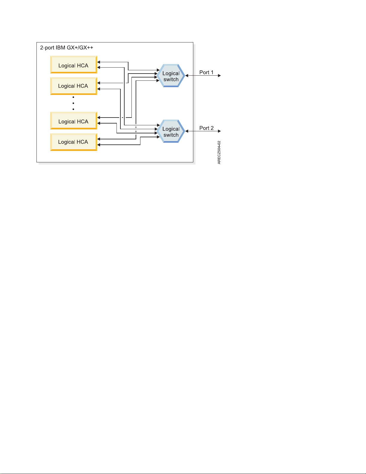
Figure 5. Two-port GX or GX+ host channel adapter
A four-port HCA has two chips with a total of four logical switches that has two logical switches in each
of the two chips.
The logical structure affects how the HCA is represented to the Subnet Manager. Each logical switch and
LHCA represent a separate InfiniBand node to the Subnet Manager on each port. Each LHCA connects to
all logical switches in the HCA.
Each logical switch has a port globally unique identifier (GUID) for the physical port and a port GUID
for each LHCA. Each LHCA has two port GUIDs, one for each logical switch.
The number of nodes that can be presented to the Subnet Manager is a function of the maximum number
of LHCAs that are assigned. This is a configurable number for POWER6 GX HCAs, and it is a fixed
number for System p POWER5
™
GX HCAs. The Power hypervisor (PHyp) communicates with the Subnet
Manager using the Subnet Management Agent (SMA) function in phyp.
The POWER6 GX HCA supports a single LHCA by default. In this case, the GX HCA presents each
physical port to the Subnet Manager as a two-port logical switch. One port is connected to the LHCA and
the second port is connected to the physical port. The POWER6 GX HCA can also be configured to
support up to 16 LHCAs. In this case, the HCA presents each physical port to the Subnet Manager as a
17-port logical switch with up to 16 LHCAs. Ultimately, the number of ports for a logical switch is
dependent on the number of logical partitions concurrently using the GX HCA.
The POWER5 GX HCA supports up to 64 LHCAs. In this case, the GX HCA presents each physical port
to the Subnet Manager as a 65-port logical switch. One port connects to the physical port and 64 ports
connect to LHCAs. As compared to how it works on POWER6 processor-based systems, for System p
POWER5 processor-based systems, it does not matter how many LHCAs are defined and used by logical
partitions. The number of nodes presented includes all potential LHCAs for the configuration. Therefore,
each physical port on a GX HCA in a POWER5 processor-based system presents itself as a 65-port logical
switch.
The Hardware Management Console (HMC) that manages the server, in which the HCA is populated, is
used to configure the virtualization capabilities of the HCA. For systems that are not managed by an
HMC, configuration and virtualization are done using the Integrated Virtualization Manager (IVM).
Each logical partition is only aware of its assigned LHCA. For each logical partition profile, a GUID is
selected with an LHCA. The GUID is programmed in the adapter and cannot be changed.
8 Power Systems: High performance clustering
Page 25

Since each GUID must be different in a network, the IBM HCA gets a subsequent GUID assigned by the
firmware. You can choose the offset that is used for the LHCA. This information is also stored in the
logical partition profile on the HMC.
Therefore, when an HCA is replaced, each logical partition profile must be manually updated with the
new HCA GUID information. If this step is not performed, the HCA is not available to the operating
system.
The following table describes how the HCA resources are allocated to a logical partition. This ability to
allocate HCA resources permits multiple logical partitions to share a single HCA. The degree of sharing is
driven by your application requirements.
The Dedicated value is only used when you have a single, active logical partition that must use all the
available HCA resources. You can configure multiple logical partitions to be dedicated, but only one can
be active at a time.
When you have more than one logical partition sharing an HCA, you can change to high, medium, or
low allocation to it. You can never allocate more than 100% of the HCA across all active logical partitions.
For example, four active logical partitions can be set to medium and two active logical partitions can be set
to High; (4x1/8) + (2x1/4) = 1.
If the requested resource allocation for an LPAR exceeds the available resource for an HCA, the LPAR
fails to activate. So, in the preceding example with six active LPARs, if one more LPAR tried to activate
and use the HCA, the LPAR would fail to activate, because the HCA is already 100% allocated
Table 7. Allocation of HCA resources to a logical partition
Value Resulting resource allocation or adapter
Dedicated All of the adapter resources are dedicated to the LPAR. This value is
the default for single LPARs, which is the supported HPC Cluster
configuration.
If you have multiple active LPARs, you cannot simultaneously
dedicate the HCA to more than one active LPAR.
High One-quarter of the maximum adapter resources
Medium One-eighth of the maximum adapter resources
Low One-sixteenth of maximum adapter resources
Logical switch naming convention:
The IBM GX host channel adapters (HCAs) have a logical switch naming convention based on the server
type and the HCA type.
The following table shows the logical switch naming convention.
Table 8. Logical switch naming convention
Server HCA chip base Logical switch name
POWER5 Any IBM Logical Switch 1 or IBM Logical
Switch 2
System p (POWER6) First generation IBM G1 Logical Switch 1 or IBM G1
Logical Switch 2
System p (POWER6) Second generation IBM G2 Logical Switch 1 or IBM G2
Logical Switch 2
High-performance computing clusters using InfiniBand hardware 9
Page 26

Host channel adapter statistics counter:
The statistics counters in the IBM GX host channel adapters (HCAs) are only available with HCAs in
System p (POWER6) servers.
You can query the counters using Performance Manager functions with the Fabric Viewer and the fast
fabric iba_report command. For more information see, “Hints on using iba_report” on page 180. While
the HCA tracks most of the prescribed counters, it does not have counters for transmit packets or receive
packets.
Related reference
“Hints on using iba_report” on page 180
The iba_report function helps you to monitor the cluster fabric resources.
Vendor and IBM switches
In older Power clusters, vendor switches might be used as the backbone of the communications fabric in
an IBM HPC Cluster using InfiniBand technology. These are all based on the 24 port Mellanox chip.
IBM has released a machine type and models based on the QLogic 9000 series. All new clusters are sold
with these switches.
QLogic switches supported by IBM
IBM supports QLogic switches in high-performance computing (HPC) clusters.
The following QLogic switch models are supported. For more details on the models, see the QLogic
documentation and the Users guide for the switch model, which are available at http://
www.qlogic.com/Pages/default.aspx or contact QLogic support.
Note: QLogic uses SilverStorm in their product names.
Table 9. InfiniBand switch models
Number of ports IBM Switch Machine Type-Model QLogic Switch Model
24 7874-024 9024 = 24 port
48 7874-040 9040 = 48 port
96 N/A* 9080 = 96 port
144 7874-120 9120 = 144 port
288 7872-240 9240 = 288 port
* IBM does not implement a 96 port 7874 switch.
Cables
IBM supports specific cables for high-performance computing (HPC) cluster configurations.
The following table describes the cables that are supported for IBM HPC configurations.
10 Power Systems: High performance clustering
Page 27

Table 10. Cables for high-performance computing configurations
Comments(feature
codes listed in order
System or use Cable type Connector type Length - m (ft) Source
POWER6
9125-F2A
POWER6
8204-E8A,
8203-E4A,
9119-FHA,
9117-MMA
POWER7
8236-E8C
JS22 4x DDR, copper CX4 - CX4 Multiple lengths Vendor To connect between
Inter-switch 4x DDR, copper CX4 - CX4 Multiple lengths Vendor For use between
Inter-switch 4x DDR, optical CX4 - CX4 Multiple lengths Vendor For use between
®
4x DDR, copper QSFP - CX4 6 m (passive, 26
awg),
10 m (active, 26
awg),
14 m (active, 30
awg)
4x DDR, optical QSFP - CX4 10 m, 20 m, 40 m IBM IBM feature codes:
12x - 4x DDR
width exchanger,
copper
CX4 - CX4 3 m,
10 m
QLogic
IBM Link operates at 4x
respective to length)
3291, 3292, 3294
speed.
IBM feature codes:
1841, 1842
PTM and switch.
switches.
switches. Feature codes
are for the IBM system
type 7874 switch.
7874 IBM Feature
Codes 3301, 3302, 3300
Fabric
management
server
4x DDR, copper CX4 - CX4 Multiple lengths Vendor For connecting the
4x DDR, optical CX4 - CX4 Multiple lengths Vendor
fabric management
server to subnet to
support host-based
Subnet Manager and
Fast Fabric Toolset.
Subnet Manager
The Subnet Manager is defined by the InfiniBand standard specification. It is used to configure and
manage the communication fabric so that it can pass data. It does in-band management over the same
links as the data.
The Subnet Manager is defined by the standard specification. Management functions are performed
inband over the same links as the data.
Use a host-based Subnet Manager (HSM) which runs a Fabric Management Server. The host-based Subnet
Manager scales better than the embedded Subnet Manager (ESM), and IBM has verified and approved
the HSM for use in High Performance Computing (HPC) clusters.
For more information about Subnet Managers, see the InfiniBand standard specification or vendor
documentation.
High-performance computing clusters using InfiniBand hardware 11
Page 28

Related concepts
“Management subsystem function overview” on page 13
This information provides an overview of the servers, consoles, applications, firmware, and networks that
comprise the management subsystem function.
POWER Hypervisor
The POWER Hypervisor™provides an abstraction layer between the hardware and firmware and the
operating system instances.
POWER Hypervisor provides the following functions in POWER6 GX HCA implementations.
v UD low latency receive queues
v Large page memory sizes
v Shared receive queues (SRQ)
v Support for more than 16 K Queue Pairs (QP). The exact number of QPs is driven by cluster size and
available system memory.
POWER Hypervisor also contains the Subnet Management Agent (SMA) to communicate with the Subnet
Manager and present the HCA as logical switches with a given number of ports attached to the physical
ports and to logical HCAs (LHCAs).
POWER Hypervisor also contains the Performance Management Agent (PMA), which is used to
communicate with the performance manager that collects fabric statistics, such as link statistics, including
errors and link usage statistics. The QLogic Fast Fabric iba_report command uses performance manager
protocol to collect error and performance counters.
If there are logical HCAs, the performance manager packet first goes to the operating system driver. The
operating system replies to the requestor that it must redirect its request to the Hypervisor. Because of
this added traffic for redirection and the Logical HCA counters are of little practical use, it is advised that
the Logical HCA counters are normally not collected.
For more information about SMA and PMA function, see the InfiniBand architecture documentation.
Related concepts
“IBM GX+ or GX++ host channel adapter” on page 7
The IBM GX or GX+ host channel adapter (HCA) provides server connectivity to InfiniBand fabrics.
Device drivers
IBM provides device drivers for the AIX operating system. Device drivers for the Linux operating system
are provided by the distributors.
The vendor provides the device driver that is used on Fabric Management Servers.
Related concepts
“Management subsystem function overview” on page 13
This information provides an overview of the servers, consoles, applications, firmware, and networks that
comprise the management subsystem function.
IBM host stack
The high-performance computing (HPC) software stack is supported for IBMSystem p HPC Clusters.
The vendor host stack is used on Fabric Management Servers.
12 Power Systems: High performance clustering
Page 29

Related concepts
“Management subsystem function overview”
This information provides an overview of the servers, consoles, applications, firmware, and networks that
comprise the management subsystem function.
Management subsystem function overview
This information provides an overview of the servers, consoles, applications, firmware, and networks that
comprise the management subsystem function.
The management subsystem is a collection of servers, consoles, applications, firmware, and networks that
work together to provide the following functions.
v Installing and managing the firmware on hardware devices
v Configuring the devices and the fabric
v Monitoring for events in the cluster
v Monitoring status of the devices in the cluster
v Recovering and routing around failure scenarios in the fabric
v Diagnosing the problems in the cluster
IBM and vendor system and fabric management products and utilities can be configured to work
together to manage the fabric.
Review the following information to better understand InfiniBand fabrics.
v The InfiniBand standard specification from the InfiniBand Trade Association. Read the information
about managers.
v Documentation from the switch vendor. Read the Fabric Manager and Fast Fabric Toolset
documentation.
Related concepts
“Cluster information resources” on page 2
The following tables indicate important documentation for the cluster, where to get it and when to use it
relative to Planning, Installation, and Management and Service phases of a clusters life.
Management subsystem integration recommendations
Extreme Cloud Administration Toolkit (xCAT) is the IBM Systems Management tool that provides the
integration function for InfiniBand fabric management.
The major advantages of xCAT in a cluster are as follows.
v The ability to issue remote commands to many nodes and devices simultaneously.
v The ability to consolidate logs and events from many sources in a cluster by using event management.
The IBM System p HPC clusters are migrating from CSM to xCAT. With respect to solutions using
InfiniBand, the following table translates key terms, utilities, and file paths from CSM to xCAT:
Table 11. CSM to xCAT translations
CSM xCAT
dsh xdsh
/var/opt/csm/IBSwitches/Qlogic/config /var/opt/xcat/IBSwitch/Qlogic/config
/var/log/csm/errorlog /tmp/systemEvents
/opt/csm/samples/ib /opt/xcat/share/xcat/ib/scripts
IBconfigAdapter script configiba
The term “node” device
High-performance computing clusters using InfiniBand hardware 13
Page 30

QLogic provides the following switch and fabric management tools.
v Fabric Manager (From level 4.3, onward, is part of the QLogic InfiniBand Fabric Suite (IFS). Previously,
it was in its own package.)
v Fast Fabric Toolset (From level 4.3, onward, is part of QLogic IFS. Previously, it was in its own
package.)
v Chassis Viewer
v Switch command-line interface
v Fabric Viewer
Management subsystem high-level functions
Several high-level functions address management subsystem integrations.
To address the management subsystem integration, functions for management are divided into the
following topics:
1. Monitor the state and health of the fabric
2. Maintain
3. Diagnose
4. Connectivity
Monitor
You can use the following functions to monitor the state and health of the fabric:
1. Syslog entries (status and configuration changes) can be forwarded from the Subnet Managers to the
xCAT Management Server (MS). Set up different files to separate priority and severity.
2. The IBSwitchLogSensor within xCAT can be configured.
3. The QLogic Fast Fabric Toolset health checking tools can be used for regularly monitoring the fabric
for errors and configuration changes that might lead to performance problems.
Maintain
The xdsh command in xCAT permits you to use the following vendor command-line tools remotely:
1. Switch chassis command-line interface (CLI) on a managed switch.
2. Subnet Manager running in a switch chassis or on a host.
3. Fast Fabric tools running on a fabric management server or host. This host is an IBM System x server
that is running on the Linux operating system and the host stack from the vendor.
Diagnosing
Vendor tools diagnose the health of the fabric.
The QLogic Fast Fabric Toolset running on the Fabric Management Server or Host provides the main
diagnostic capability. It is important when there are no obvious errors, but there is an observed
degradation in performance. This degradation might be a result of errors previously undetected or
configuration changes including missing resources.
Connecting
For connectivity, the xCAT/MS must be on the same cluster VLAN as the switches and the fabric
management servers that is running the Subnet Managers and Fast Fabric tools.
14 Power Systems: High performance clustering
Page 31
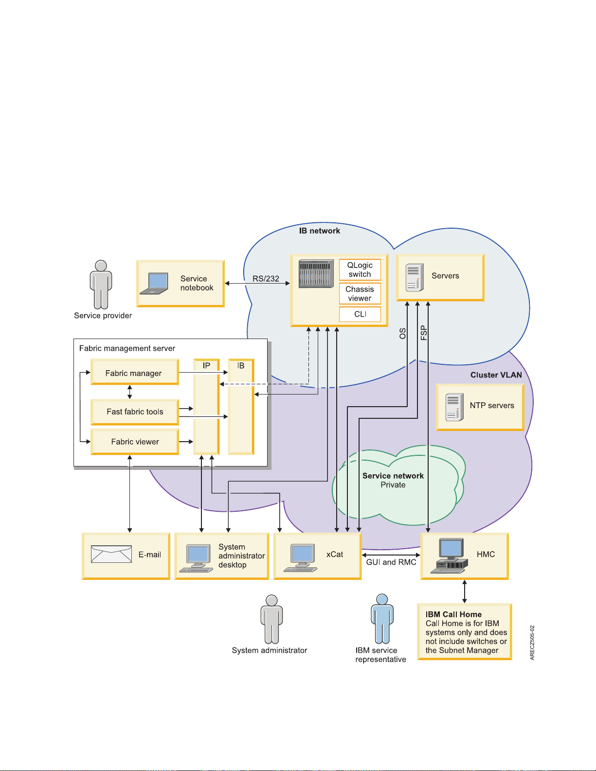
Management subsystem overview
The management subsystem in the System p HPC Cluster solution using an InfiniBand fabric loosely
integrates the typical IBM System p HPC cluster components with the QLogic components.
The management subsystem can be viewed from several perspectives, including:
v Host views
v Networks
v Functional components
v Users and interfaces
The following figure illustrates the functions of the management or service subsystem.
Figure 6. Management subsystem
High-performance computing clusters using InfiniBand hardware 15
Page 32

The preceding figure illustrates the use of a host-based Subnet Manager (HSM), rather than an embedded
Subnet Manager (ESM), running on a switch. This use of HSM is because of the limited compute
resources on switches for ESM use. If you are using an ESM, then the Fabric Managers runs on switches.
The servers are monitored and serviced in the same fashion as for any IBM Power Systems cluster.
The following table is a quick reference for the various management hosts or consoles in the cluster
including who is intended to use them, and the networks to which they are connected.
Table 12. Management subsystem server, consoles, and workstations
Hosts Software hosted Server type Operating system User Connectivity
xCAT/MS xCAT IBM System p
IBM System x
Fabric
management
server
Hardware
Management
Console (HMC)
Switch
System
administrator
workstation
v Fast Fabric
Tools
v Host-based
Fabric Manager
(recommended)
v Fabric viewer
(optional)
Hardware
Management
Console for
managing IBM
systems.
v Chassis
firmware
v Chassis viewer
v Embedded
Fabric Manager
(optional)
v System
administrator
workstation
v Fabric viewer
(optional)
v Launch point
into
management
servers
Note: This
launch point
requires
network access
to other
servers.
(optional)
IBM System x Linux
IBM System x Proprietary
Switch chassis Proprietary
User preference User preference System
AIX
Linux
Admin
v System
administrator
v Switch service
provider
v IBM CE
v System
administrator
v System
administrator
v Switch service
provider
administrator
v Cluster virtual
local area
network
(VLAN)
v Service VLAN
v InfiniBand
v Cluster VLAN
(same as
switches)
v Service VLAN
v Cluster VLAN
or public
VLAN
(optional)
Cluster VLAN
(Chassis viewer
requires public
network access)
Network access to
management
servers
16 Power Systems: High performance clustering
Page 33

Table 12. Management subsystem server, consoles, and workstations (continued)
Hosts Software hosted Server type Operating system User Connectivity
Service laptop Serial interface to
switch
Note: This is not
provided by IBM
as part of the
cluster. It is
provided by the
user or the site.
NTP server NTP Site preference Site preference Not applicable
Laptop User experience
v Switch service
provider
v System
administrator
RS/232 to switch
v Cluster VLAN
v Service VLAN
xCAT:
Extreme Cluster Administration Toolset. xCAT is a system administrator tool for monitoring and
managing the cluster.
The following table provides an overview of xCAT.
Table 13. xCAT overview
Description Extreme Cluster Administration Toolset. xCAT is used by the system admin to monitor
and manage the cluster.
Documentation xCAT documentation
When to use For the fabric, use xCAT to:
v Monitor remote logs from the switches and Fabric Management Servers
v Remotely run commands on the switches and Fabric Management Servers
After configuring the switches and Fabric Management Servers IP addresses, remote
syslogging and creating them as devices, xCAT can be used to monitor for switch
events, and xdsh to their CLI.
Host xCAT Management Server
How to access Use CLI or GUI on the xCAT Management Server.
Fabric manager:
The fabric manager is used to complete basic operations such as fabric discovery, fabric configuration,
fabric monitoring, fabric reconfiguration after failure, and reporting problems.
The following table provides an overview of the fabric manager.
High-performance computing clusters using InfiniBand hardware 17
Page 34

Table 14. Fabric manager overview
Fabric manager Details
Description The fabric manager performs the following basic operations:
v Discovers fabric devices
v Configures the fabric
v Monitors the fabric
v Reconfigures the fabric on failure
v Reports problems
The fabric manager has several management interfaces that are used to manage an
InfiniBand network. These interfaces include the baseboard manager, performance
manager, Subnet Manager, and fabric executive. All but the fabric executives are
described in the InfiniBand architecture. The fabric executive is there to provide an
interface between the Fabric Viewer and the other managers. Each of these managers is
required to fully manage a single subnet. If you have a host-based fabric manager, there
is up to 4 fabric managers on the Fabric Manager Server. Configuration parameters for
each of the managers for each instance of fabric manager must be considered. There are
many parameters, but only a few typically varies from default.
A more detailed description of fabric management is available in the InfiniBand standard
specification and vendor documentation.
Documentation
When to use Fabric management cab be used to manage the network and pass data. You use the
Host
How to access You might access the Fabric Manager functions from xCAT by remote commands
v QLogic Fabric Manager Users Guide
v InfiniBand standard specification
Chassis Viewer, CLI, or Fabric Viewer to interact with the fabric manager.
v Host-based fabric manager is on the fabric management server.
v Embedded fabric manager is on the switch.
through dsh to the Fabric Management Server or switch, on which the embedded fabric
manager is running. You can access many instances using xdsh.
For host-based fabric managers, log on to the Fabric Management Server.
For embedded fabric managers, use the Chassis Viewer, switch CLI, Fast Fabric Toolset,
or Fabric Viewer to interact with the fabric manager.
Hardware Management Console:
You can use the Hardware Management Console (HMC) to manage a group of servers.
The following table provides an overview of the HMC.
Table 15. HMC overview
HMC Details
Description Each HMC is assigned to the management of a group of servers. If there is more than
one HMC in a cluster, then it is accomplished by using the Cluster Ready Hardware
Server on the cluster management server.
Documentation HMC Users Guide
When to use To set up and manage LPARs, including HCA virtualization. To access Service Focal
Host HMC
™
for HCA and server reported hardware events. To control the server hardware.
Point
18 Power Systems: High performance clustering
Page 35

Table 15. HMC overview (continued)
HMC Details
How to access Use the HMC console located near the system. There is generally a single keyboard and
monitor with a console switch to access multiple HMCs in a rack (if there is a need for
multiple HMCs).
You can also access the HMC through a supported web browser on a remote server that
can connect to the HMC.
Switch chassis viewer:
The switch chassis viewer is a tool that is used to configure a switch and query the state of the switch.
The following table provides an overview of the switch chassis viewer.
Table 16. Switch chassis viewer overview
Switch chassis viewer Details
Description The switch chassis viewer is a tool for configuring a switch and a tool for querying its
state. It is also used to access the embedded fabric manager. Since it can only work with
one switch at a time, it does not scale well.
Documentation Switch Users Guide
When to use After the configuration setup has been performed, the user will probably only use the
chassis viewer as part of diagnostic test. This diagnostic test is used after the Fabric
Viewer or Fast Fabric tools have been employed and isolated a problem to a chassis.
Host Switch chassis
How to access The Chassis Viewer is accessible through any browser on a server connected to the
Ethernet network to which the switch is attached. The IP address of the switch is the
URL that opens the chassis viewer.
Switch command-line interface:
Use the switch command-line interface (CLI) for configuring switches and querying the state of a switch.
The following table provides an overview of the switch chassis viewer.
Table 17. Switch CLI overview
Switch command-line interface Details
Description The Switch Command Line Interface is a non-GUI method for configuring switches and
querying state. It is also used to access the embedded Subnet Manager.
Documentation Switch Users Guide
When to use After the configuration setup has been performed, the user will probably only use the
CLI chassis viewer as part of diagnostic test. This diagnostic test is used after the Fabric
Viewer or Fast Fabric tools have been employed. However, using xCAT xdsh or Expect,
remote scripts can access the CLI for creating customized monitoring and management
scripts.
Host Switch Chassis
How to access
v Telnet or ssh to the switch using its IP address on the cluster VLAN
v Fast Fabric Toolset
v xdsh from the xCAT/MS
v System connected to the RS/232 port
High-performance computing clusters using InfiniBand hardware 19
Page 36

Server Operating system:
The operating system is the interface with the device drivers.
The following table provides an overview of the operating system.
Table 18. Operating system overview
Operating system details More information
Description The operating system is the interface for the device drivers.
Documentation Operating system users guide
When to use To query the state of the host channel adapters (HCAs) and the availability of the HCAs
to applications.
Host IBM system
How to access xdsh from xCAT or telnet/ssh into the LPAR.
Network Time Protocol:
The Network Time Protocol (NTP) synchronizes the clocks in the management servers and switches.
The following table provides an overview of the NTP.
Table 19. Network Time Protocol overview
Network Time Protocol Details
Description The NTP is used to keep the switches and management servers time of day clocks
synchronized. It is important to ensure the correlation of events in time.
Documentation NTP Users Guide
When to use The NTP is set up during installation.
Host The NTP Server
How to access The administrator accesses the NTP by logging on to the system on which the NTP
server is running. The NTP is accessed for configuration and maintenance and usually is
a background application.
Fast Fabric Toolset:
The QLogic Fast Fabric Toolset is a set of scripts that are used to manage switches and to obtain
information about the switch status.
The following table provides an overview of the Fast Fabric Toolset.
Table 20. Fast Fabric Toolset overview
Fast Fabric Toolset Details
Description Fast Fabric tools are a set of scripts that provide access to switches and the various
managers to connect with many switches. And the managers simultaneously obtain
useful status or information. Additionally, health-checking tools help you to identify
fabric error states and also unforeseen changes from baseline configuration. Health
checking tools are run from a central server called the fabric management server.
These tools can also help manage nodes running the QLogic host stack. The set of
functions that manages nodes are not used with an IBM System p or IBM Power
Systems high-performance computing (HPC) cluster.
20 Power Systems: High performance clustering
Page 37

Table 20. Fast Fabric Toolset overview (continued)
Fast Fabric Toolset Details
Documentation Fast Fabric Toolset Users Guide
When to use These tools can be used during installation to search for problems. These tools can also
be used for health checking when you have degraded performance.
Host Fabric management server
How to access
v Telnet or ssh to the Fabric Management Server
v If you set up the server that is running the Fast Fabric tools as a managed device, you
can use xdsh command for xCAT.
Flexible Service processor:
The Flexible service processor is used to facilitate connectivity.
The following table provides an overview of the flexible service processor.
Table 21. Flexible Service processor overview
Service processor Details
Description Cluster management server and the managing HMC must be able to communicate with
the FSP over the service VLAN. For system type 9125 servers, connectivity is facilitated
through an internal hardware virtual local area network (VLAN) within the frame,
which connects to the service VLAN.
Documentation IBM System Users Guide
When to use The FSP is in the background most of the time and the HMC and management server
provide the information. It is sometimes accessed under direction from engineering.
Host IBM system
How to access Is primarily used by service personnel. Direct access is rarely required, and is done
under direction from engineering using the ASMI screens. Otherwise, management
server and the HMC are used to communicate with the FSP.
Fabric viewer:
The fabric viewer is an interface that is used to access the Fabric Management tools.
The following table provides an overview of the fabric viewer.
Table 22. Fabric viewer overview
Fabric viewer Details
Description The fabric viewer is a user interface that is used to access the Fabric Management tools
on the various subnets. It is a Linux or Microsoft Windows application.
The fabric viewer must be able to connect to the cluster virtual local area network
(VLAN) to connect to the switches. The fabric viewer must also connect to the Subnet
Manager hosts through the same cluster VLAN.
Documentation QLogic Fabric Viewer Users Guide
When to use After you have setup the switch for communication to the Fabric Viewer this can be
used as the main point for queries and interaction with the switches. You will also use
this to update the switch code simultaneously to multiple switches in the cluster. You
will also use this during install time to set up Email notification for link status changes
and SM and EM communication status changes.
High-performance computing clusters using InfiniBand hardware 21
Page 38

Table 22. Fabric viewer overview (continued)
Fabric viewer Details
Host Any Linux or Microsoft Windows host. Typically, these hosts would be one of the
following items.
v Fabric management server
v System administrator or operator workstation
How to access Start the graphical user interface (GUI) from the server on which you install the fabric
viewer, or use a remote window access to start it. VNC is an example of a remote
window access application.
Email notifications:
The email notifications function can be enabled to trigger emails from the fabric viewer.
The following table provides an overview of email notifications.
Table 23. Email notifications overview
Email notifications Details
Description A subset of events can be enabled to trigger an email from the Fabric Viewer. These are
link up and down and communication issues between the Fabric Viewer and parts of the
fabric manager.
Typically Fabric Viewer is used interactively and shutdown after a session. This would
prevent the ability to effectively use email notification. If you want to use this function,
you must have a copy of Fabric Viewer running continuously; for example, on the Fabric
Management Server.
Documentation Fabric Viewer Users Guide
When to use Set up during installation so that you can be notified of events as they occur.
Host Wherever Fabric Viewer is running.
How to access Setup for email notification is done on the fabric viewer. The email is accessed from
wherever you have directed the fabric viewer to send the email notifications.
Management subsystem networks:
The devices in the management subsystem are connected through various networks.
All of the devices in the management subsystem are connected to at least two networks over which their
applications must communicate. Typically, the site connects key servers to a local network to provide
remote access for managing the cluster. The networks are shown in the following table.
Table 24. Management subsystem networks overview
Type of network Details
Service VLAN The service VLAN is a private Ethernet network which provides connectivity between
the FSPs, BPAs, xCAT/MS, and the HMCs to facilitate hardware control.
Cluster VLAN The cluster VLAN (or network) is an Ethernet network (public or private), which gives
xCAT access to the operating systems. It is also used for access to InfiniBand switches
and fabric management servers.
Note: The switch vendor documentation references to the Cluster VLAN as the service
VLAN, or possibly the management network.
22 Power Systems: High performance clustering
Page 39

Table 24. Management subsystem networks overview (continued)
Type of network Details
Public network A local site Ethernet network. Typically this network is attached to the xCAT/MS and
Fabric Management Server. Some sites might choose to put the cluster VLAN on the
public network. See the xCAT installation and planning documentation to consider the
implications of combining these networks.
Internal hardware VLAN Is a virtual local area network (VLAN) within a frame of 9125 servers. It concentrates all
server FSP connections and the BPH connections onto an internal ethernet hub, which
provides a single connection to the service VLAN, which is external to the frame.
Vendor log flow to xCAT event management
The integration of vendor and IBM log flows is a critical factor in event management.
One of the important points of integration for vendor and IBM management subsystems is log flow from
vendor management applications to xCAT event management. This integration provides a consolidated
logging point in the cluster. The flow of log information is shown in the following figure. For this
integration to work, you must set up remote logging and xCAT event management with the Fabric
Management Server and the switches as described in “Set up remote logging” on page 112.
The figure indicates where remote logging and xCAT Sensor-Condition-Response must be enabled for the
flow to work.
There are three standard response outputs shipped with xCAT. Refer the xCAT Monitoring How-to
documentation for more details on event management. For this flow, xCAT uses the IBSwitchLogSensor
and the LocalIBSwitchLog condition and one or more of the following responses: Email root anytime,
Log event anytime, and LogEventToxCATDatabase.
High-performance computing clusters using InfiniBand hardware 23
Page 40
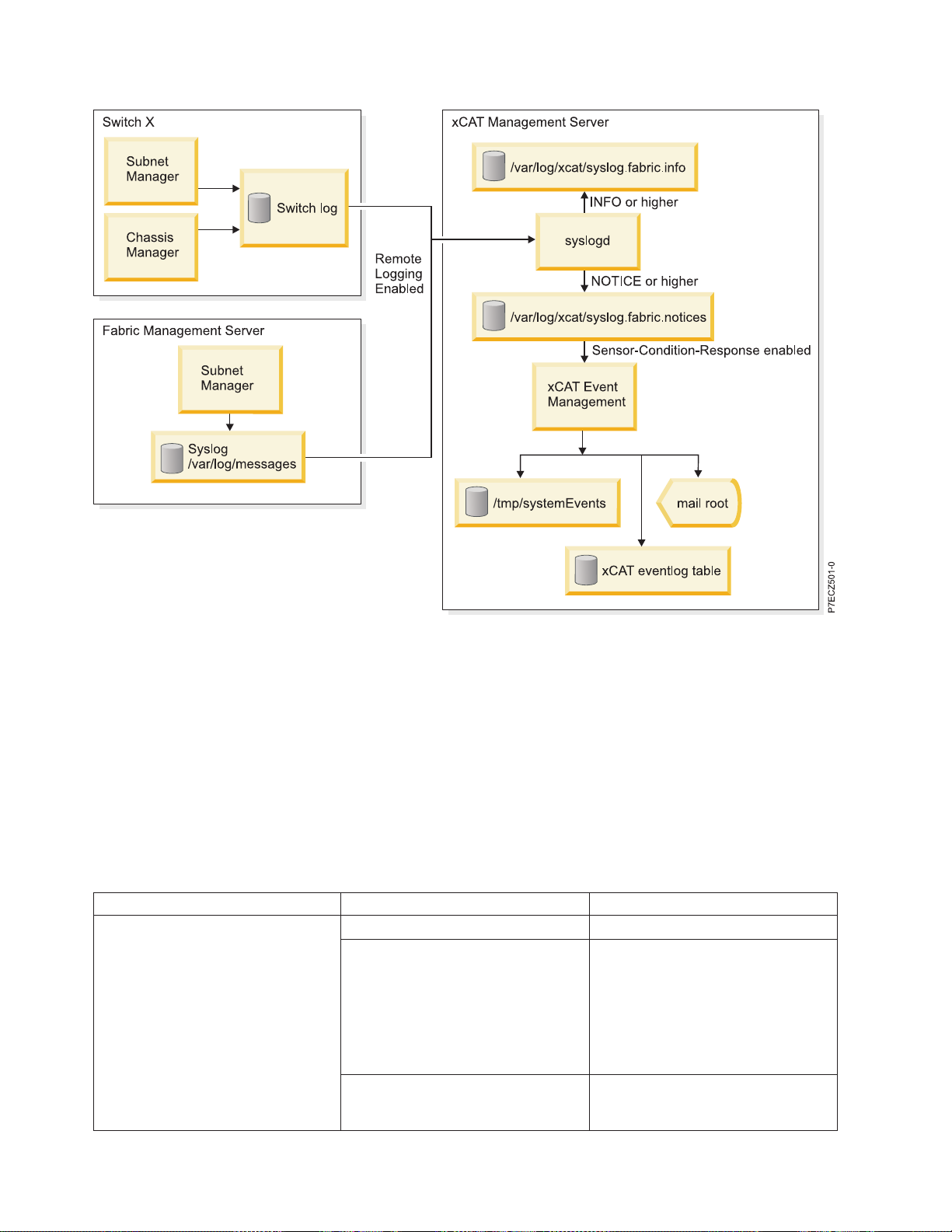
Figure 7. Vendor log flow to xCAT event management
Supported components in an HPC cluster
High-performance computing (HPC) clusters are implemented using components that are approved and
supported by IBM.
For details, see “Cluster information resources” on page 2.
The following table indicates the components or units that are supported in an HPC cluster as of Service
Pack 10.
Table 25. Supported HPC components
Component type Component Model, feature, or minimum level
POWER6 processor-based servers
POWER7 (8236)
2U high-end server 9125-F2A
High volume server 4U high 8203-E4A
8204-E8A
Only IPoIB is supported on the 8203
and 8204.
8236-755 (full IB support)
Blade Server Model JS22: 7988-61X
24 Power Systems: High performance clustering
Model JS23: 7778-23X
Page 41

Table 25. Supported HPC components (continued)
Component type Component Model, feature, or minimum level
Operating system AIX 5L
™
AIX 5.3 at Technology Level 5300-12
with Service Pack 1
AIX 5.3 is for POWER6 only
AIX 6.1 POWER6:
AIX Version 6.1 with the 6100-01
Technology Level with Service Pack 1
POWER7 AIX 6LVersion 6.1 with the
6100-04 Technology Level with
Service Pack 2
RedHat RHEL Red Hat 5.3 ppc kernel-2.6.18-
128.2.1.el5.ppc64
Switch QLogic (for existing customers only) 9024, 9040, 9080, 9120, 9240
IBM 7874-024, 7874-040, 7874-120, 7874-240
IBM GX HCAs IBM GX+ HCA for 9125-F2A 5612
IBM GX HCA for 8203-E4A and
5616 = SDR HCA
8204-E8A
5608,5609 = DDR HCA
IBM GX HCA for 8236-E8C 5609 = DDR HCA
JS22/JS23 HCA Mellanox 4x Connect-X HCA 8258
JS22/JS23 Pass-thru module Voltaire High Performance InfiniBand
3216
Pass-Through Module for IBM
BladeCenter
Cable CX4 to CX4 For Information, see“Cables” on page
10
QSFP to CX4 For Information, see“Cables” on page
10
Management node for InfiniBand
fabric
IBM System x 3550 (1U high) 7978AC1
IBM System x 3650 (2U high) 7979AC1
HCA for management node QLogic Dual-Port 4X DDR
InfiniBand PCIe HCA
QLogic InfiniBand Fabric Suite Fabric
Manager
QLogic host-based Fabric Manager
(embedded not preferred
5.0.3.0.3
QLogic-OFED host stack
Fast Fabric Toolset
Switch firmware QLogic firmware for the switch 4.2.4.2.1
xCAT AIX or Linux 2.3.3
High-performance computing clusters using InfiniBand hardware 25
Page 42

Table 25. Supported HPC components (continued)
Component type Component Model, feature, or minimum level
Hardware Management Console
(HMC)
HMC POWER6:
V7R3.5.0M0 HMC with fixes
MH01194, MH01197, MH01204, and
V7R3.5.0M1 HMC with MH01212
(HMC build level: 20100301.1)
POWER7:
V7R7.1.1 HMC with Fix pack
AL710_03
Cluster planning
Plan a cluster that uses InfiniBand technologies for the communications fabric. This information covers
the key elements of the planning process, and helps you organize existing, detailed planning information.
When planning a cluster with an InfiniBand network, you bring together many different devices and
management tools to form a cluster. The following are major components that are part of a cluster.
v Servers
v I/O devices
v InfiniBand network devices
v Frames (racks)
v Service virtual local area network (VLAN) that includes the following items.
– Hardware Management Console (HMC)
– Ethernet devices
– xCAT Management Server
v Management Network that includes the following items.
– xCAT Management Server
– Servers to provide operating system access from the CAT
– InfiniBand switches
– Fabric management server
– AIX Network Installation Management (NIM) server (for servers with no removable media)
– Linux distribution server (for servers with no removable media)
v System management applications that include the following items.
– HMC
– xCAT
– Fabric Manager
– Other QLogic management tools such as Fast Fabric Toolset, Fabric Viewer and Chassis Viewer
v Physical characteristics such as weight and dimensions
v Electrical characteristics
v Cooling characteristics
The “Cluster information resources” on page 2 provide the required documents and other Internet
resources that help you plan your cluster. It is not an exhaustive list of the documents that you need, but
it would provide a good launch point for gathering required information.
26 Power Systems: High performance clustering
Page 43

The “Cluster planning overview” can be used as a road map through the planning process. If you read
through the Cluster planning overview without following the links, you gain an understanding of the
overall cluster planning strategy. Then you can follow the links that direct you through the different
procedures to gain an in-depth understanding of the cluster planning process.
In the Cluster planning overview, the planning procedures are arranged in a sequential order for a new
cluster installation. If you are not installing a new cluster, you must choose which procedures to use.
However, you would still perform them in the order they appear in the Cluster planning overview. If you
are using the links in “Cluster planning overview,” note when a planning procedure ends so that you
know when to return to the “Cluster planning overview.” The end of each major planning procedure is
indicated by “[planning procedure name] ends here”.
Cluster planning overview
Use this information as a road map to through the cluster planning procedures.
To plan your cluster complete the following tasks.
1. Gather and review the planning and installation information for the components in the cluster.
See“Cluster information resources” on page 2 as a starting point for where to obtain the information.
This information provides supplemental documentation with respect to clustered computing with an
InfiniBand network. You must understand all of the planning information for the individual
components before continuing with this planning overview.
2. Review the “Planning checklist” on page 75 which can help you track the planning steps that you
have completed.
3. Review the “Required level of support, firmware, and devices” on page 28 to understand the
minimal level of software and firmware required to support clustering with an InfiniBand network.
4. Review the planning resources for the individual servers that you want to use in your cluster. See
“Server planning” on page 29.
5. Review “Planning InfiniBand network cabling and configuration” on page 30 to understand the
network devices and configuration. The planning information addresses the following items.
v “Planning InfiniBand network cabling and configuration” on page 30.
v “Planning an IBM GX HCA configuration” on page 53. For vendor host channel adapter (HCA)
planning, use the vendor documentation.
6. Review the “Management subsystem planning” on page 54. The management subsystem planning
addresses the following items.
v Learning how the Hardware Management Console works in a cluster
v Learning about Network Installation Management (NIM) servers (AIX) and distribution servers
(Linux)
v “Planning your Systems Management application” on page 55
v “Planning for QLogic fabric management applications” on page 56
v “Planning for fabric management server” on page 64
v “Planning event monitoring with QLogic and management server” on page 66
v “Planning to run remote commands with QLogic from the management server” on page 67
7. When you understand the devices in your cluster, review “Frame planning” on page 68, to ensure
that you have properly planned where to put devices in your cluster.
8. After you understand the basic concepts for planning the cluster, review the high-level installation
flow information in “Planning installation flow” on page 68. There are hints about planning the
installation, and also guidelines to help you to coordinate between you and the IBM Service
Representative responsibilities and vendor responsibilities.
9. Consider special circumstances such as whether you are configuring a cluster for high-performance
computing (HPC) message passing interface (MPI) applications. For more information, see “Planning
for an HPC MPI configuration” on page 74.
High-performance computing clusters using InfiniBand hardware 27
Page 44

10. For some more hints and tips on installation planning, see “Planning aids” on page 75.
If you have completed all the previous steps, you can plan in more detail by using the planning
worksheets provided in “Planning worksheets” on page 76.
When you are ready to install the components with which you plan to build your cluster, review
information in readme files and online information related to the software and firmware. This
information ensures that you have the latest information and the latest supported levels of firmware.
If this is the first time you have read the planning overview and you understand the overall intent of the
planning tasks, go back to the beginning and start accessing the links and cross-references to get further
details.
The Planning Overview ends here.
Required level of support, firmware, and devices
Use this information to find the minimum requirements necessary to support InfiniBand network
clustering.
The following tables list the minimum requirements necessary to support InfiniBand network clustering.
Note: For the most recent updates to this information, see the Facts and features report website
(http://www.ibm.com/servers/eserver/clusters/hardware/factsfeatures.html).
Table 26 lists the model or feature that must support the given device.
Table 26. Verified and approved hardware associated with a POWER6 processor-based IBM System p or IBM Power
Systems server cluster with an InfiniBand network
Device Model or feature
Servers POWER6
v IBM Power 520 Express (8203-E4A) (4U rack-mounted server)
v IBM Power 550 Express (8204-E8A) (4U rack-mounted server)
v IBM Power 575 (9125-F2A)
v IBM 8236 System p 755 4U rack-mount servers (8236-E4A)
Switches IBM models (QLogic models)
v QLogic 9024CU Managed 24-port DDR InfiniBand Switch
v QLogic 9040 48-port DDR InfiniBand Switch
v QLogic 9120 144-port DDR InfiniBand Switch
v QLogic 9240 288-port DDR InfiniBand Switch
v There is no IBM equivalent to the QLogic 9080
Host channel adapters
(HCAs)
Fabric management
server
Note:
v High-performance computing (HPC) proven and validated to work in an IBM HPC cluster.
v For approved IBM System p POWER6 and IBM eServer
report website (http://www.ibm.com/servers/eserver/clusters/hardware/factsfeatures.html).
The feature code is dependent on the server you have. Order one or more InfiniBand GX,
dual-port HCA for each server that requires connectivity to InfiniBand networks. The
maximum number of HCAs permitted depends on the server model.
IBM System x 3550 or 3650
QLogic HCAs
™
p5InfiniBand configurations, see Facts and features
28 Power Systems: High performance clustering
Page 45

Table 27 lists the minimum levels of software and firmware that are associated with an InfiniBand cluster.
Table 27. Minimum levels of software and firmware associated with an InfiniBand cluster
Software Minimum level
AIX AIX 5L(TM) AIX 5L Version 5.3 with the 5300-12 Technology Level
with Service Pack 1
AIX 6L(TM) AIX 6L Version 6.1 with the 6100-03 Technology Level
with Service Pack 1
Red Hat 5.3 Red Hat 5.3 ppc kernel-2.6.18-128.1.6.el5.ppc64
Hardware Management Console POWER6 V7R3.5.0M0 HMC with fixes MH01194, MH01197, MH01204,
and V7R3.5.0M1 HMC with MH01212 (HMC build level: 20100301.1)
POWER7 V7R7.1.1 HMC with Fix pack AL710_03
QLogic switch firmware QLogic 4.2.5.0.1
QLogic InfiniBand Fabric Suite (including
the HSM, Fast Fabric Toolset, and
QLogic-OFED stack)
QLogic 5.1.0.0.49
For the most recent support information, see the IBM Clusters with the InfiniBand Switch website.
Required Level of support, firmware, and devices that must support HPC cluster with an InfiniBand network
ends here.
Server planning
This information provides server planning requirements that are relative to the fabric.
Server planning relative to the fabric requires decisions on the following items.
v The number of each type of server you require.
v The type of operating systems running on each server.
v The number and type of host channel adapters (HCAs) that are required in each server.
v Which types of HCAs are required in each server.
v The IP addresses that are needed for the InfiniBand network. For details, see “IP subnet addressing
restriction with RSCT” on page 53.
v The IP addresses that are needed for the service virtual local area network (VLAN) for service
processor access from the xCAT and the Hardware Management Console (HMC)
v The IP addresses for the cluster VLAN to permit operating system access from xCAT
v Which partition assumes service authority. At least, one active partition per server must have the
service authority policy enabled. If multiple active partitions are configured with service authority
enabled, the first one up assumes the authority.
Note: Logical partitioning is not done in high-performance computing (HPC) clusters.
Along with server planning documentation, you can use the “Server planning worksheet” on page 81 as
a planning aid. You can also review server installation documentation to help plan for the installation.
When you have identified the frames in which you plan to place your servers, record the information in
the “Frame and rack planning worksheet” on page 79.
Server types
This information uses the term “server type” to describe the main function that a server is intended to
accomplish.
High-performance computing clusters using InfiniBand hardware 29
Page 46

Server planning relative to the fabric requires decisions on the following items.
Table 28. Server Types in an HPC cluster
Type Description Typical models
Compute Compute servers primarily perform
computation and the main work of
applications.
Storage Storage servers provide connectivity
between the InfiniBand fabric and the
storage devices. This connectivity is a
key part of the GPFS
the cluster.
IO Router IO Router servers provide a bridge
for moving data between separate
networks of servers.
Login Login servers are used to
authenticate users into the cluster. In
order for Login servers to be part of
the GPFS subsystem, they must have
the same number of connections to
the InfiniBand subnets and IP
subnets that are used by the GPFS
subsystem.
™
subsystem in
9125-F2A, 8236-E8C
8203-E4A, 8204-E8A, 9125-F2A,
8236-E8C
9125-F2A, 8236-E8C
Any model
The typical cluster would have compute servers and login nodes. The need for storage servers varies
depending on the application, the wanted performance, and the total size of the cluster. Generally, HPC
clusters with large numbers of servers and strict performance requirements use storage nodes to avoid
contention for compute resource. This setup is especially important for applications that can be easily
affected by the degraded or variable performance of a single server in the cluster.
The use of IO router servers is not typical. There have been examples of clusters where the compute
servers were placed on an entirely different fabric from the storage servers. In these cases, dedicated IO
router servers are used to move the data between the compute and storage fabrics.
For details on how these various server types might be used in fabric, see “Planning InfiniBand network
cabling and configuration.”
Planning InfiniBand network cabling and configuration
Before you plan your InfiniBand network cabling, review the hardware installation and cabling
information for your vendor switch.
See the QLogic documentation referenced in “Cluster information resources” on page 2.
There are several major points in planning network cabling:
v See “Topology planning”
v See “Cable planning” on page 48
v See “Planning QLogic or IBM Machine Type InfiniBand switch configuration” on page 49
v See “Planning an IBM GX HCA configuration” on page 53
Topology planning
This information provides topology planning details.
The following are important considerations for planning the topology of the fabric:
30 Power Systems: High performance clustering
Page 47

1. The types and numbers of servers. See “Server planning” on page 29 and “Server types” on page 29
2. The number of HCA connections in the servers
3. The number of InfiniBand subnets
4. The size and number of switches in each InfiniBand subnet. Do not confuse InfiniBand subnets with
IP subnets. In the context of this topology planning section, unless otherwise noted, the term subnet
refers to an InfiniBand subnet.
5. Planning of the topology with a consistent cabling pattern helps you to determine which server HCA
ports are connected to which switch ports by knowing one side or the other.
If you are planning for a topology that exceeds the generally available topology of 64 servers with up to
eight subnets, contact IBM to help with planning the cluster. The rest of this sub-section contains
information that ID helpful in that planning, but it is not intended to cover all possibilities.
The required performance drives the types and models of servers and number of HCA connections per
server.
The size and number of switches in each subnet is driven by the total number of HCA connections,
required availability, and cost considerations. For example, if there are (64) 9125-F2A each with 8 HCA
connections, it is possible to connect them together with (8) 96 port switches, or (4) 144 port switches, or
(2) 288 port switches. The typical recommendation is to choose have either a separate subnet for each
9125-F2A HCA connection, or a subnet for every two 9125-F2A HCA connections. Therefore, the topology
for the example, would either use (8) 96 port switches, or (4) 144 port switches.
While it is desirable to have balanced fabrics where each subnet has the same number of HCA
connections and are connected in a similar manner to each server. This type of connection is not always
possible. For example, the 9125-F2A has up to 8 HCA connections and the 8203-E4A only has two HCA
connections. If the required topology has eight subnets, at most only two of the subnets would have
HCA connections from any given 8203-E4A. While it is possible that with multiple 8203-E4A servers, one
can construct a topology which evenly distributes them among InfiniBand subnets, one must also
consider how IP subnetting factors into such a topology choice.
Most configurations are first concerned with the choice of compute servers, and then the storage servers
are chosen to support the compute servers. Finally, a group of servers are chosen to be login servers.
If the main compute server model is a 9125-F2A consider the following points:
v While the maximum number of 9125-F2A servers that can be populated in a frame is 14, it is preferred
to consider the fact that there are 12 ports on a leaf, and therefore, if you populate up to 12 servers in a
frame, you can easily connect a frame of servers to a switch leaf. In this case, the servers in frame one
would connect such that the server lowest in the frame (node 1) attaches to the first port of a leaf, and
others, until you reach the final server in the frame (node 12), which attaches to port 12 of the leaf. As
a topology grows in size, this can become valuable for speed and accuracy of cabling during
installation and for later interpretation of link errors. For example, if you know that each leaf maps to
a frame of servers and each port on the leaf maps to a given server within a frame, you can quickly
determine that a problem associated with port 3 on leaf 5 is on the link connected to server 3 in frame
5.
v If you have more than 12 9125-F2A servers in a frame, consider a different method of mapping server
connections to leafs. For example, you might want to group the corresponding HCA port connections
for each frame onto the same leaf instead of mapping all of the connections for subnet from a frame
onto a single leaf. For example, the first HCA ports in the first nodes in all of the frames would
connect to leaf 1.
v If you have a mixture of frames with more than 12 9125-F2A servers in a frame and frames with 12
9125-F2A servers, consider first connecting the frames with 12 servers to the lower numbered leaf
modules and then connecting the remaining frames with more than 12 9125-F2A servers to higher
High-performance computing clusters using InfiniBand hardware 31
Page 48

numbered leaf modules. Finally, if there are frames with fewer than 12 nodes try to connect them such
that the servers in the same frame are all connected to the same leaf.
v If you only require 4 HCA connections from the servers, for increased availability, you might want to
distribute them across two HCA cards and use only every other port on each card. This protects from
card failure and from chip failure, where each HCA card's four ports are implemented using two chips
each with two ports.
v If the number of InfiniBand subnets equals the number of HCA connections available in a 9125, then a
regular pattern of mapping from an instance of an HCA connector to a particular switch connector
should be maintained, and the corresponding HCA connections between servers must always attach to
the same InfiniBand subnet.
v If multiple HCA connections from a 9125-F2A connects to multiple ports in the same switch chassis, if
possible, be sure that they connect to different leafs. It is preferred that you divide the switch chassis in
half or into quadrants and define particular sets of leafs to connect to particular HCA connections in a
frame such that there is a consistency across the entire fabric and cluster. The corresponding HCA
connections between servers must always attach to the same InfiniBand subnet.
v When planning your connections, keep a consistent pattern of server in frame and HCA connection in
frame to InfiniBand subnet and switch connector.
If the main compute server model is a System p blade, consider the following points:
v The maximum number of HCA connections per blade is 2.
v Blade expansion HCAs connect to the physical fabric through a Pass-through module.
v Blade-based topologies would typically have two subnets. This topology provides the best possible
availability given the limitation of 2 HCA connections per blade.
v If storage nodes are to be used, then the compute servers must connect to all of the same InfiniBand
subnets and IP subnets to which the storage servers connect so that they might participate in the GPFS
subsystem.
For storage servers, consider the following points:
v The total bandwidth required for each server.
v If 8203-E4As or 8204-E8As or 8236-E8C are to be used for storage servers, they only have 2 HCA
connections, so the design for communication between the storage servers and compute servers must
take this into account. It is typically to choose two subnets that would be used for storage traffic.
v If 8203-E4As or 8204-E8As or 8236-E8C are used as storage servers, they are not to be used as compute
servers, too, because the IBM MPI is not supported on them.
v If possible distribute the storage servers across as many leafs as possible to minimize traffic congestion
at a few leafs.
For login servers, consider the following points:
In order to participate in the GPFS subsystem, the number of InfiniBand and IP subnets to which the
login servers are connected must be the same number to which storage servers. If no storage servers are
implemented, then this statement applies to compute servers. For example:
v If 8203-E4As or 8204-E8As or 8236-E8C or System p blades are used for storage servers, and there are
two InfiniBand interfaces connected to two InfiniBand subnets comprising two IP subnets to be used
for the GPFS subsystem, then the login servers must connect to both InfiniBand subnets and IP
subnets.
v If 9125-F2As are to be used for storage servers, and there are 8 InfiniBand interfaces connected to 8
InfiniBand subnets comprising 8 IP subnets to be used for the GPFS subsystem, then the login servers
must be 9125-F2A servers and they must connect to all 8 InfiniBand and IP subnets.
For IO router servers, consider the following points:
32 Power Systems: High performance clustering
Page 49

IO servers require enough fabric connectivity to ensure enough bandwidth between fabrics. Previous
implementations using IO servers have used the 9125-F2A to permit for up to four connections to one
fabric and four connections to another.
Example configurations using only 9125-F2A servers:
This information provides possible configurations using only 9125-F2A servers details.
The following tables are provided to illustrate possible configurations using only 9125-F2A servers. Not
every connection is illustrated, but there are enough to understand the pattern.
The following tables illustrate the connections from HCAs to switches in a configuration with only
9125-F2A servers that have eight HCA connections going to eight InfiniBand subnets. Whether the servers
are used for compute or storage does not matter for these purposes. The first table illustrates cabling 12
servers in a single frame with eight 7874-024 switch. The second table illustrates cabling 240 servers in 20
frames to eight 7874-240 switches.
Table 29. Example topology -> (12) 9125-F2As in 1 frame with 8 HCA connections
Frame Server HCA Connector Switch Connector
1 1 1 (C65) T1 1 C1
1 1 1 (C65) T2 2 C1
1 1 1 (C65) T3 3 C1
1 1 1 (C65) T4 4 C1
1 1 2 (C66) T1 5 C1
1 1 2 (C66) T2 6 C1
1 1 2 (C66) T3 7 C1
1 1 2 (C66) T4 8 C1
1 2 1 (C65) T1 1 C2
1 2 1 (C65) T2 2 C2
1 2 1 (C65) T3 3 C2
1 2 1 (C65) T4 4 C2
1 2 2 (C66) T1 5 C2
1 2 2 (C66) T2 6 C2
1 2 2 (C66) T3 7 C2
1 2 2 (C66) T4 8 C2
Continue through to the last server in the frame
1 12 1 (C65) T1 1 C12
1 12 1 (C65) T2 2 C12
1 12 1 (C65) T3 3 C12
1 12 1 (C65) T4 4 C12
1 12 2 (C66) T1 5 C12
1 12 2 (C66) T2 6 C12
1 12 2 (C66) T3 7 C12
1 12 2 (C66) T4 8 C12
1
1
Connector terminology: 7874-024: C# = connector number
High-performance computing clusters using InfiniBand hardware 33
Page 50

The following example has (240) 9125-F2As in 10 frames with 8 HCA connections in 8 InfiniBand subnets.
You can calculate connections as shown in the following example:
Leaf number = frame number
Leaf connector number = Server number in frame
Server number = Leaf connector number
Frame number = Frame number
HCA number = C(65+(Integer(switch-1)/4))
HCA port = Remainder of ((switch – 1)/4)) + 1
Table 30. Example topology -> (240) 9125-F2As in 20 frames with 8 HCA connections in 8 InfiniBand subnets
Frame Server HCA Connector Switch Connector
1 1 1 (C65) T1 1 L1-C1
1 1 1 (C65) T2 2 L1-C1
1 1 1 (C65) T3 3 L1-C1
1 1 1 (C65) T4 4 L1-C1
1 1 2 (C66) T1 5 L1-C1
1 1 2 (C66) T2 6 L1-C1
1 1 2 (C66) T3 7 L1-C1
1 1 2 (C66) T4 8 L1-C1
1 2 1 (C65) T1 1 L1-C2
1 2 1 (C65) T2 2 L1-C2
1 2 1 (C65) T3 3 L1-C2
1 2 1 (C65) T4 4 L1-C2
1 2 2 (C66) T1 5 L1-C2
1 2 2 (C66) T2 6 L1-C2
1 2 2 (C66) T3 7 L1-C2
1 2 2 (C66) T4 8 L1-C2
Continue through to the last server in the frame
1 12 1 (C65) T1 1 L1-C12
1 12 1 (C65) T2 2 L1-C12
1 12 1 (C65) T3 3 L1-C12
1 12 1 (C65) T4 4 L1-C12
1 12 2 (C66) T1 5 L1-C12
1 12 2 (C66) T2 6 L1-C12
1 12 2 (C66) T3 7 L1-C12
1 12 2 (C66) T4 8 L1-C12
2
2 1 1 (C65) T1 1 L2-C1
2 1 1 (C65) T2 2 L2-C1
2 1 1 (C65) T3 3 L2-C1
2 1 1 (C65) T4 4 L2-C1
2 1 2 (C66) T1 5 L2-C1
2 1 2 (C66) T2 6 L2-C1
2 1 2 (C66) T3 7 L2-C1
34 Power Systems: High performance clustering
Page 51

Table 30. Example topology -> (240) 9125-F2As in 20 frames with 8 HCA connections in 8 InfiniBand
subnets (continued)
Frame Server HCA Connector Switch Connector
2 1 2 (C66) T4 8 L2-C1
2 2 1 (C65) T1 1 L2-C2
2 2 1 (C65) T2 2 L2-C2
2 2 1 (C65) T3 3 L2-C2
2 2 1 (C65) T4 4 L2-C2
2 2 2 (C66) T1 5 L2-C2
2 2 2 (C66) T2 6 L2-C2
2 2 2 (C66) T3 7 L2-C2
2 2 2 (C66) T4 8 L2-C2
Continue through to the last server in the frame
2 12 1 (C65) T1 1 L2-C12
2 12 1 (C65) T2 2 L2-C12
2 12 1 (C65) T3 3 L2-C12
2 12 1 (C65) T4 4 L2-C12
2 12 2 (C66) T1 5 L2-C12
2 12 2 (C66) T2 6 L2-C12
2 12 2 (C66) T3 7 L2-C12
2 12 2 (C66) T4 8 L2-C12
Continue through to the last frame
20 1 1 (C65) T1 1 L20-C1
20 1 1 (C65) T2 2 L20-C1
20 1 1 (C65) T3 3 L20-C1
20 1 1 (C65) T4 4 L20-C1
20 1 2 (C66) T1 5 L20-C1
20 1 2 (C66) T2 6 L20-C1
20 1 2 (C66) T3 7 L20-C1
20 1 2 (C66) T4 8 L20-C1
20 2 1 (C65) T1 1 L20-C2
20 2 1 (C65) T2 2 L20-C2
20 2 1 (C65) T3 3 L20-C2
20 2 1 (C65) T4 4 L20-C2
20 2 2 (C66) T1 5 L20-C2
20 2 2 (C66) T2 6 L20-C2
20 2 2 (C66) T3 7 L20-C2
20 2 2 (C66) T4 8 L20-C2
Continue through to the last server in the frame
20 12 1 (C65) T1 1 L20-C12
20 12 1 (C65) T2 2 L20-C12
20 12 1 (C65) T3 3 L20-C12
2
High-performance computing clusters using InfiniBand hardware 35
Page 52

Table 30. Example topology -> (240) 9125-F2As in 20 frames with 8 HCA connections in 8 InfiniBand
subnets (continued)
Frame Server HCA Connector Switch Connector
20 12 1 (C65) T4 4 L20-C12
20 12 2 (C66) T1 5 L20-C12
20 12 2 (C66) T2 6 L20-C12
20 12 2 (C66) T3 7 L20-C12
20 12 2 (C66) T4 8 L20-C12
3
Fabric management server 1
1 Port 1 1 L21-C1
Fabric management server 1 1 Port 2 2 L21-C1
Fabric management server 1 2 Port 1 3 L21-C1
Fabric management server 1 2 Port 2 4 L21-C1
Fabric management server 2 1 Port 1 5 L21-C1
Fabric management server 2 1 Port 2 6 L21-C1
Fabric management server 2 2 Port 1 7 L21-C1
Fabric management server 2 2 Port 2 8 L21-C1
Fabric management server 3 1 Port 1 1 L22-C1
Fabric management server 3 1 Port 2 2 L22-C1
Fabric management server 3 2 Port 1 3 L22-C1
Fabric management server 3 2 Port 2 4 L22-C1
Fabric management server 4 1 Port 1 5 L22-C1
Fabric management server 4 1 Port 2 6 L22-C1
Fabric management server 4 2 Port 1 7 L22-C1
Fabric management server 4 2 Port 2 8 L22-C1
2
2
Connector terminology -> LxCx = Leaf # Connector #
3
There are backup fabric management server in this example. For maximum availability, the backup is
connected to a different leaf from the primary.
The following is an example of a cluster with (120) 9125-F2As in 10 frames with 8 HCA connections each,
but with only 4 InfiniBand subnets. It uses 7874-240 switches where the first HCA in a server is
connected to leafs in the lower hemisphere. And the second HCA in a server is connected to leafs in the
upper hemisphere. Some leafs are left unpopulated.
You can calculate connections as shown in the following example:
Leaf number = frame number
Leaf connector number = Server number in frame; add 12 if HCA is C66
Server number = Leaf connector number; subtract 12 if leaf > 12
Frame number = Frame number
HCA number = C65 for switch 1,2; C66 for switch 3,4
HCA port = (Remainder of ((switch – 1)/4)) + 1
Table 31. Example topology -> (120) 9125-F2As in 10 frames with 8 HCA connections in 4 InfiniBand subnets
Frame Server HCA Connector Switch Connector
4
1 1 1 (C65) T1 1 L1-C1
36 Power Systems: High performance clustering
Page 53

Table 31. Example topology -> (120) 9125-F2As in 10 frames with 8 HCA connections in 4 InfiniBand
subnets (continued)
Frame Server HCA Connector Switch Connector
1 1 1 (C65) T2 2 L1-C1
1 1 1 (C65) T3 3 L1-C1
1 1 1 (C65) T4 4 L1-C1
1 1 2 (C66) T1 1 L13-C1
1 1 2 (C66) T2 2 L13-C1
1 1 2 (C66) T3 3 L13-C1
1 1 2 (C66) T4 4 L13-C1
1 2 1 (C65) T1 1 L1-C2
1 2 1 (C65) T2 2 L1-C2
1 2 1 (C65) T3 3 L1-C2
1 2 1 (C65) T4 4 L1-C2
1 2 2 (C66) T1 1 L13-C2
1 2 2 (C66) T2 2 L13-C2
1 2 2 (C66) T3 3 L13-C2
1 2 2 (C66) T4 4 L13-C2
Continue through to the last server in the frame
1 12 1 (C65) T1 1 L1-C12
1 12 1 (C65) T2 2 L1-C12
1 12 1 (C65) T3 3 L1-C12
1 12 1 (C65) T4 4 L1-C12
1 12 2 (C66) T1 1 L13-C12
1 12 2 (C66) T2 2 L13-C12
1 12 2 (C66) T3 3 L13-C12
1 12 2 (C66) T4 4 L13-C12
4
2 1 1 (C65) T1 1 L2-C1
2 1 1 (C65) T2 2 L2-C1
2 1 1 (C65) T3 3 L2-C1
2 1 1 (C65) T4 4 L2-C1
2 1 2 (C66) T1 1 L14-C1
2 1 2 (C66) T2 2 L14-C1
2 1 2 (C66) T3 3 L14-C1
2 1 2 (C66) T4 4 L14-C1
2 2 1 (C65) T1 1 L2-C2
2 2 1 (C65) T2 2 L2-C2
2 2 1 (C65) T3 3 L2-C2
2 2 1 (C65) T4 4 L2-C2
2 2 2 (C66) T1 1 L14-C2
2 2 2 (C66) T2 2 L14-C2
High-performance computing clusters using InfiniBand hardware 37
Page 54

Table 31. Example topology -> (120) 9125-F2As in 10 frames with 8 HCA connections in 4 InfiniBand
subnets (continued)
Frame Server HCA Connector Switch Connector
2 2 2 (C66) T3 3 L14-C2
2 2 2 (C66) T4 4 L14-C2
Continue through to the last server in the frame
2 12 1 (C65) T1 1 L2-C12
2 12 1 (C65) T2 2 L2-C12
2 12 1 (C65) T3 3 L2-C12
2 12 1 (C65) T4 4 L2-C12
2 12 2 (C66) T1 1 L14-C12
2 12 2 (C66) T2 2 L14-C12
2 12 2 (C66) T3 3 L14-C12
2 12 2 (C66) T4 4 L14-C12
Continue through to the last frame
10 1 1 (C65) T1 1 L10-C1
10 1 1 (C65) T2 2 L10-C1
10 1 1 (C65) T3 3 L10-C1
10 1 1 (C65) T4 4 L10-C1
10 1 2 (C66) T1 1 L22-C1
10 1 2 (C66) T2 2 L22-C1
10 1 2 (C66) T3 3 L22-C1
10 1 2 (C66) T4 4 L22-C1
10 2 1 (C65) T1 1 L10-C2
10 2 1 (C65) T2 2 L10-C2
10 2 1 (C65) T3 3 L10-C2
10 2 1 (C65) T4 4 L10-C2
10 2 2 (C66) T1 1 L22-C2
10 2 2 (C66) T2 2 L22-C2
10 2 2 (C66) T3 3 L22-C2
10 2 2 (C66) T4 4 L22-C2
Continue through to the last server in the frame
10 12 1 (C65) T1 1 L10-C12
10 12 1 (C65) T2 2 L10-C12
10 12 1 (C65) T3 3 L10-C12
10 12 1 (C65) T4 4 L10-C12
10 12 2 (C66) T1 1 L22-C12
10 12 2 (C66) T2 2 L22-C12
10 12 2 (C66) T3 3 L22-C12
10 12 2 (C66) T4 4 L22-C12
4
5
Fabric management server 1
1 Port 1 1 L11-C1
38 Power Systems: High performance clustering
Page 55

Table 31. Example topology -> (120) 9125-F2As in 10 frames with 8 HCA connections in 4 InfiniBand
subnets (continued)
Frame Server HCA Connector Switch Connector
4
Fabric management server 1 1 Port 2 2 L11-C1
Fabric management server 1 2 Port 1 3 L11-C1
Fabric management server 1 2 Port 2 4 L11-C1
Fabric management server 2 1 Port 1 1 L21-C1
Fabric management server 2 1 Port 2 2 L21-C1
Fabric management server 2 2 Port 1 3 L21-C1
Fabric management server 2 2 Port 2 4 L21-C1
4
Connector terminology -> LxCx = Leaf # Connector #
5
There are backup fabric management server in this example. For maximum availability, the backup is
connected to a different leaf from the primary.
The following is an example of a cluster with (120) 9125-F2As in 10 frames with 4 HCA connections each,
but with only 4 InfiniBand subnets. It uses 7874-120 switches. There are two HCA cards in each server.
Only every other HCA connector is used. This setup provides maximum availability in that it permits for
a single HCA card to fail completely and have another working HCA card in a server.
You can calculate connections as shown in the following example:
Leaf number = Frame number
Leaf connector number = Server number in frame
Server number = Leaf connector number
Frame number = Leaf number
HCA number = C65 for switch 1,2; C66 for switch 3,4
HCA port = T1 for switch 1,3; T3 for switch 2,4
Table 32. Example topology -> (120) 9125-F2As in 10 frames with 4 HCA connections in 4 InfiniBand subnets
Frame Server HCA Connector Switch Connector
1 1 1 (C65) T1 1 L1-C1
1 1 1 (C65) T3 2 L1-C1
1 1 2 (C66) T1 3 L1-C1
1 1 2 (C66) T3 4 L1-C1
1 2 1 (C65) T1 1 L1-C2
1 2 1 (C65) T3 2 L1-C2
1 2 2 (C66) T1 3 L1-C2
1 2 2 (C66) T3 4 L1-C2
Continue through to the last server in the frame
1 12 1 (C65) T1 1 L1-C12
1 12 1 (C65) T3 2 L1-C12
1 12 2 (C66) T1 3 L1-C12
1 12 2 (C66) T3 4 L1-C12
6
2 1 1 (C65) T1 1 L2-C1
2 1 1 (C65) T3 2 L2-C1
High-performance computing clusters using InfiniBand hardware 39
Page 56

Table 32. Example topology -> (120) 9125-F2As in 10 frames with 4 HCA connections in 4 InfiniBand
subnets (continued)
Frame Server HCA Connector Switch Connector
2 1 2 (C66) T1 3 L2-C1
2 1 2 (C66) T3 4 L2-C1
2 2 1 (C65) T1 1 L2-C2
2 2 1 (C65) T3 2 L2-C2
2 2 2 (C66) T1 3 L2-C2
2 2 2 (C66) T3 4 L2-C2
Continue through to the last server in the frame
2 12 1 (C65) T1 1 L2-C12
2 12 1 (C65) T3 2 L2-C12
2 12 2 (C66) T1 3 L2-C12
2 12 2 (C66) T3 4 L2-C12
Continue through to the last frame
10 1 1 (C65) T1 1 L10-C1
10 1 1 (C65) T3 2 L10-C1
10 1 2 (C66) T1 3 L10-C1
10 1 2 (C66) T3 4 L10-C1
10 2 1 (C65) T1 1 L10-C2
10 2 1 (C65) T3 2 L10-C2
10 2 2 (C66) T1 3 L10-C2
10 2 2 (C66) T3 4 L10-C2
Continue through to the last server in the frame
10 12 1 (C65) T1 1 L10-C12
10 12 1 (C65) T3 2 L10-C12
10 12 2 (C66) T1 3 L10-C12
10 12 2 (C66) T3 4 L10-C12
6
7
Fabric management server 1
1 Port 1 1 L11-C1
Fabric management server 1 1 Port 2 2 L11-C1
Fabric management server 1 2 Port 1 3 L11-C1
Fabric management server 1 2 Port 2 4 L11-C1
Fabric management server 2 1 Port 1 1 L12-C1
Fabric management server 2 1 Port 2 2 L12-C1
Fabric management server 2 2 Port 1 3 L12-C1
Fabric management server 2 2 Port 2 4 L12-C1
6
Connector terminology -> LxCx = Leaf # Connector #
7
There are backup fabric management server in this example. For maximum availability, the backup is
connected to a different leaf from the primary
40 Power Systems: High performance clustering
Page 57

The following is an example of (140) 9125-F2As in 10 frames connected to eight subnets. This requires 14
servers in a frame and therefore a slightly different mapping of leaf to server is used instead of frame to
leaf as in the previous examples.
You can calculate connections as shown in the following example:
Leaf number = server number in frame
Leaf connector number = frame number
Server number = Leaf number
Frame number = Leaf connector number
HCA number = C65 for switch 1-4; C66 for switch 5-8
HCA port = (Remainder of ((switch – 1)/4)) + 1
Table 33. Example topology -> (140) 9125-F2As in 10 frames with 8 HCA connections in 8 InfiniBand subnets
Frame Server HCA Connector Switch Connector
1 1 1 (C65) T1 1 L1-C1
1 1 1 (C65) T2 2 L1-C1
1 1 1 (C65) T3 3 L1-C1
1 1 1 (C65) T4 4 L1-C1
1 1 2 (C66) T1 5 L1-C1
1 1 2 (C66) T2 6 L1-C1
1 1 2 (C66) T3 7 L1-C1
1 1 2 (C66) T4 8 L1-C1
1 2 1 (C65) T1 1 L2-C1
1 2 1 (C65) T2 2 L2-C1
1 2 1 (C65) T3 3 L2-C1
1 2 1 (C65) T4 4 L2-C1
1 2 2 (C66) T1 5 L2-C1
1 2 2 (C66) T2 6 L2-C1
1 2 2 (C66) T3 7 L2-C1
1 2 2 (C66) T4 8 L2-C1
Continue through to the last server in the frame
1 12 1 (C65) T1 1 L12-C1
1 12 1 (C65) T2 2 L12-C1
1 12 1 (C65) T3 3 L12-C1
1 12 1 (C65) T4 4 L12-C1
1 12 2 (C66) T1 5 L12-C1
1 12 2 (C66) T2 6 L12-C1
1 12 2 (C66) T3 7 L12-C1
1 12 2 (C66) T4 8 L12-C1
8
2 1 1 (C65) T1 1 L1-C2
2 1 1 (C65) T2 2 L1-C2
2 1 1 (C65) T3 3 L1-C2
2 1 1 (C65) T4 4 L1-C2
2 1 2 (C66) T1 5 L1-C2
2 1 2 (C66) T2 6 L1-C2
High-performance computing clusters using InfiniBand hardware 41
Page 58

Table 33. Example topology -> (140) 9125-F2As in 10 frames with 8 HCA connections in 8 InfiniBand
subnets (continued)
Frame Server HCA Connector Switch Connector
2 1 2 (C66) T3 7 L1-C2
2 1 2 (C66) T4 8 L1-C2
2 2 1 (C65) T1 1 L2-C2
2 2 1 (C65) T2 2 L2-C2
2 2 1 (C65) T3 3 L2-C2
2 2 1 (C65) T4 4 L2-C2
2 2 2 (C66) T1 5 L2-C2
2 2 2 (C66) T2 6 L2-C2
2 2 2 (C66) T3 7 L2-C2
2 2 2 (C66) T4 8 L2-C2
Continue through to the last server in the frame
2 12 1 (C65) T1 1 L12-C2
2 12 1 (C65) T2 2 L12-C2
2 12 1 (C65) T3 3 L12-C2
2 12 1 (C65) T4 4 L12-C2
2 12 2 (C66) T1 5 L12-C2
2 12 2 (C66) T2 6 L12-C2
2 12 2 (C66) T3 7 L12-C2
2 12 2 (C66) T4 8 L12-C2
Continue through to the last frame
10 1 1 (C65) T1 1 L1-C10
10 1 1 (C65) T2 2 L1-C10
10 1 1 (C65) T3 3 L1-C10
10 1 1 (C65) T4 4 L1-C10
10 1 2 (C66) T1 5 L1-C10
10 1 2 (C66) T2 6 L1-C10
10 1 2 (C66) T3 7 L1-C10
10 1 2 (C66) T4 8 L1-C10
10 2 1 (C65) T1 1 L2-C10
10 2 1 (C65) T2 2 L2-C10
10 2 1 (C65) T3 3 L2-C10
10 2 1 (C65) T4 4 L2-C10
10 2 2 (C66) T1 5 L2-C10
10 2 2 (C66) T2 6 L2-C10
10 2 2 (C66) T3 7 L2-C10
10 2 2 (C66) T4 8 L2-C10
Continue through to the last server in the frame
10 12 1 (C65) T1 1 L10-C10
10 12 1 (C65) T2 2 L10-C10
8
42 Power Systems: High performance clustering
Page 59

Table 33. Example topology -> (140) 9125-F2As in 10 frames with 8 HCA connections in 8 InfiniBand
subnets (continued)
Frame Server HCA Connector Switch Connector
10 12 1 (C65) T3 3 L10-C10
10 12 1 (C65) T4 4 L10-C10
10 12 2 (C66) T1 5 L10-C10
10 12 2 (C66) T2 6 L10-C10
10 12 2 (C66) T3 7 L10-C10
10 12 2 (C66) T4 8 L10-C10
9
Fabric management server 1
Fabric management server 1 1 Port 2 2 L21-C1
Fabric management server 1 2 Port 1 3 L21-C1
Fabric management server 1 2 Port 2 4 L21-C1
Fabric management server 2 1 Port 1 5 L21-C1
Fabric management server 2 1 Port 2 6 L21-C1
Fabric management server 2 2 Port 1 7 L21-C1
Fabric management server 2 2 Port 2 8 L21-C1
Fabric management server 3 1 Port 1 1 L22-C1
Fabric management server 3 1 Port 2 2 L22-C1
Fabric management server 3 2 Port 1 3 L22-C1
Fabric management server 3 2 Port 2 4 L22-C1
Fabric management server 4 1 Port 1 5 L22-C1
Fabric management server 4 1 Port 2 6 L22-C1
Fabric management server 4 2 Port 1 7 L22-C1
Fabric management server 4 2 Port 2 8 L22-C1
1 Port 1 1 L21-C1
8
8
Connector terminology -> LxCx = Leaf # Connector #
9
There are backup fabric management server in this example. For maximum availability, the backup is
connected to a different leaf from the primary.
Example configurations: 9125-F2A compute servers and 8203-E4Astorage servers:
This information provides possible configurations using only 9125-F2A compute servers and
8203-E4Astorage servers.
The most significant difference between the examples in “Example configurations using only 9125-F2A
servers” on page 33, and this example is that there are more InfiniBand subnets than an 8203-E4A can
support. In this case, the 8203-E4As connect only to two of the InfiniBand subnets.
The following is an example of (140) 9125-F2A compute servers in 10 frames connected to eight subnets
along with (8) 8203-E4A storage servers. This setup requires (14) 9125-F2A servers in a frame. The
advantage to this topology over one with (12) 9125-F2A servers in a frame is that there is still an easily
understood mapping of connections. Moreover, you can distribute the 8203-E4A storage servers over
multiple leafs to minimize the probability of congestion for traffic to/from the storage servers. Frame 11
contains the 8203-E4A servers.
High-performance computing clusters using InfiniBand hardware 43
Page 60

You can calculate connections as shown in the following example:
Leaf number = server number in frame
Leaf connector number = frame number
Server number = Leaf number
Frame number = Leaf connector number
HCA number = For 9125-F2A -> C65 for switch 1-4; C66 for switch 5-8
HCA port = (Remainder of ((switch – 1)/4)) + 1
Table 34. Example topology -> (140) 9125-F2As in 10 frames with 8 HCA connections in 8 InfiniBand subnets
Frame Server HCA Connector Switch Connector
1 1 1 (C65) T1 1 L1-C1
1 1 1 (C65) T2 2 L1-C1
1 1 1 (C65) T3 3 L1-C1
1 1 1 (C65) T4 4 L1-C1
1 1 2 (C66) T1 5 L1-C1
1 1 2 (C66) T2 6 L1-C1
1 1 2 (C66) T3 7 L1-C1
1 1 2 (C66) T4 8 L1-C1
1 2 1 (C65) T1 1 L2-C1
1 2 1 (C65) T2 2 L2-C1
1 2 1 (C65) T3 3 L2-C1
1 2 1 (C65) T4 4 L2-C1
1 2 2 (C66) T1 5 L2-C1
1 2 2 (C66) T2 6 L2-C1
1 2 2 (C66) T3 7 L2-C1
1 2 2 (C66) T4 8 L2-C1
Continue through to the last server in the frame
1 12 1 (C65) T1 1 L12-C1
1 12 1 (C65) T2 2 L12-C1
1 12 1 (C65) T3 3 L12-C1
1 12 1 (C65) T4 4 L12-C1
1 12 2 (C66) T1 5 L12-C1
1 12 2 (C66) T2 6 L12-C1
1 12 2 (C66) T3 7 L12-C1
1 12 2 (C66) T4 8 L12-C1
10
2 1 1 (C65) T1 1 L1-C2
2 1 1 (C65) T2 2 L1-C2
2 1 1 (C65) T3 3 L1-C2
2 1 1 (C65) T4 4 L1-C2
2 1 2 (C66) T1 5 L1-C2
2 1 2 (C66) T2 6 L1-C2
2 1 2 (C66) T3 7 L1-C2
2 1 2 (C66) T4 8 L1-C2
2 2 1 (C65) T1 1 L2-C2
44 Power Systems: High performance clustering
Page 61

Table 34. Example topology -> (140) 9125-F2As in 10 frames with 8 HCA connections in 8 InfiniBand
subnets (continued)
Frame Server HCA Connector Switch Connector
2 2 1 (C65) T2 2 L2-C2
2 2 1 (C65) T3 3 L2-C2
2 2 1 (C65) T4 4 L2-C2
2 2 2 (C66) T1 5 L2-C2
2 2 2 (C66) T2 6 L2-C2
2 2 2 (C66) T3 7 L2-C2
2 2 2 (C66) T4 8 L2-C2
Continue through to the last server in the frame
2 12 1 (C65) T1 1 L12-C2
2 12 1 (C65) T2 2 L12-C2
2 12 1 (C65) T3 3 L12-C2
2 12 1 (C65) T4 4 L12-C2
2 12 2 (C66) T1 5 L12-C2
2 12 2 (C66) T2 6 L12-C2
2 12 2 (C66) T3 7 L12-C2
2 12 2 (C66) T4 8 L12-C2
Continue through to the last frame
10 1 1 (C65) T1 1 L1-C10
10 1 1 (C65) T2 2 L1-C10
10 1 1 (C65) T3 3 L1-C10
10 1 1 (C65) T4 4 L1-C10
10 1 2 (C66) T1 5 L1-C10
10 1 2 (C66) T2 6 L1-C10
10 1 2 (C66) T3 7 L1-C10
10 1 2 (C66) T4 8 L1-C10
10 2 1 (C65) T1 1 L2-C10
10 2 1 (C65) T2 2 L2-C10
10 2 1 (C65) T3 3 L2-C10
10 2 1 (C65) T4 4 L2-C10
10 2 2 (C66) T1 5 L2-C10
10 2 2 (C66) T2 6 L2-C10
10 2 2 (C66) T3 7 L2-C10
10 2 2 (C66) T4 8 L2-C10
Continue through to the last server in the frame
10 12 1 (C65) T1 1 L10-C10
10 12 1 (C65) T2 2 L10-C10
10 12 1 (C65) T3 3 L10-C10
10 12 1 (C65) T4 4 L10-C10
10 12 2 (C66) T1 5 L10-C10
10
High-performance computing clusters using InfiniBand hardware 45
Page 62

Table 34. Example topology -> (140) 9125-F2As in 10 frames with 8 HCA connections in 8 InfiniBand
subnets (continued)
Frame Server HCA Connector Switch Connector
10 12 2 (C66) T2 6 L10-C10
10 12 2 (C66) T3 7 L10-C10
10 12 2 (C66) T4 8 L10-C10
Frame of 8203-E4A servers
11 1 1 (C8) 1 1 L1-C11
11 1 1 (C8) 2 4 L1-C11
11 2 1 (C8) 1 1 L2-C11
11 2 1 (C8) 2 4 L2-C11
11 3 1 (C8) 1 1 L3-C11
11 3 1 (C8) 2 4 L3-C11
11 4 1 (C8) 1 1 L4-C11
11 4 1 (C8) 2 4 L4-C11
11 5 1 (C8) 1 1 L5-C11
11 5 1 (C8) 2 4 L5-C11
11 6 1 (C8) 1 1 L6-C11
11 6 1 (C8) 2 4 L6-C11
11 7 1 (C8) 1 1 L7-C11
11 7 1 (C8) 2 4 L7-C11
11 8 1 (C8) 1 1 L8-C11
11 8 1 (C8) 2 4 L8-C11
10
11
Fabric management server 1
1 Port 1 1 L1-C12
Fabric management server 1 1 Port 2 2 L1-C12
Fabric management server 1 2 Port 1 3 L1-C12
Fabric management server 1 2 Port 2 4 L1-C12
Fabric management server 2 1 Port 1 5 L1-C12
Fabric management server 2 1 Port 2 6 L1-C12
Fabric management server 2 2 Port 1 7 L1-C12
Fabric management server 2 2 Port 2 8 L1-C12
Fabric management server 3 1 Port 1 1 L1-C12
Fabric management server 3 1 Port 2 2 L1-C12
Fabric management server 3 2 Port 1 3 L1-C12
Fabric management server 3 2 Port 2 4 L1-C12
Fabric management server 4 1 Port 1 5 L1-C12
Fabric management server 4 1 Port 2 6 L1-C12
Fabric management server 4 2 Port 1 7 L1-C12
Fabric management server 4 2 Port 2 8 L1-C12
10
Connector terminology -> LxCx = Leaf # Connector #
46 Power Systems: High performance clustering
Page 63

11
There are backup fabric management server in this example. For maximum availability, the backup is
connected to a different leaf from the primary.
Configurations with IO router servers:
This information provides possible configurations using only 9125-F2A compute servers and 8203-E4A
storage servers.
The following is a configuration that is not generally available. Similar configurations have been
implemented. If you are considering such a configuration, be sure to contact IBM to discuss how best to
achieve your requirements.
A good example of a configuration with IO routers servers is for a total system solution that has multiple
compute and storage clusters to provide fully redundant clusters. The storage clusters might be
connected more directly together so that there is the ability to mirror the part or all of the data between
the two.
This example uses 9125-F2As for the compute servers and 8203-E4As for the storage clusters, and
9125-F2As for the IO routers.
High-performance computing clusters using InfiniBand hardware 47
Page 64
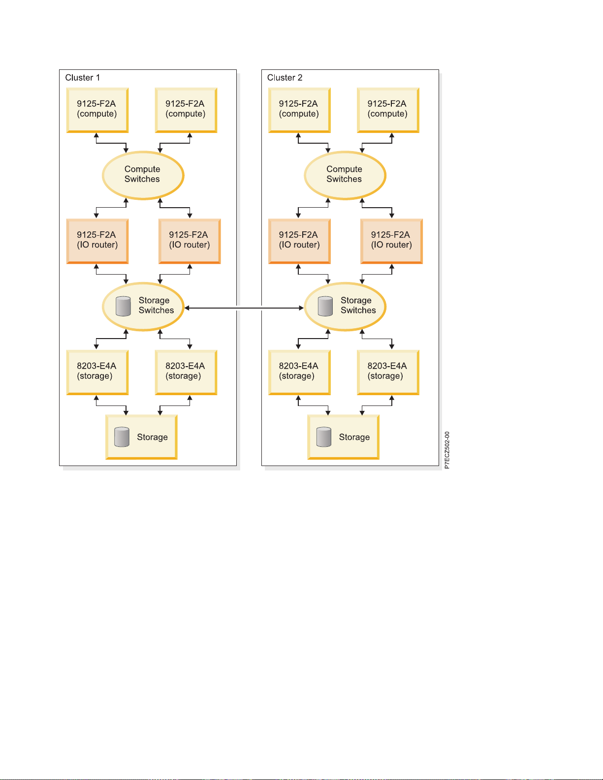
Figure 8. Example configuration with IO router servers
If you are using 12x HCAs (for example, in a 8203-E4A server), you should review “Planning 12x HCA
connections” on page 75, to understand the unique cabling and configuration requirements when using
these adapters with the available 4x switches. Also review any cabling restrictions in IBM Clusters with
the InfiniBand Switch website referenced in “Cluster information resources” on page 2.
Cable planning
While planning your cabling, keep in mind the IBM server and frame physical characteristics that affect
the planning of cable length.
In particular:
v Consider the server height and placement in the frame to plan for cable routing within the frame. This
affects the distance of the HCA connectors from the top of the raised floor.
v Consider routing to the cable entrance of a frame
v Consider cable routing within a frame, especially with respect to bend radius and cable management.
v Consider floor depth
v Remember to plan for connections from the Fabric Management Servers; see “Planning for fabric
management server” on page 64.
48 Power Systems: High performance clustering
Page 65

Record the cable connection information planned here in the “QLogic and IBM switch planning
worksheets” on page 83, for switch port connections and in a “Server planning worksheet” on page 81,
for HCA port connections.
Planning InfiniBand network cabling and configuration ends here.
Planning QLogic or IBM Machine Type InfiniBand switch configuration
You can plan for QLogic or IBM Machine Type InfiniBand switch configurations by using QLogic
planning resources including general planning guides and planning guides specific to the model being
installed.
Unless otherwise noted, this document uses the term QLogic switches interchangeably with IBM 7874
switches. Unless otherwise noted, they are functionally equivalent.
Most InfiniBand switch planning would be done using QLogic planning resources including general
planning guides and planning guides specific to the model being installed. See the reference material in
“Cluster information resources” on page 2.
Switches require some custom configuration to work well in an IBM System p high performance
computing (HPC) cluster. You must plan for the following configuration settings.
v IP-addressing on the cluster virtual local area network (VLAN) can be configured static. The address
can be planned and recorded.
v Chassis maximum transfer units (MTU) value
v Switch name
v 12x cabling considerations
v Disable telnet in favor of ssh access to the switches
v Remote logging destination (xCAT/MS is preferred)
v New chassis passwords
As part of the consideration in designing the VLAN on which the switches management ports are
populated, you can consider making that a private VLAN, or one that is protected. While the switch
chassis provides password and ssh protection, the Chassis Viewer does not use an SSL protocol.
Therefore, you can consider how this fits with the site security policies.
The IP-addressing that a QLogic switch has on the management Ethernet network is configured for static
addressing. These addresses are associated with the switch management function. The following are
important QLogic management function concepts.
v The 7874-024 (QLogic 9024) switches have a single address associated with its management Ethernet
connection.
v All other switches have one or more managed spine cards per chassis. If you want backup capability
for the management subsystem, you must have more than one managed spine in a chassis. This is not
possible for the7874-040 (QLogic9040).
v Each managed spine gets its own address so that it can be addressed directly.
v Each switch chassis also gets a management Ethernet address that is assumed by the master
management spine. This permits you to use a single address to query the chassis regardless of which
spine is the master spine. To set up management parameters (like which spine is master) each managed
spine must have a separate address.
v The 7874-240 (QLogic 9240) switch chassis is divided into two managed hemispheres. Therefore, a
master and backup managed spine within each hemisphere is required, creating a total of four
managed spines.
– Each managed spine gets its own management Ethernet address.
– The chassis has two management Ethernet addresses. One for each hemisphere.
High-performance computing clusters using InfiniBand hardware 49
Page 66

– Review the 9240 Users Guide to ensure that you understand which spine slots are used for managed
spines. Slots 1, 2, 5 and 6 are used for managed spines. The numbering of spine 1 through 3 is from
bottom to top. The numbering of spine 4 through 6 is from top to bottom.
v - The total number of management Ethernet addresses is driven by the switch model. Recall, except for
the 7874-024 (QLogic 9024), each management spine has its own IP address in addition to the chassis
address.
– 7874-024 (QLogic 9024) has one address
– 7874-240 (QLogic 9240) has from four (no redundancy) to six (full redundancy) addresses. Recall,
there are two hemispheres in this switch model, and each has its own chassis address.
– All other models have from two (no redundancy) to three addresses.
v For topology and cabling, see “Planning InfiniBand network cabling and configuration” on page 30.
Chassis MTU must be set to an appropriate value for each switch in a cluster. For more information, see
“Planning maximum transfer unit (MTU)” on page 51.
For each subnet, you must plan a different GID-prefix. For more information, see “Planning for global
identifier prefixes” on page 52.
You can assign a name to each switch, which would be used as the IB Node Description. It can be
something that indicates its physical location on a machine floor. You might want to include the frame
and slot in which it resides. The key is a consistent naming convention that is meaningful to you and
your service provider. Also, provide a common prefix to the names. This helps the tools filter on this
name in the IB Node Description. Often the customer name or the cluster name is used as the prefix. If
the servers have only one connection per InfiniBand subnet, some users find it useful to include the ibX
interface in the switch name. For example, if company XYZ has eight subnets, each with a single
connection from each server, the switches might be named XYZ ib0 through XYZ ib7 , or, perhaps, XYZ
switch 1 through XYZ switch 8.
If you have a 4x switch connecting to 12x host channel adapter (HCA), a 12x to 4x width exchanger cable
is required. For more details, see “Planning 12x HCA connections” on page 75.
If you are connecting to 9125-F2A servers, you must alter the switch port configuration to accommodate
the signal characteristics of a copper or optical cable combined with the GX++ HCA in a 9125-F2A server.
v Copper cables connected to a 9125-F2A require an amplitude setting of 0x01010101 and pre-emphasis
value of 0x01010101
v Optical cables connected to a 9125-F2A require a pre-emphasis setting of 0x0000000. The amplitude
setting is not important
v The following table shows the default values by switch model. Use this table to determine if the
default values for amplitude and pre-emphasis are sufficient.
Table 35. Switch Default Amplitude and Pre-emphasis Settings
Switch Default Amplitude Default Pre-empahsis
QLogic 9024 or IBM 7874-024 0x01010101 0x01010101
All other switch models 0x06060606 0x01010101
While passwordless ssh is preferred from xCAT/MS and the fabric management server to the switch
chassis, you can also change the switch chassis default password early in the installation process. For Fast
Fabric Toolset functionality, all the switch chassis passwords can be the same.
You can also consolidate switch chassis logs and embedded Subnet Manager logs on to a central location.
Because xCAT is also preferred as the Systems Management application, the xCAT/MS is preferred to be
50 Power Systems: High performance clustering
Page 67

the recipient of the remote logs from the switch. You can only direct logs from a switch to a single remote
host (xCAT/MS). “Set up remote logging” on page 112 provides the procedure that is used for setting up
remote logging in the cluster.
The information planned here can be recorded in a “QLogic and IBM switch planning worksheets” on
page 83.
Planning QLogic InfiniBand switch configuration ends here.
Planning maximum transfer unit (MTU):
Use this information to plan for maximum transfer units (MTU).
Based on your configuration, there are different maximum transfer units (MTUs) that can be used.
Table 36 list the MTU values that message passing interface (MPI) and Internet Protocol (IP) require for
maximum performance.
The cluster type indicates the type of cluster based on the generation and type of host channel adapters
(HCAs) that are used. You either have a homogeneous cluster based on all the HCAs being of the same
generation and type, or a heterogeneous cluster based on the HCAs being a mix of generations and types.
Cluster composition by HCA indicates the actual generation and type of HCAs being used in the cluster.
Switch and Subnet Manager (SM) settings indicate the settings for the switch chassis and Subnet
Manager. The chassis MTU is used by the switch chassis and applies to the entire chassis, and can be set
the same for all chassis in the cluster. Furthermore, chassis MTU affects the MPI. The broadcast MTU is
set by the Subnet Manager and affects IP. It is part of the broadcast group settings. It can be the same for
all broadcast groups.
The MPI MTU indicates the setting that the MPI requires for the configuration. The IP MTU indicates the
setting that the IP requires. The MPI MTU and IP MTU are included to help understand the settings
indicated in the Switch and SM Settings column. The BC rate is the broadcast MTU rate setting, which
can either be 10 GB (3) or 20 GB (6). The SDR switches run at 10 GB and DDR switches run at 20 GB.
The number in parentheses in the following table indicates the parameter setting in the firmware and SM
which represents that setting.
Table 36. MTU settings
MPI
Cluster type Cluster composition by HCA Switch and SM settings
®
Homogeneous
HCAs
Homogeneous
HCAs
Homogeneous
HCAs
System p5
System p (POWER6)GX++ DDR
HCA 9125-F2A, 8204-E8A or
8203-E4A
POWER6 GX+ SDR HCA
8204-E8A or 8203-E4A
GX+ SDR HCA only Chassis MTU=2K(4)
Broadcast MTU=2K(5)
BC rate = 10 GB (3)
Chassis MTU=4K(5)
Broadcast MTU=4K(5)
BC rate = 10 GB (3) for SDR switches,
or 20 GB (6) for DDR switches
Chassis MTU=2K(4)
Broadcast MTU=2K(4)
MTU IP MTU
2K 2K
4K 4K
2K 2K
BC rate = 10 GB (3) for SDR switches,
or 20 GB (6) for DDR switches
High-performance computing clusters using InfiniBand hardware 51
Page 68

Table 36. MTU settings (continued)
MPI
Cluster type Cluster composition by HCA Switch and SM settings
12
Homogeneous
HCAs
Heterogeneous
HCAs
Heterogeneous
HCAs
Heterogeneous
HCAs
1
IPoIB performance between compute nodes might be degraded because they are bound by the 2 KB MTU.
ConnectX HCA
blades)
GX++ DDR HCA in 9125-F2A
(compute servers) and GX+ SDR
HCA in 8204-E8A or 8203-E4A
(storage servers)
POWER6 GX++ DDR HCA
(compute) and p5 SDR HCA
(storage servers)
ConnectX HCA (compute) and p5
HCA (storage servers)
only (System p
Chassis MTU=2K(4)
Broadcast MTU=2K(4)
BC rate = 10 GB (3) for SDR switches,
or 20 GB (6) for DDR switches
Chassis MTU=4K(5)
Broadcast MTU=2K(4)
BC rate = 10 GB (3)
Chassis MTU=4K(5)
Broadcast MTU=2K(4)
BC rate = 10 GB (3)
Chassis MTU=2K(4)
Broadcast MTU=2K(4)
BC rate = 10 GB (3)
MTU IP MTU
2K 2K
Between
compute
13
=
only
4KB
Between
POWER6
only = 4
KB
2K 2K
2K
2K
12
While Connect X HCAs are used in the Fabric management servers, they are not part of the IPoIB
configuration, nor the MPI configuration. Therefore, their potential MTU is not relevant.
13
IPoIB performance between compute nodes might be degraded because they are bound by the 2 K
MTU.
Note: For IFS 5, record 2048 for 2 K MTU, and record 4096 for 4 K MTU. For the rates in IFS 5, record 20
g for 20 GB, and record 10 g for 10 GB.
The configuration settings for fabric managers can be recorded in the “QLogic fabric management
worksheets” on page 92.
The configuration settings for switches can be recorded in the “QLogic and IBM switch planning
worksheets” on page 83.
Planning MTU ends here.
Planning for global identifier prefixes:
This information describes why and how to plan for fabric global identifier (GID) prefixes in an IBM
System p high-performance computing (HPC) cluster.
Each subnet in the InfiniBand network must be assigned a GID prefix, which is used to identify the
subnet for addressing purposes. The GID prefix is an arbitrary assignment with a format of:
xx:xx:xx:xx:xx:xx:xx:xx (for example: FE:80:00:00:00:00:00:01). The default GID prefix is
FE:80:00:00:00:00:00:00.
The GID prefix is set by the Subnet Manager. Therefore, each instance of the Subnet Manager must be
configured with the appropriate GID prefix. On any given subnet, all instances of the Subnet Manager
(master and backups) must be configured with the same GID prefix.
52 Power Systems: High performance clustering
Page 69

Typically, all but the lowest order byte of the GID-prefix is kept constant, and the lowest byte is the
number for the subnet. The numbering scheme typically begins with 0 or 1.
The configuration settings for fabric managers can be recorded in the “QLogic fabric management
worksheets” on page 92.
Planning GID Prefixes ends here.
Planning an IBM GX HCA configuration
An IBM GX host channel adapter (HCA) must have certain configuration settings to work in an IBM
POWER®InfiniBand cluster.
The following configuration settings are required to work with an IBM POWER InfiniBand cluster:
v Globally-unique identifier (GUID) index
v Capability
v Global identifier (GID) prefix for each port of an HCA
InfiniBand subnet IP addressing is based on subnet restrictions. For more information, see “IP subnet
addressing restriction with RSCT.” Each physical InfiniBand HCA contains a set of 16 GUIDs that can be
assigned to logical partition profiles. These GUIDs are used to address logical HCA (LHCA) resources on
an HCA. You can assign multiple GUIDs to each profile, but you can assign only one GUID from each
HCA to each partition profile. Each GUID can be used by only one logical partition at a time. You can
create multiple logical partition profiles with the same GUID, but only one of those logical partition
profiles can be activated at a time.
The GUID index is used to choose one of the 16 GUIDs available for an HCA. It can be any number from
1 through 16. Often, you can assign a GUID index based on which logical partition (LPAR) and profile
you are configuring. For example, on each server you might have four logical partitions. The first logical
partition on each server might use a GUID index of 1. The second would use a GUID index of 2. The
third would use a GUID index of 3, and the fourth using a GUID index of 4.
The Capability setting is used to indicate the level of sharing that can be done. The levels of sharing are
as follows.
1. Low
2. Medium
3. High
4. Dedicated
While the GID-prefix for a port is not something that you explicitly set, it is important to understand the
subnet to which a port attaches. This GID-prefix is determined by the switch to which the HCA port is
connected. The GID-prefix is configured for the switch. For more information, see “Planning for global
identifier prefixes” on page 52.
For more information about partition profiles, see Partition profile.
The planned configuration settings can be recorded in a “Server planning worksheet” on page 81 which
is used to record HCA configuration information.
Note: The 9125-F2A servers with “heavy” I/O system boards might have an extra InfiniBand device
defined. The defined device is always iba3. Delete iba3 from the configuration.
Planning an IBM GX HCA configuration ends here.
IP subnet addressing restriction with RSCT:
High-performance computing clusters using InfiniBand hardware 53
Page 70

When using RSCT, there are restrictions to how you can configure Internet Protocol (IP) subnet
addressing in a server attached to an InfiniBand network.
Note: RSCT is no longer required for IBM Power HPC Clusters. This topic is for clusters that still rely on
RSCT for InfiniBand network status monitoring.
Both IP and InfiniBand use the term subnet. These are two distinctly different entities as described in the
following paragraphs.
The IP addresses for the host channel adapter (HCA) network interfaces must be set up. So that no two
IP addresses in a given LPARs are in the same IP subnet. When planning for the IP subnets in the cluster,
as many separate IP subnets can be established as there are IP addresses on a given LPAR.
The subnets can be set up so that all IP addresses in a given IP subnet are connected to the same
InfiniBand subnet. If there are n network interfaces on each logical partition connected to the same
InfiniBand subnet, then n separate IP subnets can be established.
Note: This IP subnetting limitation does not prevent multiple adapters or ports from being connected to
the same InfiniBand subnet. It is only an indication of how the IP addresses must be configured.
Management subsystem planning
This information is a summary of the planning required for the components of the management
subsystem.
This information is a summary of the service and cluster VLANs, Hardware Management Console
(HMC), Systems Management application and Server, vendor Fabric Management applications, AIX NIM
server and Linux Distribution server. And pointers to key references in planning the management
subsystem. Also, you must plan for the frames that house the management consoles.
Customer-supplied Ethernet service and cluster VLANs are required to support the InfiniBand cluster
computing environment. The number of Ethernet connections depends on the number of servers, bulk
power controllers (BPCs) in 24 - inch frames, InfiniBand switches, and HMCs in the cluster. The Systems
Management application and server, which might include Cluster Ready Hardware Server (CRHS)
software would also require a connection to the service VLAN.
Note: While you can have two service VLANs on different subnets to support redundancy in IBM
servers, BPCs, and HMCs, the InfiniBand switches support only a single service VLAN. Even though
some InfiniBand switch models have multiple Ethernet connections, these connections connect to different
management processors and therefore can connect to the same Ethernet network.
An HMC might be required to manage the LPARs and to configure the GX bus host channel adapters
(HCAs) in the servers. The maximum number of servers that can be managed by an HMC is 32. When
there are more than 32 servers, additional HMCs are required. For details, see Solutions with the Hardware
Management Console in the IBM systems Hardware Information Center. It is under the Planning >
Solutions > Planning for consoles, interfaces, and terminals path.
If you have a single HMC in the cluster, it is normally configured to be the required dynamic host
configuration protocol (DHCP) server for the service VLAN. And the xCAT/MS is the DHCP server for
the cluster VLAN. If multiple HMCs are used, then typically the xCAT M/S would be the DHCP server
for both the cluster and service VLANs.
The servers have connections to the service and cluster VLANs. See xCAT documentation for more
information about the cluster VLAN. See the server documentation for more information about
connecting to the service VLAN. In particular, consider the following items.
v The number of service processor connections from the server to the service VLAN
54 Power Systems: High performance clustering
Page 71

v If there is a BPC for the power distribution, as in a 24 - inch frame, it might provide a hub for the
processors in the frame, permitting for a single connection per frame to the service VLAN.
After you know the number of devices and cabling of your service and cluster VLANs, you must
consider the device IP-addressing. The following items are the key considerations for IP addressing.
1. Determine the domain addressing and netmasks for the Ethernet networks that you implement.
2. Assign static-IP-addresses
a. Assign a static IP address for HMCs when you are using xCAT. This static IP address is
mandatory when you have multiple HMCs in the cluster.
b. Assign a static IP address for switches when you are using xCAT. This static IP address is
mandatory when you have multiple HMCs in the cluster.
3. Determine the DHCP range for each Ethernet subnet.
4. If you are using xCAT and multiple HMC, the DHCP server is preferred to be on the xCAT
management server, and all HMCs must have their DHCP server capability disabled. Otherwise, you
are in a single HMC environment where the HMC is the DHCP server for the service VLAN.
If there are servers in the cluster without removable media (CD or DVD), you would require an AIX NIM
server for System p server diagnostics. If you are using AIX in your partitions, this provides NIM service
for the partition. The NIM server would be on the cluster VLAN.
If there are servers running the Linux operating system on your logical partitions that do not have
removable media (CD or DVD), a distribution server is required. The “Cluster summary worksheet” on
page 77 can be used to record the information for your management subsystem planning.
Frames or racks must be planned for the management servers. You can consolidate the management
servers into the same rack whenever possible. The following management servers can be considered.
v HMC
v xCAT management server
v Fabric management server
v AIX NIM and Linux distribution servers
v Network time protocol (NTP) server
Further management subsystem considerations are:
v Review “Installing and configuring the management subsystem” on page 98 for the management
subsystem installation tasks. The information helps you to assign tasks in the “Installation coordination
worksheet” on page 73.
v “Planning your Systems Management application”
v “Planning for QLogic fabric management applications” on page 56
v “Planning for fabric management server” on page 64
v “Planning event monitoring with QLogic and management server” on page 66
v “Planning to run remote commands with QLogic from the management server” on page 67
Planning your Systems Management application
You must choose either xCAT as your Systems Management application.
If you are installing servers with Red Hat partitions, then you must use xCAT as your Systems
Management application.
Planning xCAT as your Systems Management application: For general xCAT planning information see
xCAT documentation referenced in Table 4 of “Cluster information resources” on page 2. This section
concerns itself more with how xCAT fits into a cluster with InfiniBand.
High-performance computing clusters using InfiniBand hardware 55
Page 72

If you have along multiple HMCs and are using xCAT, the xCAT Management Server (xCAT/MS) is
typically the DHCP server for the service VLAN. If the cluster VLAN is public or local site network, then
it is possible that another server might be set up as the DHCP server. It is preferred that the xCAT
Management Server to be a stand-alone server. If you use one of the compute, storage or IO router
servers in the cluster for xCAT, the xCAT operation might degrade performance for user applications, and
it would complicate the installation process with respect to server setup and discovery on the service
VLAN.
You can also set up xCAT event management to be used in a cluster. To set up xCAT event management,
you must plan for the following items.
v The type of syslogd that you are going to use. At the least, you must understand the default syslogd
that comes with the operating system on which xCAT would run. The two main varieties are syslog
and syslog-ng. In general syslog is used in AIX and RedHat. If you prefer syslog-ng, which has more
configuration capabilities than syslog, you might also obtain and install syslog-ng on AIX and RedHat.
v Whether you want to use tcp or udp as the protocol for transferring syslog entries from the fabric
management server to the xCAT/MS. You must use udp if the xCAT/MS is using syslog. If the
xCAT/MS has syslog-ng installed, you can use tcp for better reliability. The switches only use udp.
v If syslog-ng is used on the xCAT/MS, there is a src line that controls the IP addresses and ports over
which syslog-ng accepts logs. The default setup is address 0.0.0.0, which means all addresses. For
added security, you might want to plan to have a src definition for each switch IP address and each
fabric management server IP address rather than opening all IP addresses on the service VLAN. For
information about the format of the src line see “Set up remote logging” on page 112.
Running the remote command from the xCAT/MS to the Fabric Management Servers is advantageous
when you have more than one Fabric Management Server in a cluster. To start the remote command to
the Fabric Management Servers, you must research how to exchange ssh keys between the fabric
management server and the xCAT/MS. This is standard open SSH protocol setup as done in either the
AIX operating system or the Linux operating system. For more information see, “Planning to run remote
commands with QLogic from the management server” on page 67
If you do not require a xCAT Management Server, you might need a server to act as a Network
Installation Manager (NIM) server for diagnostics. This is the case for servers that do not have removable
media (CD or DVD), such as a 575 (9118-575).
If you have servers with no removable media that are running Linux logical partitions, you might require
a server to act as a distribution server.
If you require both an AIX NIM server and a Linux distribution server, and you choose the same server
for both, a reboot is required to change between the services. If the AIX NIM server is used only for
eServer diagnostics, this might be acceptable in your environment. However, you must understand that
this may prolong a service call if use of the AIX NIM service is required. For example, the server that
might normally act as a Linux distribution server could have a second boot image to server as the AIX
NIM server. If AIX NIM services are required for System p diagnostics during a service call, the Linux
distribution server must be rebooted to the AIX NIM image before diagnostics can be performed.
The configuration settings planned here can be recorded in the “xCAT planning worksheets” on page 89.
Planning xCAT as your Systems Management application ends here
Planning for QLogic fabric management applications
Use this information to plan for the QLogic Fabric Management applications.
Planning the fabric manager and fabric Viewer:
This information is used to plan for the Fabric Manager and the Fabric Viewer.
56 Power Systems: High performance clustering
Page 73

Most details are available in the Fabric Manager and Fabric Viewer Users Guide from QLogic. This
information highlights information from a cluster perspective.
The Fabric Viewer is intended to be used as documented by QLogic. However, it is not scalable and thus
would be only used in small clusters when necessary.
The Fabric Manager has a few key parameters that can be set up in a specific manner for IBM System p
HPC clusters.
The following items are the key planning points to for your Fabric Manager in an IBM System p HPC
cluster.
Note: See Figure 9 on page 58 and Figure 10 on page 58 for illustrations of typical fabric management
configurations.
v For HPC clusters, IBM has only qualified use of a host-based Fabric Manager (HFM). The HFM is
typically referred as host-based Subnet Manager (HSM), because the Subnet Manager is considered the
most important component of the Fabric Manager.
v The host for HSM is the fabric management server. For more information, see “Planning for fabric
management server” on page 64.
– The host requires one host channel adapter (HCA) port per subnet to be managed by the Subnet
Manager.
– If you have more than four subnets in your cluster, you must have two hosts actively servicing your
fabrics. To permit for backups, up to four hosts to be fabric management servers are required. That
is two hosts as primaries and two hosts as backups.
– Consolidating switch chassis and Subnet Manager logs on to a central location is preferred. Since
xCAT can be used as the Systems Management application, the xCAT/MS can be the recipient of the
remote logs from the switch. You can direct logs from a fabric management server to multiple
remote hosts. See “Set up remote logging” on page 112 for the procedure that is used to set up
remote logging in the cluster.
– IBM has qualified the System x 3550 or 3650 for use as a Fabric Management Server.
– IBM has qualified the QLogic HCAs for use in the Fabric Management Server.
v Backup fabric management servers are preferred to maintain availability of the critical HSM function.
v At least one unique instance of Fabric Manager to manage each subnet is required.
– A host-based Fabric Manager instance is associated with a specific HCA and port over which it
communicates with the subnet that it manages. For example, if you have four subnets and one
fabric management server, it has four instances of Subnet Manager running on it; one for each
subnet. Also, the server must be attached to all four subnets.
– The Fabric Manager consists of four processes: the subnet manager (SM), the performance manager
(PM), baseboard manager (BM) and fabric executive (FE). For more details, see “Fabric manager” on
page 17 and the QLogic Fabric Manager Users Guide.
– When more than one HSM is configured to manage a fabric, the priority (SM_x_priority) is used to
determine which one manages the subnet at a given time. The wanted master, or primary, can be
configured with the highest priority. The priorities are 0- through 15, with 15 being the highest.
– In addition to the priority parameter, there is an elevated priority parameter
(SM_x_elevated_priority) that is used by the backup when it takes over for the master. More details
are available in the following explanation of key parameters.
– It is common practice in the industry for the terms Subnet Manager and Fabric Manager to be used
interchangeably, because the Subnet Manager performs the most vital role in managing the fabric.
v The HSM license fee is based on the size of the cluster that it covers. See the vendor documentation
and website referenced in “Cluster information resources” on page 2.
v The following items are embedded Subnet Manager (ESM) considerations.
– IBM is not qualifying the embedded Subnet Manager.
High-performance computing clusters using InfiniBand hardware 57
Page 74

– If you use an embedded Subnet Manager, you might experience performance problems and outages
if the subnet has more than 64 IBM GX+ or GX++ HCA ports attached to it. This is because of the
limited compute power and memory available to run the embedded Subnet Manager in the switch.
And because the IBM GX+ or GX++ HCAs also present themselves as multiple logical devices,
because they can be virtualized. For more information, see “IBM GX+ or GX++ host channel
adapter” on page 7. Considering these restrictions, you might want to restrict embedded Subnet
Manager use to subnets with only one model 9024 switch in them.
– If you plan to use the embedded Subnet Manager, you need the fabric management server for the
Fast Fabric Toolset. For more information, see “Planning Fast Fabric Toolset” on page 63. If you use
ESM, it does not eliminate the need for a fabric management server. The need for a backup fabric
management server is not as great, but it is still preferred.
– You might find it simpler to maintain host-based Subnet Manager code than embedded Subnet
Manager code.
– You must obtain a license for the embedded Subnet Manager, since it is keyed to the switch chassis
serial number.
Figure 9. Typical Fabric Manager configuration on a single fabric management server
Figure 10. Typical fabric management server configuration with eight subnets
The key parameters for which to plan for the Fabric Manager are:
Note: If a parameter applies to only a certain component of the fabric manager that are noted as in the
following section. Otherwise, you must specify that parameter for each component of each instance of the
fabric manager on the Fabric Management Server. Components of the fabric manager are: subnet manager
(SM), performance manager (PM), baseboard manager (BM), and fabric executive (FE).
v Plan a global identifier (GID) prefix for each subnet. Each subnet requires a different GID prefix, which
is set by the Subnet Manager. The default is 0xfe80000000000000. This GID prefix is for the subnet
manager only.
v LMC=2topermit for 4 LIDs. This is important for IBM MPI performance. This is for the subnet
manager only. It is important to note that the IBM MPI performance gain is realized in the FIFO mode.
Consult performance papers and IBM for information about the impact of LMC=2onRDMA. The
default is to not use the LMC = 2, and use only the first of the 4 available LIDs. This reduces startup
time and processor usage for managing Queue Pairs (QPs), which are used in establishing
protocol-level communication between InfiniBand interfaces. For each LID used, another QP must be
created to communicate with another InfiniBand interface on the InfiniBand subnet. For more
information and an example failover and recovery scenario, see “QLogic subnet manager” on page 153
v For each Fabric Management Server, plan which instance of the fabric manager can be used to manage
each subnet. Instances are numbered from 0 to 3 on a single Fabric Management Server. For example, if
a single Fabric Management server is managing four subnets, you would typically have instance 0
manage the first subnet. Instance 1 manage the second subnet, instance 2 manage the third subnet and
instance 3 manage the fourth subnet. All components under a particular fabric manager instance are
referenced using the same instance. For example, fabric manager instance 0, would have SM_0, PM_0,
BM_0, and FE_0.
v For each Fabric Management Server, plan which HCA and HCA port on each would connect which
subnet. You need this to point each fabric management instance to the correct HCA and HCA port so
that it manages the correct subnet. This is specified individually for each component. However, it can
be the same for each component in each instance of fabric manager. Otherwise, you would have the
SM component of the fabric manager 0 manage one subnet and the PM component of the fabric
manager 0 managing another subnet. This would make it confusing to try to understand how things
are set up. Typically, instance 0 manages the first subnet, which typically is on the first port of the first
58 Power Systems: High performance clustering
Page 75

HCA. And instance 1 manages the second subnet, which typically is on the second port of the first
HCA. Instance 2 manages the third subnet, which typically is on the first port of the second HCA, and
instance 3 manages the fourth subnet, which typically is on the second port of the second HCA.
v Plan for a backup Fabric Manager for each subnet.
v Plan for the maximum transfer unit (MTU) by using the rules found in “Planning maximum transfer
unit (MTU)” on page 51. This MTU is for the subnet manager only.
v In order to account for maximum pHyp response times, change the default MaxAttempts value from 3
to 8. This controls the number of times that the SM attempts before deciding that it cannot reach a
device.
v Do not start the Baseboard Manager (BM), Performance Manager (PM), or Fabric Executive (FE), unless
you require the Fabric Viewer. Which would not be necessary if you are running the Host-based fabric
manager and FastFabric Toolset.
v There are other parameters that can be configured for the Subnet Manager. However, the defaults are
typically chosen for Subnet Manager. Further details can be found in the QLogic Fabric Manager Users
Guide.
Examples of configuration files for IFS 5:
Example setup of host-based fabric manager for IFS 5
The following is a set of example entries from an qlogic_fm.xml file on a fabric management server,
which manages two subnets, where the fabric manager is the primary one, as indicated by a priority=1.
These entries are found throughout the file in the startup section, and each of the manager sections in
each of the instance sections. In this case, instance 0 manages subnet 1 and instance 1 manages subnet 2
and instance 2 manages subnet 3 and instance 3 manages subnet 4.
Note: Comments made in boxes in this example are not found in the example file. They are here to help
clarify where in the file you would find these entries, or give more information. Also, the example file
has many more comments that are not given in this example. You might find these comments to be
helpful in understanding the attributes and the file format in more detail, but they would make this
example difficult to read. Finally, in order to conserve space, most of the attributes that typically remain
at default are not included.
<?xml version="1.0" encoding="utf-8"?>
<Config>
<!-- Common FM configuration, applies to all FM instances/subnets -->
<Common>
THE APPLICATIONS CONTROLS ARE NOT USED
<!-- Various sets of Applications which may be used in Virtual Fabrics -->
<!-- Applications defined here are available for use in all FM instances. -->
...
<!-- All Applications, can be used when per Application VFs not needed -->
...
<!-- Shared Common config, applies to all components: SM, PM, BM and FE -->
<!-- The parameters below can also be set per component if needed -->
<Shared>
...
Priorities are typically set within the FM instances farther below
<Priority>0</Priority> <!-- 0 to 15, higher wins -->
<ElevatedPriority>0</ElevatedPriority> <!-- 0 to 15, higher wins -->
...
</Shared>
<!-- Common SM (Subnet Manager) attributes -->
High-performance computing clusters using InfiniBand hardware 59
Page 76

<Sm>
<Start>1</Start> <!-- default SM startup for all instances -->
...
<!-- **************** Fabric Routing **************************** -->
...
<Lmc>2</Lmc> <!-- assign 2^lmc LIDs to all CAs (Lmc can be 0-7) -->
...
<!-- **************** IB Multicast **************************** -->
<Multicast>
...
<!-- *************************************************************** -->
<!-- Pre-Created Multicast Groups -->
...
<MulticastGroup>
<Create>1</Create>
<MTU>4096</MTU>
<Rate>20g</Rate>
<!-- <SL>0</SL> -->
<QKey>0x0</QKey>
<FlowLabel>0x0</FlowLabel>
<TClass>0x0</TClass>
</MulticastGroup>
...
</Multicast>
...
<!-- **************** Fabric Sweep **************************** -->
...
<MaxAttempts>8</MaxAttempts>
...
<!-- **************** SM Logging/Debug **************************** -->
...
<NodeAppearanceMsgThreshold>10</NodeAppearanceMsgThreshold>
...
<!-- **************** Miscellaneous **************************** -->
...
<!-- Overrides of the Common.Shared parameters if desired -->
<Priority>1</Priority> <!-- 0 to 15, higher wins -->
<ElevatedPriority>12</ElevatedPriority> <!-- 0 to 15, higher wins -->
...
</Sm>
<!-- Common FE (Fabric Executive) attributes -->
<Fe>
<Start>0</Start> <!-- default FE startup for all instances -->
...
60 Power Systems: High performance clustering
Page 77

</Fe>
<!-- Common PM (Performance Manager) attributes -->
<Pm>
<Start>0</Start> <!-- default PM startup for all instances -->
...
</Pm>
<!-- Common BM (Baseboard Manager) attributes -->
<Bm>
<Start>0</Start> <!-- default BM startup for all instances -->
...
</Bm>
</Common>
Instance 0 of the FM. When editing the configuration file,
it is recommended that you note the instance in a comment
<!-- A single FM Instance/subnet -->
<!—INSTANCE 0 -->
<Fm>
...
<Shared>
...
<Name>ib0</Name> <!-- also for logging with _sm, _fe, _pm, _bm appended -->
<Hca>1</Hca> <!-- local HCA to use for FM instance, 1=1st HCA -->
<Port>1</Port> <!-- local HCA port to use for FM instance, 1=1st Port -->
<PortGUID>0x0000000000000000</PortGUID> <!-- local port to use for FM -->
<SubnetPrefix>0xfe80000000000042</SubnetPrefix> <!-- should be unique -->
...
</Shared>
<!-- Instance Specific SM (Subnet Manager) attributes -->
<Sm>
<!-- Overrides of the Common.Shared, Common.Sm or Fm.Shared parameters -->
<Priority>1</Priority>
<ElevatedPriority>8</ElevatedPriority>
</Sm>
...
</Fm>
Instance 1 of the FM. When editing the configuration file,
it is recommended that you note the instance in a comment
<!-- A single FM Instance/subnet -->
<!—INSTANCE 1 -->
<Fm>
...
<Shared>
<Start>1</Start> <!-- Overall Instance Startup, see fm0 for more info -->
<Name>ib1</Name> <!-- also for logging with _sm, _fe, _pm, _bm appended -->
<Hca>1</Hca> <!-- local HCA to use for FM instance, 1=1st HCA -->
<Port>2</Port> <!-- local HCA port to use for FM instance, 1=1st Port -->
<PortGUID>0x0000000000000000</PortGUID> <!-- local port to use for FM -->
<SubnetPrefix>0xfe80000000000043</SubnetPrefix> <!-- should be unique -->
<!-- Overrides of the Common.Shared or Fm.Shared parameters if desired -->
<!-- <LogFile>/var/log/fm1_log</LogFile> --> <!-- log for this instance -->
</Shared>
<!-- Instance Specific SM (Subnet Manager) attributes -->
<Sm>
<!-- Overrides of the Common.Shared, Common.Sm or Fm.Shared parameters -->
<Start>1</Start>
<Lmc>2</Lmc>
High-performance computing clusters using InfiniBand hardware 61
Page 78

...
<Priority>0</Priority> <!-- 0 to 15, higher wins -->
<ElevatedPriority>8</ElevatedPriority> <!-- 0 to 15, higher wins -->
</Sm>
...
</Fm>
Instance 2 of the FM. When editing the configuration file,
it is recommended that you note the instance in a comment
<!-- A single FM Instance/subnet -->
<!—INSTANCE 2 -->
<Fm>
...
<Shared>
<Start>1</Start> <!-- Overall Instance Startup, see fm0 for more info -->
<Name>ib2</Name> <!-- also for logging with _sm, _fe, _pm, _bm appended -->
<Hca>2</Hca> <!-- local HCA to use for FM instance, 1=1st HCA -->
<Port>1</Port> <!-- local HCA port to use for FM instance, 1=1st Port -->
<PortGUID>0x0000000000000000</PortGUID> <!-- local port to use for FM -->
<SubnetPrefix>0xfe80000000000031</SubnetPrefix> <!-- should be unique -->
<!-- Overrides of the Common.Shared or Fm.Shared parameters if desired -->
<!-- <LogFile>/var/log/fm2_log</LogFile> --> <!-- log for this instance -->
</Shared>
<!-- Instance Specific SM (Subnet Manager) attributes -->
<Sm>
...
<Priority>1</Priority> <!-- 0 to 15, higher wins -->
<ElevatedPriority>8</ElevatedPriority> <!-- 0 to 15, higher wins -->
</Sm>
...
</Fm>
Instance 3 of the FM. When editing the configuration file,
it is recommended that you note the instance in a comment
<!-- A single FM Instance/subnet -->
<!—INSTANCE 3 -->
<Fm>
...
<Shared>
<Start>1</Start> <!-- Overall Instance Startup, see fm0 for more info -->
<Name>ib3</Name> <!-- also for logging with _sm, _fe, _pm, _bm appended -->
<Hca>2</Hca> <!-- local HCA to use for FM instance, 1=1st HCA -->
<Port>2</Port> <!-- local HCA port to use for FM instance, 1=1st Port -->
<PortGUID>0x0000000000000000</PortGUID> <!-- local port to use for FM -->
<SubnetPrefix>0xfe80000000000015</SubnetPrefix> <!-- should be unique -->
<!-- Overrides of the Common.Shared or Fm.Shared parameters if desired -->
<!-- <LogFile>/var/log/fm3_log</LogFile> --> <!-- log for this instance -->
</Shared>
<!-- Instance Specific SM (Subnet Manager) attributes -->
<Sm>
...
<Priority>0</Priority> <!-- 0 to 15, higher wins -->
<ElevatedPriority>8</ElevatedPriority> <!-- 0 to 15, higher wins -->
</Sm>
62 Power Systems: High performance clustering
Page 79

...
</Fm>
</Config>
Plan for remote logging of Fabric Manager events:
v Plan to update /etc/syslog.conf (or the equivalent syslogd configuration file on your Fabric
Management Server) to point syslog entries to the Systems Management server. This requires
knowledge of the Systems Management Servers IP address. It is best to limit these syslog entries to
those that are created by the Subnet Manager. However, some syslogd applications generally do not
permit finely tuned forwarding.
– For the embedded Subnet Manager, the forwarding of log entries is achieved through a command
on the switch command-line interface (CLI), or through the Chassis Viewer.
v You are required to set a Notice message threshold for each Subnet Manager instance. This message is
used to limit the number of Notice or higher messages logged by the Subnet Manager on sweeps of
the network. The suggested limit is 10. Generally, if the number of Notice messages is greater than 10,
then the user is probably rebooting nodes or powering on switches again and causing links to go
down. See the IBM Clusters with the InfiniBand Switch website referenced in “Cluster information
resources” on page 2, for any updates to this suggestion.
The configuration setting planned here can be recorded in “QLogic fabric management worksheets” on
page 92.
Planning for Fabric Management and Fabric Viewer ends here
Planning Fast Fabric Toolset:
The Fast Fabric Toolset provides reporting and health check tools that are important for managing and
monitoring the fabric.
In-depth information about the Fast Fabric Toolset can be found in the Fast Fabric Toolset Users Guide
available from QLogic. The following information provides details about the Fast Fabric Toolset from a
cluster perspective.
The following items are the key things to remember when setting up the Fast Fabric Toolset in an IBM
System p or IBM Power Systems HPC cluster.
v The Fast Fabric Toolset requires you to install the QLogic InfiniServ host stack, which is part of the
Fast Fabric Toolset bundle.
v The Fast Fabric Toolset must be installed on each Fabric Management Server, including backups. See
“Planning for fabric management server” on page 64.
v The Fast Fabric tools that rely on the InfiniBand interfaces to collect report data can work only with
subnets to which their server is attached. Therefore, if you require more than one primary Fabric
Management Server, because you have more than four subnets. Then you must run two different
instances of the Fast Fabric Toolset on two different servers to query the state of all subnets.
v The Fast Fabric Toolset is used to interface with the following hardware:
– Switches
– Fabric management server hosts
– Not IBM systems (Vendor systems)
v To use xCAT for remote command access to the Fast Fabric Toolset, you must set up the host running
Fast Fabric as a device managed by xCAT. You can exchange ssh-keys with it for passwordless access.
v The master node referred in the Fast Fabric Toolset Users Guide is considered to be the host running the
Fast Fabric Toolset. In IBM System p or IBM Power Systems HPC clusters, this is not a compute or I/O
node, but is generally the Fabric Management Server.
High-performance computing clusters using InfiniBand hardware 63
Page 80

v You cannot use the message passing interface (MPI) performance tests because they are not compiled
for the IBM System p or IBM Power Systems HPC clusters host stack.
v High-Performance Linpack (HPL) in the Fast Fabric Toolset is not applicable to IBM clusters.
v The Fast Fabric Toolset configuration must be set up in its configuration files. The default configuration
files are documented in the Fast Fabric Toolset. The following list indicates key parameters to be
configured in Fast Fabric Toolset configuration files.
– Switch addresses go into chassis files.
– Fabric management server addresses go into host files.
– The IBM system addresses do not go into host files.
– Create groups of switches by creating a different chassis file for each group. Some suggestions are:
1. A group of all switches, because they are all accessible on the service virtual local area network
(VLAN)
2. Groups that contain switches for each subnet
3. A group that contains all switches with ESM (if applicable)
4. A group that contains all switches running primary ESM (if applicable)
5. Groups for each subnet which contain the switches running ESM in the subnet (if applicable) -
include primaries and backups
– Create groups of Fabric Management Servers by creating a different host file for each group. Some
suggestions are:
1. A group of all fabric management servers, because they are all accessible on the service VLAN
2. A group of all primary fabric management servers
3. A group of all backup fabric management servers
v Plan an interval at which to run Fast Fabric Toolset health checks. Because health checks use fabric
resources, you cannot run them frequently enough to cause performance problems. Use the
recommendation given in the Fast Fabric Toolset Users Guide. Generally, you cannot run health checks
more often than every 10 minutes. For more information, see “Health checking” on page 157.
v In addition to running the Fast Fabric Toolset health checks, it is suggested that you query error
counters using iba_reports –o errors –F “nodepat:[switch IB node description pattern” –c
[config file] at least once every hour. Run this checks with a configuration file that has thresholds
turned to 1 for all but the V15Dropped and PortRcvSwitchRelayErrors, which can be commented out
or set to 0. For more information, see “Health checking” on page 157.
v You must configure the Fast Fabric Toolset health checks to use either the hostsm_analysis tools for
host-based fabric management or esm_analysis tools for embedded fabric management.
v If you are using host-based fabric management, you are required to configure Fast Fabric Toolset to
access all of the Fabric Management Servers running Fast Fabric.
v If you do not choose to set up passwordless ssh between the Fabric Management Server and the
switches, you must set up the fastfabric.conf file with the switch chassis passwords.
v The configuration setting planned here can be recorded in “QLogic fabric management worksheets” on
page 92.
Planning for Fast Fabric Toolset ends here.
Planning for fabric management server
With QLogic switches, the fabric management server is required to run the Fast Fabric Toolset, which is
used for managing and monitoring the InfiniBand network.
With QLogic switches, unless you have a small cluster, it is preferred that you use the host-based Fabric
Manager, which would also run on the Fabric Management Server. The total package of Fabric Manager
and Fast Fabric Toolset is known as the InfiniBand Fabric Suite (IFS). The fabric management server has
the following requirements.
v IBM System x 3550 or 3650.
64 Power Systems: High performance clustering
Page 81

– The 3550 is 1U high and supports two PCI Express (PCIe) slots. It can support a total of four
subnets.
–
v Memory requirements
– In the following bullets, a node is either a GX HCA port with a single logical partition, or a
PCI-based HCA port. If you have implemented more than one active logical partition in a server,
count each additional logical partition as an additional node. This also assumes a typical fat-tree
topology with either a single switch chassis per plane, or a combination of edge switches and core
switches. Management of other topologies might consume more memory.
– For fewer than 500 nodes, you require 500 MB for each instance of fabric manager running on a
fabric management server. For example, with four subnets being managed by a server, you would
require 2 GB of memory.
– For 500 to 1500 nodes, you require 1 GB for each instance of fabric manager running on a fabric
management server. For example, with four subnets being managed by a server, you would require
4 GB of memory.
– Swap space must follow Linux guidelines. This requires at least twice as much swap space as
physical memory.
v Plan sufficient rack space for the fabric management server. If space is available, the fabric
management server can be placed in the same rack with other management consoles such as the
Hardware Management Console (HMC), xCAT/MS, and others.
v One QLogic host channel adapter (HCA) for every two subnets to be managed by the server to a
maximum of four subnets.
v QLogic Fast Fabric Toolset bundle, which includes the QLogic host stack. For more information, see
“Planning Fast Fabric Toolset” on page 63.
v The QLogic host-based Fabric Manager. For more information, see “Planning the fabric manager and
fabric Viewer” on page 56.
v The number of fabric management servers is determined by the following parameters.
– Up to four subnets can be managed from each Fabric Management Server.
– One backup fabric management server must be available for each primary fabric management
server.
– For up to four subnets, a total of two fabric management servers must be available; one primary
and one backup.
– For up to eight subnets, a total of four fabric management servers must be available; two primaries
and two backups.
v A backup fabric management server that has a symmetrical configuration to that of the primary fabric
management server, for any given group of subnets. This means that an HCA device number and port
on the backup must be attached to the same subnet as it is to the corresponding HCA device number
and port on the primary.
v Designate a single fabric management server to be the primary data collection point for fabric
diagnosis data.
v xCAT event management must be used in a cluster. To use xCAT event management, plan for the
following requirements.
– The type of syslogd that you would use. At a minimum, you must understand the default syslogd
that comes with the operating system on which xCAT is run.
– Whether you want to use TCP or udp as the protocol for transferring syslog entries from the fabric
management server to the xCAT/MS. Use TCP for better reliability.
v For starting remote command to the fabric management server, you must know how to exchange SSH
keys between the fabric management server and the xCAT/MS. This is standard openSSH protocol
setup as done in either the AIX or Linux operating system.
High-performance computing clusters using InfiniBand hardware 65
Page 82

v If you are updating from IFS 4 to IFS 5, then you can review the QLogic Fabric Management Users
Guide to learn about the new /etc/sysconfig/qlogic_fm.xml in IFS 5, which replaces the
/etc/sysconfig/iview_fm.config file. There are some attribute name changes, including the change
from a flat text file to an XML format. The mapping from the old to new names is included in an
appendix for the QLogic Fabric Management Users Guide. For each setting that is non-default in IFS 4,
record the mapping of the old to the new attribute name.
Note: This is covered in more detail in the Installation section for the Fabric Management Server.
In addition to planning for requirements, see “Planning Fast Fabric Toolset” on page 63 for information
about creating hosts groups for fabric management servers. These Planning Fast Fabric Toolsets are used
to set up configuration files for hosts for Fast Fabric tools.
The configuration settings planned here can be recorded in the “QLogic fabric management worksheets”
on page 92.
Planning for fabric management server ends here.
Planning event monitoring with QLogic and management server
Event monitoring for fabrics by using QLogic switches can be done with a combination of remote
syslogging and event management on the Clusters Management Server.
Use this information to plan event monitoring of fabrics by using QLogic switches.
Planning event monitoring with xCAT on the cluster management server: The result of event
management is the ability to forward switch and fabric management logs in a single log file on the
xCAT/MS in the typical event management log directory (/var/log/xcat/errorlog) with messages in the
auditlog. You can also use the included response script to “wall” log entries to the xCAT/MS console.
Finally, you can use the RSCT event sensor and condition-response infrastructure to write your own
response scripts to react to fabric log entries in the form that you want. For example, you can email the
log entries to an account.
For event monitoring to work between the QLogic switches and fabric manager and xCAT event
monitoring, the switches, xCAT/MS, and fabric management server running the host-based Fabric
Manager must all be on the same virtual local area network (VLAN). The cluster VLAN can be used.
To plan for event monitoring, complete the following items.
v Review the xCAT Monitoring How-To guide and the RSCT administration guide for more information
about the event monitoring infrastructure.
v Plan for the xCAT/MS IP address, so that you can point the switches and Fabric Manager to log there
remotely.
v Plan for the xCAT/MS operating system, so that you know which syslog sensor and condition to use.
One of the following sensors and conditions can be used.
– The xCAT sensor to be used is IBSwitchLogSensor. This sensor must be updated from the default
so that it looks only for NOTICE and above log entries. Because the preferred file/FIFO to monitor
is /var/log/xcat/syslog.fabric.notices, the sensor also must be updated to point to that file.
While it is possible to point to the default syslog file, or some other file, the procedures in this
document assume that /var/log/xcat/syslog.fabric.notices is used.
– The condition to be used is LocalIBSwitchLog, which is based on IBSwitchLog.
v To determine which response scripts to use, evaluate the following options.
– Use Log event anytime to log the entries to /tmp/systemEvents.
– Use Email root anytime to send mail to root when a log occurs. If you use this option, you have to
plan to disable it when booting large portions of the cluster. Otherwise, many logs are mailed.
– Consult the xCAT monitoring How-to to get the latest information about available response scripts.
66 Power Systems: High performance clustering
Page 83

– Consider creating response scripts that are specialized to your environment. For example, you might
want to email an account other than root with log entries. See RSCT and xCAT documentation for
how to create such scripts and where to find the response scripts associated with Log event
anytime, Email root anytime, and LogEventToxCATDatabase, which can be used as examples.
v Plan regular monitoring of the file system containing /var on the xCAT/MS to ensure that it does not
get overrun.
The configuration settings planned here can be recorded in the “xCAT planning worksheets” on page 89.
Planning Event Monitoring with xCAT on the Cluster Management Server ends here.
Planning to run remote commands with QLogic from the management server
Remote commands can be started from the management server, which makes it simpler to perform
commands against multiple switches or fabric management servers simultaneously and remotely.
It also has the ability to create scripts that run on the Cluster Management Server and can be triggered
based on events on servers that can be monitored only from the Cluster Management Server.
Planning to run remote commands with QLogic from xCAT/MS: Remote commands can be started
from the xCAT/MS by using the xdsh command to the fabric management server and the switches.
Running remote commands is an important addition to the management infrastructure since it effectively
integrates the QLogic management environment with the IBM management environment.
For more details, see xCAT2IBsupport.pdf.
The following are some of the benefits for running remote commands.
v You can do manual queries from the xCAT/MS console without logging on to the fabric management
server or switch.
v Writing management and monitoring scripts that run from the xCAT/MS, which can improve
productivity for administration of the cluster fabric. For example, you can write scripts to act on nodes
based on fabric activity, or act on the fabric based on node activity.
v Easier data capture across multiple Fabric Management Servers or switches simultaneously.
The following items can be considered to plan for remote command execution.
v xCAT must be installed.
v The fabric management server and switch addresses are used.
v The Fabric Management Server and switches would be created as nodes.
v Node attributes for the Fabric Management Server would be:
– nodetype=FabricMS
v Node attributes for the switch would be:
– nodetype=IBSwitch::Qlogic
v Node groups can be considered for:
– All the fabric management servers; example: ALLFMS
– All primary fabric management servers; example: PRIMARYFMS
– All of the switches; example: ALLSW
– A separate subnet group for all of the switches on a subnet; example: ib0SW
–
v You can exchange ssh keys between the xCAT/MS and the switches and fabric management server
v For more secure installations, you might plan to disable telnet on the switches and the fabric
management server
High-performance computing clusters using InfiniBand hardware 67
Page 84

The configuration settings planned here can be recorded in the “xCAT planning worksheets” on page 89.
Planning Remote Command Execution with QLogic from the xCAT/MS ends here.
Frame planning
After reviewing the server, fabric device, and the management subsystem information, you can review
the frames in which to place all the devices.
Fill-out the “Frame and rack planning worksheet” on page 79.
Planning installation flow
This information provides a description of the key installation points, organizations responsible for
installation, installation responsibilities for units and devices, and order that components are installed.
Installation coordination worksheets are also provided in this information.
Key installation points
When you are coordinating the installation of the many systems, networks and devices in a cluster, there
are several factors that drive a successful installation.
The following are key factors for a successful installation:
v The order of the installation of physical units is important. The units might be placed physically on the
data center floor in any order after the site is ready. However, there is a specific order for how they are
cabled, powered on, and recognized on the service subsystem.
v The types of units and contractual agreements affect the composition of the installation team. The team
can be composed of customer, IBM, or vendor personnel. For more guidance on installation
responsibilities, see “Installation responsibilities of units and devices” on page 69.
v If you have 12x host channel adapters (HCAs) and 4x switches, the switches must be powered on and
configured with the correct 12x groupings before servers are powered on. The order of port
configuration on 4x switches that are configured with groups of three ports acting as a 12x link is
important. Therefore, specific steps must be followed to ensure that the 12x HCA is connected as a 12x
link and not a 4x link.
v All switches must be connected to the same service virtual local area network (VLAN). If there are
redundant connections available on a switch, they must also be connected to the same service VLAN.
This connection is required because of the IP-addressing methods used in the switches.
Installation responsibilities by organization
Use this information to find who is responsible for aspects of installation.
Within a cluster that has an InfiniBand network, different organizations are responsible for installation
activities. The following table lists information about responsibilities for a typical installation. However, it
is possible for the specific responsibilities to change because of agreements between the customer and the
supporting hardware teams.
Note: Given the complexity of typical cluster installations, trained, and authorized installers must be
used.
68 Power Systems: High performance clustering
Page 85

Table 37. Installation responsibilities
Installation responsibilities
Customer responsibilities:
v Install customer setup units (according to server model)
v Update system firmware
v Update InfiniBand switch software including Fabric Management software
v If applicable, install and customize the fabric management server including:
– The connection to the service virtual local area network (VLAN)
– Required vendor host stack
– If applicable, the QLogic Fast Fabric Toolset
v Customize InfiniBand network configuration
v Customize host channel adapter (HCA) partitioning and configuration
v Verify the InfiniBand network topology and operation
IBM responsibilities:
v Install and service IBM installable units (servers) and adapters and HCAs and switches with an IBM machine
type and model.
v Cable the InfiniBand network if it contains IBM cable part numbers and switches with an IBM machine type and
model.
v Verify server operation for IBM installable servers
Third-party vendor responsibilities:
Note: This information does not detail the contractual possibilities for third-party responsibilities. By contract, the
customer might be responsible for some of these activities. It is suggested that you note the customer name or
contracted vendor when planning these activities so that you can better coordinate all the activities of the installers.
In some cases, IBM might be contracted for one or more of these activities.
v Install switches without an IBM machine type and model
v Set up the service VLAN IP and attach switches to the service VLAN
v Cable the InfiniBand network when there are not switches with an IBM machine type and model
v Verify switch operation through status and LED queries when there are not switches with an IBM machine type
and model
Installation responsibilities of units and devices
Use this information to determine who is responsible for the installation of units and devices.
Note: It is possible that a contracted agreement might alter the basic installation responsibilities for
particular devices.
Table 38. Hardware to install and who is responsible for the installation
Hardware to install Who is responsible for the installation
Servers Unless otherwise contracted, the use of a server in a cluster with an InfiniBand
network does not change the normal installation and service responsibilities
for it. There are some servers that are installed by IBM and others that are
installed by the customer. See the specific server literature to determine who is
responsible for the installation.
Hardware Management Console
(HMC)
xCAT xCAT are the preferred Systems Management tools. They can also be used as a
The type of servers attached to the HMCs dictate who installs them. See the
HMC documentation to determine who is responsible for the installation. This
is typically the customer or IBM service.
centralized source for device discovery in the cluster. The customer is
responsible for xCAT installation and customization.
High-performance computing clusters using InfiniBand hardware 69
Page 86

Table 38. Hardware to install and who is responsible for the installation (continued)
Hardware to install Who is responsible for the installation
InfiniBand switches The switch manufacturer or its designee (IBM Business Partner) or another
contracted organization is responsible for installing the switches. If the
switches have an IBM machine type and model, IBM is responsible for them.
Switch network cabling The customer must work with the switch manufacturer or its designee or
another contracted organization to determine who is responsible for installing
the switch network cabling. However, if a cable with an IBM part number
fails, IBM service is responsible for servicing the cable.
Service VLAN Ethernet devices Ethernet switches or routers required for the service virtual local area network
(VLAN) are the responsibility of the customer.
VLAN cabling The organization responsible for the installation of a device is responsible for
connecting it to the service VLAN.
Fabric Manager software The customer is responsible for updating the Fabric Manager software on the
switch or the fabric management server.
Fabric Manager server The customer is responsible for installing, customizing, and updating the fabric
management server.
QLogic Fast Fabric Toolset and host
stack
The customer is responsible for installing, customizing, and updating the
QLogic Fast Fabric Toolset and host stack on the fabric management server.
Order of installation
Use this information to learn the tasks required to install a new cluster.
This information provides a high-level outline of the general tasks required to install a new cluster. If you
understand the full installation flow of a new cluster, you can identify the tasks that can be performed
when you expand your InfiniBand cluster network. Tasks such as adding InfiniBand hardware to an
existing cluster, adding host channel adapters (HCAs) to an existing InfiniBand network, and adding a
subnet to an existing network are described. To complete a cluster installation, all devices and units must
be available before you begin installing the cluster.
The following are the fundamental tasks that are required for installing a cluster.
1. The site is set up with power, cooling, and floor space and floor load requirements.
2. The switches and processing units are installed and configured.
3. The management subsystem is installed and configured.
4. The units are cabled and connected to the service virtual local area network (VLAN).
5. The units can be verified and discovered on the service VLAN.
6. The basic unit operation is verified.
7. The cabling for the InfiniBand network is connected.
8. The InfiniBand network topology and operation is verified.
Figure 11 on page 71 shows a breakdown of the tasks by major subsystem. The following list illustrates
the preferred order of installation by major subsystem. The order minimizes potential problems with
performing recovery operations as you install, and also minimizes the number of reboots of devices
during the installation.
1. Management consoles and the service VLAN (Management consoles include the HMC, any server
running xCAT, and a Fabric Management Server)
2. Servers in the cluster
3. Switches
4. Switch cable installation
70 Power Systems: High performance clustering
Page 87

By breaking down the installation by major subsystem, you can see how to install the units in parallel. Or
how you might be able to perform some installation tasks for on-site units while waiting for other units
to be delivered.
It is important that you recognize the key points in the installation where you cannot proceed with one
subsystems installation task before completing the installation tasks in the other subsystem. These are
called as merge points, and are illustrated by using the inverted triangle symbol in Figure 11.
The following items are some of the key merge points.
1. The management consoles must be installed and configured before starting to cable the service VLAN.
This allows dynamic host configuration protocol (DHCP) management of the IP-addressing on the
service VLAN. Otherwise, the addressing might be compromised. This is not as critical for the fabric
management server. However, the fabric management server must be operational before the switches
are started on the network.
2. You must power on the InfiniBand switches and configure their IP addresses before connecting them
to the service VLAN. If this is not done, then you must power them on individually and change their
addresses by logging into each of them by using their default address.
3. If you have 12x host channel adapters (HCAs) connected to 4x switches, you must power on switches
and cable them to their ports. And configure the 12x groupings before attaching cables to HCAs in
servers that have been powered on to Standby mode or beyond. This allows auto-negotiation to 12x
by the HMCs to occur smoothly. When powering on the switches, it is not guaranteed that the ports
become operational in an order that makes the link appear as 12x to the HCA. Therefore, you must be
sure that the switch is properly cabled, configured, and ready to negotiate to 12x before starting the
adapters.
4. To fully verify the InfiniBand network, the servers must be fully installed in order to send data and
run tools required to verify the network. The servers must be powered on to Standby mode for
topology verification.
a. With QLogic switches, you can use the Fast Fabric Toolset to verify topology. Alternatively, you
can use the Chassis Viewer and Fabric Viewer.
Figure 11. High-level cluster installation flow
Important: In each task box of Figure 11, there is also an index letter and number. These indexes indicate
the major subsystem installation tasks and you can use them to cross-reference between the following
descriptions and the tasks in the figure.
The tasks indexes are listed before each of the following major subsystem installation items:
U1: Site setup for power and cooling, including proper floor cutouts for cable routing.
M1, S1, W1: Place units and frames in their correct positions on the data center floor. This includes, but is
not limited to HMCs, fabric management servers, and cluster servers (with HCAs, I/O devices, and
storage devices) and InfiniBand switches. You can physically place units on the floor as they arrive.
However, do not apply power or cable units to the service VLAN or to the InfiniBand network until
instructed to do so.
Management console installation steps M2 through M4 have multiple tasks associated with each of them.
Review the details in “Installing and configuring the management subsystem” on page 98 to see where
you can assign different people to those tasks that can be performed simultaneously.
M2: Perform the initial management console installation and configuration. This includes HMCs, fabric
management server, and DHCP service for the service VLAN.
v Plan and setup static addresses for HMCs and switches.
High-performance computing clusters using InfiniBand hardware 71
Page 88

v Plan and setup DHCP ranges for each service VLAN.
Important: If these devices and associated services are not set up correctly before applying power to the
base servers and devices, you might not be able to correctly configure and control cluster devices.
Furthermore, if this is done out of sequence, the recovery procedures for doing this part of the cluster
installation can be lengthy.
M3: Connect server hardware control points to the service VLAN as instructed by server installation
documentation. The location of the connection is dependent on the server model and might involve a
connection to the bulk power controllers (BPCs) or be directly attached to the service processor. Do not
attach switches to the cluster VLAN at this time.
Also, attach the management consoles to the service and cluster VLANs.
Note: Switch IP-addressing must be static. Each switch comes up with the same default address,
therefore, you must set the switch address before it is added to the service VLAN, or bring the switches
one at a time onto the service VLAN and assign a new IP address before bringing the next switch onto
the service VLAN.
M4: Do the portion of final management console installation and configuration which involves assigning
or acquiring servers to their managing HMCs and authenticating frames and servers through Cluster
Ready Hardware Server (CRHS).
Note: The double arrow between M4 and S3 indicates that these two tasks cannot be completed
independently. As the server installation portion of the flow is completed, then the management console
configuration can be completed.
Setup remote logging and remote command execution and verify these operations.
When M4 is complete, the bulk power assemblies (BPAs) and cluster service processors must be at power
standby state. To be at the power standby state, the power cables for each server must be connected to
the appropriate power source. Prerequisites for M4 are M3, S2, and W3; co-requisite for M4 is S3.
The following server installation and configuration operations (S2 through S7) can be performed
sequentially once step M3 has been performed.
M3 This is in the Management Subsystem Installation flow, but the tasks are associated with the servers. Attach
the cluster server service processors and BPAs to the service VLAN. This must be done before connecting
power to the servers, and after the management consoles are configured, so that the cluster servers can be
discovered correctly.
S2 To bring the cluster servers to the power standby state, connect the servers in the cluster to their appropriate
power sources. Prerequisites for S2 are M3 and S1.
S3 Verify the discovery of the cluster servers by the management consoles.
S4 Update the system firmware.
S5 Verify the system operation. Use the server installation manual to verify that the system is operational.
S6 Customize logical partition and HCA configurations.
S7 Load and update the operating system.
Complete the following switch installation and configuration tasks W2 through W6.
W2 Power on and configure IP address of the switch Ethernet connections. This must be done before attaching it
to the service VLAN.
72 Power Systems: High performance clustering
Page 89

W3 Connect switches to the cluster VLAN. If there is more than one VLAN, all switches must be attached to a
single cluster VLAN, and all redundant switch Ethernet connections must be attached to the same network.
Prerequisites for W3 are M3 and W2.
W4 Verify discovery of the switches.
W5 Update the switch software.
W6 Customize InfiniBand network configuration.
Complete C1 through C4 for cabling the InfiniBand network.
Notes:
1. It is possible to cable and start networks other than the InfiniBand networks before cabling and
starting the InfiniBand network.
2. When plugging InfiniBand cables between switches and HCAs, connect the cable to the switch end
first. Connecting the cable to the switch end first is important in this phase of the installation.
C1 Route cables and attach cables ends to the switch ports. Apply labels at this time.
C2 If 12x
HCAs are connecting to 4x switches and the links are being configured to run at 12x instead of 4x, the
switch ports must be configured in groups of three 4x ports to act as a single 12x link. If you are
configuring links at 12X, go to C3. Otherwise, go to C4.
Prerequisites for C2 are W2 and C1.
C3 Configure 12x groupings on switches. This must be done before attaching HCA ports. Assure that switches
remain powered-on before attaching HCA ports.
Prerequisite is a Yes to decision point C2.
C4 Attach the InfiniBand cable ends to the HCA ports.
Prerequisite is either a No decision in C2 or if the decision in C2 was Yes, then C3 must be done first.
Complete V1 through V3 to verify the cluster networking topology and operation.
V1 This involves checking the topology by using QLogic Fast Fabric tools. There might be different methods for
checking the topology. Prerequisites for V1 are M4, S7, W6 and C4.
V2 You must also check for serviceable events reported to the HMC. Furthermore, an all-to-all ping is
suggested to exercise the InfiniBand network before putting the cluster into operation. A vendor might have
a different method for verifying network operation. However, you can consult the HMC, and address any
open serviceable events. If a vendor has discovered and resolved a serviceable event, then the serviceable
event must be closed. Prerequisite for V2 is V1.
V3 You must contact service numbers to resolve problems after service representatives leave the site.
In the “Installation coordination worksheet,” there is a sample worksheet to help you coordinate tasks
among installation teams and members.
Related concepts
“Hardware Management Console” on page 18
You can use the Hardware Management Console (HMC) to manage a group of servers.
Installation coordination worksheet
Use this worksheet to coordinate installation tasks.
High-performance computing clusters using InfiniBand hardware 73
Page 90

Each organization can use a separate installation worksheet and the worksheet can be completed by
using the flow shown in Figure 11 on page 71.
It is good practice for each individual and team participating in the installation review the coordination
worksheet ahead of time and identify their dependencies on other installers.
Management console installation steps M2 – M4 from Figure 11 on page 71 have multiple tasks associated
with each of them. You can also review the details for them in Figure 12 on page 100 and see where you
can assign different individuals to those tasks that can be performed simultaneously.
Table 39. Sample Installation coordination worksheet
Organization:
Task Task description Prerequisite tasks Scheduled date Completed date
The following table is an example of a completed installation coordination worksheet.
Table 40. Example: Completed installation coordination worksheet
Organization: IBM Service
Task Task description Prerequisite tasks Scheduled date Completed date
S1 Place model servers on floor 4/20/2010
M3 Cable the model servers and BPAs to
service VLAN
S2 Start the model servers 4/20/2010
S3 Verify discovery of the system 4/20/2010
S5 Verify system operation 4/20/2010
4/20/2010
Planning Installation Flow ends here.
Planning for an HPC MPI configuration
Use this information to plan an IBM high-performance computing (HPC) message passing interface (MPI)
configuration.
The following assumptions apply to HPC MPI configurations.
v Proven configurations for an HPC MPI configuration are limited to:
– Eight subnets for each cluster
– Up to eight links out of a server
v Servers are shipped preinstalled in frames.
v Servers are shipped with a minimum level of firmware to enable the system to perform an initial
program load (IPL) to POWER Hypervisor standby.
Because HPC applications are designed for performance, it is important to configure the InfiniBand
network components with performance as a key element. The main consideration is that the LID Mask
Control (LMC) field in the switches must be set to provide more local identifiers (LIDs) per port than the
default of one. This provides more addressability and better opportunity for using available bandwidth in
the network. The HPC software provided by IBM works best with an LMC value of 2. The number of
LIDs is equal to 2
74 Power Systems: High performance clustering
x
, where x is the LMC value. Therefore, the LMC value of 2 that is required for IBM
Page 91

HPC applications results in four (4) LIDs for each port. The IBM MPI performance gain is realized
particular in the FIFO mode. Consult performance papers and IBM for information about the impact of
LMC is equal to 2 on RDMA. The default is to not use the LMC is equal to 2, and use only the first of
the 4 available LIDs. This reduces startup time and overhead for managing Queue Pairs (QPs), which are
used in establishing protocol-level communication between InfiniBand interfaces. For each LID used,
another QP must be created to communicate with another InfiniBand interface on the InfiniBand subnet.
See “Planning maximum transfer unit (MTU)” on page 51 for planning the maximum transfer unit (MTU)
for communication protocols.
The LMC and MTU settings planned here can be recorded in “QLogic and IBM switch planning
worksheets” on page 83 which is meant to record switch and Subnet Manager configuration information.
Important information for planning an HPC MPI configuration ends here.
Planning 12x HCA connections
Use this information for a brief description of host channel adapter (HCA) requirements.
Host channel adapters with 12x capabilities have a 12x connector. Supported switch models have only 4x
connectors.
You can use a width exchanger cable to connect a 12x width HCA connector to a single 4x width switch
port. The exchanger cable has a 12x connector on one end and a 4x connector on the other end.
Planning aids
Use this information to identify tasks that might be part of planning your cluster hardware.
Consider the following tasks when planning for your cluster hardware.
v Determine a convention for frame numbering and slot numbering, where slots are the location of cages
as you go from the bottom of the frame to the top. If you have empty space in a frame, reserve a
number for that space.
v Determine a convention for switch and system unit naming that includes physical location, including
their frame numbers and slot numbers.
v Prepare labels for frames to indicate frame numbers.
v Prepare cable labels for each end of the cables. Indicate the ports to which each end of the cable
connects.
v Document where switches and servers are located and which Hardware Management Console (HMC)
manages them.
v Print out a floor plan and keep it with the HMCs.
Planning Aids ends here.
Planning checklist
The planning checklist helps you track your progress through the planning process.
Table 41. Planning checklist
Step
Start planning checklist
Gather documentation and review planning information for individual units and
applications.
Target
date
Completed
date
High-performance computing clusters using InfiniBand hardware 75
Page 92

Table 41. Planning checklist (continued)
Step
Ensure that you have planned for:
v Servers
v I/O devices
v InfiniBand network devices
v Frames or racks for servers, I/O devices and switches, and management servers
v Service virtual local area network (VLAN), including:
– Hardware Management Console (HMC)
– Ethernet devices
– xCAT Management Server (for multiple HMC environments)
– Network Installation Management (NIM) server (for AIX servers that do not have
removable media)
– Distribution server (for Linux servers that do not have removable media)
– Fabric management server
v System management applications (HMC and xCAT)
v Where Fabric Manager runs - host-based (HSM) or embedded (Tivoli Event Services
Manager)
v Fabric management server (for HSM and Fast Fabric toolset)
v Physical dimension and weight characteristics
v Electrical characteristics
v Cooling characteristics
Ensure that you have the required levels of supported firmware, software, and hardware
for your cluster. See “Required level of support, firmware, and devices” on page 28.
Review the cabling and topology documentation for InfiniBand networks provided by the
switch vendor.
Review “Planning installation flow” on page 68
Review “Planning for an HPC MPI configuration” on page 74
Review “Planning 12x HCA connections” on page 75, if you are using 12x host channel
adapters.
Review “Planning aids” on page 75
Complete planning worksheets
Complete planning process
Review readme files and online information related to software and firmware to ensure that
you have up-to-date information and the latest support levels.
Target
date
Completed
date
Planning checklist ends here.
Planning worksheets
Planning worksheets can be used to plan your cluster environment.
Tip: Keep the planning worksheets in a location that is accessible to the system administrators and
service representatives for the installation, and for future reference during maintenance, upgrade, or
repair actions.
All the worksheets and checklists are available in the respective topics.
76 Power Systems: High performance clustering
Page 93

Using the planning worksheets
The planning worksheets do not cover every situation you might encounter (especially the number of
instances of slots in a frame, servers in a frame, or I/O slots in a server). However, they can provide
enough information upon which you can build a custom worksheet for your application. In some cases,
you might find it useful to create the worksheets in a spreadsheet application so that you can fill out
repetitive information. Otherwise, you can devise a method to indicate repetitive information in a
formula on printed worksheets. So that you do not have to complete large numbers of worksheets for a
large cluster that is likely to have a definite pattern in frame, server, and switch configuration.
The planning worksheets can be completed in the following order. You must refer some of the
worksheets as you generate the new information.
1. “Cluster summary worksheet”
2. “Frame and rack planning worksheet” on page 79
3. “Server planning worksheet” on page 81
4. Applicable vendor software/firmware planning worksheets
v “QLogic and IBM switch planning worksheets” on page 83
v “QLogic fabric management worksheets” on page 92
For examples of completed planning worksheets, see the examples that follow each blank worksheet.
Planning worksheets ends here.
Cluster summary worksheet
Use the cluster summary worksheet to record information for your cluster planning.
Record your cluster planning information in the following worksheet.
Table 42. Sample Cluster summary worksheet
Cluster summary worksheet
Cluster name:
Application: High-performance cluster (HPC) or not:
Number and types of servers:
Number of servers and host channel adapters (HCAs) for each server:
Note: If there are servers with varying numbers of HCAs, list the number of servers with each configuration. For
example, 12 servers with one 2-port HCA; 4 servers with two 2-port HCAs.
Number and types of switches (include model numbers):
Number of subnets
List of global identifier (GID) prefixes and subnet masters (assign a number to a subnet for easy reference)
Switch partitions:
Number and types of frames: (include systems, switches, management servers, NIM server, or distribution server)
Number of Hardware Management Consoles (HMCs):
xCAT to be used?
If Yes -> server model:
High-performance computing clusters using InfiniBand hardware 77
Page 94

Table 42. Sample Cluster summary worksheet (continued)
Cluster summary worksheet
Number and models of fabric management servers:
Number of Service VLANs:
Service VLAN domains:
Service VLAN DHCP server locations:
Service VLAN: InfiniBand switches static IP: addresses: (not typical)
Service VLAN HMCs with static IP:
Service VLAN DHCP ranges:
Number of cluster VLANs:
Cluster VLAN security addressed: (yes/no/comments)
Cluster VLAN domains:
Cluster VLAN DHCP server locations:
Cluster VLAN: InfiniBand switches static IP: addresses:
Cluster VLAN HMCs with static IP:
Cluster VLAN DHCP ranges:
AIX NIM server information:
Linux distribution server information:
NTP server information:
Power requirements:
Maximum cooling required:
Number of cooling zones:
Maximum weight per area: Minimum weight per area:
The following worksheet is an example of a completed cluster summary worksheet.
Table 43. Example: Completed cluster summary worksheet
Cluster summary worksheet
Cluster name: Example
Application: (HPC or not) HPC
Number and types of servers: (96) 9125-F2A
Number of servers and host channel adapters (HCAs) per server:
Each 9125-F2A has one HCA
Note: If there are servers with varying numbers of HCAs, list the number of servers with each configuration. For
example, 12 servers with one 2-port HCA; 4 servers with two 2-port HCAs.
Number and types of switches (include model numbers):
(4) 9140 (require connections for fabric management servers and for 9125-F2A servers
Number of subnets: 4
List of GID prefixes and subnet masters (assign a number to a subnet for easy reference)
78 Power Systems: High performance clustering
Page 95

Table 43. Example: Completed cluster summary worksheet (continued)
Cluster summary worksheet
Switch partitions:
subnet 1 = FE:80:00:00:00:00:00:00 (egf11fm01)
subnet 2 = FE:80:00:00:00:00:00:01 (egf11fm02)
subnet 3 = FE:80:00:00:00:00:00:00 (egf11fm01)
subnet 4 = FE:80:00:00:00:00:00:01 (egf11fm02)
Number and types of frames: (include systems, switches, management servers, Network Installation Management
(NIM) servers (AIX) and distribution servers (Linux)
(8) for 9125-F2A
(1) for switches, and fabric management servers
Number of Hardware Management Consoles (HMCs): 3
xCAT to be used?
If Yes -> server model: Yes
Number and models of fabric management servers: (1) System x 3650
Number of Service virtual local area networks (VLANs): 2
Service VLAN domains: 10.0.1.x, 10.0.2.x
Service VLAN DHCP server locations: egxcatsv01 (10.0.1.1) (xCAT/MS)
Service VLAN: InfiniBand switches static IP: addresses: (not typical) Not Applicable (see Cluster VLAN)
Service VLAN HMCs with static IP: 10.0.1.2 - 10.0.1.4
Service VLAN DHCP ranges: 10.0.1.32 - 10.0.1.128
Number of cluster VLANs: 1
Cluster VLAN security addressed: (yes/no/comments) yes
Cluster VLAN domains: 10.1.1.x
Cluster VLAN DHCP server locations: egxcatsv01 (10.0.1.1) (xCAT/MS)
Cluster VLAN: InfiniBand switches static IP: addresses: 10.1.1.10 - 10.1.1.13
Cluster VLAN HMCs with static IP: Not Applicable
Cluster VLAN DHCP ranges: 10.1.1.32 - 10.1.1.128
AIX NIM server information: xCAT/MS
Linux distribution server information: Not applicable
NTP server information: xCAT/MS
Power requirements: See site planning
Maximum cooling required: See site planning
Number of cooling zones: See site planning
Maximum weight per area: Minimum weight per area: See site planning
Frame and rack planning worksheet
The frame and rack planning worksheet is used for planning how to populate your frames or racks.
High-performance computing clusters using InfiniBand hardware 79
Page 96

You must know the quantity of each device type, including, server, switch, and bulk power assembly
(BPA). For the slots, you can indicate the range of slots or drawers that the device populates. A standard
method for naming slots can either be found in the documentation for the frames or servers, or you can
choose to use EIA heights (1.75 in.) as a standard.
You can include frames for systems, switches, management servers, Network Installation Management
(NIM) servers (AIX), distribution servers (Linux), and I/O devices.
Table 44. Sample Frame and rack planning worksheet
Frame planning worksheet
Frame number or numbers: _____________________
Frame MTM or feature or type: _____________________
Frame size: _______________ (19 in. or 24 in.)
Number of slots: ___________________
Slots Device type (server, switch, BPA)
Indicate machine type and model number
Device name
The following worksheets are an example of a completed frame planning worksheets.
Table 45. Example: Completed frame and rack planning worksheet (1 of 3)
Frame planning worksheet (1 of 3)
Frame number or numbers: _______1-8______________
Frame MTM or feature or type: ____for 9125-F2A_________________
Frame size: ____24___________ (19 in. or 24 in.)
Number of slots: ______12_____________
Slots
Slots Device type (server, switch, BPA)
Indicate machine type and model number
1-12 Server 9125-F2A
Device name
egf[frame#]n[node#]
egf01n01 - egf08n12
80 Power Systems: High performance clustering
Page 97

Table 46. Example: Completed frame and rack planning worksheet (2 of 3)
Frame planning worksheet (2 of 3)
Frame number or numbers: _______10______________
Frame machine type and model number: _____________________
Frame size: ____19___________ (19 in. or 24 in.)
Number of slots: ______4_____________
Slots
Slots Device type (server, switch, BPA)
Indicate machine type and model number
1-4 Switch 9140 egf10sw1-4
5 Power unit Not applicable
Table 47. Example: Completed frame and rack planning worksheet (3 of 3)
Frame planning worksheet (3 of 3)
Frame number or numbers: _______11______________
Frame machine type and model number: _____19 in.________________
Frame size: ____19 in.___________ (19 in. or 24 in.)
Device name
Number of slots: ______8_____________
Slots
Slots Device type (server, switch, BPA)
Indicate machine type and model number
1-2 System x 3650 egf11fm01; egf11fm02
3-5 HMCs egf11hmc01 - egf11hmc03
6 xCAT/MS egf11xcat01
Device name
Server planning worksheet
You can use this worksheet as a template for multiple servers with similar configurations.
For such cases, you can give the range of names of these servers and where they are located. You can
also use the configuration note to remind you of other specific characteristics of the server. It is important
to note the type of host channel adapters (HCAs) to be used.
High-performance computing clusters using InfiniBand hardware 81
Page 98

Table 48. Sample Server planning worksheet
Server planning worksheet
Names: _____________________________________________
Types: ______________________________________________
Frame or Frames slot or slot: ____________________________
Number and type of HCAs_________________________________
Number of LPARs or /LHCAs: ____________________________________
IP addressing for InfiniBand: __________________
Partition with service authority: ____________________________________
IP-addressing of service VLAN: _____________________________________________________
IP-addressing of cluster VLAN: ________________________________________________
LPAR IP-addressing: ____________________________________________________________
MPI addressing: ________________________________________________________________
Configuration notes:
HCA information
HCA Capability (sharing) HCA port Switch connection GID prefix
LPAR
LPAR or LHCA
(give name)
Operating system
type
GUID index Shared HCA (capability) Switch partition
The following worksheet shows an example of a completed server planning worksheet.
82 Power Systems: High performance clustering
Page 99

Table 49. Example: Completed server planning worksheet
Server planning worksheet
Names: __________egf01n01 – egf08n12_______________________
Types: _________9125-F2A____________________
Frame or frames/slot or slots: _______1-8/1-12_________________________________
Number and type of HCAs___(1) IBM GX+ per 9125-F2A____________________
Number of LPARs or LHCAs: ___1/4_________________________________
IP-addressing for InfiniBand: _______10.1.2.32-10.1.2.128 10.1.3.32-10.1.3.128 10.1.4.x 10.1.5.x___
Partition with service authority: ____________Yes________________________
IP-addressing of service VLAN: _10.0.1.32-10.1.1.128; 10.0.2.32-10.0.2.128__
IP-addressing of cluster VLAN: ____10.1.1.32-10.1.1.128________________________
LPAR IP addressing: _________10.1.5.32-10.1.5.128___________________________
MPI addressing: ________________________________________________________________
Configuration notes:
HCA information
HCA Capability (sharing) HCA port Switch connection GID prefix
C65 Not applicable C65-T1 Switch1:Frame1=Leaf1
FE:80:00:00:00:00:00:00
Frame8=Leaf8
C65 Not applicable C65-T2 Switch2:Frame1=Leaf1
Frame8=Leaf8
C65 Not applicable C65-T3 Switch3:Frame1=Leaf1
Frame8=Leaf8
C65 Not applicable C65-T4 Switch4:Frame1=Leaf1
Frame8=Leaf8
LPAR
LPAR or LHCA
(give name)
egf01n01sq01 –
egf08n12sq01
Operating system
type
AIX 0 Not applicable Not applicable
GUID index Shared HCA (capability) Switch partition
FE:80:00:00:00:00:00:01
FE:80:00:00:00:00:00:02
FE:80:00:00:00:00:00:03
QLogic and IBM switch planning worksheets
Use the appropriate QLogic switch planning worksheet for each type of switch.
When documenting connections to switch ports, you can indicate both a shorthand for your own use and
the IBM host channel adapter (HCA) physical locations.
For example, if you are connecting port 1 of a 24-port switch to port 1 of the only HCAs in an IBM
Power 575 that you are going to name f1n1, you might want to use the shorthand f1n1-HCA1-Port1 to
indicate this connection.
High-performance computing clusters using InfiniBand hardware 83
Page 100

It might also be useful to note the IBM location code for this HCA port. You can get the location code
information specific to each server in the server documentation during the planning process. Or you can
work with the IBM service representative at the time of the installation to make the correct notation of
the IBM location code. Generally, the only piece of information not available during the planning phase is
the server serial number, which is used as part of the location code.
Host channel adapters generally have the location code: U[server feature code].001.[server serial
number]-Px-Cy-Tz where Px represents the planar into which the HCA is plugged and Cy represents the
planar connector into which the HCA is plugged and Tz represents the HCA port into which the cable is
plugged.
Planning worksheet for 24-port switches:
Use this worksheet to plan for a 24-port QLogic switch.
Table 50. Sample QLogic 24-port switch planning worksheet
24-port switch worksheet
Switch model: ______________________________
Switch name: ______________________________ (set by using setIBNodeDesc)
xCAT Device/Node name: ___________________________
Frame and slot: ______________________________
Cluster virtual VLAN IP address: _________________________________ Default gateway: ___________________
GID-prefix: _________________________________
LMC: _____________________________________ (0=default 2=if used in HPC cluster)
NTP Server: _____________________________
Switch MTMS: ______________________________ (Fill out during installation)
New admin password: _________________________ (Fill out during installation)
Remote logging host: __________________________
Ports Connection or Amplitude or Pre-emphasis
1 (16)
2
3
4
5
6
7
8
9
10
11
12
13
14
84 Power Systems: High performance clustering
 Loading...