

Page 1

Operating System
Bull DPS 7000
GCOS 7 System Operator’s Guide
Subject:
Special Instructions:
Software Supported:
Software/Hardware required:
Date:
This manual gives the nor m al oper ating procedures for
DPS 7000 computers r unning under GCOS 7 Operating
System.
Rev03 cancels and replaces Rev02 for users of GCOS 7 V9
(TS 9662).
GCOS 7 V9-TS 9866
May 2000
Bull S.A.
CEDOC
Atelier de reprographie
34, rue du Nid de Pie BP 428
49004 ANGERS Cedex 01
FRANCE
47 A2 53US Rev03
Bull HN Information S yst ems In c.
Publication Order E ntry
FAX: (978) 294-7411
MA30/865A
Technology Park
Billerica, MA 01821
U.S.A.
Page 2

Copyright © Bull S.A., 1997, 1998, 1999
Bull acknowled ges the ri ghts of p ropr ietors of trademarks ment ione d herei n.
Your suggestions and criticisms concerning the form, contents and presentation of this manual are invited.
A form is provided at the end of this manual for this purpose.
No part of this publication may be reproduced, stored in a retrieval system or transmitted in any form or by any
means, electronic, mechanical or otherwise without the prior written permission of the publisher.
Bull disclaims the implied warranties of merchantability and fitness for a particular purpose and makes no
express warranties except as may be stated in its written agreement with and for its customer. In no event is Bull
liable to anyone for any indirect, special, or consequential damages.
The information and specifications in this document are subject to change without notice.
Consult your Bull Marketing Representative for product or service availability.
47 A2 53US Rev03
Page 3

Preface
Manual
objectives
Intended
readers
Structure of
the manual
This manual gives the normal operating procedures for DPS 7000 computers
running under the GCOS 7 operating system.
Main c onso le and sta tion operators should read t his ma nual.
Section 1 is a general introduction for the GCOS 7 main
operator.
Section 2 is a pr actical guide to ha rdware initializ ati o n.
Section 3 is a guide to software loading, starting and terminating
a session.
Section 4 deals with operations under GCOS 7.
Section 5 deals with facilities for running user jobs.
Section 6 deals with facilities for using peripheral devices.
Section 7 is an alphabetical presentation of GCL commands most
used by the operator.
Section 8 is a continuation of the alphabetical presentation begun
in Section 7.
Section 9 describes the Remote Multiplexed Operator Support
(RMOS) facility.
Section 10 describe s static a nd dynamic hardware reconfiguration.
Appendix A Operator-System Dialog on a Console
Appendix B Invoking System Utilities
Appendix C List of Commands by "Object"
Appendix D The SYS.URCINIT Printer Control File.
Appendix E WHEN, EVERY and RRESTART
47 A2 53US Rev03 iii
Page 4

GCOS 7 System Operator’s Guide
Appendix F describes the device types and classes
Appendix G describes how GCOS 7 handles dates before and after
Appendix H describes how to use the Output Writer.
the year 2000.
Associated
documents
GCOS 7 Console Messages Directory ..................................................47 A2 61UU
GCOS 7 Messages and Return Codes Directory....................................47 A2 10UJ
CPU and Operator Station Manual (DPS 7/2x0/3x0 Models) ...............77 A1 51U U
Operator Reference Manual (DPS 7000/2x0/3x0 Models).....................77 A1 52UU
DPS 7000/An Operator’s Guide ...........................................................77 A1 71UU
DPS 7000/5x0/7xx Operator’s Guide....................................................77 A1 81UU
DPS 7000/MTxx Operator’s Guide....................................................... 77 A1 65US
GCOS 7-V8 System Installation, Configuration and Updating Guide.... 47 A2 19U S
GCOS 7-V9 System Installation, Configuration and Updating Guide.... 47 A2 23U S
TDS Adm i nistrator’s Guid e..................................................................47 A2 32UT
TDS COBOL Programmer’s Manual....................................................4 7 A 2 33UT
TDS C Programmer’s Manual..............................................................47 A 2 07UT
High Availability Concepts................................................................... 47 A2 22UT
High A v ailability Administrato r’s Guide............................................... 47 A2 23UT
Mirror Disks User’s Guide...................................................................47 A2 20UF
GCL Programmer’s Manual..................................................................47 A2 36U J
IOF Terminal User’s Reference Manual - Part 1....................................47 A2 38UJ
IOF Terminal User’s Reference Manual - Part 2....................................47 A2 39UJ
IOF Terminal User’s Reference Manual - Part 3....................................47 A2 40UJ
GCOS 7-V8/V9 System Administrator’s Manual ................................... 47 A2 54US
Generalized Terminal Writer User’s Guide...........................................47 A2 55UU
Large Memory Cache User’s Guide...................................................... 47 A2 42US
GCOS 7 Network User’s Guide............................................................47 A2 94UC
Remote Facilities DPS 7 to DPS 6........................................................47 A2 11UC
UFT User’s Guide................................................................................47 A2 13UC
DJP User’s Guide.................................................................................47 A2 14UC
DNS-V4 Terminal Management Reference Manual...............................39 A2 24D N
CNS7-A1 Terminal Management Reference Manual............................3 9 A 2 43D M
DSA Documentation Directory.............................................................. 39 A4 9726
ARM User’s Guide................................................................................47 A2 11US
Administering the Storage Manager.....................................................47 A2 36UF
iv 47 A2 53US Rev03
Page 5

Preface
x
Distributed Operator Facility - Programmed Operator User’s Guide ...47 A2 80UC
Script Manager User’s Guide...............................................................47 A2 84UC
File Recovery Facilities User’s Guide ..................................................47 A2 37UF
PRUG00X (PR701/801/901) User’s Guide...........................................47 A2 00UU
Electronic Documentation
The complete GCOS 7 document set is available on one CD disk. This product is
known as CD-DOC. Subscribe to it through CEDOC and receive an update
to get her wi th the CD-DOC User’s Gui de, 47 X 2 57TN, 3 t imes a yea r.
Synta
Notation
The f o llowi ng conventions are used for pres e nting G CL (and JCL) co mmand
syntax.
ITE M An ite m in upper case is a lit eral va lue, to be spec ified
as shown. The upper case is merely a convention; in
practice you can specify the item in upper or lower
case.
item An ite m in low er cas e is a non- literal, indica ting that a
user-supplied value is expected.
In most cases it gives the type and maximum length of
the value:
char105 a string of up to 105 alphanumeric
characters
name31 a name of up to 31 characters
lib78 a library name of up to 78 characters
file78 a file name of up to 78 characters
star31 a star name of up to 31 characters
In some cases, it gives the format of the value:
a a single alphabetic character
nnn a 3-digit number
hh.mm a time in hour s and minutes
In other cases, it is simply descriptive of the value:
device-class
condition
ITEM An underlined item is a default value. It is the value
ass ume d if none is sp ec if ie d.
bool A bo olean valu e w hich is either 1 or 0. A b o olean
parameter can be specified by its keyword alone,
optionally prefixed by "N". Specifying the keyword
alone always sets the value to 1. Prefixing the keyword
with "N " always sets it to 0 .
47 A2 53US Rev03 v
Page 6

GCOS 7 System Operator’s Guide
{ } Braces indica t e a ch oic e of values. Only one can be
[ ] Square bra ck ets indicate that t he encl osed item is
( ) Parentheses i ndicate t h at a single val ue o r a l i st of
... Ellip ses indica te that the item concerned can be
+ = $ * / - . Literal characters to be specified as shown.
XAMPLE 1:
E
[ { IMMED } ]
[ WHEN = { [dd.mm.yy.]. hh.mm } ]
[ { +nnnn{W|D|H|M} } ]
❑
selected.
optional. An item not enclosed in square brackets is
mandatory.
values can be spe c ified. A list of values must be
encl osed by pa renthe ses, with each va lue s ep arated by
a comma or a space.
spec if ie d mor e tha n o nc e.
This means you c an sp ecify:
1. Nothing at all (WHEN=IMMED applies).
2. WHEN = IMMED (th e s ame as nothing at all).
3. WHEN = 22.30 to specify a time (and today’s date).
4. WHEN = 10.11.87.22.30 to specify a date and time.
5. WHEN = +0002W to specify 2 weeks from now.
6. WHEN = +0021D to specify 21 days from now.
7. WHEN = +005H to specify 5 hours from now.
8. WHEN = +0123M to specify 123 minutes from now.
XAMPLE 2:
E
PAGES = (dec4[-dec4][,dec4] ...)
❑
Indicates that PAGES must be specified. Valid entries are a single value, or a list of
values enclosed in p arenthes es . The list can consist of single values separat ed b y a
com ma , a range of valu e s separated by a hyph en, or a combination of both. For
example: PAGES = (2,4,10-25,33-36,78,83).
vi 47 A2 53US Rev03
Page 7

EXAMPLE 3:
[ REPLACE = { bool | 0 } ]
❑
This is a boolean p arameter wh ose default value is zero. You can sp ecify:
1. Nothing at all (REPLACE = 0 applies)
2. REPLACE = 0 or simply NREPLACE
3. REPLACE = 1 or simply REPLACE
Preface
47 A2 53US Rev03 vii
Page 8

GCOS 7 System Operator’s Guide
viii 47 A2 53US Rev03
Page 9

Table of Contents
1. Introduction to Running a System under GCOS 7
1.1 Overview.....................................................................................................................1-1
1.2 DPS 7000 S y stem s - Hardware Overview ...................................................................1-2
1.2.1 DPS 7000/2x0 and /3x0 Systems...................................................................1-2
1.2.2 DP S 7000/A Systems.....................................................................................1-3
1.2.3 DP S 7000/5x0/7xx/8x0/Dx0/Mx0 Systems......................................................1-4
1.2.3.1 DPS 7000/5x0/7xx Systems ...........................................................1-4
1.2.3.2 DPS 7000/8xx/Dx0/Mx0 Systems ...................................................1-5
1.2.4 T he DPS 7000/ 4xx/Cxx Systems....................................................................1-6
1.2.4.1 The DPS 7000/4xx/Cxx Systems....................................................1-6
1.2.4.2 The Subsystems (CSS, IOSS, etc).................................................1-7
1.2.5 DPS 7000/MTxx/TAxxx/TAxxxC Systems.......................................................1-9
1.2.5.1 DPS 7000/MTx1 Non-r edundant Models.........................................1-9
1.2.5.2 DPS 7000/MTxx/TAxxx Redundant Models and TAxxxC models ..1-10
1.3 The GCOS 7 Operating System................................................................................1-12
1.4 A GCOS 7 Session...................................................................................................1-13
1.4.1 I nitial System Load (ISL) ..............................................................................1-13
1.4.2 J ob M anagem ent .........................................................................................1-15
1.5 The Role of the Operator...........................................................................................1-16
1.5.1 M ain Operator.............................................................................................. 1-16
1.5.2 Other Op e ra to r s...........................................................................................1-16
1.5.3 GCOS 7 Control of Certain Operator Tasks..................................................1-16
1.5.4 Unattended Operation ..................................................................................1-17
1.5.5 Operating a Large System............................................................................1-18
1.5.6 Dist r ibuted Systems on a Network................................................................1-18
1.6 The Dim ens ions of GCOS 7......................................................................................1-19
1.6.1 The Batch Dimension...................................................................................1-19
1.6.2 The Interactive and Remot e Facility Dimensions...........................................1-19
1.6.3 The TDS Dimension.....................................................................................1-20
47 A2 53US Rev03 ix
Page 10

GCOS 7 System Operator’s Guide
2. Starting Up Your System
2.1 Introduction.................................................................................................................2-1
2.2 The DP S 7000/A.........................................................................................................2-2
2.2.1 Us ing the DPS 7000/A Console......................................................................2-2
2.2.2 Introducing the DPS 7000/A Cons ole..............................................................2-4
2.2.3 P ower ing On the DPS 7000/A ........................................................................2-5
2.2.4 S etting the DPS 7000/A to Automatic Mode....................................................2-6
2.2.5 P ower On or System Reset Command from the Console................................2-6
2.2.6 S er v ic e Com m ands : Reload (RL) and Restart (SR) on DPS 7000/ A ............... 2-7
2.2.6.1 Reload Procedure...........................................................................2-7
2.2.6.2 To Restart the System on a DPS 7000/A........................................2-7
2.2.7 P ower ing Off the DPS 7000/A ........................................................................2-8
2.2.8 S etting Power On/Off Timers (M DPWR and DPWR Commands) ....................2-8
2.3 The DP S 7000/2X0 and /3X0...................................................................................... 2-9
2.3.1 P ower ing On the DPS 7000/2x0 or /3x0 .........................................................2-9
2.3.2 M anual Initialization on the DPS 7000/2X0 and /3X0 ....................................2-13
2.3.3 ASPA Conf igurat ion Parameters on the DPS 7000/2X0 and 3X0..................2-15
2.3.4 S er v ic e Com m ands : Reload (RL) and Restart (SR) DPS 7000/ 2X 0 and /3X0
Systems.......................................................................................................2-16
2.3.4.1 Reload procedure (RL) .................................................................2-16
2.3.4.2 System Restart Procedure (SR)....................................................2-17
2.4 The DP S 7000/4xx/Cxx, DPS 7000/5x0/7xx/8x0/Dx0/Mx0 and DPS 7000/MTxX .......2-18
2.4.1 T urning On and Off The System...................................................................2-18
2.4.2 Us ing the Consoles......................................................................................2-20
2.4.3 S er v ic e Com m ands : Reload (RL), Restart (SR)............................................2-22
2.4.4 S etting the Power On/Off Timers (MDPWR & DPWR Commands)................2-22
2.4.5 P ower ing Off the System..............................................................................2-23
2.4.6 The DPS 7000/4xx/Cxx/MT x 1 ......................................................................2-24
2.4.7 The DPS 7000/5x0/7xx.................................................................................2-25
2.4.8 T he DPS 7000/ 8x0/Dx0/Mx0/MT42 and UP/TAxxx/TAxxxC..........................2-26
3. Starting and Terminating a GCOS 7 Session
3.1 Introduction.................................................................................................................3-1
3.2 Init ial System Load (ISL).............................................................................................3-2
3.2.1 Purpose.........................................................................................................3-2
3.2.2 Operations .....................................................................................................3-2
3.3 Oper ating Modes ........................................................................................................3-3
3.3.1 Operating Modes............................................................................................3-3
3.3.2 S elec ting a Console .......................................................................................3-3
x 47 A2 53US Rev03
Page 11

3.3.3 Unattended Mode ...........................................................................................3-4
3.3.4 Operator Commands Allowed During GCOS 7 Initialization ............................3-5
3.3.5 Cons ole Failure..............................................................................................3-5
3.3.6 System Startup...............................................................................................3-6
3.3.7 Syst em Ready Tr ansit ion ...............................................................................3-7
3.3.8 Loading Operations: Unattended Mode ..........................................................3-7
3.3.8.1 DISPLAY_RESTART_OPTIONS (DRSO) Command......................3-8
3.3.8.2 MODIFY_RESTART_OPTIONS (MDRSO) Command....................3-8
3.3.8.3 Automatic Reload .........................................................................3-10
3.3.8.4 Automatic Restart.........................................................................3-10
3.3.8.5 Cancelling Auto Mode ...................................................................3-11
3.3.8.6 Dump Facilities in A utomatic Mode...............................................3-11
3.3.8.7 Abnormal Event s Dur ing Firs t Phase of GCOS 7 Loading (ISL).....3-12
3.4 Loading Oper ations: Attended M ode .........................................................................3-13
3.4.1 Syst em Previous Status ...............................................................................3-14
3.4.2 IL01 Options.................................................................................................3-15
3.4.3 A ns wer ing the IL01 Question ........................................................................3-16
3.4.3.1 BKST ...........................................................................................3-18
3.4.3.2 DATE...........................................................................................3-20
3.4.3.3 DISK............................................................................................3-21
3.4.3.4 DISPLAY......................................................................................3-22
3.4.3.5 DUMP.......................................................................................... 3-23
3.4.3.6 DUMP_CD...................................................................................3-27
3.4.3.7 HA (High Availability )....................................................................3-27
3.4.3.8 HELP (or ?)..................................................................................3-28
3.4.3.9 INIT ..............................................................................................3-28
3.4.3.10 LIB...............................................................................................3-29
3.4.3.11 MAM ............................................................................................3-31
3.4.3.12 NSYSSTUP..................................................................................3-31
3.4.3.13 PAGESIZE...................................................................................3-31
3.4.3.14 PVMF ...........................................................................................3-32
3.4.3.15 REFORMAT.................................................................................3-34
3.4.3.16 REPEAT.......................................................................................3-34
3.4.3.17 RESIDENT...................................................................................3-35
3.4.3.18 RESTART....................................................................................3-37
3.4.3.19 RESTART(WARM).......................................................................3-37
3.4.3.20 RESTART(COLD)........................................................................3-41
3.4.3.21 RESTART(CLEAN) ......................................................................3-42
3.4.3.22 RESTORE....................................................................................3-43
3.4.3.23 SHARED ......................................................................................3-44
3.4.3.24 SPOOL.........................................................................................3-46
3.4.3.25 SYSQM........................................................................................3-49
3.4.3.26 TIMEDEV .....................................................................................3-50
3.4.3.27 TRC.............................................................................................3-51
3.4.3.28 TVMF...........................................................................................3-51
3.4.4 Date and Time Management ........................................................................3-52
3.4.5 Dev ic e Testing and Volume Recognition at GCOS 7 Restart ........................3-56
47 A2 53US Rev03 xi
Page 12

GCOS 7 System Operator’s Guide
3.4.5.1 General ........................................................................................3-56
3.4.5.2 DV43 Question.............................................................................3-58
3.4.6 Syst em Ready..............................................................................................3-58
3.4.7 E x am ple of Answer to the IL01 OPTIONS? Question....................................3-59
3.5 Ter m inating the Session............................................................................................3-60
3.5.1 Nor m al Termination......................................................................................3-60
3.5.2 A bnor m al Termination..................................................................................3-61
3.5.3 Information Left Over After Termination........................................................ 3-63
3.6 Error Messages Displayed During System Loading ...................................................3-63
4. Operating under GCOS 7
4.1 Introduction.................................................................................................................4-1
4.2 Description of an Operator Workstation.......................................................................4-3
4.3 Connect ion/Disconnection...........................................................................................4-5
4.4 Dist r ibuting Tasks ....................................................................................................... 4-6
4.4.1 Com m and E nv ir onm ent..................................................................................4-6
4.4.2 Operator Attribut es.........................................................................................4-7
4.4.3 Filter Sets.......................................................................................................4-7
4.5 System Functions .......................................................................................................4-8
4.5.1 B ac k ing S tore Files ........................................................................................4-8
4.5.2 M ain Operator Console Log............................................................................4-9
4.6 Console Mes s age Handling.......................................................................................4-12
4.7 Filt ering Syst em Messages .......................................................................................4-13
4.7.1 What is a Filter?...........................................................................................4-13
4.7.2 Filter Set......................................................................................................4-16
4.7.3 Inclusive, Exclus iv e, and Mandatory Filters...................................................4-17
4.7.4 Priority of a Filter Set....................................................................................4-19
4.8 Managing t he Network ..............................................................................................4-21
5. Running User Jobs under GCOS 7
5.1 Introduction.................................................................................................................5-1
5.2 User J obs - General Conc epts ....................................................................................5-2
5.2.1 The Job State Concept...................................................................................5-2
5.3 Multiprogramming.......................................................................................................5-6
5.3.1 The Job Class Concept..................................................................................5-7
5.3.2 The Job Class Group Concept........................................................................5-9
5.3.3 Priorities.......................................................................................................5-10
xii 47 A2 53US Rev03
Page 13

5.3.3.1 Scheduling Priority (SPR).............................................................5-11
5.3.3.2 Execution Pr ior ity (XPR)...............................................................5-12
5.3.3.3 Output Pr i o ri ty..............................................................................5-1 2
5.3.4 Service Jobs................................................................................................5-13
5.3.5 The Input Reader .........................................................................................5-16
5.3.6 Input Stream Introduct ion .............................................................................5-17
5.3.7 The Reader Service Jobs.............................................................................5-17
5.4 Job I ntroduction ........................................................................................................5-20
5.4.1 Data Enclosure Intr oduction .........................................................................5-20
5.4.2 Operator Dialog During Job Introduction ($SWINPUT JCL Statement)..........5-21
5.4.3 The JCL Translator.......................................................................................5-22
5.4.4 Hold S tate....................................................................................................5-22
5.5 Job Sc heduling .........................................................................................................5-24
5.6 Job Execution...........................................................................................................5-26
5.6.1 E v ents Occurring During Job Exec ution........................................................5-26
5.6.2 Step Execution.............................................................................................5-27
5.6.3 S tep Job Repeat ..........................................................................................5-30
5.6.4 P r e- initialized Load Modules.........................................................................5-32
5.6.5 SYSOUT Ove rfl o w.......................................................................................5-3 3
5.6.6 S us pended J obs ..........................................................................................5-34
5.6.7 Before Journal..............................................................................................5-35
5.6.8 Journalizat ion Advanced Service (JAS) and the After Journal.......................5-37
5.7 Job T er m ination........................................................................................................ 5-40
5.8 Output Wri te r............................................................................................................5-41
5.8.1 Outputs ........................................................................................................5-42
5.8.1.1 Standard and Perm anent Outputs.................................................5-42
5.8.1.2 Output Nam es and Sequence Num ber s........................................5-42
5.8.1.3 Output Sta te s...............................................................................5 -4 4
5.8.1.4 Output Commands .......................................................................5-45
5.8.1.5 Output Pr i o ri ti e s (OP R ).................................................................5-46
5.8.1.6 Output Clas s (O C)........................................................................ 5-46
5.8.1.7 Output Selection...........................................................................5-48
5.8.1.8 Question O U02.............................................................................5-48
5.8.1.9 Output Writer Incidents.................................................................5-50
5.9 Aut om atic Resource Management (ARM) .................................................................5-53
5.9.1 What is ARM?.............................................................................................. 5-53
5.9.2 B as ic A RM and Full ARM .............................................................................5-55
5.9.3 Conc epts......................................................................................................5-56
5.9.3.1 Execution Level ( X L) ....................................................................5-56
5.9.3.2 Multiprogramming Limit (MPL)...................................................... 5-56
5.9.3.3 Execution Level Clas s ( X LC) ........................................................5-57
5.9.4 P r edefined Attributes....................................................................................5-58
47 A2 53US Rev03 xiii
Page 14

GCOS 7 System Operator’s Guide
5.9.5 A RM Com m ands..........................................................................................5-59
5.9.5.1 Table of FULL ARM commands....................................................5-59
5.9.5.2 Availability of A RM c ommands......................................................5-60
5.9.6 A RM Operator Messages............................................................................. 5-61
5.10 Domain and CDP (Customer Dedic ated Processor) Overview...................................5-62
5.10.1 CDP (Customer Dedic ated Processor) Overview.......................................... 5-62
5.10.2 Domain Overview......................................................................................... 5-63
6. Peripheral Operations
6.1 Introduction.................................................................................................................6-1
6.2 Device Handling Overview ..........................................................................................6-2
6.2.1 Device States.................................................................................................6-4
6.2.2 Dev ic e A lloc ation in Device Mode...................................................................6-5
6.2.3 Unk nown Dev ic e ............................................................................................ 6-5
6.3 Disk and Tape Operations ...........................................................................................6-6
6.3.1 V olum e Char ac teristics...................................................................................6-6
6.3.1.1 Disks ..............................................................................................6-6
6.3.1.2 Tapes.............................................................................................6-8
6.3.2 P r em ounting, Mounting and Dismount ing .......................................................6-9
6.3.2.1 Premounting...................................................................................6-9
6.3.2.2 Normal Mounting ..........................................................................6-10
6.3.2.3 Mounting of Non-r em ov able V olum es ...........................................6-11
6.3.2.4 Mounting Cartr idge Tape Library Volumes.................................... 6-11
6.3.2.5 Mounting of T apes in Any Media M ode (media = *).......................6-12
6.3.2.6 Dismounting .................................................................................6-13
6.3.3 Incidents ......................................................................................................6-14
6.3.3.1 Input/output Operation Incidents...................................................6-14
6.3.3.2 Transition to STANDBY (or power off) ..........................................6-15
6.3.3.3 Write Protect on Disk....................................................................6-16
6.3.3.4 Write Protec t on t apes ..................................................................6-17
6.4 Printer Operations.....................................................................................................6-19
6.4.1 P aper Form Operations................................................................................6-20
6.4.1.1 Paper Premount ing.......................................................................6-20
6.4.1.2 Paper Mounting............................................................................6-21
6.4.2 P r int Belt Operations ....................................................................................6-23
6.4.2.1 Print Belt Premounting..................................................................6-23
6.4.2.2 Print Belt Mounting .......................................................................6-24
6.4.3 P r inter Incidents ...........................................................................................6-25
6.4.3.1 Line Printer I nc idents....................................................................6-25
6.4.3.2 Particularities of the PRU4120 and PRU4121 Printer s ..................6-26
6.5 Hardware Incidents...................................................................................................6-28
6.5.1 Dev ic e Incidents...........................................................................................6-28
6.5.2 P er ipher al P r oc es s or Incidents.....................................................................6-29
xiv 47 A2 53US Rev03
Page 15

6.5.3 Error Logging ...............................................................................................6-30
6.6 Monit or ing Dev ic e Incidents (Device Trace)...............................................................6-32
7. Description of the Operator Commands (Part 1)
7.1 Introduction.................................................................................................................7-1
7.1.1 GCL Operator Commands..............................................................................7-1
7.1.2 Network Commands.......................................................................................7-2
7.1.3 TDS Commands.............................................................................................7-3
7.2 Alphabet ic al Lis t of GCL Commands...........................................................................7-4
7.3 Using t he GCOS 7 Help Mechanism .........................................................................7-12
7.4 Detailed Description of GCL Commands ...................................................................7-14
7.4.1 Com m and P r efixing......................................................................................7-14
7.4.2 Three Levels of Command Syntax................................................................7-14
7.4.3 Hidden P ar am eters or Commands................................................................7-14
7.5 "A" To "C" Commands...............................................................................................7-15
7.5.1 A TTACH_CATALOG (ATT) (ATTACH).........................................................7-15
7.5.2 CA NCE L_DUM P ( CDP ) ...............................................................................7-17
7.5.3 CANCEL_JOB (CJ)......................................................................................7-18
7.5.4 CANCEL_OUTPUT (CO) .............................................................................7-22
7.5.5 CA NCE L_RE QUEST (CR)...........................................................................7-26
7.5.6 CANCEL_TERMINAL_OUTPUT (CTO)........................................................7-27
7.5.7 CA NCE L_US E R_RE Q (CUR) ......................................................................7-28
7.5.8 CONNECT_DIMENSION (CNDIM)...............................................................7-30
7.5.9 CONNECT_FUNCTION (CNFUNC) .............................................................7-32
7.5.10 CONNECT_LOAD (CNLD)...........................................................................7-34
7.5.11 CREATE_COMPLE X _GENE RATIO N ( CRCXGE N)......................................7-36
7.5.12 CREATE_DIMENSION (CRDIM)..................................................................7-38
7.5.13 CREATE_FILTER (CRFLT)..........................................................................7-39
7.5.14 CREATE_FILTERSET (CRFLTST)...............................................................7-42
7.6 "D" Com m ands .........................................................................................................7-43
7.6.1 DEASSIGN_ M IR LOG_FIL E (D ASGMIR)......................................................7-43
7.6.2 DE LE TE_DIMENSION (DLDIM)...................................................................7-44
7.6.3 DELETE_FILTER (DLFLT)...........................................................................7-45
7.6.4 DISCONNECT_DIMENSION (DISDIM)........................................................7-47
7.6.5 DISCONNECT_FUNCTION (DISFUNC).......................................................7-49
7.6.6 DISCON N ECT_LOAD (DISLD)....................................................................7-51
7.6.7 DISPLAY_ARS (DARS)................................................................................7-52
7.6.8 DISPLAY_ASSIGNED_FILES (DASGF).......................................................7-54
47 A2 53US Rev03 xv
Page 16

GCOS 7 System Operator’s Guide
7.6.9 DISPLAY_CLC (DCLC)................................................................................ 7-59
7.6.10 DISPLAY_CLX ( DCLX ) ................................................................................7-60
7.6.11 DISPLAY_COMPLEX (DCX)........................................................................7-63
7.6.12 DISPLAY_CONFIGURATION (DC)..............................................................7-64
7.6.13 DISPLAY_CONSOLE_LOG (DCLOG)..........................................................7-68
7.6.14 DISPLAY_DEVIATION_TIME (DDTIME)...................................................... 7-71
7.6.15 DISPLAY_DEVICE_TRACE (DDVTR)..........................................................7-72
7.6.16 DISPLAY_DIMENSION (DDIM) - BASIC ARM..............................................7-74
7.6.17 DISPLAY_DIMENSION (DDIM) - FULL ARM................................................7-76
7.6.18 DISPLAY_DJP (DDJP).................................................................................7-80
7.6.19 DISPLAY_DUM P (DDP)...............................................................................7-83
7.6.20 DISPLAY _ D YN S AVE_SVR ( D D YN S VR )......................................................7-85
7.6.21 DISPLAY_E RROR_LO G (DE RLOG )............................................................ 7-86
7.6.22 DISPLAY_FUNCTION (DFUNC) ..................................................................7-89
7.6.23 DISPLAY_GCL_CACHE (DGC) ...................................................................7-91
7.6.24 DISPLAY_HARDWARE_CONFIGURATION (DHW).....................................7-92
7.6.25 DISPLAY_IO_CACHE (DIOC)......................................................................7-97
7.6.26 DISPLAY_IOF (DIOF)..................................................................................7-99
7.6.27 DISPLAY_JAS (DJAS)...............................................................................7-101
7.6.28 DISPLAY_JOB (DJ)...................................................................................7-103
7.6.29 DISPLAY_LOAD ( DLD)..............................................................................7-107
7.6.30 DISPLAY_MEMBER (D MB).......................................................................7-109
7.6.31 DISPLAY_MFT_FACILITIES (DMFTF) .......................................................7-111
7.6.32 DISPLAY_MIRROR_MODE (DMIR)...........................................................7-113
7.6.33 DISPLAY_MOT (DMOT)............................................................................7-114
7.6.34 DISPLAY_OUTPUT (DO)...........................................................................7-115
7.6.35 DISPLAY_POWER_TIMER (DPWRTM) (DPWR).......................................7-119
7.6.36 DISPLAY_REGULATION_PARAMETER (DRP).........................................7-120
7.6.37 DISPLAY_REQUEST (DR).........................................................................7-121
7.6.38 DISPLAY_RESTART_OPTIONS (DRSO)...................................................7-122
7.6.39 DISPLAY_RMS (DRMS)............................................................................7-126
7.6.40 DISPLAY_S E CURIT Y _OPTI ONS (DSO)....................................................7-127
7.6.41 DISPLAY _ SE R VICE (DS R V).....................................................................7-131
7.6.42 DISPLAY_SSI (DSSI).................................................................................7-133
7.6.43 DISPLAY_STORAGE_FACILITIES (DSF)..................................................7-134
7.6.44 DISPLAY_SUBMITTER (DS) .....................................................................7-136
7.6.45 DISPLAY_SYSTEM_TRACE (DSYSTR)....................................................7-141
7.6.46 DISPLAY_TERMINAL_OUTPUT (DTO).....................................................7-143
7.6.47 DISPLAY_TERMINAL_WRITER (DTW).....................................................7-145
7.6.48 DISPLAY_TIME (DTM)...............................................................................7-147
xvi 47 A2 53US Rev03
Page 17

7.6.49 DISPLAY_US E R_REQ ( DUR)....................................................................7-148
7.6.50 DISPLAY_X L_CLA S S (DXLC) ....................................................................7-150
7.6.51 DPRINT (DPR)...........................................................................................7-152
7.7 "E" Commands .......................................................................................................7-157
7.7.1 ENTER_ FILETRAN S _ R EQ (EFTR)............................................................7-157
7.7.2 ENTER_JOB_REQ (EJR) (EJ)...................................................................7-163
7.7.3 E NTER_LIBTRANS_REQ (ELTR)..............................................................7-173
7.7.4 EXEC_CLS_CO MMAND (EXCLS) .............................................................7-180
7.7.5 E X E C_CLX _V OLRPT (VOLRPT)...............................................................7-182
7.7.6 EXECUTE_DIRECTIVE (EXDIR) ...............................................................7-184
7.8 "F " and "G" Commands...........................................................................................7-185
7.8.1 FORCE_ JOB (FJ)......................................................................................7-185
7.8.2 FORCE_OUTPUT (FO)..............................................................................7-187
7.8.3 FORCE_SERVER_TIMEOUT (FSVRTO)...................................................7-188
7.8.4 FORCE_USER_REQUEST (FUR) .............................................................7-189
7.8.5 GET_CLX_FILE (GTCLXF)........................................................................7-191
8. Description of the Operator Commands (Part 2)
8.1 "H" and " I" Com m ands ................................................................................................8-1
8.1.1 HOLD_GCL_CACHE (HGC) ..........................................................................8-1
8.1.2 HOLD_JOB (HJ) ............................................................................................8-2
8.1.3 HOLD_OUTPUT (HO)....................................................................................8-4
8.1.4 HOLD_TERMINAL_OUTPUT (HTO) ..............................................................8-8
8.1.5 HOLD_USER_REQ (HUR).............................................................................8-9
8.1.6 INIT_SYSTEM_TRACE (ISYSTR)................................................................8-10
8.2 "L" Com m ands.......................................................................................................... 8-11
8.2.1 LIST_DUMP (LSDP) ....................................................................................8-11
8.2.2 LIST_FILTER (LSFLT).................................................................................8-12
8.3 "M" Commands.........................................................................................................8-14
8.3.1 MAIL............................................................................................................8-14
8.3.2 M ODIFY_CLC (MDCLC) ..............................................................................8-17
8.3.3 M ODIFY_CLX (MDCLX)...............................................................................8-18
8.3.4 MODIFY_CONFIGURATION (MDC) - STATION OPERATOR......................8-20
8.3.5 MODIFY_CONFIGURATION (MDC) - MAIN OPERATOR............................8-22
8.3.6 MODIFY_DEVICE_TRACE (MDDVTR)........................................................8-24
8.3.7 MODIFY_DIMENSION (MDDIM) - BASIC ARM............................................8-26
8.3.8 M ODIFY_DIMENSION (MDDIM) - FULL ARM..............................................8-27
8.3.9 MODIFY_DJP (MDDJP)...............................................................................8-29
8.3.10 MODIFY_ERROR_LOG (MDERLOG)..........................................................8-32
47 A2 53US Rev03 xvii
Page 18

GCOS 7 System Operator’s Guide
8.3.11 MODIFY_FILTER (MDFLT)..........................................................................8-33
8.3.12 MODIFY_HARDWARE_CONFIGURATION (MDHW)...................................8-35
8.3.13 MODIFY_INPUT_READER (MDIR) ..............................................................8-40
8.3.14 MODIFY_IOF (MDIOF).................................................................................8-41
8.3.15 MODIFY_JOB (MDJ)....................................................................................8-43
8.3.16 MODIFY_LO A D (MDLD) ..............................................................................8-46
8.3.17 MODIFY_MIRROR_MODE (MDMIR)...........................................................8-48
8.3.18 MODIFY_MOT (MDMOT).............................................................................8-49
8.3.19 MODIFY_OPERATING_MODE (MDOM)......................................................8-50
8.3.20 MODIFY_OUTPUT (MDO, MO)....................................................................8-51
8.3.21 MODIFY_POWER_TIMER (MDPWRTM) (MDPOWER) (TPW) (MDPWR).... 8-56
8.3.22 MODIFY_RESTART_OPTIONS (MDRSO)...................................................8-58
8.3.23 MODIFY_STATION (MDST).........................................................................8-60
8.3.24 MODIFY_SYSTEM_TRACE (MDSYSTR) (MSYSTR)...................................8-63
8.3.25 MODIFY_TERMINAL_OUTPUT (MDTO)......................................................8-65
8.3.26 MODIFY_TERMINAL_WRITER (MDTW)......................................................8-67
8.3.27 MODIFY_TIME (MDTIME) (MDTM)..............................................................8-70
8.3.28 MODIFY_USE R_REQ (MDUR)....................................................................8-72
8.3.29 MODIFY_VOLUME (MDV)........................................................................... 8-75
8.3.30 MODIFY_XL_CLA S S (MDX LC)....................................................................8-77
8.3.31 MWENVT (Modify Work ing E nv ir onm ent)..................................................... 8-79
8.4 "N" and " R" Commands.............................................................................................8-80
8.4.1 NAME_VOLUME (NV) .................................................................................8-80
8.4.2 RELEASE_GCL_CACHE (RGC)..................................................................8-81
8.4.3 RELEASE_JOB (RJ)....................................................................................8-82
8.4.4 RELEASE_OUTPUT (RO)............................................................................8-84
8.4.5 RELEASE_TERMINAL_OUTPUT (RTO)......................................................8-88
8.4.6 RE S Y NC_M IRROR_SHARED (RSCMIR) ....................................................8-90
8.4.7 RELEASE_USER_REQ (RUR) ....................................................................8-91
8.4.8 REPLY (REP)..............................................................................................8-93
8.5 "S" Commands .........................................................................................................8-94
8.5.1 SEND........................................................................................................... 8-94
8.5.2 S E ND_E RROR_LOG (SNDERLOG)............................................................8-96
8.5.3 START_ARS (SARS) ..................................................................................8-97
8.5.4 START_CLC (SCLC) ...................................................................................8-98
8.5.5 S TART_CLX (SCLX)....................................................................................8-99
8.5.6 START_CMSR (SCMSR)...........................................................................8-100
8.5.7 START_CONSOLE_LOG (SCLOG)...........................................................8-101
8.5.8 START_DEVICE (SDV)..............................................................................8-102
8.5.9 START_DEVICE_TRACE (SDVTR)...........................................................8-103
xviii 47 A2 53US Rev03
Page 19

8.5.10 START_DYNSAVE_SVR (SDYNSVR).......................................................8-106
8.5.11 START_E RROR_LOG ( SERLOG) .............................................................8-107
8.5.12 START_INPUT_READER (SIR) .................................................................8-108
8.5.13 START_IO_CACHE (SIOC) .......................................................................8-109
8.5.14 START_LOAD (SLD) .................................................................................8-111
8.5.15 START_MEMBER (SMB)...........................................................................8-113
8.5.16 START_OUTPUT_WRITER (SOW) (SO)...................................................8-114
8.5.17 START_POWER_TIMER (SPWRTM)........................................................8-120
8.5.18 START_RMS (SRMS)................................................................................8-121
8.5.19 START_SERVICE (SSRV).........................................................................8-123
8.5.20 START_SSI (SSSI)....................................................................................8-126
8.5.21 START_SYSTEM_TRACE (SSYSTR)........................................................8-127
8.5.22 START_TERMINAL_OUTPUT (STO).........................................................8-130
8.5.23 START_TERMINAL_WRITER (STW).........................................................8-131
8.5.24 SWITCH_MI RROR (SWMIR) .....................................................................8-132
8.6 "T " Commands........................................................................................................8-133
8.6.1 TAKEOVER_MEMBER (TKMB).................................................................8-133
8.6.2 TERMINATE_ARS (TARS).........................................................................8-136
8.6.3 TERMINATE_CLC (TCLC).........................................................................8-137
8.6.4 TERMINATE_CLX (TCLX) .........................................................................8-138
8.6.5 TERMINATE_CMSR (TCMSR)..................................................................8-139
8.6.6 TERMINATE_CONSOLE_LOG (TCLOG)...................................................8-140
8.6.7 TERMINATE_DEVICE_TRACE (TDVTR) ...................................................8-141
8.6.8 TERMINATE_DYNSAVE_SVR (TDYNSVR)...............................................8-143
8.6.9 TERMINATE_ERROR_LOG (TERLOG).....................................................8-145
8.6.10 TERMINATE_INPUT_READER (TIR).........................................................8-146
8.6.11 TERMINATE_IO_CACHE (TIOC)...............................................................8-147
8.6.12 TERMINATE_LOAD (TLD).........................................................................8-148
8.6.13 TERMINATE_MEMBER (TMB) ..................................................................8-150
8.6.14 TERMINATE_OUTPUT_WRITER (TOW)...................................................8-152
8.6.15 TERMIN A TE_ POWER_TIMER (TPWRTM )................................................8-1 5 5
8.6.16 TERMINATE_RMS (TRMS) .......................................................................8-156
8.6.17 TERMINATE_SERVICE (TSRV)................................................................8-158
8.6.18 TERMIN A TE_ SSI (TSSI)............................................................................8-1 6 1
8.6.19 TERMINATE_SYSTEM (TSYS)..................................................................8-162
8.6.20 TERMINATE_SYSTEM_TRACE (TSYSTR)...............................................8-164
8.6.21 TERMIN A TE_TERMINAL_OU T P U T (TTO)................................................8-166
8.6.22 TERMIN A TE_TERMINAL_WR I TE R (TTW)................................................8-168
8.6.23 TEST_DEVICE (TSTDV)............................................................................8-169
8.7 "U" Com m ands .......................................................................................................8-170
47 A2 53US Rev03 xix
Page 20

GCOS 7 System Operator’s Guide
8.7.1 UNLOCK_MIRLOG_FILE (UNLMIRF)........................................................8-170
8.7.2 UNLOCK_MIRROR_VOLUME (UNLMI R) ...................................................8-172
8.7.3 UNPAIR_MIRROR_VOLUME (UNPMIR)....................................................8-174
9. Remote Multiplexed Operator Support (RMOS)
9.1 Introduction.................................................................................................................9-1
9.1.1 Definition of RMOS ........................................................................................9-2
9.1.2 Functions .......................................................................................................9-3
9.1.3 Basic Architecture..........................................................................................9-3
9.1.4 RMOS Ope r a to r Le ve l s..................................................................................9-5
9.1.4.1 Command Level .............................................................................9-5
9.1.4.2 Display Level..................................................................................9-5
9.1.4.3 Select Level ....................................................................................9-6
9.2 Descr iption of RMOS Commands ................................................................................9-7
9.2.1 RMOS (EN TE R RMOS).................................................................................9-8
9.2.2 CTL (CONTROL) .........................................................................................9-10
9.2.3 D (DISPLAY)................................................................................................9-12
9.2.4 IT (INTERRUPT)..........................................................................................9-14
9.2.5 LK (LINK).....................................................................................................9-15
9.2.6 PRG (PURGE).............................................................................................9-20
9.2.7 Q (QUIT)......................................................................................................9-22
9.2.8 SEL (SELECT).............................................................................................9-23
9.2.9 UNLK ( UNLINK)...........................................................................................9-25
9.3 Leaving RMOS .........................................................................................................9-27
9.4 Description of Screens ..............................................................................................9-28
9.4.1 G lobal Status Screen Layout........................................................................9-28
9.4.2 Global Requests Screen Layout ...................................................................9-31
9.5 RMOS Error Messages.............................................................................................9-34
9.5.1 I nitialization Error Messages.........................................................................9-34
9.5.2 Command Processing Error Messages.........................................................9-36
9.5.3 V CA M E rror M es s ages.................................................................................9-37
9.5.4 F ile Processing Error Messages...................................................................9-40
9.5.5 Miscellaneous Error Messages.....................................................................9-42
10. Reconfiguration
10.1 Overview................................................................................................................... 10- 1
10.1.1 System Architecture and Resources.............................................................10-3
10.1.2 When and How to Configur e or Reconf igur e a S y stem .................................10-5
10.2 Reconfiguration of Central Subsystem ......................................................................10-6
xx 47 A2 53US Rev03
Page 21

10.2.1 CSS Resources............................................................................................10-6
10.2.2 Resource States...........................................................................................10-9
10.2.3 Machine Incident s ......................................................................................10-11
10.2.4 GCOS 7 Reconfiguration Commands (MDHW and DHW)...........................10-12
10.2.5 Dynamic Reconfiguration and System Restart............................................10-12
10.3 Reconfiguration of Peripheral Subsystems ..............................................................10-14
10.3.1 Concepts and Ter m inology.........................................................................10-14
10.3.1.1 Peripheral SubSyst em................................................................10-14
10.3.1.2 Phy s ic al Connec tions .................................................................10-16
10.3.1.3 Level of Simultaneity (LOS) ........................................................10-18
10.3.1.4 Access Paths From a System To a Device.................................10-19
10.3.1.5 Device Sharing...........................................................................10-21
10.3.1.6 Redundancy ...............................................................................10-22
10.3.2 Device Stat es and Dev ic e Path States........................................................10-23
10.3.3 Peripheral Incidents....................................................................................10-25
10.3.4 GCOS 7 Reconfiguration Commands (DHW and MDHW)...........................10-27
10.3.5 Dynamic Reconfiguration and System Restart............................................10-28
10.3.5.1 GCOS 7 Restart.........................................................................10-28
10.3.5.2 Reconfigured System .................................................................10-29
10.3.5.3 SYS.ERLOG Unavailable ...........................................................10-29
A. Operator-System Dialog on a Console
B. Calling System Utilities
B.1 DUMPACT................................................................................................................. B-1
B.2 PRLOG...................................................................................................................... B-3
B.3 PRLOGC...................................................................................................................B-3
B.4 TD (Tests and Diagnostics)........................................................................................B-4
B.5 DP_SAVE (Saving GCOS 7 Anomaly Files)............................................................... B-5
B.5.1 Introduction................................................................................................... B-5
B.5.2 Processing.................................................................................................... B-7
B.5.3 Syntax of the EXECUTE_DP_SAVE Directive............................................... B-7
B.5.3.1 Parameters Displayed on the Primary Screen................................ B-7
B.5.3.2 Parameters Displayed on a Secondary Screen.............................. B-8
B.5.3.3 Parameters Displayed on an additional Secondary Screen ...........B-10
B.5.4 Desc r iption of Parameters............................................................................B-10
B.5.5 Elements Saved...........................................................................................B-14
B.5.6 Examples.....................................................................................................B-17
B.5.6.1 Examples of Commands...............................................................B-17
B.5.6.2 Examples of Contexts...................................................................B-19
B.6 DP_PRI NT (Printing a Dump on a Line Printer) .........................................................B-21
47 A2 53US Rev03 xxi
Page 22

GCOS 7 System Operator’s Guide
B.7 SVLO GF (Saving TDS/UFAS/GAC Logfile) ...............................................................B-23
B.8 PRINTJOR (Print the JOR of a Job in Execution) ......................................................B-24
C. Index of Co mmands by "Object"
D. The SYS.URCINIT Printer Control File
D.1 Introduction................................................................................................................ D-1
D.2 General Programming Considerations........................................................................D-2
D.2.1 The SYS.URCINIT File.................................................................................. D-2
D.2.2 The URINIT Utility ......................................................................................... D-3
D.2.2.1 The URINIT Statement..................................................................D-3
D.2.2.2 JCL Card Ar r angem ent..................................................................D-3
D.2.2.3 URINI T Comm ands ....................................................................... D-4
D.2.2.4 Command Restrictions .................................................................. D-9
D.2.3 Parameter Overriding..................................................................................D-11
D.2.4 Protected Charac ter Strings ........................................................................ D-11
D.2.5 Direct Use of *Devices................................................................................. D-11
D.2.6 Related Information..................................................................................... D-11
D.3 Line Pr inter .............................................................................................................. D-12
D.3.1 Device Naming and Allocation..................................................................... D-12
D.3.2 Printer Attributes ......................................................................................... D-14
D.3.3 Printing Procedures..................................................................................... D-16
D.3.3.1 Direct Use of the Printer .............................................................. D-17
D.3.3.2 Use of a Standar d S Y SOUT Subfile............................................. D-17
D.3.3.3 Use of a P ermanent S YSO UT File............................................... D-19
D.3.4 Index Table - as an Alternative Character Set.............................................. D-19
D.3.5 Printer Charact er S ets.................................................................................D-22
D.3.5.1 Standar d Index Tables................................................................. D-27
D.3.5.2 KPRU Parameter.........................................................................D-27
D.3.6 Belt Definition..............................................................................................D-28
D.3.6.1 BPRU Parameters....................................................................... D-28
D.3.6.2 IPRU Parameters........................................................................ D-29
D.3.7 Form Number Encoding .............................................................................. D-30
D.3.8 Editing Table - as an Alternative to Form-Name........................................... D-31
D.3.9 Form Definition............................................................................................ D-31
D.3.9.1 Standar d E diting Table................................................................ D-31
D.3.9.2 EPRU Parameters....................................................................... D-32
D.3.9.3 FPRU Parameters.......................................................................D-33
D.3.10 Vertical Form at Def inition............................................................................ D-36
D.3.11 Printing Test Definition ................................................................................ D-37
D.3.12 Parameter Assignment Res trictions............................................................. D-39
xxii 47 A2 53US Rev03
Page 23

D.3.13 Parameter Overriding..................................................................................D-40
D.3.14 ASA Data Format........................................................................................ D-41
D.3.14.1 General P r ogr am m ing Notes ....................................................... D-41
D.3.14.2 ASA Format Using Standard SYSOUT Subfiles...........................D-41
D.3.14.3 ASA Format Using Permanent SYSOUT Files............................. D-42
E. WHEN, EVERY and RRESTART
E.1 WHEN ....................................................................................................................... E-1
E.1.1 Abs olute Addressing ..................................................................................... E-1
E.1.2 Relat iv e A ddr es s ing ...................................................................................... E-3
E.1.3 Fast Options.................................................................................................. E-3
E.1.4 FORCE Option.............................................................................................. E-4
E.2 EVERY...................................................................................................................... E-5
E.3 RRESTART............................................................................................................... E-7
F . Device Ty pes and Classe s
G. How GCOS 7 Handles Dates Before and After the Year 2000
G.1 If the Year Is Entered In Two Digit s ............................................................................G-1
G.2 Entering YEARs in GCL.............................................................................................G-2
H. Queued Writer
H.1 Q ueued Writer Overview............................................................................................H-1
H.2 Def initions of Terms...................................................................................................H-2
H.3 Ac tivation of the Queued Writer.................................................................................. H-3
H.4 Name of the Subfile to be Printed............................................................................... H-5
H.5 JCL_CONTROL Subfile ............................................................................................. H-6
H.6 T er m ination of the Queued Writer .............................................................................. H-7
Glossary
Index
47 A2 53US Rev03 xxiii
Page 24

GCOS 7 System Operator’s Guide
Table of Graphics
Figures
2-1 The DPS 7000/A Control Units....................................................................................2-3
2-2 The DPS 7000/2X0 Control Elements .......................................................................2-11
2-3. The DPS 7000/3X0 Control Element s .......................................................................2-12
2-4. ASPA Configuration Screen...................................................................................... 2-15
2-5. DPS 7000/4xx/Cxx, DPS 7000/5x0/7xx/8x0/ Dx0/Mx0 and
DPS 7000/MTxx/TAxxx/TAxxxC Power On Procedure...............................................2-19
2-6. Screen Presentation..................................................................................................2-21
2-7. The DPS 7000/4xx/Cxx/MT x 1 Control Units..............................................................2-24
2-8. The DPS 7000/5x0/7xx Contr ol Units........................................................................2-25
2-9. The DPS 7000/8x0/Dx0/Mx0/MTxx/MT42 and up/TAxxx/TAxxxC Control Units .........2-26
3-1. Time Management.................................................................................................... 3-55
4-1. Control Consoles ........................................................................................................4-2
4-2. Using Filters..............................................................................................................4-13
4-3. Setting up Filter Sets and Filters................................................................................4-15
5-1. The Job State Concept ...............................................................................................5-3
5-2. Job State Messages....................................................................................................5-5
5-3. Job Introduction ........................................................................................................5-18
5-4. Output Sta te s............................................................................................................5-43
5-5. A RM M ec hanis m .......................................................................................................5-54
9-1. S c r een Format Transitions........................................................................................9-27
9-2. Dis play Global Status................................................................................................9-28
9-3. Link S tatus Transitions..............................................................................................9-30
9-4. Dis play Global Requests........................................................................................... 9-31
10-1. System Architecture..................................................................................................10-3
10-2. Peripherals - Physic al and Logic al...........................................................................10-15
10-3. Example of Cartr idge S ubs yst em ............................................................................10-16
10-4. Level of Simultaneit y ( LOS).....................................................................................10-18
10-5. Access Paths..........................................................................................................10-20
10-6. Device Sharing........................................................................................................10-22
D-1. I tem Links..................................................................................................................D-6
D-2. I tem Links................................................................................................................ D-18
D-3. Charac ter Set Rules................................................................................................. D-22
D-4. I ndex Tables Rules .................................................................................................. D-23
D-5. Form Parameters..................................................................................................... D-35
xxiv 47 A2 53US Rev03
Page 25

Tables
2-1. Functions of the DPS 7000/2X0 and 3X0 S yst em Oper ator Panel .............................2-14
3-1. Time and Date Algorithm...........................................................................................3-54
5-1. Job States...................................................................................................................5-4
5-2. J ob Dis play and Control Commands ...........................................................................5-6
5-3. J ob Clas s es : Standard Attributes and Recom m ended Us age ......................................5-8
5-4. J ob Clas s Com m ands ...............................................................................................5-10
5-5. S c heduling P r ior ity Commands .................................................................................5-11
5-6. E x ec ution Priority Commands ...................................................................................5-12
5-7. Service Jobs (1/2).....................................................................................................5-14
5-8. S er v ic e J ob Com m ands ............................................................................................5-16
5-9. J ob S c heduling Com m ands.......................................................................................5-24
5-10. Step Abort; Sever ities and their Causes....................................................................5-31
5-11. Output Commands....................................................................................................5-45
5-12. Output Priority Commands........................................................................................5-46
5-13. Output Class Priority Commands ..............................................................................5-46
5-14. Output Class Commands ..........................................................................................5-47
5-15. Standard Dimension Default Attributes...................................................................... 5-58
5-16. FULL ARM Commands.............................................................................................5-59
5-17. Availability of ARM Commands .................................................................................5-60
6-1. Cor r es pondenc e B etween GCOS 7 Messages and PR412X Dis play s .......................6-27
9-1. S um m ar y Des c r iption of RMOS Commands................................................................9-1
9-2. Summary of RMOS Tasks...........................................................................................9-6
10-1. Dynamic Reconfigurat ion ........................................................................................10-13
B-1. SYSTEM_CRASH, OPEN7 and OTHER_PROBLEM Anomaly Parameters and
Elements Saved by DP_SAVE..................................................................................B-14
B-2. NET_ANOMALY Parameters and Element Saved by DP_SAVE (1/2).......................B-15
D-1. URINIT Items............................................................................................................. D-5
D-2. Pr inter Characterist ic s.............................................................................................. D-13
D-3. Pr inter Attributes ...................................................................................................... D-14
D-4. Charac ter Sets and their Belt Images....................................................................... D-26
D-5. T es t Format Control Bytes (FORMCTL) ................................................................... D-38
D-6. Pr int Test Overriding ................................................................................................ D-40
47 A2 53US Rev03 xxv
Page 26

GCOS 7 System Operator’s Guide
xxvi 47 A2 53US Rev03
Page 27

1.1 Overview
Running a system under GCOS 7 comprises the following three phases:
1. Initialization and Power-On of th e system, that is :
2. The operation phas e proper:
3. Shutdown of th e system.
1. Introduction to Running a System under GCOS 7
− applying power to the har dware;
− initializing the hardware by loading firmware (micro-programs);
− loading the operat in g system, GCOS 7, into memory;
− initializing this opera ting sys tem.
− starting and monitoring jobs until their output is deliver ed;
− handling peripheral devices - printers, disk drives etc.;
− managing certain system files;
− correcting software and hardware incidents.
These phases are explained in Chapters 2 to 6 of this manual. This chapter provides
a general introduction to:
• the visible elements of a DPS s ystem;
• the role of a main operator;
• the dimensions of GCOS 7.
47 A2 53US Rev03 1-1
Page 28

GCOS 7 System Operator’s Guide
1.2 DPS 7000 Systems - Hardware Overview
1.2.1 DPS 7000/2x0 and /3x0 Sy st ems
• The Core Cabinet: The Core Cabinet is made up of a Power Module, the
Cent ral Sub-S ys tem (C SS) c ontaining Central Process ing Uni t(s) ( CPU), Main
Memory Units (MMU) and P h ysica l Chann e l Multiplexor Units ; (PXU), the
Service Processor ( SPA), and an optional CNP7 (C ommunic ations N et work
Processor) for non-redundant models only (DPS 7000/2x0).
• System/Service Console: Th e cons ole consists of a screen, keyboard, lo gic pack
and printer. Redundant models (DPS 7000/340/360/380) have two
system/service consoles.
• Peripheral Subsystems: Peripheral subsystems consis t of p eriphera l processor s
(or controllers) and the devices they control. The DPS 7000/2x0 and /3x0 have
the following range of standard peripheral subsystems:
− MSS 4102 Mass Storage Subsystem(s);
− MTS 4101 Magnetic Tape Subsystem(s);
− DATANET 713X Network Processor(s);
− MP XXXX Non-impact printing subsystem(s);
− PRU 41XX Impact printers directly controlled by the SPA.
The Service Process o r
The Service Processor (SPA) of the DPS 7000 is an independent unit running under
its own Operating System, SPOS. DPS 7000/340/360/380 systems include two
SPAs, a master a nd a back-up . Functions of th e SPA in c lude : init ializati on and
test ing of the C e ntral Subsyste m( s), maintenance an d reconfigu ration op erat ions,
control of the servi ce console, and networki ng interface. The SPA can be ac cessed
from Bull Technical Centers for remote maintenance purposes.
In addition to the specific controller, connected by a PSI to the system, in which the
SPA software can run, the SPA supports:
• The MSCI (Maintenance Serial Channel Interface) to which are connected
mai ntena nce statio ns:
− the MPA (Maintenance Processor Adapter), which is the maintenance station
of the CSS,
− the Power Monitor, which c ontr ols th e p ower s yste m.
• A fixed mi n i -disk, and a 5.25" disk et te unit.
• The c onsol e subsystem.
1-2 47 A2 53US Rev03
Page 29

• Printer connections through the PDSI interface.
On-line Tests and Diagnostics (OLTD) for Peripheral Subsystems a nd devices are
cont rol led by GCOS 7 from t he System console.
Operator Co ntrols
These controls are described in more detail in Chapter 2 Starting Up Your System.
• The System Operator Panel (SOP) is located on the core cabinet, to switch the
system o n or off, or to re-in itializ e.
• The syste m con sole controls t he operation o f th e syst em . On dual-c abinet
systems (DPS 7000/340/360/380 only), two consoles are available.
• Maintenance panels , located in various proc es sor c abinets, control the
peripherals.
1.2.2 DPS 7000/A Systems
Introduction to Running a System under GCOS 7
The DPS 7000/A is a compact system designed to enable both processing and
peripheral functions to be integrated into a single cabinet, including not only the
Central Sub-system a nd power units, but also 5.25" disks and cartridge tape units.
The largest models also have an extension cabinet. Added to this, the following
external peripherals ca n be con n ected if required :
• MTS 4101 magnetic tape subsystem.
• MP xxxx Non-Impact Printer.
• PRU 41xx Impact Printer(s).
Operator controls
These controls are described in more detail in Section 2 Starting Up Your System.
• The System Operator Panel (SOP) on the core cabinet, to send commands such
as Power-on, Power-off, and Reset.
• The L ocal Console is opti onal; it is impleme nted on a micro-com p uter, and
presents a window-type interface.
47 A2 53US Rev03 1-3
Page 30

GCOS 7 System Operator’s Guide
1.2.3 DPS 7000/5x0/7xx/8x0/Dx 0/M x 0 Sy st ems
A DP S 7000/5x0/7xx/8x0/Dx0/Mx0 system consists of a Central SubSystem
(CSS), one to eight Input/Output SubSystems (IOSS), one or two Service
Pr oc es sor s, two remote consoles (Rem ote Workstation and R SC) and sever al
peripheral subsystems.
These per i ph eral subs y ste ms i n clude:
• Mass storage subsystems;
• Magnetic tape subsystems;
• Data communication subsystems;
• Printer subsystems.
The mu ltiprocessor archit e c ture of the C e ntra l Subs ystem enables the
DPS 7000/5x0/7xx/8x0/Dx0/Mx0 system to offer a wide range of configurations.
1.2.3.1 DPS 7000/5x0/7xx Systems
Central Subsyste m (CSS )
The Central Subsystem (CSS) is located in the CSS cabinet. It includes:
• A System Controller Unit (SCU) which connects the System Bus (ASB) with the
Memory Bus (AMB);
• Up to six Central Processing Units (CPU) plugged into the ASB;
• One to eight Memory Units plugged into the AMB;
• One or two Input/Output Units (IOU) plugged into the AS B;
• A Clock an d Maintenance U nit (CM U).
Input/ O ut put Subsys t em
The Input/Output Subsystems are connected to the Central Subsystem (CSS)
through one to four I/O busses (IOB) and to the peripheral subsystems through
specific or standard interfaces. There are from one to eight Input/Output
Subsystems (IOSS) each with a UMI Interface Adapter (UIA) and three Channel
Multiplex er Units (CXU).
1-4 47 A2 53US Rev03
Page 31

Power Subsystem Overview
The power subsystem is based on the Auxiliary Function Service (AFS). There is
an AFS in each CSS or IOSS cabinet and its basic components are:
• an AC control and filter module (ACC);
• one or several Power converter Modules (PM500);
• one or two Fan and Service Power modules (FSP);
• a system ENVIronment module (ENVI)
• a LO G istic co ntrol modul e (LOG) ;
• a Service Operator Panel (SOP).
Optional features:
• a Hold Up Power module (HUP);
• an Electrical Motor Generator (EMG) to give AC power to a Service Processor.
1.2.3.2 DPS 7000/8xx/Dx0/Mx0 Systems
Introduction to Running a System under GCOS 7
Central Subsyste m (CSS )
The Central Subsystem (CSS) is located in the CSS cabinet. It includes:
• A System Controller Unit (SCU) which connects the System Bus (ASB) with the
Memory Bus (AMB);
• up to 6 CPU slots, plugged into the ASB. Each slot can have four CPUs (Central
Processing Units) that can be configured as IPs or EPs. (EPs are
co-processors).
• One to eight Memory Units (MU) plugged into the AMB;
• One or two Input/Output Units (IOU) plugged into the AS B;
• A Clock an d Maintenance U nit (CM U).
Input/Output Subsy stem (IOSS)
The Input/Output Subsystems are connected to the Central Subsystem (CSS)
through one to four I/O busses (IOB) and to the peripheral subsystems through
specific or standard interfaces.
The Input/Output Subsystems consist of one to eight IOSSs:
• two MFB-IOSSs (Multi Function Bus) in the CSS cabinet,
• and 4 to 6 MFB IOSSs in the extension cabinets.
47 A2 53US Rev03 1-5
Page 32

GCOS 7 System Operator’s Guide
Power Subsystem Overview
The AFS (Auxiliary Function Service) provides the electrical power and cooling
for DPS 7000 systems is based on the Auxiliar y Function Service (AFS). Each
cabinet contains one AFS sub-system.
The AFS sub-system includes the following items:
• one AC cont rol a nd filter module ( ACC);
• one or more Power Modules (PM5P/PM700 and PMD);
• one Power module for fan and Standby Power supply (FSP);
• an EN VI ron me nt c ontro l modu le (EN VI )
• a LOGistics control module and fan DC power (LOG);
• a Service Operator Panel (SOP).
• a Hold Up Power module (HUP) to provide energy for voltage sag (up to 400
milliseconds);
• a redundant AFSR (except on DPS 7000/Cxx and /8xxS).
1.2.4 The DPS 7000/4xx/Cxx Systems
The DPS 7000/4xx/Cxx incorporates the powerful central processor of the
DPS 7000/5x0/7xx systems with the miniaturized internal peripherals first
introduced on the DPS 7000/A systems.
1.2.4.1 The DPS 7000/4xx/Cxx Systems
A DP S 7000/4xx/Cxx system includes one or two cabinets:
• The basic cabinet, (which can be a complete configuration on its own). It
contains:
− a Central Sub-System (CSS),
− two Input/Output Sub-Systems (IOSS),
− up to nine disks an d one or two streamers .
• The ex tension cabin et. It contains, c hiefly, an extra set of up to 15 dis ks, a nd
two Input/Output Sub-Systems (IOSS).
A Bull DPS 7000/4xx/Cxx system maximum configuration has one Central
Sub-System (CSS), up to four Input/Output Sub-systems (IOSS), a Service
Pr oc es sor with a loc al conso le, two remote co nsoles ( the R SC console and th e
remote maintenance console) and s e veral peripheral sub-sys tems.
1-6 47 A2 53US Rev03
Page 33

1.2.4.2 The Subsystems (CSS, IOSS, etc)
Central Subsyste m (CSS )
The Central Subsystem (CSS) is located in the CSS cabinet. It includes:
• A System Controller Unit (SCU) which connects the System Bus (ASB) with the
Memory Bus (AMB);
• up to 3 CPUs;
• One to four Memory Units (MU) plugged into the AMB;
• One Input/Output Units (IOU) plugged into the ASB;
• One or two S ervi ce Pr ocessors;
• A Clock an d Maintenance U nit (CM U).
Input/ O ut put Subsys t em
Introduction to Running a System under GCOS 7
The components of the Input/Output Sub-System a r e listed below. The IOSS is
also illustrated by a diagram later in this chapter.
• up to four Multibus2 Interface Adaptors (MIA) that con n ect t h e IOU of the
system to the Subsystem controller.
• two Multibus2 Mai ntenance Processo rs (MMP) which are common to the four
IOSSs in the two Basic and Extension Cabinets.
Different sub-system controll ers can be attached to the Multibu s 2 i nterface:
• up to six Mass Storage Processors (MSP). The ORU name for a SCSI drive
and streamer co ntro ller is M SPD.
• up to two Local Network Modul es (LNM) which provide the c onnection to the
CNP7-2 (dual LAN access) and up to forty li n es.
• an FCP7 controller for optical fiber link connection.
• PNM is a PSI-(N) adaptor for any peripheral sub-system that requ ires a PSI
interface.
• PSM is a PSI-(S) adaptor for any peripheral sub-system that requires a PSI-S
interface.
• a WSP controller for Wide SCSI disk or cartridge subsystem connections.
47 A2 53US Rev03 1-7
Page 34

GCOS 7 System Operator’s Guide
• Printer interfaces can b e either PRM (PRinter Mo dule) or CPM (Centron ic s
Printer Module). These two boards are used to connect printers that comp ly
with:
− Li ne Printer Programming Manua l
− Printronix (P series) and IGP (Intelligent Graphic Processor).
Service Processor
The Service Pr ocessor is based on a personal computer r unnin g speci fic
applications under MS/DOS and WINDOWS type environments.
Auxiliary Functions System (AFS)
The AFS (Auxiliary Function Service) provides the electrical power and cooling
for DPS 7000 systems. Each cabinet contains one AFS sub-system.
The AFS sub-system includes the following items:
• one AC contro ller and filter module (AC C),
• one or more power modules (PM5P/PM700 and PMD),
• one power module for fan and Standby Power supply (FSP),
• an environment control module (ENVI),
• a logistic s control mo dule and fan DC pow er (LOG ) ,
• a Service Operation Panel (S O P),
• a Hold Up Power module (HUP) to provide energy for voltage sag (up to 400
milliseconds).
• a back-up battery to protect the system against ma ins power failure shorter than
ten mi nutes
Peripher a l S ubs y s tems
Disk Subsystems: MSP with 2.5 GB disks
LSS shared with an Auriga system
MSC4B with FSD500 or HI1000 disks (reconnection)
Tape Subsystems ATP, CMTS, MTC-G (reconnection)
Data Communications Datanet, CNP7, Extended-CP7, FCP7, OCS.
Subsystems
Unit Record Subsystems MPC (SDI support for the ATP)
1-8 47 A2 53US Rev03
Page 35

Introduction to Running a System under GCOS 7
Printers PDSI interface - PR54, PR88, MP5050, MP6060,
MP6090
Cent roni cs interf ace - P R90
RS 232 and Dataproducts interface - PR800, PR900,
PR701, PRU801, PRU901.
1.2.5 DPS 7000/MTxx/TAxxx/TAxxxC Syst ems
1.2.5.1 DPS 7000/MTx1 Non-redundant Models
The central processor subsystem (CPS) of the Bull DPS 7000/MT11, MT21,
MT31, MT41, MT51, MT61 non-redundant models comprises the CSS cabinet and
one service processor.
The CSS cabinet contains:
• one Central Process or Unit,
• 128 MB of ma in memory,
• one Input/Output Controller Unit,
• one Multi-Function Bus (MFB) enabling connection of up to 8 MFB channel
controllers,
• a power subsystem a nd power hold-up unit,
• one MSPD controller with one cartridge streamer of 5 GB.
The service processor (without hard-copy) can be located up to 15 meters away
from the CSS cabinet.
The basic and extension cabin et s co ntai n inte grated peri pher als (disks, cartridge
streamer and network processor ).
System configurability limits
The Bull DPS 7000/MTx1 non redundant systems are mono- or (optionally)
bi-cabinet configurations with up to three optional Customer Dedicated Processors
(CDP), up to 1024 MB of main memory and up to 32 MFB channel controllers.
CPS Options
All current MFB controllers are offered on the Bull DPS 7000/MT non-redundant
models.
All non-redundant models can receive one extension cabinet depending on
customer needs for reconnection and new peripherals.
47 A2 53US Rev03 1-9
Page 36

GCOS 7 System Operator’s Guide
Peripheral O ffer
The new SDA 7 (Small disk Array 7) offer provides provides customers with the
RAID technology. These disks are connectable to open systems as well.
It is possible to reconnect current peripherals of the Bull DPS 7000/Cxx series to
the Bull DPS 7000/MT non-redundant models, except the CDA (Cached Disk
Array).
1.2.5.2 DPS 7000/MTxx/TAxxx Redundant Models and TAxxxC models
The central processor subsystem (CPS) of the Bull DPS 7000/MT42, MT52,
MT62, MT72, MT82, MT83, MT84, MT86, MT88, MT92, MT96 TAxxx
redundant models comprises the CSS cabinet, one I/O cabinet and two service
processors.
The CSS cabinet contains:
• two or more Centr al Processor Units, depen d ing on t he mode l,
• two CDP1 (Type-1 Customer De dicated Proces sor),
• one back-up CPU board,
• 256 MB of ma in memory,
• two Input/Output Controller Units
• one Dual Multi-Function Bus (MFB) enabling connection of up to 16 MFB
channel co ntrollers,
• a power subsystem (with redundant power supply) and power hold-up unit.
The I/O cabinet has one Dual Multi-Function Bus (MFB) that enables connection
of up to 16 MFB channel controllers
The two service processors (without hard-copy) can be located up to 15 meters
away from the CSS cabinet.
System configurability limits
The Bull DPS 7000/MTxx redundant systems are bi- or (optionally) tri- cabinet
configurations with two or (optionally) up to eight Customer Dedicated Processors
(CDP), up to 2048 MB of main memory (with Bi-System Facility or Millennium
Bi-System Test Facility) and up to 64 MFB channel controllers.
The TAxxxC is identical but non redundant.
CPS Options
All current MFB controllers are offered on the Bull DPS 7000/MT redundant
models.
1-10 47 A2 53US Rev03
Page 37

Introduction to Running a System under GCOS 7
All DPS 7000/MT and TAxxx redundant models can receive one additional I/O
cabinet depending on customer needs for reconnection and new peripherals.
To help resolve year 2000 problems, the Bull DPS 7000/MT/TAxxx redundant
models can receive a factory-fitted option named Millennium Bi-System Test
Environment which enables customers to test applications of the third millennium
without disturbing their production system.
Peripheral O ffer
All current peripherals of the Bull DPS 7000/8x0/Mx0 series are available with the
Bull DPS 7000/MTxx/TAxxx redundant models.
Syst e m conf igura bility limits for p eriph erals are the s ame as thos e of the Bu ll
DPS 7000/Mx0 series.
It is possible to reconnect current peripherals of the Bull DPS 7000/8x0/Mx0 series
to the Bull DPS 7000/MTxx/TAxxx redundant models and TAxxxC models, except
MSC4 disk controllers with 1 GB disks.
47 A2 53US Rev03 1-11
Page 38

GCOS 7 System Operator’s Guide
1.3 The GCOS 7 Operating System
Gener al Compreh e nsiv e Operating Syst e m (GCOS 7 ) is th e ma in oper ating system
of the DPS 7000 computers. GCOS 7 is loaded into Main Memory from the
System Disk.
The operator c ommunicat es w ith GCO S 7 through an operator console w hich may
be the System console, although not necessarily so.
Once GCOS 7 is loaded, it is in control of the DPS 7000 system. The operator’s
role is to inf luence and modify the prac tical operation of GCOS 7. H e can cont rol
certain p ara meters and ob jects: the behavior of jobs, memory, devic es, priorities ,
queues, clas ses, and many other el emen t s .
The main tools for the manipulation of these elements are the GCL (GCOS 7
Command Language) operator commands, describe d in Sec tions 7 and 8,
Description of the Operator Commands.
1-12 47 A2 53US Rev03
Page 39

1.4 A GCOS 7 Session
1.4.1 Initial System Load (ISL)
The ISL pr ocedures are important to the system operator for the initial set up of the
GCOS 7 syst e m. Initial Sys tem Load (ISL) operations:
• complete the loading of the operating system into main memory;
• spec ify current and f ollow ing session characteristics.
These operatio ns a re selec ted am ong t he op tiona l replies to the IL01 O PTIONS?
question, the initial message to the operator after GCOS 7 is loaded.
The RESTORE, RESTART, and BACKING STORE options are of special interest
to the operator. ISL is fully desc rib e d in Sectio n 3 Starting and Terminating a
GCOS 7 Session.
Introduction to Running a System under GCOS 7
Restore
If segments in the SYS.BKST, SYS.TVMF, SYS.PVMF or SYS.LIB files have
been corrup t ed, then these files must b e restored from the SYS.S YSTEM file. At
th e compl etion of the restore a test i s made of the state of all d evi ces. R estore i s
also mandatory after a SYS.SYSTEM update (CONFIG for example).
Restart
The system segments are correct, so now a particular restart is selected, depending
on how the last session was terminated - normally or abnorma lly. The type of
restart affects jobs, output, and characteristics from the pr evious session.
1. Warm Restarts the session as closely as possible to the last
session. Job and output processing is resumed
following the same characteristics, e.g.
mult iprogrammi ng leve l. If the termination had bee n
abnormal, the n some f ile and job salvaging is required.
2. Cold This restart loses all existing jobs, but not n e cessaril y
outp ut, or pre-initializ e d loa d modu les.
3. Clean A ra dical resta rt tha t loses job s, pre-initial ized l oad
modu les, n etwork and sess ion chara c teris tics .
Howe ver, the oper ator may request to reco ver t he
outputs.
47 A2 53US Rev03 1-13
Page 40

GCOS 7 System Operator’s Guide
Backing Store (BKST)
Given that the size of main memory is limited, Backing Store files are used to
contain permanent or temporary inf ormation and t e mpora rily to store exe c uting
programs not being proces sed by the s ystem.
The Backing Store has three ma in f unctio nal element s:
1. System Backing Store
This comprises the static segments of the system contained in either a
SYS.BKST or a SYS.BKS T0 file.
2. Permanent Backing Store
It contai ns inf ormation k e pt from one session to another, r estarted as COL D
or WA RM.
It inc ludes pre-initializ e d load modules, s harable modules, permanent Virtu al
Memory Files (VMF), and checkpoints.
The permanent backing store is held on the SYS.LIB file and can be extended
from SYS.LIB1 to SYS.LIB15.
The permanent VMF backing store is held on the SYS.PVMF file and can be
extended from SYS.PVMF1 to SYS.PVMF15.
3. Temporary Backing Store
It contains session information, either non-repeatable user programs, or
temporary system segments.
The temporar y backing store is h eld o n the SYS.BKST fil es and can be
extended from SYS.BKST1 to SYS.BKST15.
The temporary VMF b acking store is he ld on the SYS.TVMF f i le and c an be
extended from SYS.TVMF1 to SYS.TVMF15.
Backing Store Files
There ar e four ty pes o f backing s tore file :
• SYS.LIB which may exist as up to 16 permanent paging backing store files
(named SYS.LIB, SYS.LIB1 through SYS.LIB15) which contain pre-initialized
load modules, sharable module libraries, and checkpoints;
• SYS.PVMF which may exist as up to 16 permanent VMF backing store files;
• SYS.TVMF whic h may exist as u p to 16 te mporary VMF backing stor e files;
• SYS.BKS T which may exist as up to 16 bac king store fi les conta ining both
permanent an d temp orary information, su c h as segments of t he system,
non-repeatable user programs.
1-14 47 A2 53US Rev03
Page 41

A list of the volumes containing backing store files is retained from session to
session; the operator can change this list at ISL time. Other characteristics which
can be modified a t ISL time include:
• the list of resident volumes,
• the list of volumes shared between two systems.
1.4.2 Job Management
At System Initia lization one final aspect of th e system has to be select ed - job
management. This concerns the running of jobs, their introduction, scheduling,
execution and output, and also the qu anti ties or "load" of jobs that the system can
know and handle at any one time.
A key conc ept is multiprogramming. Given that more than one job can be
executing at the same time, the maximum number of jobs executing has to be
esta blish e d. This load includes user a nd serv ice jobs . It is an operator’s
responsibility first to select this maximum level and then to monitor it. This is a
dynamic task that involves using the GCL commands.
Introduction to Running a System under GCOS 7
Similar kinds of oper ations can be establis hed for sch e dulin g jobs, where priorit y
and priority class are used, and for outputting jobs, where levels of output are
selected and then monitored, again using the dynamic control provided by the GCL
commands.
The A utomatic Reso urce Ma nagement facility (ARM) optimizes system
respons e time and throu ghput. It is based on a f eedba ck concept which ke eps th e
utilization of resources (such as the CPU, and the main memory) within specified
ranges.
ARM is describ e d in S ection 5 Running User Jobs Under GCOS 7, and in more
detail in the ARM User’s Guide.
47 A2 53US Rev03 1-15
Page 42

GCOS 7 System Operator’s Guide
1.5 The Role of the Operator
1.5.1 Main Operator
The variou s cap abilities of a main oper ator to establish and mo nitor the system t hat
were introduced in the preceding paragraph, are defined in the project established
by the System Administrator. A short list of these includes:
• The exclusive use of GCL commands that modify the functioning of the system
(commands like MODIFY_LOAD or START _LOAD).
• The management of hardware devices: printers, disks, etc.
• Output management.
1.5.2 Other Operators
An operat or ca n also assu me other roles. He ca n beco me the network opera tor, wit h
all the network control at his disposal. O r he can beco me the Master User of a
TDS , with a ll the TDS contr ol commands at his dispos al. He can also b ecome a
RBF ( Remot e Batch Facil i ty) stat ion oper ator, with a special set of c o ntro l
commands.
For a very general introduction to these roles, see Section 1.6 The Dimensions of
GCOS 7.
For f urth er informat ion on operator c omman ds manageme nt, see the System
Administrator’s Guide.
1.5.3 GCOS 7 Control of Certain Operator Tasks
Increasingly, th e task of organizi ng work is being trans ferr e d f rom th e operator to
the machine.
The trend is to redu ce op erat or int ervention, for the follo w ing reasons:
1. The operator may not b e at the console when a request is issued.
2. The operator may not take the best action.
3. High volume of traffic.
4. Mult isite super v ision by one operator.
1-16 47 A2 53US Rev03
Page 43

Operatin g syst e ms oft e n work 2 4 hours a da y. Fa c ilities inte nded to minimize
oper ator intervention include:
• on-l ine med ia,
• remote printers at end-user sites,
• automatic reloading after a crash,
• user-defined applications for submitting jobs,
• programmed operator applications.
The function of operators can be di vided into two categories:
1. Local operators manuall y operating devic e s such as tape dri ves, remova ble
media, local printers.
2. Operators resp onsib le for di fferent a spec ts of t he syst em, for exampl e TDS
master co nsole, net w ork contr ol, a nd system tu n i ng.
1.5.4 Unattended Operation
The automatic features of GCOS 7 include:
Introduction to Running a System under GCOS 7
• Automatic Volume Recognition (AVR),
• Dynamic fi le ext e nsion,
• Starting j obs a t predefi ned dates or times.
• Automatic initialization,
• Optional system console,
• Predefined replies to questions,
• Remot e ma i n op era t or,
• Pr ogrammed operator app lic ati ons.
Automatic initialization means that the system is initialized without any on-site
manual operator intervention. Software loading may be automatically set up at the
end of a pr evious sess ion by use of the REPEAT option. In addition, the res tar t may
take place in AUTO and SILENT or NSILENT mode. The identifier of the device
from which the system is to be loaded at the next session may also be given while
the syste m is ru nning. These vari ou s possibilities are explain e d in Section 3.2
Initial System Load (ISL) and the IL01 Options.
The Optional System Console means that the system, when init ia li zed, can execute
with out the need for any operat or log-on. The system continues t o oper ate in
unattended mode, pr ovided that no operator action such as a recovery or a mount
oper ation is require d.
Predefined Replies to Questions means that the System Administrator provides
default replies to questions likely to be asked during initialization.
The Remote Main Operator feature enables the main operator to log on through
any termi nal in the network, either on site or remote, instead of loggi ng onto a local
system console.
47 A2 53US Rev03 1-17
Page 44

GCOS 7 System Operator’s Guide
1.5.5 Operating a Large System
Several ma in oper ators may l og on si multaneously us ing the mult i-co nsole featu re.
They may have eit h er the same or different a ccess rights to syst em commands. The
system administrator decides which commands a particular operator may use.
On lar ge systems, an individual operator may be r esponsibl e for a particula r
activity, for example:
• device operations;
• batch op erat ions;
• incidents affecting the system;
• file handling.
With any of the above responsibilities, a network operator becomes one of the main
operators.
1.5.6 Distrib u t ed Sy st ems on a Netw or k
Here the emphasis is on complementing local subsystems by providing software
and operator services which cannot be ea sily operated on a sma ller c omputer or
which must be centralized for other reasons, for example administrative reasons. At
the sys tem co ntro l cent er, applications for execution o n the satellites ca n be
prepared.
A main oper ator can contro l sate llite s ystem s usin g :
• an asynchronous line of the switched network;
• any terminal on the network if a link is made to the satellite;
• a synchro nous t erminal with the R e mote Multiplexe d O perator Support (RMOS)
facility w hich let s you simultane ou sly contr o l applic ations on severa l remot e
sites. For more information on RMOS, see Section 9 Remote Multiplexed
Operator Support (RMOS).
1-18 47 A2 53US Rev03
Page 45

Introduction to Running a System under GCOS 7
1.6 The Dimensions of GCOS 7
The current release of GCOS 7 has two notable tendencies towards:
• non - bat c h a c t ivitie s ; that is, increasing interactive and transactional activities.
• the increasing integration of any one system into a network of systems, with
all of the distributed interaction that networking involves.
1.6.1 The Batch Dimension
Jobs submitted in batches must be monitored in the system. This may require
mani pulation of disks or t apes, whic h must be mounted or dis mounted as required,
and a l so responses by a mai n operat or to t he various qu estions, requests, errors, and
processing levels that batch monitoring involves.
1.6.2 The Interactive and Remote Facility Dimensions
GCOS 7 supports interactive processing. This means that a user interactively
accesses given domains, commands, and files, by which he gives work to the
system.
One way of looking at Remote Facility job processing is to regard it as interactive,
but distributed over a network. Consider, for instance, the activities involved in
Distributed Job Processing (DJP), in which:
• jobs a re submitted, mo nitored, and output on any machine i n a netw ork;
• files can be transferred between machines in the network;
• oper ator comma nds ca n c ontr o l a remote site;
• work c an b e re-rou ted from one machi ne to anoth er in th e network;
• the station, at whic h outputs are printed, ca n b e defi ned and modi fied.
This c oncerns a ma in operat or in two ways . First, he can as sume th e role of an
int eractive user, or a networ k and remote f acil i ty op erat or as required, with all t h e i r
attendant facilities, commands, and responsibilities.
Secondly, as main operator, he must ensure that these facilities are operated
correctly. A main oper ator can mo nitor the l oad of j obs submitted a nd output b y
interactive users by using the following commands: CJ, MDJ, RJ, HJ, CO, HO,
RO, and MDO.
47 A2 53US Rev03 1-19
Page 46

GCOS 7 System Operator’s Guide
1.6.3 The TDS Dimension
When a system is transaction driven, programs known as Transaction Processing
Routines (T PRs) are written by th e us er for his sp eci fi c requirements . TPRs are
triggered by appropriate data being introduced into this system.
An operator, when required to assume the role of Master User of a TDS, has sole
acces s to a set of privileged comma nds. T hese ca n start a nd stop t he T D S, admit or
remo ve users, open or close files , lock t rans actions and so on.
A TDS job must not be submitted in the system start-up (see Section 3.3.6 System
Startup) as this causes unexpected TDS behavior.
For further information, refer to the TDS Administrator’s Guide and the other
manuals in the TDS documentation set (see list in the Preface).
1-20 47 A2 53US Rev03
Page 47

2.1 Introduction
The exact startup procedure depends on the type of DPS 7000 system.
DPS 7000/A DPS 7000/A power-on and initialization operations are
Starting Up Your System
2. Starting Up Your System
described in Section 2.2 below.
If you need to modify the system parameters by
running an Initial Storage Load (ISL) and answering
the IL01 OPTIONS question, refer to Chapter 3
Starting and Terminating a GCOS 7 Session.
DPS 7000/2x0 and /3x0 DPS 7000/2x0 and /3x0 operations are described in
Section 2.3 below.
If you need to modify the system parameters by
running an Initial Storage Load (ISL) and answering
the IL01 OPTIONS question, refer to Chapter 3
Starting and Terminating a GCOS 7 Session.
DPS 7000/4xx/Cxx/MTx1 DP S 7000/4xx/Cxx operations are described in Section
2.4. A diagram giving specific components of the
DPS 7000/4xx/Cxx is in Section 2.4.6. Termination of
the GCOS 7 session is described in Chapter 3 Starting
and Terminating a GCOS 7 Session.
DPS 7000/5x0/7xx/8x0/Dx0/Mx0/MTxx (≥ 42)/TAxxx/TAxxxC
DPS 7000/5x0/7xx/8x0/Dx0/Mx0 operations are
described in Section 2.4. A diagram giving specific
components of the DPS 7000/5x0/7xx/8x0/Dx0/Mx0 is
in Section 2.4.7. Termination of the GCOS 7 session
is described in Chapter 3 Starting and Terminating a
GCOS 7 Session.
47 A2 53US Rev03 2-1
Page 48

GCOS 7 System Operator’s Guide
2.2 The DPS 7000/A
The control units of the DPS 7000/A are shown in Figure 2-1.
Three things to remember about the DP S 7000/A:
1. The DPS 7000/A can be switched on or off by operator command
Both the Loc al Co nsol e and the SOP panel (se e Figure 2-1) off er POW ER
ON, POWER OFF, or SYSTEM RESET comma nds. Thes e are operational
only if the AC power switch is physically on.
2. The normal mode for pow ering on is Automatic mo de
When the system is in Automatic mode, hardware is initialized and the
oper atin g system loaded w i thout any intervention from the op erat or. The
complete procedure is described in the following pages.
Of course, it is also possible to power on or initialize in manual mode, but this
goes beyond the scope of this manual. For documentation relative to these
procedures, refer to the DPS 7000/A Operator’s Guide.
3. The system must nev er be po wered off without being terminated first
System Termination is described in Section 3. Note that it is possible to leave
the system powered on 24 hours a day.
2.2.1 Using the DPS 7000/A Console
A complete explanation of the co nsole is foun d in the Operator Reference Manual.
Below, there is a brief presentation of the console interface, and a set of procedures
for doing the following:
• To power on or off the DPS 7000/A from the console without using a hardware
switch.
• To send a reset command to the DPS 7000/A.
• To modify p arameters such a s a utomat ic init ialization or the disk fr o m which the
system is loaded.
2-2 47 A2 53US Rev03
Page 49
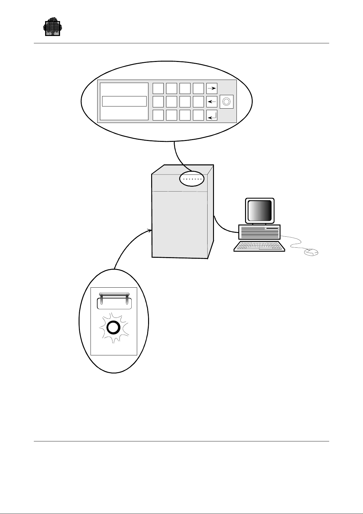
Starting Up Your System
NORMAL MODE
DPS7000/A
(front view)
2
1
5
4
78
3
F1
0
6
9
F2
SOP
(top view)
Open front door to
pull SOP outwar ds.
1
0
AC LINE
MAIN BREAKER
The Main Circuit Breaker is located
at the r ear side of t he cabinet,
behind a trapdoor.
UP = ON
DOWN = OFF
Figure 2-1 The DPS 7000/A Control Units
THE CONSOLE
Implemented on a micro-computer,
its user-interface is based on a
windowing application.
It remains an optional feature.
47 A2 53US Rev03 2-3
Page 50
GCOS 7 System Operator’s Guide
2.2.2 Introducing the DPS 7000/A Console
The first screen visible (the Control Screen) on the DPS 7000/A console is shown
below. If you are at the console, and other screens are displayed, it is always
possible to return to this one by clicking on the CTRL icon.
INITIATIVES HARDCOPY F1 TENANT F9 DISCONNECT
DPS 7 SERVICE CONSOLE PACKAGE
Linked to SYSTEM HARDCOPY ON
MO N A U G 21 09: 12:00 CONTRO L ON =
Bull
To enter a command from the Init iatives menu:
1. Pr ess <F2> fu nc tion key to obta in the CO NTR OL window.
2. Click on the INITIATIVES menu.
3. Click on th e required co mmand.
Initiative commands i nclude Power O n, Power-off, System Reset, et c . They are
described in detail in the DPS 7000/A Operator’s Guide.
2-4 47 A2 53US Rev03
Page 51

2.2.3 Powering On the DPS 7000/A
The normal operating mode of the DPS 7000/A is Automatic. Manual initialization
is not used on the DPS 7000/A when in normal operation.
1. Ensure that the console is powered on. If not, flip the console switch.
2. Ensure that the AC power switch is ON. (See Figure 2-1. The AC power
switch is located at the rear of the system. It should be up, with AC lamp lit.)
3. Activate the power-on command on the console (see procedure given further
on).
4. If you are in Automatic mode, Power On and Initialization occur without any
further intervention (see below if that is not the case).
5. Once the power-on and initializ at ion phases are over, wait for the foll owi ng
message:
hh.mm GCOS 7 RELEASE V6xx xxxx READY mmm dd, yyyy
And if that does not work...
Starting Up Your System
Last message displayed
What to do:
on the console:
I-MID xx READY You are in MANUAL mode. In this case,
1. Set automatic mode (See procedure below.).
2. Enter a SYSTEM RESET command (See procedure
below.).
IL01 OPTIONS? I: Refer to Chapter 3 Starting and Terminating a GCOS 7
Session to an swer the IL01 OPTIO NS qu est ion . (or Press
<Enter> key to load with default options).
*M INIT69 PR01
RECOVER.REPLY
(UD, CR)
You have the choice between:
- taking care of the printer PR01 (mounting paper, for
instance) and answering UD (Use Device),
- or doing n othi ng, a nswering CR (Cancel Request), and
doing without the printer.
Refer to Chapter 6 Peripheral Operations for indications
relative to printers.
47 A2 53US Rev03 2-5
Page 52

GCOS 7 System Operator’s Guide
2.2.4 Se tting the DPS 7000/A to Automatic Mode
At the console :
1. CONTROL window Press the F2 function key to obtain the C ONTROL
window.
2. INITIAT IVES menu Click on the INITIAT IVES menu, or press Alt I.
3. MODIFY INIT PARAMETE RS co mman d
Click on the MODIFY INIT PARAMET ERS
command. A dialog box appears.
4. Enter <1> Press <1> after the blinking cursor, to select Automatic
mode, then press <Enter>.
5. Press <Enter> several times
Press <E n ter> several tim es, to a ccept the values o f the
other parameters.
2.2.5 Power On or System Reset Command from the Console
To enter P O WER-ON or RESET c ommands from the console:
1. CTRL window Press F2 to obtain the CONTROL window.
2. INITIAT IVES menu Click on the INITIAT IVES menu (or press Alt I).
3. POWER ON or SYSTEM RESET commands
Click on POWER ON or SYSTEM RESET commands
of the initiatives menu.
In the case of a SYSTEM RESET, a dialog box
appear s, with two opt ions: YES a nd N O. C lic k on YES
(or enter Y) to validate the command.
The POWER ON command has no effect a t all if the
system is already powered on.
If a COMMAND COMPLETED message appears,
click on OK (or press <Enter>) to acknowledge it.
2-6 47 A2 53US Rev03
Page 53

Starting Up Your System
2.2.6 Service Commands: Reload (RL) and Restart (SR) on DPS 7000/A
2.2.6.1 Reload Procedur e
This c o mmand is used af ter a TSYS GCOS (TERMINATE_SYSTEM) comman d
or after a System Crash.
NOTE:
The RL command is only necessary if the REPEAT parameter is not in force;
see Section 3.3.8.4 Automatic Restart.
To reload the system on a DPS 7000/A
1. O b tain Ser vice Co nsol e Ca ll the INITIATIVES menu, then clic k the initiat ive,
SWITCH TO SERVICE . (<Ctrl C > on the keyboard
also works.)
2. <In sert> Press < Insert> to v i suali ze the SP: pro mpt of S POS
oper ating system.
3. SP: RL To reload GCOS 7
2.2.6.2 To Restart the System on a DPS 7000/A
This comman d is us ed to f or ce a system crash and t erminate the system cl eanly in
the case of a system deadlock, for example.
1. Obtain S er vice Co nsol e Ca ll the INITIATIVES menu, then select the initiat ive
SWITCH TO SERVICE. (< C tr l-C> on the keyboard
also works.)
2. <In sert> Press < Insert> to v i suali ze the SP: pro mpt.
3. SP: SR To restart GCOS 7.
47 A2 53US Rev03 2-7
Page 54

GCOS 7 System Operator’s Guide
2.2.7 Powering Off the DPS 7000/A
This procedure works if GCOS 7 is running. (If GCOS 7 is
not running, u se th e
POWER-OFF initiative: <F2>, <ALT-I>, <Enter> keys.)
1. Obtain S: prompt in the SYSTEM window
Press F1, then insert. If that does not work, read the
appropriate console help text.
2. TSYS GCOS PWROFF This command terminates the system, then powers off.
3. Wait for jobs to terminate
Termination time depends on what jobs are running.
Refer to Section 3.5 Terminating The Session.
NOTE:
It may be necessary to terminate the telecommunications job, using the TT S VR
TNS command.
2.2.8 Se tting Power On/Off Timers (MDPWR and DPWR Commands)
Use MODIFY_POWER_TIMER (MDPWR) and DISPLAY_POWER_TIMER
(DPWR) to control the Power ON timer and Power OFF timer. Refer to both
commands is Chapter 7 Description of the Operator Commands for further
information.
2-8 47 A2 53US Rev03
Page 55

2.3 The DPS 7000/2X0 and /3X0
The control elements of the DPS 7000/2x0 and /3x0 are represented in Figures 2-2
and 2-3.
Two things to remember about the DPS 7000/2x0 and /3x0:
1. The normal mode for pow ering on is Automatic mo de
When the system is in Automatic mode, hardware is initialized and the
oper atin g system loaded w i thout any intervention from the op erat or. The
complete procedure is described below.
Of course, it is also possible to power on or initialize in manual mode. The
procedure is described briefly below on the following pages. For more
documentation relative to these procedures, refer to the Operator Reference
Manual.
2. The system must nev er be po wered off without being terminated first
System Termination is described in Section 3. Note that it is possible to leave
the system powered on 24 hours a day.
Starting Up Your System
2.3.1 Powering On the DPS 7000/2x0 or /3x0
On the Main Distributor
Board
On the System Operator
Panel (SOP)
1. Ensure that the power supply from the Main
Distributor Board is on.
2. Check that the AC LINE indicators are ON, indicating
that the system power is ON.
3. Check that the SOP Switch is OFF (Figure 2-3).
4. Set the Diskette unit switches to ON.
On the control panels of
the peripheral controller s
5. Check that the Mains Circuit Breaker(s) are set to
ON.
6. Set the LOCAL/SYST EM switches to SYST EM, or set
the ON LINE / OFF LINE switches to ON LINE.
On the console(s)
On the SOP
7. Set the ON/OFF switch to ON.
8. Set the Mains Circuit Breaker(s) to ON. (On a
DPS 7000/3x0, set both Mains Breakers to ON.)
9. Set the SOP switch to ON.
47 A2 53US Rev03 2-9
Page 56

GCOS 7 System Operator’s Guide
The DPS 7000/2x0 or 3x0 then outputs several pages of messages, without any
oper ator inter vention r e quire d. Finally, the f ollowing mes sage app ears:
hh.mm GCOS 7 RELEASE V6xx xxxx READY mmm.dd,yyyy
******************************
You can now press the <Transmit> key to log on, entering your user-name and
password.
And if that does not work...
Last message displayed on the console:
What to do:
I-MID xx READY
You are in MANUAL mode. In this case, key in:
##MP AUTO 1 (to set automatic mode)
##FS I N I T 1 ( to reinitiali ze)
IL01 OPTI ONS?
I:
Refer to Chapter 3 Starting and Terminating a GCOS 7 Session to answer the IL01
OPTIONS questi on. (Press <Transmit> key to l oad with default options) .
*M INIT69 PR01
RECOVER.REPLY
(UD,CR)
You have the choice between seeing to the printer (mounting paper, for instance)
and answ ering UD (Use Device ) , or e l se do ing nothing an d answ ering CR (Cance l
Request).
2-10 47 A2 53US Rev03
Page 57
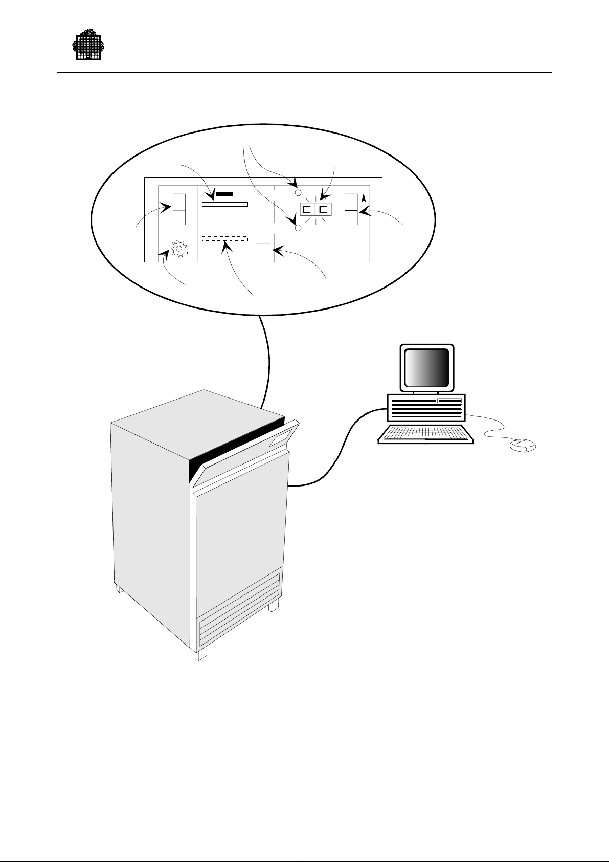
Diskette Unit
Starting Up Your System
The SOP Panel
Init SPA Switches
SOP Display
(CC is the normal code)
Main
Circuit
Breaker
Warning:
I
O
AC Line Indicator
Keep the cover
closed to avoid
accidents.
Minidisk
Init 0
Init 1
Diskette Unit Switches
SOP
Switch
The Console
The DPS7000/2X0
Figure 2-2 The DPS 7000/2X0 Control Elements
47 A2 53US Rev03 2-11
Page 58
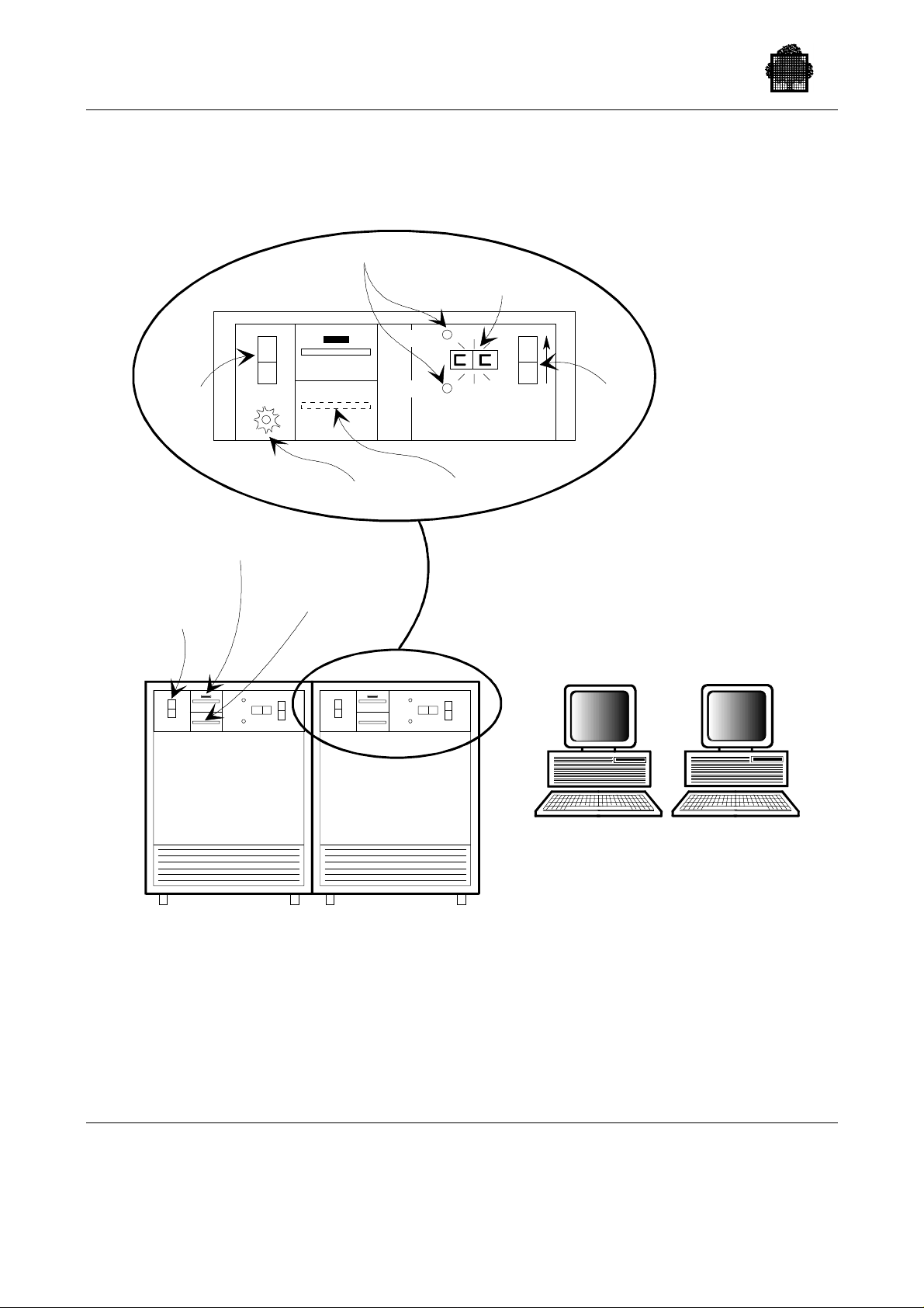
GCOS 7 System Operator’s Guide
Init SPA Switches
SOP Display
(CC is the normal code)
Main
Circuit
Breaker
Main
Circuit
Breaker
(x2)
I
O
Diskette drive (x2)
Mini Disk (x2)
Init 0
Init 1
AC Line Indicator
SOP
Switch
Minidisk
The DPS7000/3X0 has 2 main consoles:
one is called the Master Console,
while t he other on e is the
Back-up Console .
The DPS7000/3X0
Figure 2-3. The DPS 7000/3X0 Control Elements
2-12 47 A2 53US Rev03
Page 59

2.3.2 Manual Initialization on the DPS 7000/2X0 and /3X0
This is not the normal initialization procedure.
This proc e dure is not n ecessary i n the context of n ormal operation. But may be of
some use in the case of looping crashes, when the system enters a crash, reloads
automatically, crashes again, in such a way that it is not possible to regain control.
Commands keyed in by the Operat or ar e gi ven i n bo l d t y pe. Note that ##
commands can be entered at any time, even if at the same time, the console is
outp utting a flood of messa ges.
Procedure Comments
Starting Up Your System
##MP AUTO 0
To set Manual mode
##COMMAND COMPLETED
##FS INIT 1
To initialize
##COMMAND COMPLETED
I-MID xx READY
<Break>
I:LOAD0
To load SPI from the Minidisk
(LOAD2 to load from diskettes)
. . .
>>>SPI01 DEVICE LO ADER (0/2):0 To load SPOS from the Minidisk
(<2> to load from diskettes)
. . .
M SP0100 NO JOBS RUNNING IN
SERVICE PROCESSOR
SP: IN MS03 if you want t o load
GCOS 7 from MS03 disk
##FM
##MID OFF CALL
SP:IN
* IL01 OPTIONS ?
I:
When you have reached this level,
you can modify the IL01 OPTIONS,
as indicated i n section 3. Otherwis e,
you can enter <Transmit> to load
with default options.
##MP AUTO 1
When you have finished, it is
necessary to set the system back to
automatic mode.
47 A2 53US Rev03 2-13
Page 60
GCOS 7 System Operator’s Guide
Table 2-1. Functions of the DPS 7000/2X0 and 3X0 System Operator
Name Function
MAIN CIRCUIT
BREAKER
AC LINE
INDICATOR DPS
7000/X0 and 3x0
INIT SPA
PUSHBUTTON
SOP DISPLAY Indicates the current status of the SOP by means of a
SOP SWITCH When this switch is ON (s et at 1), it activates the Centra l
DISKE TT E DRI VE The Diskette dri ve is us ed if diskettes are t o be used for
DK UNIT SWITCH When this Sw itch is ON (set a t 1), it a c tivates the
Panel
When this switch is ON (set at 1), the Central Subsystem
Units are powered on.
When LIT, it indicates that system power supply is ON at
the main distributor board.
The INIT 0 switch i n itializes S PA 0.
The INIT 1 switch i n itializes S PA 1.
This can also done by typing in a command at the console.
two-digit display.
See Operator Reference Manual, Section 3, for details.
Subsystem(s). It must not be switched on before the Main
Circuit Breaker.
manual utilization.
mini-dis k n ormal ly used for initializ ation.
2-14 47 A2 53US Rev03
Page 61
Starting Up Your System
2.3.3 ASPA Configura ti on Parameters on the DPS 7000/2X0 and 3X0
The ASPA (Ant e Service Proc ess o r), which is activ ated when a DPS
7000/2X0/3X0 system is powered on, has a certain number of configuration
parameters. Some of these parameters directly affect initialization mode and
bootload devices. The values of these parameters are normally defined at
installation time.
The ASPA C on f iguration scree n is illu str ated in Figure 2-4 .
DKSL
AUTO
Select Automatic
or Man ual Mode
(see note 1)
C: ##MC
Selects mini-disk
or diskette for SPA
image loading
(see note 2)
## ASPA CONFIGURATION ##
##SPSL : (SPA SELECTION ) = 1 ?
##AUTO : (INITIALIZATION MODE ) = 0 ?
##DKSL : (SPA BOOTLOAD DEVICE ) = 0 ?
##DVSL : (GCOS BOOTLOAD DEVICE ) = MSXX ?
##PASS : (REMOTE LOG-ON PASSWORD) = KKKKKKKKKKKK ? KKKKKKKKKKKK
##IDNT : (SPA IDENTFICATION ) = XXX ?
##EPXM : (ECHOPLEX MODE ON RMS ) = 0 ?
##SPDM : (SPEED SELECTOR FOR RMS) = 1 ?
## END OF CONFIGURATION ##
DVSL
Selects the
default devic e for
GCOS loading
Figure 2-4. ASPA Configuration Screen
NOTES:
1. ##AUTO = 1 selects automatic mode
##AUTO = 0 selects manual mode
2. ##DKSL = 0 selects minidisk
##DKSL = 2 selects diskette
47 A2 53US Rev03 2-15
Page 62

GCOS 7 System Operator’s Guide
1. To displa y this sc reen a nd che ck the current va lues of the pa rameters:
Type in ##MC
2. If it is necess ary t o mo dify a parameter:
− Press <Tra nsmit> to move to next line of screen.
− Type in a new value.
− Press <Tra nsmit> to confirm.
For example, to select MS03 as the default GCOS 7 bootload device:
Press <Transmit> 3 times
Type in MS03
− Press <Tra nsmit> to confirm.
2.3.4 Service Commands: Reload (RL) and Restart (SR) DPS 7000/2X0 and /3X0 Systems
The two commands described below are only meaningful when entered after an SP:
prompt, with the console in SERVICE mode.
2.3.4.1 Reload procedur e (R L)
This c o mmand is used af ter a TSYS GCOS (TERMINATE_SYSTEM) comman d
or after a system crash.
NOTE:
The RL command is necessary only if the REPEAT option is not in force, see
Section 3.3.8.4 Automatic Restart.
To reload the system o n t he DPS 7000/2X0 or /3X0
To reload GCOS 7 (aft er a TSYS 1 command, or after a crash), pr oceed as fo llo ws :
1. ##AC Enter ##AC to switch from SYSTEM to SERVICE
2. <Break> Press <Break> to display the SP: prompt of SPOS, the
3. SP: RL To reload GCOS 7
service operating system.
2-16 47 A2 53US Rev03
Page 63

2.3.4.2 System Restart Procedure (SR)
This command is used to force a GCOS 7 crash and to terminate the system
cleanly, in the c ase of a syste m deadl ock for example.
To restart the system on the DPS 7000/2X0 and 3X0:
1. ##AC
Enter ##AC to switch from SYSTEM to SERVICE
2. <Break>
Press <Brea k > to vis ual i ze the SP: prompt o f SPOS, the servi ce oper ating sys tem.
3. SP: SR
To force a GCOS 7 crash.
Starting Up Your System
47 A2 53US Rev03 2-17
Page 64

GCOS 7 System Operator’s Guide
2.4 The DPS 7000/4xx/Cxx, DPS 7000/5x0/7xx/8x0/Dx0/Mx0 and DPS 7000/MTxX
There ar e three processor fa milies :
• the DPS 7000/4x0/4x5/Cxx/MTx1 and the DPS 7000/5x0/7xx,
• the DPS 7000/8x0/Dx0/Mx0,
• the DPS 7000/MTxx/TAxxx/TAxxxC.
The GC OS 7 op erat ing sys tem functi o ns in a very si milar manner on all thes e
platforms.
The main differe n ces betwe en the larg er and smal ler syste ms are in the perip herals:
• the larger DPS 7000/5x0/7xx/8x0/Dx0/Mx0/MTxx/TAxxx/TAxxxC systems can
inc lude a vast number of external tapes, car tridges, disks and print ers,
• the smaller DPS 7000/4xx/Cxx/MTx1 systems have the miniaturized internal
perip herals as well as a more limited nu mber of external peripherals.
2.4.1 Turning On and Off The System
In normal mode the system is power e d on by first turning on th e power switches of
each cabinet and of t he Servic e Pr o cessor co n sole. Then, the op erator simply
pushes the "on" button on the right of the S ystem Operator Panel (SOP) of the
BASIC/CSS ca binet. The SOP is the little pull-out panel, behind the front door, at
the top of each cabinet.
If th e Programmed O perator F acilit y (POP ) for an automa tic i nitia lization has bee n
loaded in your service processor, the cabinets are powered on, the hardware is
initialized and the operating system is loaded without any intervention by the
operator.
Note that it is possible to leave the system powered on 24 hours a day.
The complete procedure, in normal mode, is presented in the flowchart below:
2-18 47 A2 53US Rev03
Page 65
Starting Up Your System
Switch ON
all cabinet Breakers
Push ON button
on BASIC/CSS SOP
Automatic
SP power ON
Reinit of tenant SP
Windows started
SPV started
Starting of RLH,PWC,
TAH
Starting of PWC =
automatic PW ON
on PWC
Starting of MSH
Load Init CMU
ON TPC
(ON Timer value
reacted)
SP ON ?
Remote Site
FP ON command
on RSC console
Reinit of backup SP
Windows started
SPV started
Starting of RLK,MSH
AUTO bit set
Yes
Starting of SYC
Command INR SCC
initializing the system
using the SCC parameters
(boolload device)
Starting of GCOS channel
(LNH ...)
SIP execution
ISL execution
No
End of startup
There are ot her possibl e s cenarios for power on and initialization,
for example:
GCOS starting
- Manual power on us ing PWC (Power Control ser v ice) with the
Service Processor ON,
GCOS ready
- Automatic power on after a power shut down.
Figure 2-5. DPS 7000/4xx/Cxx, DPS 7000/5x0/7xx/8x0/Dx0/Mx0 and
DPS 7000/MTxx/TAxxx/TAxxxC Power On Procedure
47 A2 53US Rev03 2-19
Page 66

GCOS 7 System Operator’s Guide
2.4.2 Using the Consoles
Information on the Consoles:
The sys tem is deli v ered with a basic c o nfigu rat ion of 4 co nsoles. The configur ation
comprises:
1. The Tenant Console of the fou r consoles available per system, only th e tena nt
console is started automa tically at initialization.
2. The Backup console (optional).
The two consoles above are microcomputers that contain the s ervice
processor. They are on site.
3. The rem ot e service consol e (RSC) ,
4. The Remot e Workstation is de voted to ma intenance tasks. The opera tor
can not use this cons ole, bu t he or she contr ols it from the Tenant Console.
Information on Services:
The consoles r un applicat ions called services.
A service allows you to operate the service processor in window mode or in line
mode.
Eac h service has an a pprop riate function. For ex ampl e, SYC and CF G services
handle respectively Initial i z ati o n and Co nfiguration.
The Screen Presentatio n:
The first screen visible on the tenant console is shown in Figure 2-6.
RLN (Remote Line Ha ndler) service starts automatically at power on together with
SPV (SuPerVisor), PWC (PoWer Control) and MSH (Maintenance Station
Handler) services.
For more information about the services, refer to the appropriate Operator’s Guide.
2-20 47 A2 53US Rev03
Page 67
Starting Up Your System
RLH01 - Operatorless
Log-On
Welcome to RLH : Tuesday 27/02/90 19:22:06
**** RLH <PRES version 025.00> - Copyright @ BULL S.A. 1990****
**** RLH <BODY version 025.00> - Copyright @ BULL S.A. 1990****
**** RLH <SPH version 025.00> - Copyright @ BULL S.A. 1990****
RLH108 COM1 is successfully opened by RLH
RLH113 RLH is trying to connect to LOG board at : 27.2.90/19.22.17
The TENANT Service Processor is connected on L1 line
SCC VERSION 023 L1 AURIGA SP READY
02.27.90/19.22.19
##AM MI
RLH236 RMS line is enabled by Initiative at 27.2.90/19.22.19
##AM20 COMMAND COMPLETED
Ready Tuesday 27/02/90 19:22:47 Elapsed time 0:0
Figure 2-6. Screen Presentation
47 A2 53US Rev03 2-21
Page 68

GCOS 7 System Operator’s Guide
2.4.3 Service Commands: Reload (RL), Restart (SR)
Reload Procedure (RL)
This command is used after TSYS GCOS (TERMINATE_SYSTEM) or a System
Crash.
To reload the system:
1. On the tenant console, call the SYC service by clicking on its icon in window
mode, or type, EJR SYC in line mode
2. At the SYC prompt (SYC:), to restart GCOS 7, type this command:
RL [S0|S1]
S0 is for system zero and S1 for system one when a bi-system is involved.
Restart Procedure (SR)
This comman d is us ed to f or ce a system crash and t erminate the system cl eanly, in
the case of a system deadlock, for example.
1. On the tenant console, call the SYC service by clicking on its icon in window
mode, or type: EJR SYC in line mode.
2. At the SYC prompt (SYC:), to restart GCOS 7, type this command:
SR [S0|S1]
S0 is for system zero and S1 for system one when a bi-system is involved.
2.4.4 Se tting the Power On/Off Timers (MDPWR & DPWR Commands)
Use MODIFY_POWER_TIMER (MDPWR) and DISPLAY_POWER_TIMER
(DPWR) to control the Power On Timer. Refer to both commands in Chapter 7
Description of the Operator Commands for more information.
2-22 47 A2 53US Rev03
Page 69

2.4.5 Powering Off the System
From the Tenant Console
On t he Tenan t Console, u n der the PWC service, enter the c omman d:
PW OF (include the space)
This command shuts down everything except the Tenant Console itself.
To turn off t he Tenant Co nsole, enter this co mmand:
SPOF (no space)
3
IMPORTANT:
3
1
Do n o t en ter SP OF from a re m o te console. Wit h th e Tenant o ff, there w o uld be
no way to reconnect without manual intervention at the computer site itself,
which could be far away!
Starting Up Your System
From the SOP
On the SOP of the BASIC/CSS cabinet:
• Verify that you are in normal run mode.
• With the key s, sel ect ei th er t he command:
NORMAL OFF This sends GCOS 7 a request to switch OFF; the
system will switch off only when authorization returns
from GCOS 7.
or
NORMAL EMER OFF This switches off the cabinet, but without requesting
authorization from GCOS 7. It has the s ame eff e c t as
the POWER OFF initiative in the PWC service
window.
47 A2 53US Rev03 2-23
Page 70
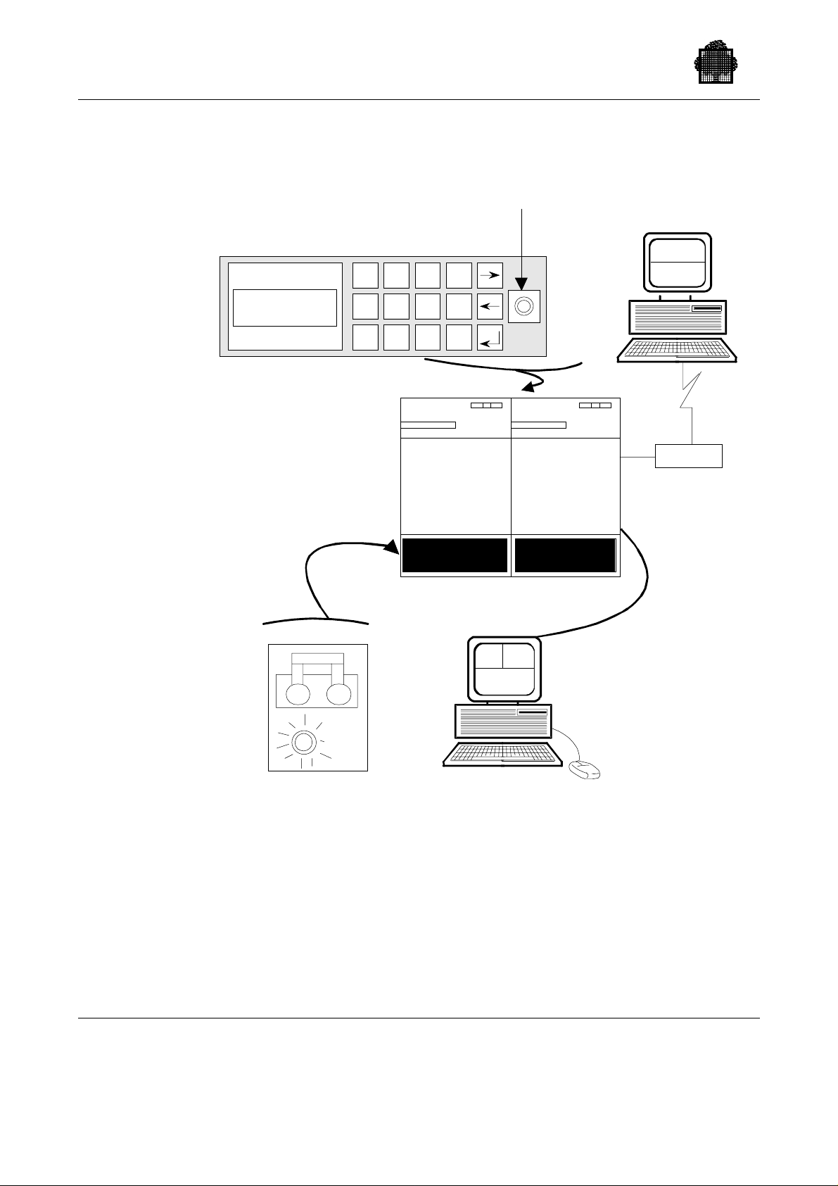
GCOS 7 System Operator’s Guide
2.4 .6 The D PS 7000/4xx/Cxx/MTx1
NORMAL
MODE
SOP
(top view)
Open front door to
pull SOP outwards.
2
1
4
7
3
56
9
8
BASIC/CSS
The "on" or "target"
push button
F1
0
F2
EXTENSION/
REMOTE
CONSOLE
RSC
SPV
MODEM
IOSS
DPS7000/4xx/Cxx/MTx1
(front view)
SPV MSH
RLH
ON ON
AC
LINE
TENANT
MAINS BREAKER
The Ma ins Breaker i s loca ted
in the rear of the cabinet.
UP = ON
Implemented on a microcomputer,
they are based on a windowing application.
They contain the service processor.
THE CONSOLES
DOWN = OFF
Figure 2-7. The DPS 7000/4xx/Cxx/MTx1 Control Units
2-24 47 A2 53US Rev03
Page 71
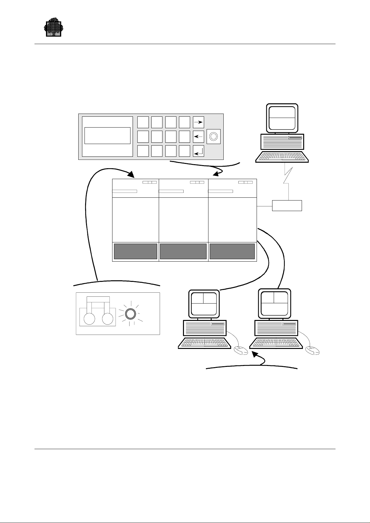
2.4 .7 The D PS 7000/5x0/7xx
Starting Up Your System
SOP
(top view)
Open front door to pull SOP outwards.
2
3
F1
0
9
F2
BASIC/CSS
NORMAL
MODE
1
4
7
EXTENSION/
56
8
IOSS
DPS 7000/5x0/7xx/8x0 /Dx0/Mx0
REMOTE
CONSOLE
RSC
SPV
MODEM
EXTENSION/
IOSS
(front view)
SPV MSH
RLH
ON ON
AC
LINE
SPV
RLH
MSH
MAINS BREAKER
The M ain s B r eaker is located
TENANT BACKUP
in front of the cabinet.
UP = ON
DOWN = OFF
THE CONSOLES
Implemented on a microc om puter,
NOTE :
units without one IOSS Cabinet and
The DPS7000/5X0 has the same control
they are based on a windowing appli ca tion.
They contain the service processor.
without the Backup console.
Figure 2-8. The DPS 7000/5x0/7xx Control Units
47 A2 53US Rev03 2-25
Page 72
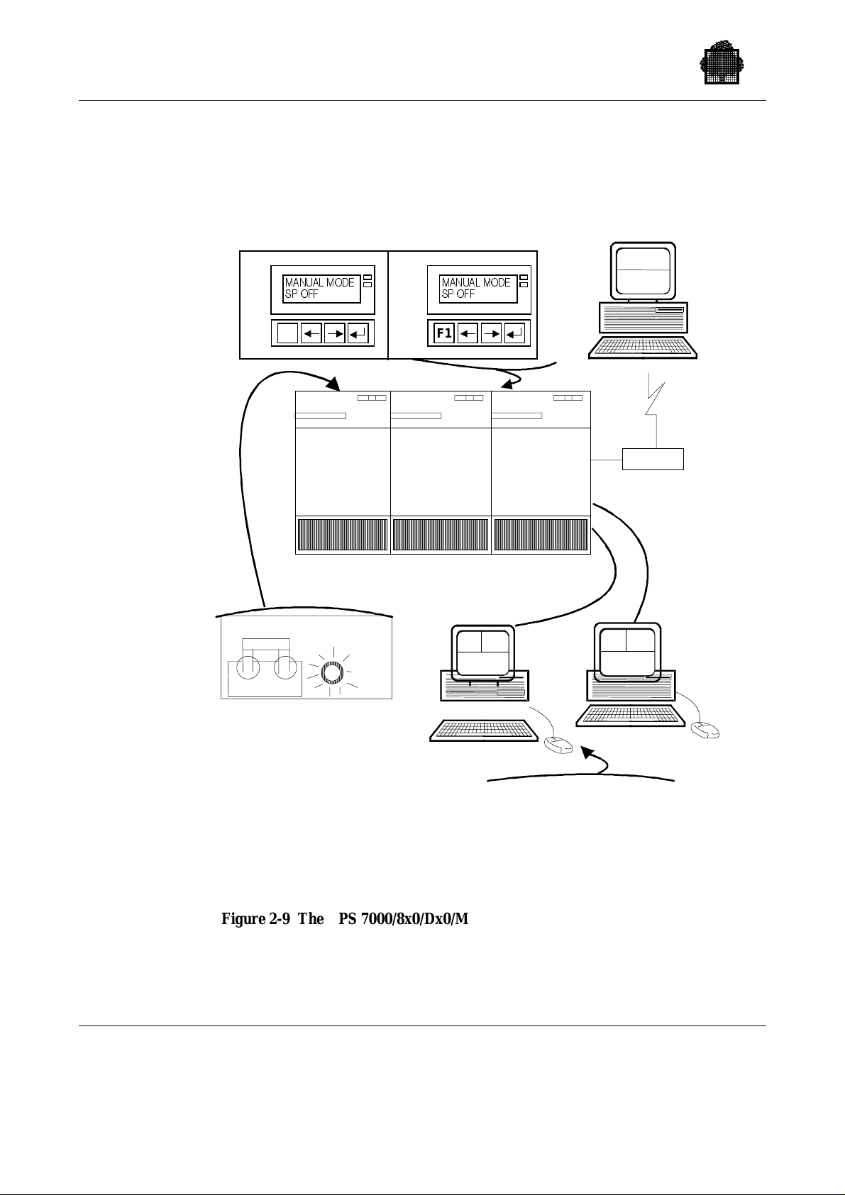
GCOS 7 System Operator’s Guide
0$18$/02'(
2.4.8 The DPS 7000/8x0/Dx0/Mx0/MT42 and UP/TAxxx/TAxxxC
SOP
(top view)
Open front door to pull SOP outwards.
0$18$/02'(
632))
F1
EXTENSION/
IOSS
632))
F1
BASIC/CSS
EXTENSION/
IOSS
DPS 7000/8x0/Dx0/Mx0/MT42 and up/TAxxx/TAxxxC
(front view)
REMOTE
CONSOLE
RSC
SPV
MODEM
SPV MSH
RLH
ON ON
AC
LINE
SPV
RLH
MSH
MAINS BREAKER
TENANT BACKUP
The Mains Breaker is located
in front of the cabinet except for
BASIC/CSS located in rear of
the cabinet.
UP = ON
DOWN = OFF
NOTE :
The DPS7000/5X0 has the same control
THE CONSOLES
Implemented on a microcomputer,
they are based on a windowing application.
They contain the service processor.
units without one IOSS Cabinet and
without the Backup console.
Figure 2-9 The DPS 7000/8x0/Dx0/Mx0/MTxx/MT42 and up/TAxxx/TAxxxC
Control Units
2-26 47 A2 53US Rev03
Page 73

3.1 Introduction
This section describes the following operations:
• Initial System Loa d.
• Operating Modes: attended and unattended.
• Loading O perations: Atten ded Mode.
• Answering IL01 OPTIONS question.
• Date and Time Management.
• Terminating the Session.
• Error Messages displayed During System Loading.
3. Starting and Terminating a GCOS 7 Session
These phases are the normal continuation from initialization, described in Chapter
2 Starting Up Your System.
47 A2 53US Rev03 3-1
Page 74

GCOS 7 System Operator’s Guide
3.2 Initial System Load (ISL)
3.2.1 Purpose
The Initial System Load ( I SL) opera tion has a tr iple purpose.
1. Loading the operating system into main memory.
2. Specifying the session characteristics, which are:
− RESTART, which may be WARM, COLD, CLEAN
− spec ifica tion as to which disk vo lumes are t o c o ntai n backi ng store fi les,
which are to be RESIDENT and which are to be SHARED with a coupled
system.
− specification of options such as INIT (AUTO, NAUTO), REPEAT, etc.
This is done by entering commands after the IL01 OPTIONS ? question.
3. Processing information left over from a previous session (e.g. dumps, PLMs,
information on jobs and their associated outputs).
3.2.2 Operations
1. The system status at the end of the previous session is displayed.
2. Question I L01 is asked which allows the s e lect ion of various options (DUMP,
3. A D UMP session is executed if required.
4. A RES T O RE session is execut e d if required.
5. The syste m checks the state of all t he d evices and sta rt s the initial AVR s
6. A CLEAN, COLD, or WARM RESTART is executed.
7. A mess age in dicat ing that GC OS 7 is availa ble is displayed.
RESTORE, CLEAN, COLD, WARM RESTART, ...) and ena bles the operator
to specify or mod if y elem ents of the session identity (resident, backing store
or shared disks, etc.). Automatic storage load is described in Section 3.3
Operating Modes.
Manual s torage load is desc rib e d in Section 3.4 L oading Operations: Attended
Mode, including the full set of IL01 options.
(Automatic Volume Recognition).
3-2 47 A2 53US Rev03
Page 75

3.3 Operating Modes
3.3.1 Operating Modes
Two op era tin g modes are available. T hes e are:
• Manual mo de, which re quires a dia log betwe e n the opera tor and the s ystem.
• Automatic (or unattended) mode.
At the end o f system initialization, a MAIN operator may log o n f rom any co nsole
with the r e quired attrib utes, by entering the proper pas sword or operat or
authorizati on when prompte d by the syste m to do s o. The op erat ing mod e of the
session is determined by the INIT option provided at IL01 with the parameters
SILENT/NSILENT, AUTO/NAUTO. The parameters NAUTO and NSILENT
indicate that the operator is going to perform the session manually whereas the
other two, AUTO and SILENT indicate that subsequent sessions will start
automatically.
Starting and Terminating a GCOS 7 Session
Note that the system catalog of messages is loaded during ISL instead of CONFIG
in previous releases. T he catalog is automa tically reloaded:
• after each RESTORE option,
• if its creation date is different from that used during the previous session.
3.3.2 Selecting a Console
If the system initiates the first exchange, the system selects the console with the
highest priority as found in the SRST.
If the operator initiates the first exchange, he should enter a break on the selected
console. In this case, the current mode becomes NSILENT and system messages
are displayed until the system is ready.
You can automatically switch from the current working console to another by
entering a break on the new console.
47 A2 53US Rev03 3-3
Page 76

GCOS 7 System Operator’s Guide
3.3.3 Unattended Mode
This refer s to the abil ity of GCOS 7 to load itse lf with out manual i nterv e ntion. If
the SILENT mode is set, then loading can take place with the console(s) off-line.
The INIT (AUTO, SILENT), and REPEAT options provid ed at IL0 1 are ass ociated
with UNATTENDED MODE.
SIL E NT only mes sages requiring the operator to take action or
AUTO means that loading options are supplied automatically
REPEAT allows software loading to be done automatically after
The library members named RELOAD_OP TION S (in the case of a G COS 7
reload) or INIT_ OPTIONS (in the case of a GCOS 7 reload preceded by a
hardware/firmware reinitialization) supply default replies to the IL01 question.
reply to questions are displa yed on the co nsole.
(on condition that the right subfiles are present; see
below).
the TERMINATE_SYSTEM command or after a
system crash.
The library member named H_SYS_REPLY supplies default replies to GCOS 7
questions whi ch are aske d duri ng initial iz ati on; it c onta ins a predefined reply for
each question key and subkey.
RELOAD_OPTIONS, INIT _OPTIONS and H_SYS_REP LY ar e stored in the
SYS.HSLLIB default source library, a nd can be modified on the site. Each record
of the file H_SYS_REPLY consists of:
KEY = XXnn [SUBKEY = dec2] REPLY = ’reply text’
KEY is the questio n key containing two lett ers and two digits.
SUBKEY is the question subkey containing two digits.
REPLY introduces the reply itself.
System components test the AUTO option and apply default values to those
ques tions for whi c h no r ep ly wa s def ined.
Of cou rse, manual opera tor interv e ntio n may be need e d to a nswer cert ain
questions, unusual requests such as device recovery or an error message preventing
successful loading.
3-4 47 A2 53US Rev03
Page 77

Starting and Terminating a GCOS 7 Session
In this unattended mode, no system messages appear on your console but they are
stored in the SYS.LOGC file. You may retrieve them later by using the
DISPLAY_CONSOLE_LOG (DCLOG) command or by producing a printout.
During softwa re loa ding, all quest ions r equest a d eferr ed reply in order to facilita te
console configuration. If an incident occurs (for example, the system cannot find a
console or is waiting for the operator to take an action), the system then enters a
dynamic wait state in which it periodically tries to dialog with the operator.
You may receive pending action messages on a local console. Once the operator
takes the required action, unattended loading continues normally.
3.3.4 Operator Commands Allowed During GCOS 7 Initialization
To activate t he system, e nter a break. During s torage load, y ou can only referenc e a
sub set of the GCOS 7 main op erat or commands:
• START_DEVI CE (SDV)
• CANCEL_REQUEST (CR)
• MODIFY_VOLUME (MDV)
• NAME_VOLUME (NV)
• DISPLAY_TIME (DTM)
• DISPLAY_CONSOLE_LOG (DCLOG)
• REPLY (REP)
• MODIFY_CONFIGURATION CLM (MDC CLM)
• DISPLAY_REQUEST (DR)
3.3.5 Console Failure
If the console in use fails or becomes unavailable, for example goes off-line, the
operator may i nterrup t the loadi ng procedure.
To select another console which is to be dynamically reconfigured, see Section
3.3.2 Selecting a Console.
If th e s yste m sends a message r equiring th e operator to take a c tion, for examp le,
setting a device on-line or physical exchange of a device, the system re-issues the
message until a cons ole becomes available.
47 A2 53US Rev03 3-5
Page 78

GCOS 7 System Operator’s Guide
3.3.6 System Startu p
Once t he loading is completed, and just before the system is declared ready, a
sta rtup proce dure named SYST EM is exe c ute d automatic ally before an y queue d
job is restart ed . Th e absence of the member SYST EM in the libra ry
SI TE.STARTUP does n o t preve n t the s y st em fr om oper ating.
The purpose of the SYSTEM startup is to execute a set of installation-specific
com mands before operat ors or users log o n.
The startup can:
• start telecommunication sessions,
• set up specific parameters, for example, job classes.
For sites without a local console, these facilities allow you to:
• connect a remot e operator,
• start a RMOS session (see further on).
Interactive processors cannot be activated on the SYSTEM startup.
SYSTEM startup is a set of commands (by default, these commands are in GCL
language) with sequences which may depend on switches themselves set by the
type of restart:
SW1 is set on for a WARM RESTART.
SW2 is set on for a COLD RESTART.
SW3 is set on for a CLEAN RESTART.
SW4 is set if a dump is present in the SYS.SYSDUMP file.
SW5 a nd SW6 concern cou pled syste m s configurations:
SW5 = 0 and SW6 = 0 the local system is not configured as part of a coupled
system (it is independent).
SW5 = 1 and SW6 = 0 coupled systems configuration: the local system is
even.
SW5 = 0 and SW6 = 1 coupled systems configuration: the local system is odd.
NOTES:
1. The SYSTE M startup c omman ds can also be in JC L, in which case th e
switches are nu mbered from 0 to 5.
2. A TDS job must not be submitted in the system startup as this can cause
unexpected TDS beh avior.
3-6 47 A2 53US Rev03
Page 79

3.3.7 System Ready Transition
When the SYSTEM startup is executed, the Operator Message Handler (OMH) is
automatically activated in job class Z. This job becomes an integral part of
GCOS 7.
During the initialization of the OMH job, system messages are not normally
disp layed on th e operator terminal and br eaks are inhibited for a few moments.
However, no messages are lost and if you wish, you can retrieve them from the
SYS.LOGC file.
If OMH does not star t, you cannot st art a job. To correct the software error, call the
Service Center. S ee the Operator’s Guide for the platform concerned for an
expl anation of the ma intenance pr ocedures.
Because you may wish to operate in unattended mode, or do remote operations, the
system, when ready, does not r e quest the MAI N oper ator to log on.
Starting and Terminating a GCOS 7 Session
3.3.8 Loading Operations : Unattended Mode
Certain operations c an b e performed without op erat or interventio n:
• Initial System Loa d (I SL)
• restart after a crash.
The paramet ers which affect automatic operations are the AUTO parameter of the
INIT option and t he REPEAT option provi ded at IL01.
The AUTO parameter permits an automatic reply to the IL01 OPT IONS question
and R E PEAT permits sof twa re reloading without operator intervention after a cr a sh
or a fter TE R MINATE_ SYSTEM. The IN I T and R EPEAT opt i ons ca n be dis playe d,
set or modified dur ing the GCOS 7 s es sion by using the
DISPLAY_RESTART_OPTIONS (DRSO) and MODIFY_RESTART_OPTIONS
(MDRSO) commands.
47 A2 53US Rev03 3-7
Page 80

GCOS 7 System Operator’s Guide
3.3.8.1 DISPLAY_RESTART_OPTIONS (DRSO) Command
Displays the fol lowi ng system initializat ion parameters:
• automatic restart option
• silent restart option
• automatic repeat option
• the initialization device
{DISPLAY_RESTART_OPTIONS}
{DRSO }
EXAMPLE:
DRSO
>>16.13 AUTO=0/0 SILENT=0/0 REPEAT=0
SYSTEM DUMP AVAILABLE
ANTESP SWITCH IS OFF INIT=MS17
❑
NOTE:
For a des c ription of the va lues displayed, refer to the DRSO c ommand in
Chapter 7 Description of the Operator Commands.
3.3.8.2 MODIFY_RESTART_OPTIONS (MDRSO) Command
Modifies the system initialization options for the next restart only, after a crash or a
TERMINATE_SYSTEM command. (See Section 3.3.8.3 Automatic Reload for
modifying initialization parameters for all subsequent restarts.)
{ MODIFY_RESTART_OPTIONS }
{ MDRSO }
[REPEAT = bool]
[AUTO = bool]
[SILENT = bool]
[{DEVICE} ]
[{ } = MSxx ]
[{DV } ]
3-8 47 A2 53US Rev03
Page 81

Starting and Terminating a GCOS 7 Session
Parameters
REPEAT when 1, the next system shutdown or crash is
immediately followed by a restart, reload or reinitialization (depending on the system and the cause
of th e shut down ) without a ny operat or int erventio n.
This operation takes into account the disk unit
identification stored in the service processor through
the DEVIC E parameter. Conse quently, when REP EAT
is set to one the operato r must check the d evice
identification stored in the service processor. When 0,
the next system shutdown will require a manual
intervention f rom an operator to restart the syste m. In
the case of CRASH the system is restarted and
reloaded automatically, taking into account the unit
that was the system disk in the current session. This
oper ation is nec es sary to process c onsistently the
DUMP related to the CRASH.
AUTO when 1, the next system restart (whether with or
without operator intervention) is automatic, i.e. does
not ask t he oper ator any question, prov ided t hat d ef ault
replies have been stored in the RELOAD_OPTIONS
library member, as appr opriate. When 0, the ne xt
system res tart is r u n by the operator wh o is as ked
questio ns.
SILENT when 1, the next system restart (with or without
operator intervention) results in no message being
issued on the operator console; when 0, messages are
issued.
DEVICE this parameter is used only on DPS 7000 systems. It
specifies the disk unit from which the operating system
is to be initialize d. Unli k e the ot h er par ameter s, this
option is retained for all subsequent system
initializations until another MDRSO command is
issued.
Constraints
If AUTO = 0 then SILENT is ignored.
47 A2 53US Rev03 3-9
Page 82

GCOS 7 System Operator’s Guide
EXAMPLES:
MDR SO AUTO SIL ENT ( Next restart asks no question and is sues no mess age. )
MDR SO REPE AT = 0 (Manual intervent ion is required to initiate the next
❑
To displa y the repeat, rest a rt, s ile nt rest art, and initial iz ati o n device opt ions, use th e
DISPLAY_RESTART_OPTIONS command described in Section 3.3.8.1 above.
3.3.8.3 Automatic Reload
The "IL01 OPTIONS" question is asked at the local console during a Reload
(su bsequent to a TS YS command or a crash), on con dition tha t INIT (NAUTO) is
set. If INIT (AUTO) is set, answers are read from disk. Note that setting INIT
(AUTO) at the IL01 OPT IONS question applies to all subsequent reloads, but that
the value set by the MDRSO command applies only to the next reload.
restart.)
When the whole system is (re)initialized in unattended mode (auto-hardware mode)
the reloa ding of GCOS 7 is automa tic, e ven if AUTO was not set at the end of the
GCOS 7 session. In this case the INIT_OPTIONS memb er is used to answer the
ILO1 OPTIONS question.
3.3.8.4 Automatic Restart
This is controlled by the REPEAT option provided at IL01 parameter. If repeat is
set to OFF a manual restart is needed after the end of a GCOS 7 session.
REPEAT can be set so that an automatic restart is made after the end of session or a
crash. One way is to use the MDRSO command, but this is o nly effe c tive for t he
next restart. The other way is to set the REPEAT Option, with no parameters, as
one of the replies to the IL01 question. You can additionally use the minutes
parameter of the REPEAT Option, which allows the user to set a minimum time
between auto mat i c restart s of cras h es. If t wo consecutive crashes occur duri n g this
time, Auto mode is stopped.
3-10 47 A2 53US Rev03
Page 83

3.3.8.5 Cancelling Auto Mode
There are two ways to cancel Aut o mode:
• By using the MDRSO AUTO=0 command, when GCOS 7 is running. After a
crash or a shutdown, for the next GCOS 7 restart only, the IL01 question will be
asked at the system console.
• By using the prerecord e d reply, INIT( NAUTO) , to t he I L01 question, after a
crash or shut down, for example. In this case, the Auto Mode cancellation only
becomes effective for the subsequent GCOS 7 sessions, but not the session being
started.
Modification to the preregistered answers to IL01 must be done by an update to the
RELO AD_OPTIONS lib rary member.
NOTE:
By using both of the above possibilities you can cancel Auto Mode for the next
and subsequent sessions.
Starting and Terminating a GCOS 7 Session
3.3.8.6 Dump Facilities in Automatic Mode
AUTO and REPEAT modes are necessary for an automatic restart in case of
crashes. For dump storage after crashes in automa tic mode the following
commands should be registered in the RELOAD_OPTIONS library member:
DUMP( D ISK) This permit s the dump opt ion commands to be
DUMP_CD (O,volnm,DEF; EXEC,DPS_STD;END;)
In the case of a crash dump in automatic mode the question CRASH
COMMENTS? is not issued and the reply "AUTO" is provided by the system.
See Section 3.4.3.5 DUMP for a detailed description of Dump facilities.
retrieved from DUMP_CD parameters, instead of from
th e con sole.
This stor es the co mmands which sa v e the GCO S 7
dump in the SYS.SYSDUMP file. A standard dump is
produced.
47 A2 53US Rev03 3-11
Page 84

GCOS 7 System Operator’s Guide
3.3.8.7 Abnormal Events During First Phase of GCOS 7 Loading (ISL)
In AUTO mode, any abnormal event occurring during the first phase of GCOS 7
loading (ISL) and for which no response is automatically provided by the system or
for w h ich an operator action is nee ded, l eads to disp lay of t he related I Lxx er ror
message prefixed by the "##FW" character string:
##FW ILxx .......
The system then enters an endless lo op. T h e error must b e cor rected and a new
Initial Sys tem Load ex e c uted, or the hardwar e and firmware must be ma nually
rein itia lized as describe d in Chapter 2.
If an I/O error occurred on system files (SYS.BKSTi, SYS.LIBi, SYS.PVMFi,
SYS.TVMFi) during last GCOS session, the message IL21 will be displayed and
the AUTO mode will be stopped (IL72). In this case, the IL01 question is then
displayed to the main operator in order to modify the corresponding list of system
files.
3-12 47 A2 53US Rev03
Page 85

Starting and Terminating a GCOS 7 Session
3.4 Loading Operations: Attended Mode
The ISL ba nner consists of two or three lines. The first line shows the technical
status of I SL component s:
>>> ISL-vvv.v xx -n (aa bb ...) / yy -m (cc dd ...)
where
vvv. v = version.revision
xx -n (aa bb ...) refers to SERs (S oftware Error Report) for INIT of
ISL, where:
xx = highest SER rank
n = nu mber of missing SERs
aa b b . .. = ra nks of mis sing SERs
yy -m (cc dd ...) refers to SERs for DPS of ISL, where:
yy as for xx
m as fo r n
cc dd ... as for aa b b
The second line shows the current local date, time and the time deviation value,
when available:
>>>HH:MM:SS month DD,YYYY TIMEDEV=+01.00
NEW TIMEDEV is u sed instead of TIM E DEV if the time d e viat ion value ha s
changed.
The thi rd lin e sh ows the cha nne l n umber of t he ISL device (LOAD PCLC)
preceded by the channel number of the hardware device (INIT PCLC), when Initial
System Load occurs just after the INIT phase:
>>>LOAD PCLC = Chn1
or
>>>INIT PCLC = Chn1 LOAD PCLC = Chn2
47 A2 53US Rev03 3-13
Page 86

GCOS 7 System Operator’s Guide
3.4.1 System Previous Status
The system indicates whether or not a System Dump is available as a result of the
previous session.
1. If no dump is a vailab le the mes sage issu e d is :
IL28 NO PREVIOUS DUMP
2. If a dump does exist the message is:
SYSTEM PREVIOUS STATUS ON mm/dd/yy AT hh:mm:ss
followed by one the following:
- SYSTEM EXCEPTION }
} ON J = xx P = xx CLASS = xx TYPE = xx
- HARDWARE FAILURE }
- CALL TO PANIC FROM J = xx P = xx CODE = xxxx
- CHANNEL EXCEPTION ON MCxx PC = xx LC = xx
- UNKNOWN
- SYSTEM RESTART
3. If the last GCOS 7 session was terminated through the
TERMINATE_SYSTEM command, the me ssage is:
SYSTEM PREVIOUS STATUS ON mm/dd/yy AT hh:mm:ss
SHUTDOWN
4. If the last GCOS 7 session was terminated when the back-up battery had
fail e d or was discharged, no du mp is availab le and t his message is disp layed :
SYSTEM PREVIOUS STATUS ON mm/dd/yy AT hh:mm:ss
EMERGENCY SHUT DOWN
5. In all cases the s y st em then asks the qu estio n * IL01 OPT ION S ? in order to
determine what work is required.
NOTE:
A S ystem Dump, when present, must be processed by a Dump Session during
the subsequent automatic loading, either to be printed or stored on disk. This is
nec es sar y because when the dump is taken, onl y some segments in me mory a re
stored. Other s eg ments are dumped either from memory or ba cking store and
are modified by the new session. If the system previous status was
SHUTDOWN or EMERGENCY SHUT DOWN, no dump is available because
the dump area contains no valid information. Any attempt to perform a dump
session is r ejected.
3-14 47 A2 53US Rev03
Page 87

3.4.2 IL01 Options
NOTE:
Examples of answer s to IL 01 OPTION S quest ion a re give n in S ection 3.4.7
Example of Answer to the IL01 OPTIONS ? Question.
The answer given to the IL01 question directs the remaining loading operations.
This answer ca n cons is t of several elements ch osen by the operat or, depen din g
upon the following:
• Whether or not a Dump session should be performed.
A dump session is needed if the previous session terminated abnormally and if a
dump is available. A dump session allows the dump to be printed on the line
printer, dis played at the op erat or cons ole, or saved on a disk f or later processing.
At the end of the Dump Session, the IL01 question is displayed again.
• Whether or not a Restore Session is needed.
• Whet her or not a Cold Restar t or a Cl ean Restar t should be performed.
The default option - a Wa r m Restart - is the usual case; sometimes a Cold
Restart and, in rare circumstanc e s, a C lean Res tar t is required.
Starting and Terminating a GCOS 7 Session
• Whether or not MAM (Message Access Method) is to be included as parameter
in the answer to the IL01 question to define handling of telecommunication
mes s a g e queu es .
The answer to Ques tion I L01 ca n als o establ i sh the status of the sessio n by
indicating or modifying the f ollowing:
• the list of resident disks
• the l ist of b acking st ore disks
• the list of shared disks (coupled systems)
• the behavior of the s yste m for t he next storage l oad
• the behavior of the system for the next system interruption.
After normal shutdown, the operator simply presses the EXECUTE (or
TRANSMIT) key to perform a Warm Restart. T he date and time are current; the
list o f resident, backi ng store or shared disks is un chang e d, un less mes sage IL16
has been displayed before the IL01 question.
47 A2 53US Rev03 3-15
Page 88

GCOS 7 System Operator’s Guide
3.4.3 Answering the IL01 Question
After indicating the system previous status, the system asks the question:
* IL01 OPTIONS ?
and the op erat or repl ies wi th on e or mor e comma nds fr om the list shown in the
following two pages. This answer directs the remaining loading operations and
specifies the type, status and characteristics of the s ession. These commands are
described in detail in the following Sections.
NOTES:
1. The maximum length of element lists (elements between left and right
parentheses) is 255 characters.
2. The separator of elements inside element lists is the comma, except for the
DUMP_CD command where a se mi - col on is us e d inst ead.
3. The separat or of t he ISL opt ions defined b y the various fo llowing key
words may be a comma, semi-colon or blank.
[{BKST(/[,volnm1, ... , volnm15]) }]
[{DATE(mm.dd.yy/hh.mm.[ss]) }]
[{ [ {* } ] }]
[{ [ {BANNER} ] }]
[{DISPLAY[({STATUS})] }]
[{ [ {TIME } ] }]
[{ [ {OPTION} ] }]
[{DISK([libnm..]member-name[:volnm] ...) }]
[{ [ {CONS} ] }]
[{DUMP[({ })] }]
[{ [ {DISK} ] }]
[{DUMP_CD( IL03 response ; [ IL03 response ;] ...)}]
[{ {ON } }]
[{HA({ }) }]
[{ {OFF} }]
[{ {CONS } }]
[{HELP({ }) }]
[{ ? {PRINTER} }]
3-16 47 A2 53US Rev03
Page 89

Starting and Terminating a GCOS 7 Session
[{ [ {NAUTO} {NSILENT} ] }]
[{INIT[({ },{ })] }]
[{ [ {AUTO } {SILENT } ] }]
[{LIB(volnm0 [ ,volnm1, ...volnm15]) }]
[{ [ {YES }] }]
[{MAM[({REFORMAT})] }]
[{ [ {NO } ] }]
[{NSYSSTUP }]
[{ [ {11 } [ {6
}] ] }]
[{PAGESIZE[({ } [*{ }])] }]
[{ [ {n[.m]} [ {8}] ] }]
[{PVMF(volnm0[,volnm1, ...volnm15]) }]
[{ {LIB[,PVMF]} }]
[{REFORMAT({ }) }]
[{ {PVMF[,LIB]} }]
[{ {OFF} }]
[{REPEAT({ }) }]
[{ {mm } }]
[{RESIDENT(volnm1[,volnm2, ...volnm10]) }]
[{ {WARM } }]
[{RESTART({COLD }) }]
[{ {CLEAN} }]
[{RESTORE[(parameter-list)] }]
[{SHARED(volnm1, volnm2,...volnm36) }]
[{SHARED2(volnm37,... volnm72) }]
[{SHARED3(volnm73,... volnm108) }]
[{SHARED4(volnm109,... volnm144) }]
[{SHARED5(volnm145,... volnm180) }]
[{SHARED6(volnm181,... volnm200) }]
[{SPOOL(max, cache-option, cache_size, domain1, }]
[{ [ ...domain20 ] ) }]
47 A2 53US Rev03 3-17
Page 90

GCOS 7 System Operator’s Guide
[{ {WARM } }]
[{SYSQM({CLEAN }) }]
[{ {BACKUP} }]
[{ {+} }]
[{TIMEDEV({ } hh [.mm]) }]
[{ {-} }]
[{ {ON } }]
[{TRC({ }) }]
[{ {OFF} }]
[{TVMF(volnm0[,volnm1, ...volnm15]) }]
3.4.3.1 BKST
BKST(/ [,volnm1,volnm2,.....volnm15] )
This option sp ecifi es the disk volumes w hich c ontain the temporary bac king store
files SYS.BKST, SYS.BKST1 up to SYS.BKST15. The first volume specified is
the syste m disk w hich contains S YS.BKST, the second volu me contains
SYS.BKST1, the third contains SYS.BKST2 and so on up to SYS.BKST15. The
slash "/" mus t be used instead of volume name to specify t h e s ystem disk. The
SYS.BKST should be on the system disk. If the first media name is not the system
disk ("/"), the following message is displayed:
VM04 FATAL: ONLY / IS ALLOWED AS A MEDIA FOR SYSTEM BACKING STORE
The system then enters an endless loop. A new storage load must be performed and
the operator mus t ent er / to sp ecify t he volume na me of SYS. B K ST fil e.
The f ile SYS.BKST is a ma n datory file. A session c annot take p l ace without it. The
absence or the error in opening this file causes the f ollowing message to be
displayed.
VM06 FATAL: IT HAS BEEN IMPOSSIBLE TO OPEN SYSTEM BACKING STORE
The system then enters an endless loop. A new storage load must be performed.
Any volume name between volnm1 to volnm15 can be omitted indicating that the
corresp ondin g back ing store f i le does not exist or is not to be used.
NOTE:
When a volume is remo v e d, the commas must remain.
3-18 47 A2 53US Rev03
Page 91

Starting and Terminating a GCOS 7 Session
The list of volumes is used during the initial checking of device states and is
retained from session to session even if, in the mean time, the system has been
powered off. The command needs to be specified only during the f irst storage load
following the creation of a new system disk or when it is required to change the list
of ba c king s tore volumes.
The backing store volumes must be online and in READY state when the load is
performed, otherwise the following messages are displayed:
IL61 MEDIA NAME NOT AVAILABLE FOR FILENAME
IL62 GIVE MEDIA NAME OR REPLY CR
The op erator must en ter the name of th e volume wher e the given file is allocated.
The a bsenc e or an error in opening non mandat ory files, i.e., SYS .BKST1,
SYS.BKST2, . .... ., SYS.BK S T15 produc e s the foll owing warning me ssa ge.
VM08 WARNING : THE sys.bksti HAS NOT BEEN OPENED
and the corresponding backing store file is not used for the session.
If the BKST contains only one file, the following message is displayed:
VM09 WARNING : NO OTHER PAGING BACKING STORE THAN THE SYSTEM
BACKING STORE IS ACTIVE
Disk mirroring is not supported on BKST volumes. If a MIRROR disk is declared
in the BKST option, it is rejected with the message:
IL80 volnm: DEVICE MIRROR FORBIDDEN UNTIL END OF
INITIALIZATION
The c oncerned BK ST fil e is ign ored, message IL 61 is sent t o the opera tor console,
and quest ion IL 62 must be answered. Refer to t he Mirror Disks User’s Guide for
further details.
If all the BKST files are inactive, the following message is displayed:
VM10 FATAL: AT LEAST ONE BKST FILE IS COMPULSORY
The system then enters an endless loop. A new storage load must be performed. An
error while loading or unloading the system structures produces one of the
following messages:
VM01 FATAL: ERROR WHILE LOADING A SEGMENT FROM THE SYSTEM BACKING
STORE
VM02 FATAL: ERROR WHILE WRITING BACK A SEGMENT IN THE SYSTEM
BACKING STORE
The system then enters an endless loop. A new storage load must be performed.
47 A2 53US Rev03 3-19
Page 92

GCOS 7 System Operator’s Guide
However, it may be necessary to reformat the system disk depending on the
Input/Output completion code. (Refer to Section 3.4.3.22 RESTORE).
The backing store volumes, other than the volume supporting the SYS.BKST file,
ar e not normally resident. Those which are requ ired to be reside nt must be declared
in the RESIDENT option.
All disks declared in the BKST option have the BKST attribute (a s r eturned by the
DHW op erat or command), except for the syst e m d i sk (c ontainin g the SYS.BKST
file), which has the SYSTEM attribute.
3.4.3.2 DATE
DATE(mm.dd.yy/hh.mm[.ss])
3
IMPORTANT:
3
1
This command should be used only in ver y exceptional circumstances, for
example if the S er vice Processor TIME-OF-DAY device (DPS 7000) is not
working.
When absolutely essential this option can b e u sed t o set th e reference dat e and
time of the GC OS 7 session, where mm.dd.yy are numerical representations of the
mont h, day and year and hh.mm.ss the time of day i n hour s, minu tes and se c onds.
The values may be entered as one or t wo digit s as a pprop riate. The reference date
and t ime entered wit h the D ATE option are used only f or th e c urrent s es sion and
ar e not reta ined from ses sion t o session.
At the next reload of GCOS 7, the reference time is taken from the Service
Processor. The local time is then calculated by the algebraic addition of the
reference time to the time deviation value set with the TIMEDEV option.
If an invalid date is given the following message appears:
IL44 DAY/TIME M.D.Y/H.M [.S] ?
and t he operator mus t reply with a valid da te and time, for ex amp le:
I: 06.30.88/14.23.30
3-20 47 A2 53US Rev03
Page 93

Starting and Terminating a GCOS 7 Session
Then the system compares the local date and time resulting from the new reference
time entered by the operator with the previous status date and time. If the current
loca l date and time is lower, the fo llowi ng messages a re disp laye d:
>>> PREVIOUS LOCAL DATE : hh:mm:ss MMM dd, yyyy TIMEDEV = shh:mm
>>> CURRENT LOCAL DATE : hh:mm:ss MMM dd, yyyy TIMEDEV = shh:mm
IL70 SYSTEM WILL BE FROZEN
IL70 DO YOU AGREE (Y OR N) ?
s is either - or + . Wh en the time dev i at ion v alue has been mod ified the cha racter
string "NEW T I MEDEV " is used inst ea d "TIMEDEV" i n the "CURRE NT LOCAL
DAT E" mes sa g e.
The answer Y (yes) indicates that the operator agrees not to have the local time set
back (an After Journal exists on the site): the system will be frozen until the
current local time passes the previous status local time. The answer Y is forced in
AUTO mode.
3.4.3.3 DISK
When t he an swer is not equ al t o Y (yes) the IL01 OPTIONS qu estion i s aske d
again in order to update the date or time deviation values or to continue the
processing by pressing "Enter".
DISK([libnm..] member-name [ :volnm])
This option can only be used alone. It spec ifies that all the answers to the IL01
OP TIONS? question are in the named source library me m ber. Default values are
SYS.HSLLIB as the source library, and the system disk as the volume. After this
answer, in the c urrent session, a n swers to the IL01 ques tion a re r ead f rom the
name d source library member.
When the me mber addr es sed by the DISK opt ion c onta ins a n errone ous op tion, a
synt ax error mes sage is displayed and t h e I L 01 OP TION S questi on is s e nt again to
th e o perator.
When a libra ry memb er is giv e n, it is retained from sessio n to session.
Cons e quent ly, wh e n the AUTO mode is used s ometime later, this libr ary mus t
cont ain the RE LOAD_OPTIONS or I NIT_OPTIONS a nd H_SYS_R EPLY
memb er s .
47 A2 53US Rev03 3-21
Page 94

GCOS 7 System Operator’s Guide
3.4.3.4 DISPLAY
[ {* } ]
[ {BANNER} ]
DISPLAY[( {STATUS} ) ]
[ {TIME } ]
[ {option} ]
The operator should use this option to display the followi ng:
* The st ar (d efault value) means the fo llow ing IL01
opti ons are displaye d: BKST, DI SK, DUM P,
DUMP_CD, HA, INIT, LIB, MAM, PAGESIZE,
PVMF, REPEAT, RESIDENT, RESTART, RESTORE,
SHARED, SHARED2, SHARED3, SHARED4,
SHARED5, SHARED6, SPOOL, TIMEDEV, TRC,
TVMF.
BANNER The ISL banner is displayed.
STATUS The system previous status is displayed.
TIM E The current local time is disp laye d.
option Displa ys the va lue of any other I L01 op tion.
The * IL01 OP TION S? question is aske d again aft er the d isplay.
The list of resident or shared disks displayed is from the previous ISL, it does not
take into accou nt an y modif ications that may hav e been made du ring p revious
GCOS 7 sessions.
This optio n c annot be us e d w hen stored i n a libr ary memb er.
3
IMPORTANT:
3
1
Use the DISPLAY (TIME) option to display the current local date, time and
time deviation values. However, (DATE) and DISPLAY (TIMEDEV) give the
last valu es ent ered under the DATE and TIMEDEV options of th e IL01
questio n. Thes e could be v ery old.
3-22 47 A2 53US Rev03
Page 95

3.4.3.5 DUMP
3
1
Starting and Terminating a GCOS 7 Session
[ {CONS} ]
DUMP[( { } ) ]
[ {DISK} ]
This option allows the operator either to print/display the dump left at the end of
the previous session or to store it on disk (in the SYS.SYSDUMP file) to be
subsequently printed or interactively analyzed by the DPAN utility.
3
IMPORTANT:
If a dump is not processed by a dump sessi on dur ing GC OS 7 loading, it will be
corrupted by the current session, overwriting main memory and the backing
st o re where most of t he dump info rmation i s found .
The dump session dialog may be entered:
• from the console. This is done by answering question IL01 with the command:
DUMP or DUMP(CONS).
• from disk. This is done by answering question IL01 with the command:
DUMP(DISK)
If th e DUMP comma nd is is sued, but no dump is available (e.g. ther e has bee n a
normal termination of the last GCOS 7 session), the following message is
displayed:
IL28 NO PREVIOUS DUMP
In this case, the dump session is terminated and the IL01 question is displayed
again.
1. DUMP or DUMP(CONS)
If a dump is available from the previous GCOS 7 session, then the following
question is ask e d :
IL03 DUMP?
The operator a nswers this quest ion with on e function at a time and the
question is repeated until the dump session ends. Termination is done by
entering END and pressing the EXECUTE or TRANSMIT key.
47 A2 53US Rev03 3-23
Page 96

GCOS 7 System Operator’s Guide
NOTE:
By using th e H ELP direct ive with IL03, you c an obt ain t he synt ax of all the
DUMP commands.
To send a summary of the dump to the line printer, enter M in reply to the IL03
question and comments in reply to the IL14 message, but see Note below.
* IL03 DUMP? M
* IL14 CRASH COMMENTS?
I: (Enter your comments.)
...
* IL03 DUMP?
where M indicates that a mini dump (Mini Memory) is to be sent to the line
printer
NOTE:
This f acility should be used only as a last resort, if G COS 7 cannot otherwis e be
restarted.
*IL14 CRASH COMMENTS gives the operator an opportunity to give any
useful comments on the fir s t page of the dump printout. (If more than one line
of comments are to be given, each line must be terminated by a hyphen.).
The c haracter i stics of the paper dimensions are t aken from th e I SL option,
PAGESIZE.
To store a standard dump on disk, the following must be entered:
*IL03 DUMP? O,[efn:] volnm,DEF
*IL03 DUMP? EXEC,DPS_STD
where efn is the external fi le name ( defaul t is SYS .SYSDUMP) , a n d volnm is
the volume name of the disk which holds the SYS.SYSDUMP file. If it is the
System disk, volnm can be replaced by "/". Note that the O (Outfile) in the
oper ator reply is alp habet ic .
The SYS.SYSDUMP file can be put on any disk. The dump overwrites any
previously stored dump on the SYS.SYSDUMP file, as only one dump at a time
may be written to this file.
Thus if this file already holds a dump from a previous session, which must be
kept or which has not b een pr int e d, and a new dump occ urs , the new dump must
be printed (using the M function previously described to send it to the line
printer). One a lternative is to use another disk to hold the SYS. SYSDUMP file,
if one is available. Another alternative is to use a diff erent file on the same disk.
3-24 47 A2 53US Rev03
Page 97

Starting and Terminating a GCOS 7 Session
It is also possible to use a self defined dump procedure using
"EXEC_LIB,library-na me :voln m" and "EXEC,memb er- name" as answers t o
the ILO3 DUMP? question.
To change the default library name, the following can be entered:
*IL03 DUMP? EXEC_LIB, libnm : volnm
EXEC_LIB defines the source library (libnm) to be opened for access to the
subf iles named in subsequent E XEC comman ds. The default libn m is
SYS.HSLLIB.
The EXEC command starts the execution of the dump commands as read from
the named su bfil e. DPS_STD is the st andard dump sequ e nce sou rce file. T he
IL01 question is reissued after dump commands, except in Auto Mode.
2. DUMP (DISK)
In this case, the answers to the IL03 question are entered from disk.
The answers must have been written previously on disk by answering
questio n I L01 w ith DUM P_C D opti on (see Section 3 .4.3.6 DUMP_CD,
below).
3. The DPAN Utility
DPAN is a dump analyzer running under GCOS 7 which provides the operator
with:
− a dump saving facility on tape (DP_SAVE)
− a dump printing faci lit y (DP_ P RINT).
See Appendi x B Calling Systems Utilities for a detailed description.
47 A2 53US Rev03 3-25
Page 98
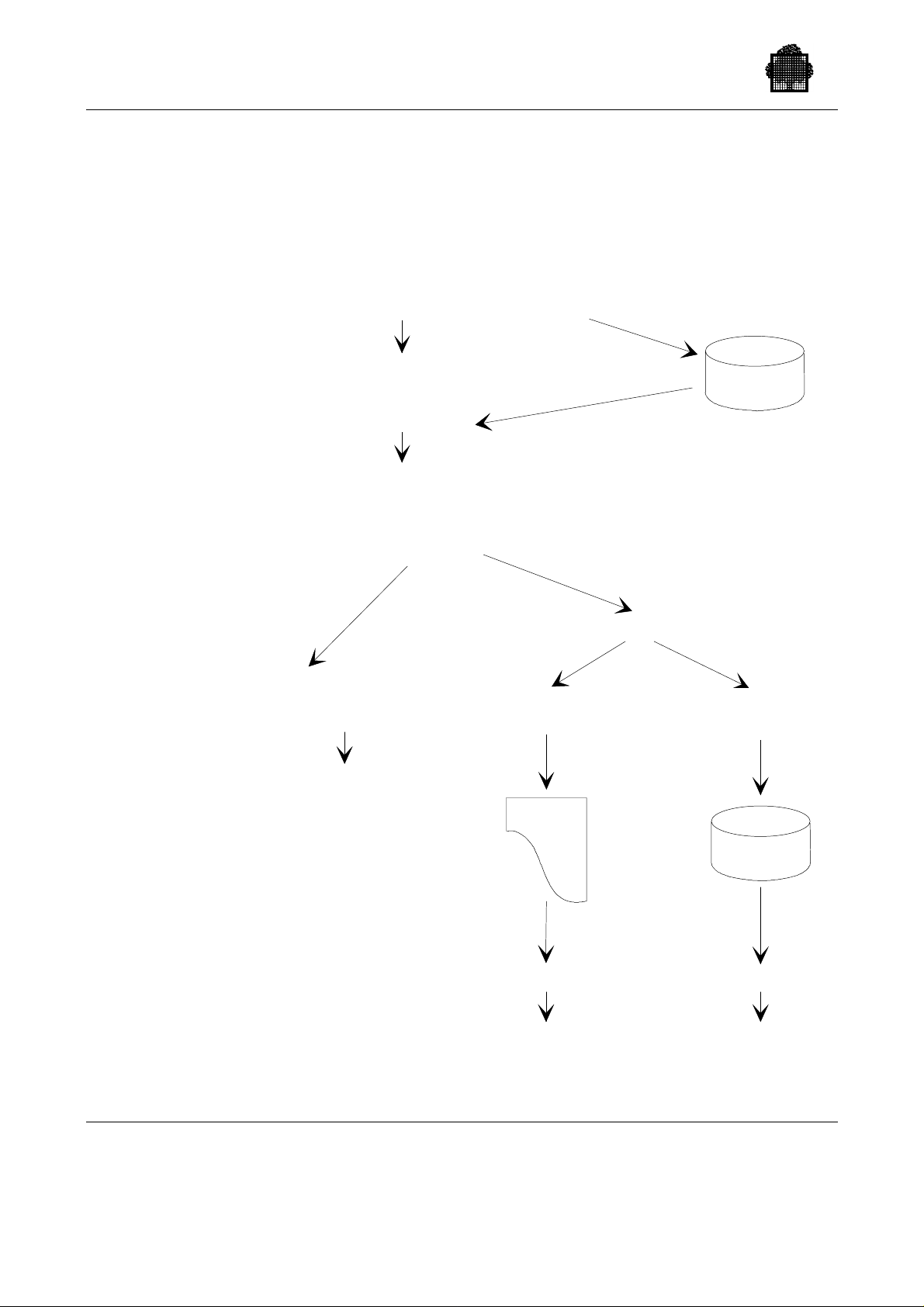
GCOS 7 System Operator’s Guide
4. SYNOPSIS OF FUNCTIONS RELATED TO DUMP
.
.
.
SYSTEM PREVIOUS STATUS ON ...
*IL01 OPTIONS ? DUMP_CD ( [A,] answer IL03,...)
IL01
*IL01 OPTIONS ? DUMP (DISK)
IL01
*IL01 OPTIONS ? DUMP
DUMP (CONS)
IL03 DUMP ?
IL28 WARNING
NO PREVIOUS DUMP IL14 CRASH COMMENTS ?
I:
IL01
M
IL03 answer
0, [efn:] volnm,DEF
EXEC,DPS_STD
SYS.
SYSDUMP
IL03
IL01
IL03
IL01
3-26 47 A2 53US Rev03
Page 99

3.4.3.6 DUMP_CD
[ {A} ]
DUMP_CD([ ];IL03 answer;[IL03 answer;]...)
[{APPEND}]
This option is used to record on disk the answers to the IL03 DUMP question
(DUMP s ession) . Th ese recorded answers will be used when answ ering
DUMP(DISK) to the IL01 question (refer to Section 3.4.3.5 DUMP).
When A or APPEND is used, t he an swers are append ed t o those already existing.
If th e last recorded answer is n ot "END ", the IL 03 qu es tion is disp layed again at
the console when DUMP(DISK) is used.
NOTE:
Starting and Terminating a GCOS 7 Session
This optio n does n ot crea te a library member. C onsequentl y, it is not possible to
update the DUMP_CD information with the maintain library processor.
3.4.3.7 HA (High Availability)
{ ON }
HA ({ } )
{ OFF }
This option is for management of the High Availability product. When ON is
entered, the Complex Management Service (CMSC) is started at GCOS 7
initialization. The default is ON.
47 A2 53US Rev03 3-27
Page 100

GCOS 7 System Operator’s Guide
3.4.3.8 HELP (or ?)
HELP (or ?)
This optio n (whe n type d first as a reply to the IL 01 or the IL03 qu es tion) displays a
HELP text with all possible replies to the *IL01 OPTIONS? and *IL03 DUMP?
questio ns on a main c onsole.
When the HELP text to the *ILO3 DUMP? question is displayed, the directive
MORE (Y/N)
app ears. If "Y" is entered, additional HELP t ex t wil l be displayed. If "N" is
entered, the display terminates.
The HELP text may be directed to the line printer by using the form:
HELP(PRINTER)
The *I L01 OPTI ONS? questi on is then displa yed again.
This option cannot be used on a library member.
3.4.3.9 INIT
[ {NAUTO} {NSILENT} ]
INIT[( { } { } ) ]
[ {AUTO } {SILENT } ]
This optio n specifi es the processin g of the n ex t, a nd subseque nt GCO S 7
initializations. When the AUTO parameter is entered, the next GCOS 7
initialization automatically uses the ISL options stored on disk.
Thes e options are stored in t wo members of the S YS.HSLLIB libra ry, or two
members of the lib rary spec ified by th e D I SK option. Depe nding on wheth er or not
there has been a firmware reinitialization, the options are read from different
library members:
• When the GCOS 7 reload is preced e d by a firmwar e reinitializ ation, the op tions
are read from the INIT_OPTIONS member.
• When there is no firmware reinitialization preceding the GCOS 7 reload, the
options are read from the RELOAD_OPTIONS member.
3-28 47 A2 53US Rev03
 Loading...