

Page 1
Aabenraavej 13-17, DK - 6340 Krusaa, Denmark
Tel: +45 74 62 20 88
Fax +45 74 62 74 07
E-mail: [email protected]
– Internet: www.bukh.dk
Publ. No.
009W2329
Work shop Manual
for
BUKH diesel engine
TYPE DV36/48
009W2329-R01
Page 2

Contents
Section A … Introduction and technical data
Section B … List of tools
Section C … Cylinder head
Section D … Flywheel
Section E … Front end cover
Section G … Rear end cover and hand start
Section H … Fuel system
Section IJ … Piston, connecting rod and cylinder liner
Section L … Crankcase, crankshaft, main bearings and oil sump
Section M … Camshaft
Section N … Lubricating oil system
Section O … Cooling water system
Section P … Electrical system
Section R … Gearbox ZF, BW7
Section S … Sail drive
Section T … Irregularities in operation - causes and remedies
Section V … Maintenance
009W2329-R01
Page 3

A1
SECTION A
INTRODUCTION AND TECHNICAL DATA
009W2329
Page 4

A2
CONTENTS
Introduction ................................................................................ page A 3
Technical Data ........................................................................... page A 4
Torques ..................................................................................... page A 5
Spare Part Nos. for Service Parts .............................................. page A 6
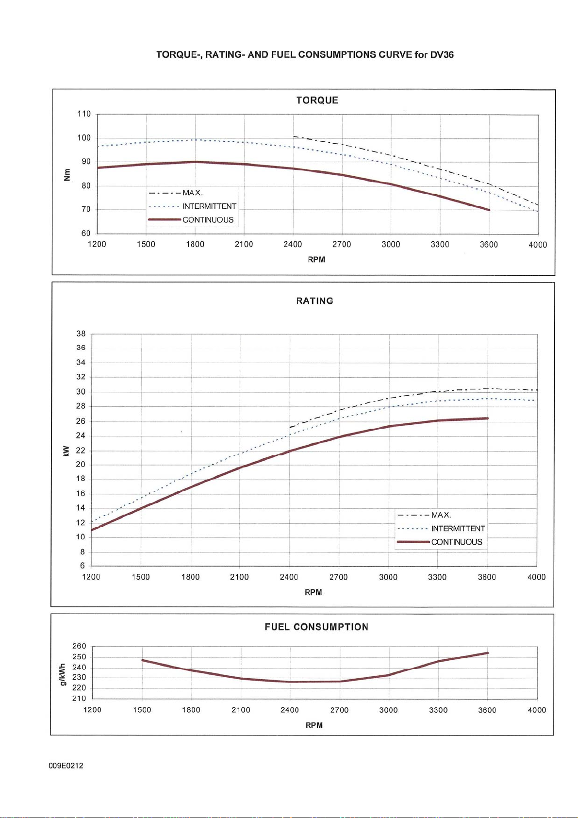
Torque and Rating Curves ......................................................... page A 7
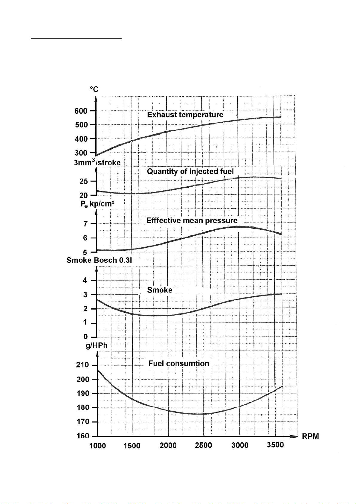
Results of Measurement ............................................................ page A 8
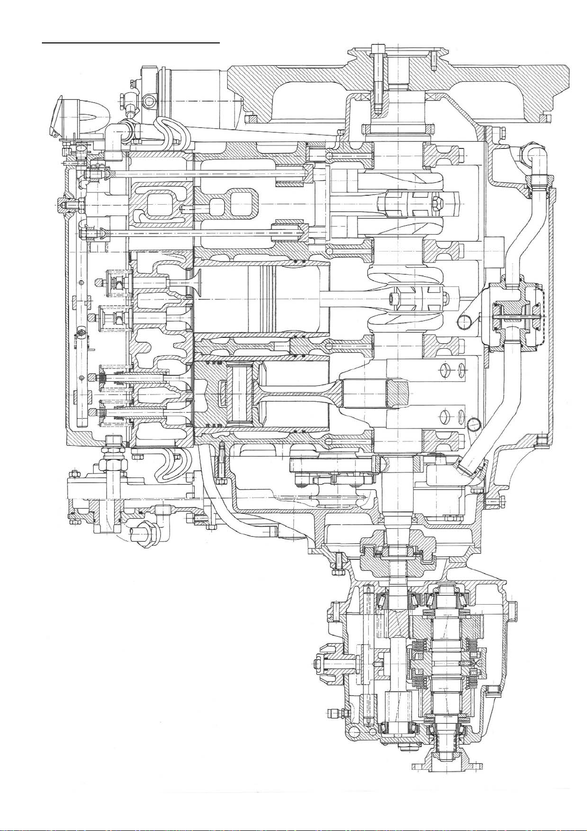
Longitudinal Section of DV36 .................................................... page A 9
Cross Section of DV36 .............................................................. page A 10
Diagram of the Relation between the Total Weight,
Speed and Horse Power of the Boat ......................................... page A 11
009W2329
Page 5

A3
Introduction
BUKH DV36 is a 3-cylinder, water cooled, 4-stroke diesel engine with direct injection, giving
an easy start at low temperatures, a low consumption of fuel and a low thermic load of the
cylinder head.
The engines are specially designed to comply with the heavy demands made on stability,
safety and environment now.
The technical structure of the engine with components and systems appears from the
individual sections of this workshop manual and therefore this introduction contains no
descriptions of this.
DV36 is designed with small installation dimensions compared to corresponding engine
outputs on the market. This applies to both height, length and width. At the same time the
weight of the engine is comparatively low and the proportion weight/horse power is in fact only
7.36 compared to corresponding engine outputs on the market with a corresponding factor of
8.28 and 8.48.
Being a 3-cylinder engine, DV36 is a naturally low level of vibration compared to 1- and 2-
cylinder engines, but in order to obtain a further improvement of the vibration level, the rotating
weight system has been continued on DV36 as it is known with great success from DV10 and
DV20. DV36 with the anti-vibration system is thus free from unpleasant vibrations and may
correctly be described as the less vibrating engine on the market.
DV36 is supplied either with sail-drive (type DV36SME) or with BW7 gear (type DV36ME). The
type description S = saildrive, M = marine gear and E = with electric start.
The temperature of the exhaust gas is for DV36 max. 550°C, which is about 100°C below
corresponding engine outputs on the market.
DV36 is delivered as standard with direct seawater cooling but may be alternatively be
delivered with heat exchanger built integral with water cooled exhaust, keel cooler or radiator
cooler.
009W2329
Page 6

A4
TECHNICAL MAIN DATA
WORKING PRINCIPLE……………………………………………………… ... 4-STROKE
BORE/STROKE ...................... ................................ ................................... 85 mm / 85 mm
CYLINDER VOLUME ............. ................................ ................................... 1.447 Litres
COMPRESSION RATIO ......... ................................ ................................... 18,5:1
COMPRESSION PRESSURE …. ................. at 1800-3600 rpm………… .. 46 Bar
OUTPUT, CONTINOUS RATING.…. ............ at 2400 rpm………..……… .. 29.8 BHP - 21.9 kW
ACCORDING TO ISO 3046……. .................. at 3000 rpm…………………..34.5 BHP – 25.4 kW
.............. at 3600 rpm…………………. 36.0 BHP - 26.5 kW
OUTPUT, INTERMITENT RATING BHP ....... at 4000 rpm ......................... 39.3 BHP – 28.9 kW
MAX. TORQUE Kp*m ............. ...................... at 1800 rpm .......................... 9.2 Kpm – 90 Nm
MAX. AIR CONSUMPTION .... ................................ ................................... 2214 Litres/min.
ENGINE ROTATING, LOOKING AT FLYWHEEL .. ................................... CLOCWISE
IDLING SPEED ....................... ................................ ................................... 800 – 1000 RPM
MAX INCLINATION, FORE AND AFT ..................... ................................... 15
HEEL, MAX. CONTINOUS ..... ................................ ................................... 30
NET WEIGHT INCL. ZF MARINEGEAR ................. ................................... 265 Kg
NET WEIGHT INCL. SAILDRIVE ............................ ................................... 290 Kg
LOCATION OF ENGINE SERIAL NUMBER ........... ................................... ON CRANKCASE NEAR FUEL THE PUMP
EXHAUST TEMP. MAX / NORMAL ......................... ................................... 600
VALVE TIMING AND INJECTION POINT
FLYWHEEL DIAMETER ......... ................................ ................................... 370 mm
INLET VALVE OPENS .................. BEFORE TDC . ................................... 32
INLET VALVE CLOSES ............... AFTER BDC .... ................................... 64
EXHAUST VALVE OPENS ............ BEFORE BDC . ................................... 64
EXHAUST VALVE CLOSES ......... AFTER TDC .... ................................... 32
INJECTION STARTS……… .......... BEFORE TDC……………………… ..... 6.2
VALVE CLEARANCES (COLD ENGINE) INLET/EXHAUST ...................... 0.30 mm
FUEL SYSTEM ...................... ................................ ................................... DIRECT INJECTION
INJECTOR OPENING PRESSURE ........................ ................................... 210 Bar
INJECTION TIMING .............. ................................ ................................... AUTOMATI C VARIABLE
FUEL LIFT PUMP ................... ................................ ................................... CAM SHAFT DRIVEN DIAPHRAGM PUMP
STATIC PRESSURE OF FUEL LIFT PUMP ........... ................................... 153 - 285 mBar
FUEL FILTER ......................... ................................ ................................... THROW AWAY FILTER INSERT
FUEL QUALITY GAS OIL ....... ................................ ................................... BS 2869 CLASS A
LUBRICATING SYSTEM
TYPE OF LUBRICATING OIL PUMP ...................... ................................... ROTARY VANE PUMP
LUBRICATING OIL PRESSURE: WARM ENGINE / MINIMUM ................. 2-4.5 Bar / 1 Bar
LUBRICATING OIL QUALITY ................................ ................................... SERVICE CC or CD
LUBRICATING OIL VISCOSITY .... BELOW +5
BETWEEN +5
ABOVE +25
o
C ...................................... SAE 10 or SAE 10W-30
o
c and +25oC ................ SAE 20 or SAE 15W-40
o
C . ................................... SAE 30 or SAE 15W-40
LUBRICATING OIL CONTENT INCL. FILTER ........ ................................... 4.9 Litres
LUBRICATING OIL FILTER .. ................................ ................................... THROW AWAY FILTER INSERT
ZF BW7 MARINEGEAR
LUBRICATING OIL QUALITY ................................ ................................... API CC or CD, MILL-L-46152
LUBRICATING OIL VISCOSITY .............................. ................................... SAE 30 or SAE 15W-40
LUBRICATING OIL TEMPERATURE...................... ................................... MAX. 120
LUBRICATING OIL CONTENT ............................... ................................... 1.1 Litres
NEWAGE PRM120 MARINEGEAR
LUBRICATING OIL QUALITY ................................ ...................................
LUBRICATING OIL TEMPERATURE...................... ................................... MAX. 120
LUBRICATING OIL CONTENT ............................... ................................... 0.8 Litres
o
o
o
C – 580oC
o
(arc measure: 103 mm)
o
(arc measure: 207 mm)
o
(arc measure: 207 mm)
o
(arc measure: 103 mm)
o
(arc measure: 20 mm)
o
C
Automatic Transmission Fluid (ATF)
o
C
009W2329
Page 7

A5
BAYSAN M60 MARINEGEAR
LUBRICATING OIL QUALITY ................................ ...................................
LUBRICATING OIL TEMPERATURE...................... ................................... MAX. 120
LUBRICATING OIL CONTENT ............................... ................................... 0.5 Litres
STERN TUBE (FLEXIBLE) LUBRICANT ................ ................................... OUTBOARD GEAR OIL
COOLING WATER SYSTEM – DIRECT SEAWATER COOLING
COOLING WATER TEMPERATURE ...................... ................................... 50 – 65
TYPE OF CIRCULATING PUMP / CAPACITY AT 3600 rpm ..................... CENTRIFUGAL / 24-30 Litres/min
CAM HEIGHT ......................... ................................ ................................... 2.0 mm
MAX. PUMP COUNTER PRESSURE ..................... ................................... 0.6 Bar
MAX. PUMP SUCTION PRESSURE....................... ................................... 0.3 Bar
COOLING WATER SYSTEM – INDIRECT COOLING WITH FRESHWATER
COOLING WATER TEMPERATURE ...................... ................................... 70 – 95
TYPE OF FRESHWATER PUMP / CAPACITY AT 3600 rpm ..................... CENTRIFUGAL / 135 Litres/min
PUMP PRESSURE ................. ................................ ................................... 1.1 Bar
TYPE OF SEAWTAER PUMP / CAPACITY AT 3600 rpm .......................... CENTRIFUGAL / 36-42 Litres/min
CAM HEIGHT ......................... ................................ ................................... 3.1 mm
MAX. PUMP COUNTER PRESSURE ..................... ................................... 0.6 Bar
MAX. PUMP SUCTION PRESSURE....................... ................................... 0.3 Bar
ELECTRICAL SYSTEM
BATTERY VOLTAGE / CAPACITY ............................................................ 12 VOLT / 88 Ah
STARTER TYPE / OUTPUT ....................................................................... GEAR DRIVEN / 1.0 KW
ALTERNATOR TYPE/ OUTPUT ................................................................ BELT DRIVEN / 700 W
ENGINE STOP ........................................................................................... SOLONOID / MANUAL
RELAY ........................................................................................................ EL ECTRONIC, BUILT ON
TORQUES
CYLINDER HEAD BOLTS/BEARING TOP SECTION ................................ 118 +/- 5 Nm (12 +/- 0.5 Kpm)
CONNECTING ROD BOLTS . .................................................................... 69 +/- 3 Nm (7 +/- 0.3 Kpm)
FLYWHEEL/COUNTERWEIGHTS ... .......................................................... 147 +/- 7 Nm (15 +/- 0.7 Kpm)
FLEX. COUPLING .................. .................................................................... 61 +/- 3 Nm (6.3 +/- 0.3 Kpm)
ASSEMBLY OF FUEL VALVE .................................................................... 59 +/- 3 Nm (6.0 +/- 0.3 Kpm)
BRACKET FOR ENGINE SUPPORTS ....................................................... 69 +/- 3 Nm (7 +/- 0.3 Kpm)
GEARBOX .............................. .................................................................... 25 +/- 5 Nm (2.5 +/- 0.5 Kpm)
Automatic Transmission Fluid (ATF)
o
C
o
C
o
C
009W2329
Page 8

A6
Spare Part Numbers for Service Parts
In this manual we have maintained on the drawings some numbers which are also spare part
numbers. However, this manual is not to be regarded as a spare parts catalogue but only as
helping guidance for correct identification of parts.
In the daily service work, some of the parts must be replaced after the number of hours stated
in the owner´s manual and in this book, and therefore we have made the following table:
610J0200 Lubricating oil filter
610D0201 Fuel filter
020D4326 Air filter
000E0450 Sacrificial zinc anode
610G0506 Impeller
542A0602 V-belt 10*1035 (seawater cooling)
542A0609 V-belt 10*1100 (freshwater cooling)
009W2329
Page 9
A7
009W2329
Page 10
A8
Results of Measurement
The below curves indicate results of measurements at 762 mm Hg and a room temperature of 26 °C.
009W2329
Page 11
A9
Longitudinal Section of DV36
009W2329
Page 12
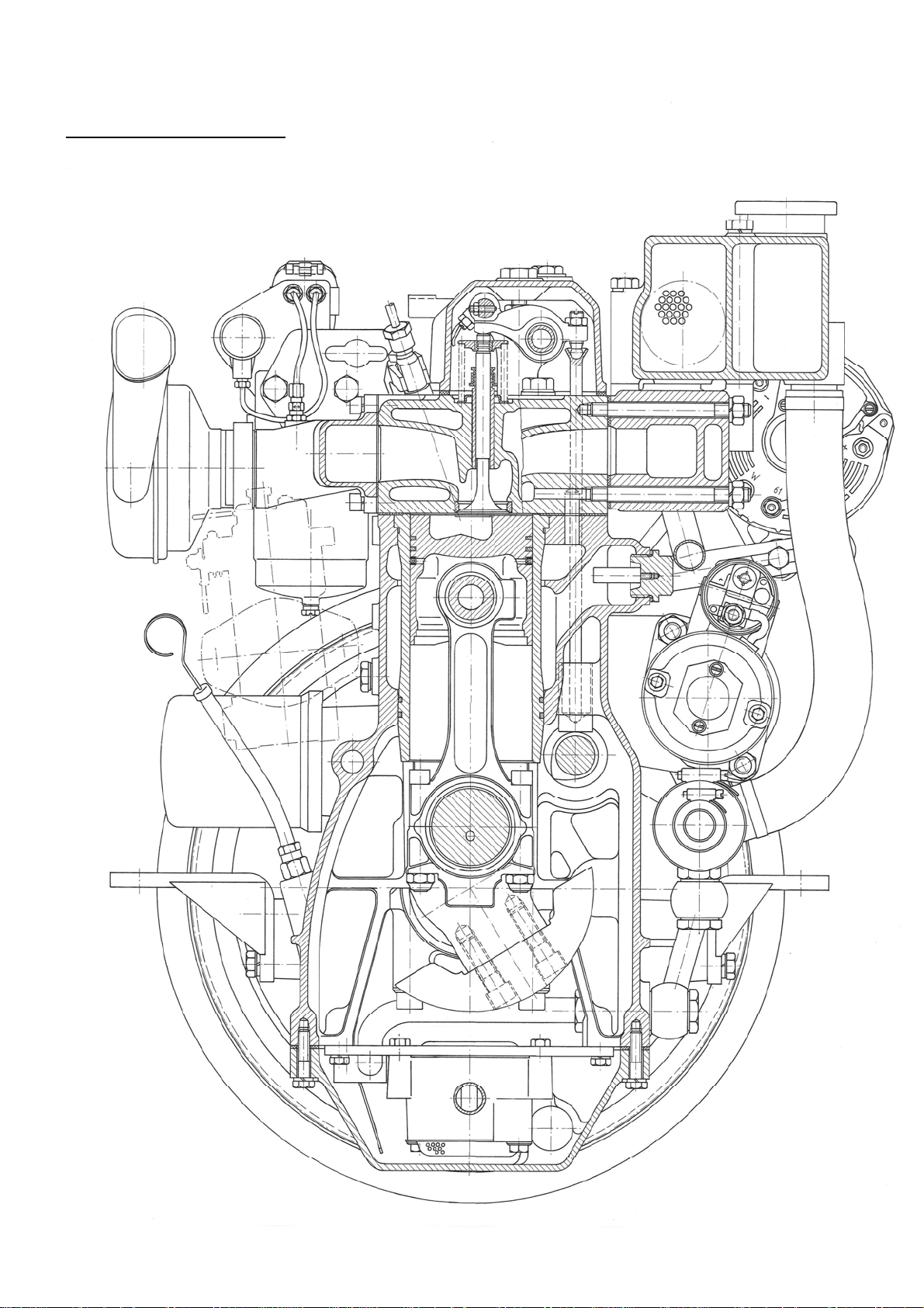
A10
Cross Section of DV36
009W2329
Page 13
A11
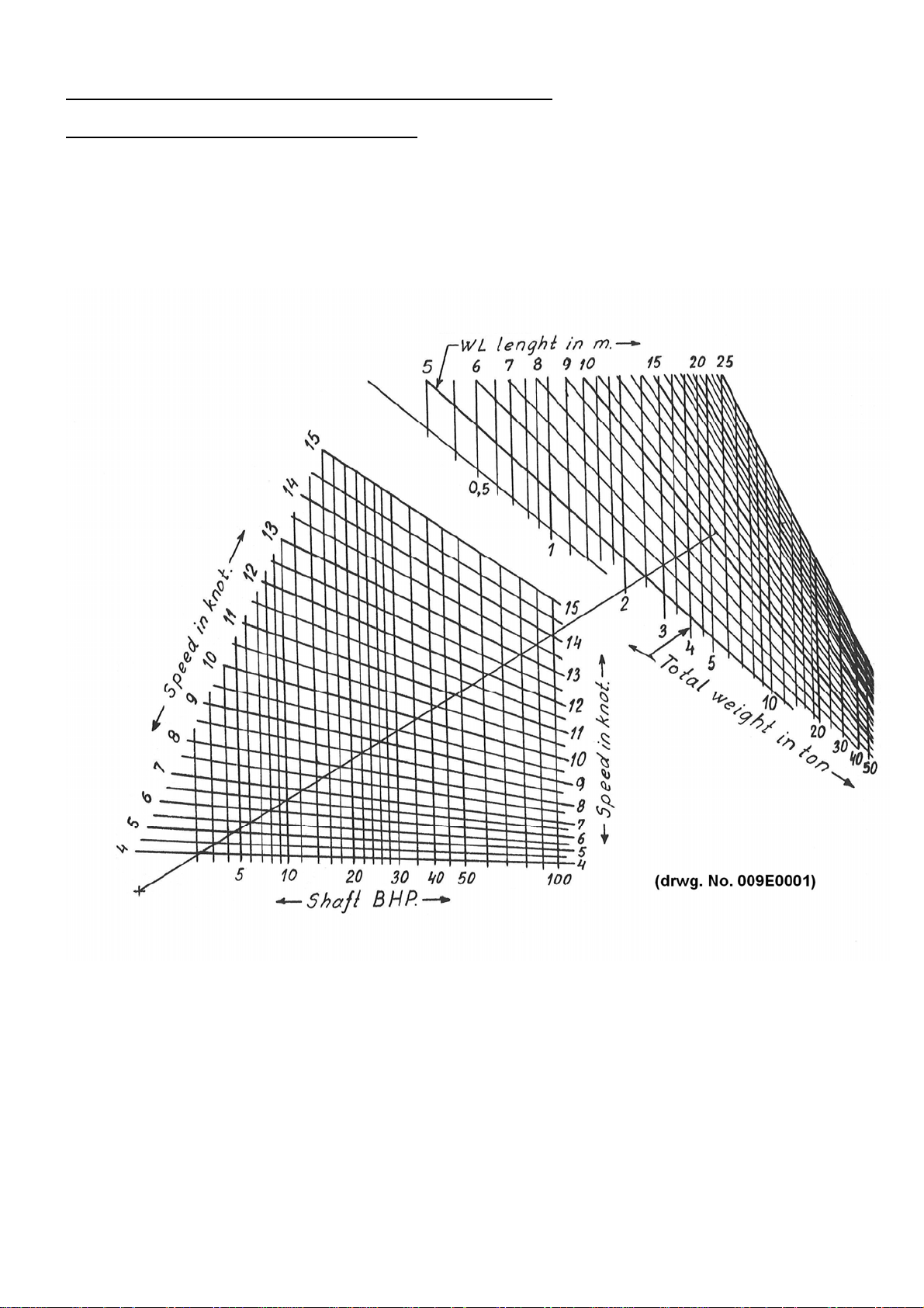
Diagram of the Relation between the Total Weight,
Speed and Horse Power of the boat
The below diagram is normative and not binding in any way as many different circumstances
influence the result, especially the type and shape of the boat, the propeller and its placing as
well as the horse power of the engine.
Seek the scheme to the right of the intersection between the actual length in the waterline of the
ship and the total weight.
Draw a straight line between this point (the intersection) and the fixed point in the bottom left corner.
Where the line of the desired speed crosses the straight line, you can read the required horse
power vertically below.
If you know three of the specifications, you can by means of these schemes find the fourth one.
009W2329
Page 14

Page 15

B1
SECTION B
LIST OF TOOLS
009W2329-R01
Page 16

B2
CONTENTS
Tools for repairs on DV36 .......................................................... page B 3
Dimensions of mounting punches ............................................. page B 6
009W2329-R01
Page 17
B3
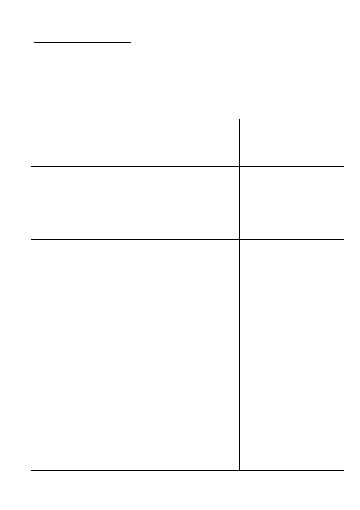
Tools for repairs on DV36
The below mentioned tools are necessary to make the engine repairs described in this
manual.
Part of the tools are special tools which can be ordered from the spare parts department at
BUKH.
We have indicated the fields of application for the special tools in this manual.
Designation of tools Fields of application Spare part No.
Slip-on ring for mounting of
pistons
Puller for cylinder liner
Punch for rear seal ring
Punch for front seal ring
Punch for mounting of
camshaft bearing in block
Punch for journal for
intermediate wheel
Punch for journal for front and
rear rotating weight
Section IJ
Section IJ
Section G
Section E
Section M and L
Section G
Section E and G
009P2235
009P3177
009P3178
009P3179
009P3180
009P3181
Punch for mounting of valve
Section C
009P3175
guide
Punch for mounting of inlet
Section C
009P3173
valve seat
Punch for mounting of exhaust
Section C
009P3174
valve seat
Punch for mounting of expan-
Section C
009P3176
sion discs in the cylinder head
009W2329-R01
Page 18

B4
Designation of tools Fields of application Spare part No.
36 mm socket spanner
19 mm socket spanner for
fastening of cylinder head
19 mm crowfoot wrench for
tightening up of cyl. head
10 mm Allen top for faste-ning of
bearing top section
5 mm Allen key
6 mm Allen key
7 mm Allen key
Section C
Section C
Section L
-
-
-
009P3225
Open-end spanner/ring spanner,
8/10/12/13/14/15/17/19/22/24/27
30 and 32 mm
Dismantling tool for valve
springs
Tachometer
Testing set for fuel nozzles
Cleaning for fuel nozzles
Bosch dial indicator for
adjustment of fuel pump
-
Section C
Generally
Section H
Section H
Section H
009P3115
009P3106
009P3100
009P3101
Bosch dial indicator “holder with
extension” for adjustment of the
fuel pump (KDEP1085)
009W2329-R01
Section H
529W0002
Page 19

B5
Designation of tools Fields of application Spare part No.
Flanging tools for nozzle holder
insert
Torque wrench
(Stahlwille 73/6 1.5-6.5)
Torque wrench
(Stahlwille 73/25 8-26)
Circlip tongs (external)
A1, 10-28 mm
Circlip tongs (internal)
J2, 19-75 mm
Puller for gear wheel
(Kukko 20/10)
Puller for flexible coupling
Section C
Generally
Generally Section C, D,
IJ and L
-
-
Generally
Section R
009P2565
009P3108
009P3109
T 41069
Compression gauge
Adapter for compression gauge
Section C
Section C
529W0000
009P3123
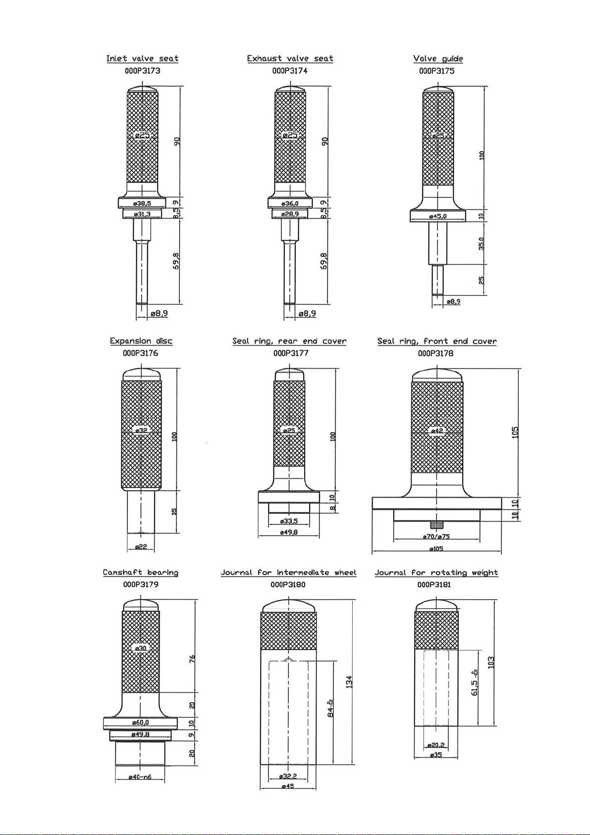
Part of the mentioned special tools can be manufactured without too much trouble at the
dealer´s workshopin periods outside the boat season. Therefore we have made sketches at
page B6 of each individual mounting punch with dimensions.
Slip-on ring for mounting of pistons is not illustrated but is manufactured of a worn out
cylinder liner or another piece of work pipe. Cut the cylinder liner so that you get a piece
being about 100 mm high, the turn it conical inside the liner or pipe.
009W2329-R01
Page 20
B6
009W2329-R01
Page 21

C1
SECTION C
CYLINDER HEAD
009W2329-R01
Page 22

C2
CONTENTS
Exploded view of cylinder head complete ................................. page C 3
Valve adjustment ...................................................................... page C 4
Removal and refitment of cylinder head ................................... page C 5
Replacement of rocker arm or rocker shaft .............................. page C 6
Adjustment of valve lifter arrangement ..................................... page C 6
Replacement of rocker arm bushing ......................................... page C 7
Removal of fuel valves ............................................................. page C 8
Nozzle holder insert .................................................................. page C 9
Fitting measures for fuel nozzle insert ...................................... page C 10
Valve springs ............................................................................. page C 11
Replacement of valve guides .................................................... page C 12
Pressing-in dimensions for valve guide ..................................... page C 13
Valve guide stuffing box ............................................................ page C 14
Repair or replacement of inlet and exhaust valves .................... page C 15
Exhaust valve ............................................................................ page C 16
Inlet valve .................................................................................. page C 17
Grinding of valves ...................................................................... page C 18
Measures for new valves ........................................................... page C 18
Replacement of valve seats ..................................................... page C 19
Cylinder head gasket ................................................................ page C 20
Air inlet manifold arrangement ................................................... page C 21
Exhaust manifold arrangement .................................................. page C 22
009W2329-R01
Page 23
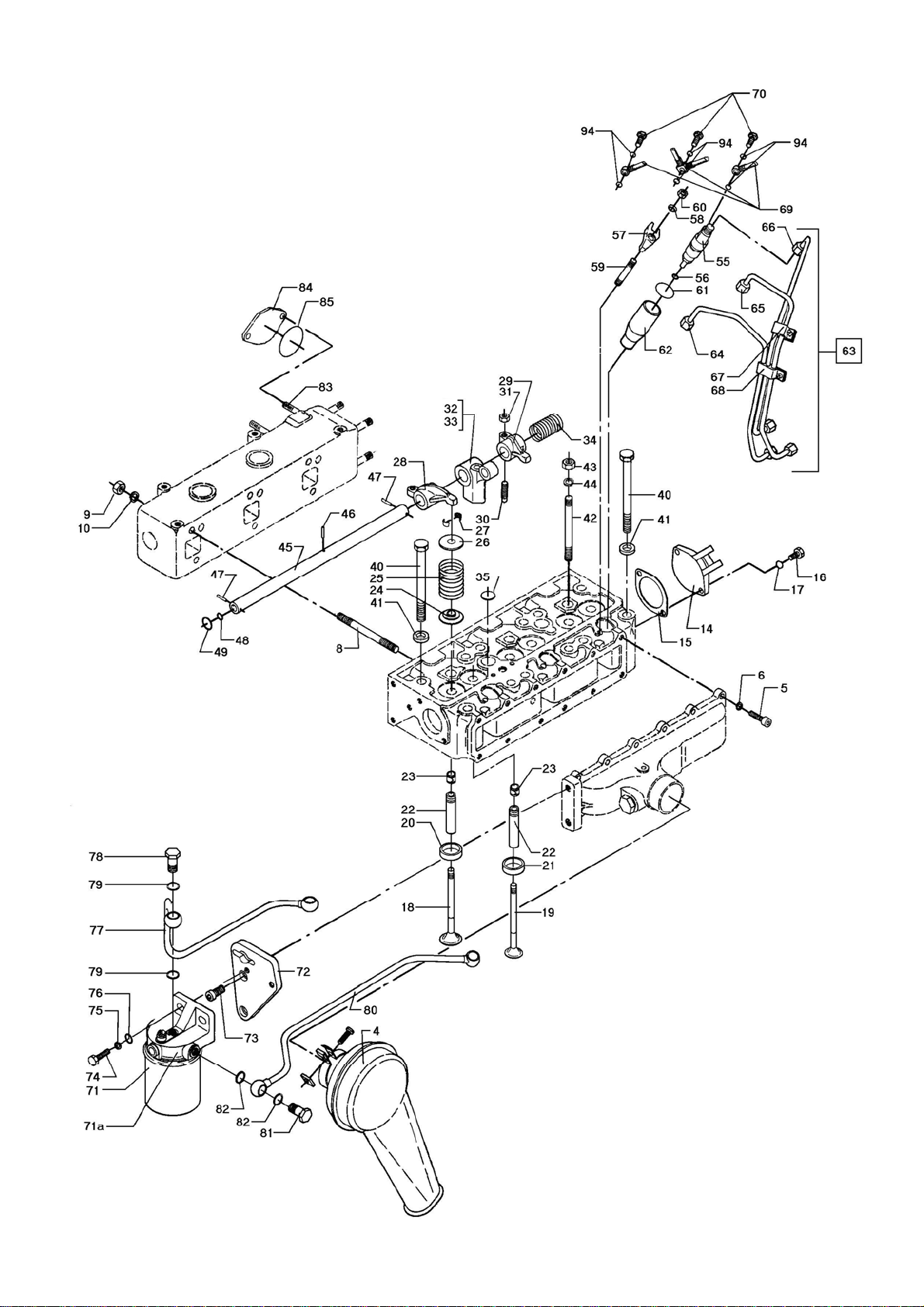
C3
Exploded view of cylinder head
009W2329-R01
Page 24
C4
Valve adjustment
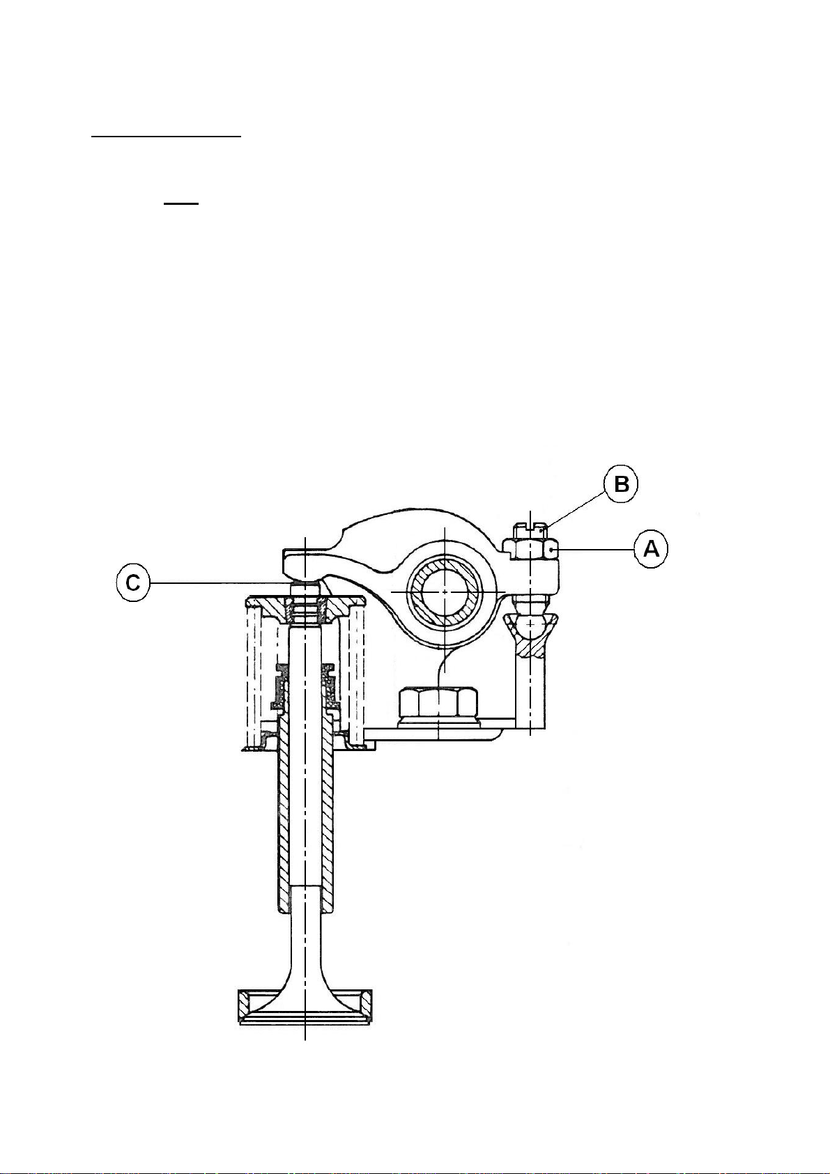
The clearance of the inlet and exha ust valves should be adjusted at 0.3 mm w hen the
engine is cold and the clearance of the valves should always be checked after tightening-
up of the c ylinder head. The valv es are adjusted when the pisto ns are alternately at their
highest point in the working stroke.
Adjust the valves by loosening the counter nut A which makes it possible to adjust the
clearance by means of the adjusting screw B.
Measure the clearance with a feeler gauge at C.
009W2329-R01
Page 25
C5
Removal and refitment of cylinder head
1. Drain off the cooling water.
2. Remove the top cover.
3. Remove valve rocker arms.
4. Remove the inlet and return pipes of the fuel valves.
5. Remove the charging alternator.
6. Remove the exhaust and inlet manifold.
7. Loosen the top bolts, after which the cylinder head can be lifted out of the engine block.
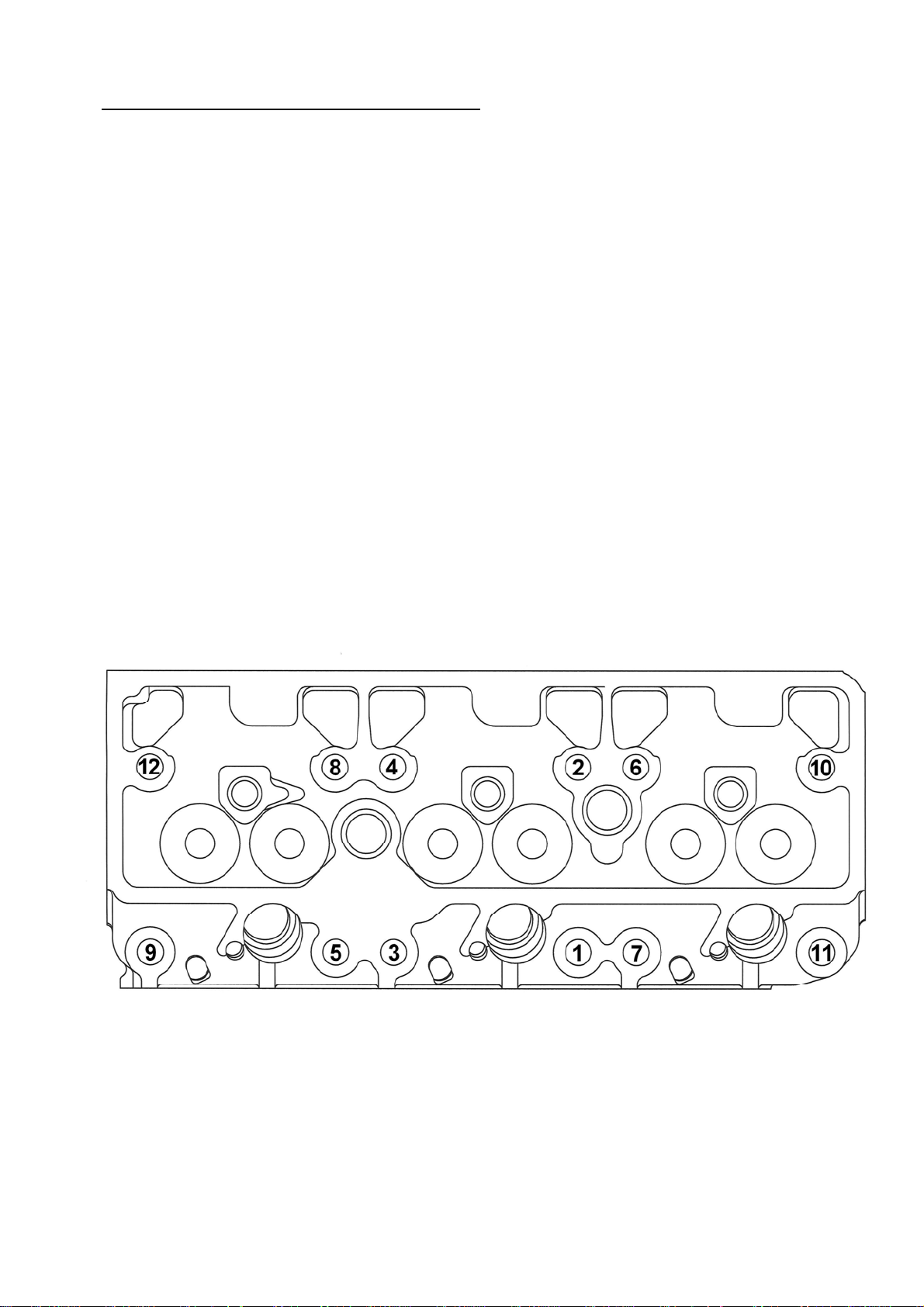
8. Refitment of the cylinder head is made in reverse order and the bolts are tightened
evenly at a torque of 118±5 Nm (12±0.5 kpm). Tighten in the order shown on the
skeleton diagram below.
009W2329-R01
Page 26
C6
Replacement of rocker arm or rocker shaft
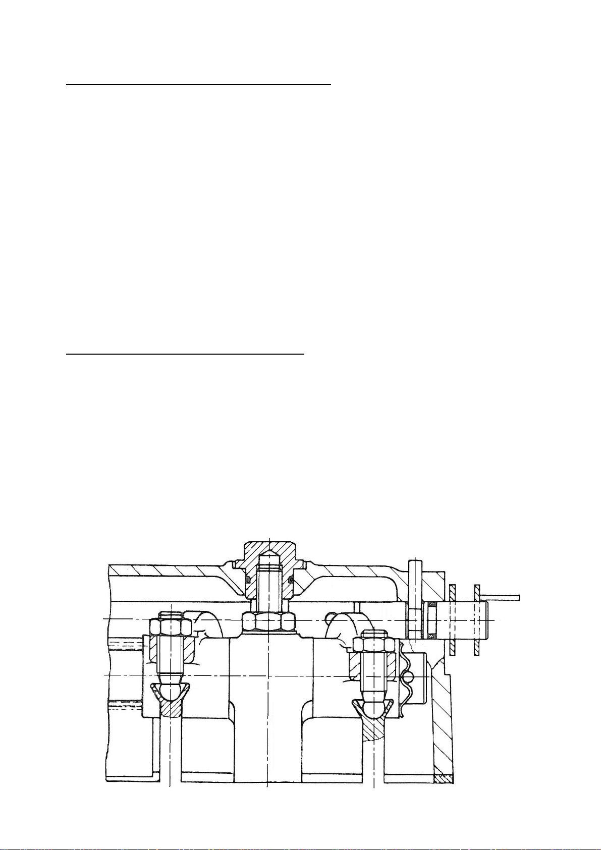
For each cylinder, a rocker arm column wit h two rocker arms for inlet valve and exhaust
valve, respectively, is fitted on a common shaft with corresponding rocker arm columns and
rocker arms for the two other cylinders.
1. Remove the top cover.
2. Unscrew the three central nuts on the rocker arm columns.
3. Lift off the shaft arrangement.
4. Knock out the tube pin and washer in one of the shaft ends.
5. Then the rocker arms and the intermediate springs can be taken out.
Reassembly is a reversal of the dismantling procedure.
Adjustment of valve lifter arrangement
Furthermore, a common shaft for decompression is fitted on the three rocker arm
columns.
For a possible removal of the shaft, remove first the pins going down on the rocker arms
at decompression, after which the shaft can be pulled out.
When adjusting, adjust the pins so that you faintly see a single groove of the pin thread
(about 1.5 mm free pin) just on the side facing the rocker arms.
When fitting the top cover, ensure that the slot in the decompression handle in the top
cover mesh with the corresponding pin on the decompression shaft.
009W2329-R01
Page 27
C7
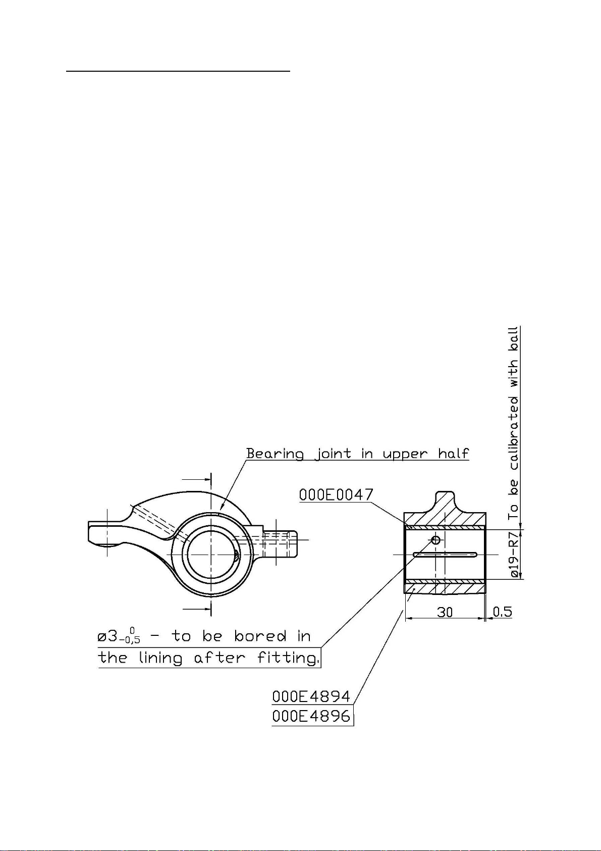
Replacement of rocker arm bushing
1. Remove the rocker arm as indicated on page C5 and check it as to wear and tear
as well as fracture.
2. Press out the defective bushing with an adequate tool.
3. Fit the new bushing as shown below paying special attention to the position of the
bearing joint and the oil grooves.
4. When fitted, calibrate the bearing bush so that the tolerance ø19-R7 is observed.
Do this either with a calibration ball or with a reamer having the mentioned tolerance.
5. After refitting the rocker arm, check the axial play with a feeler gauge. The axial
play may be 0.1 – 0.2 mm.
6. Finish refitting the rocker arm arrangement.
drwg. No. 008E4893
009W2329-R01
Page 28
C8
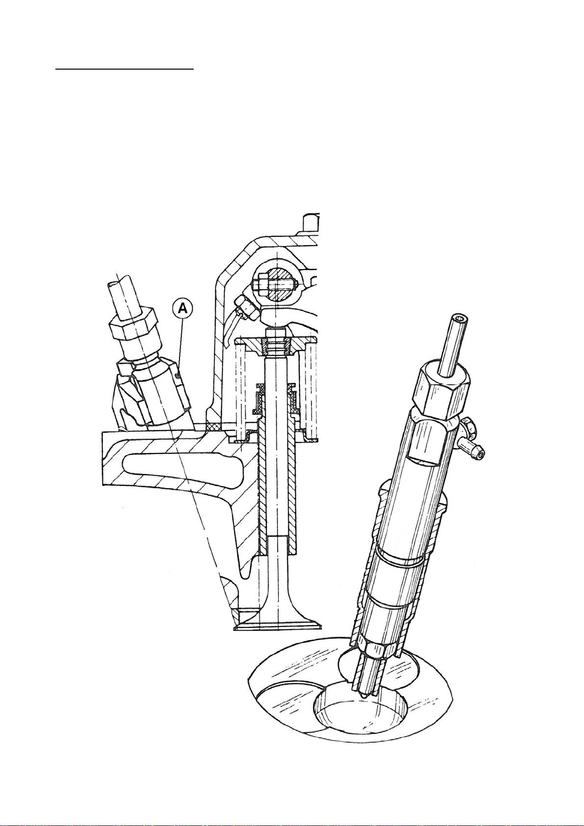
Removal of fuel valves
The fuel valves are removed by loosening the clamping nuts for the flanges A as indicated on
the sketch below after removal of the inlet and return pipes of the fuel valves.
The drawing at the bottom right-hand side indicates the placing of the fuel valve in proportion
to the piston.
For repair of the fuel valves, we refer to section H.
009W2329-R01
Page 29
C9
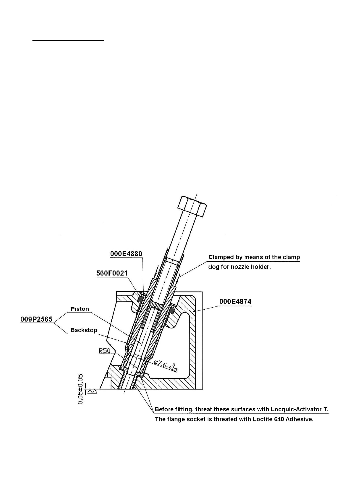
Nozzle holder insert
The nozzle holder inserts are placed in the cylinder head and form – a the name indicates –
an insert for the placing of the fuel valves in the cylinder head.
The nozzle holder ins erts can be replace d, which demands that the sp ecial tools below for
flanging (piston and backstop) are used and that t he surfaces are treated as indicated on the
drawing.
Remove the old nozz le holder inserts by bor ing-up the flanged end of the nozzle holder
inserts with a ø8 – ø9 mm drill, and then k nock out the nozzle h older inserts with a 10 mm
punch.
After having fitted the new nozz le holder insert s, test the cylinder head for pressure with
water in order to check the flanged seals.
drwg. No. 008E4881
009W2329-R01
Page 30
C10
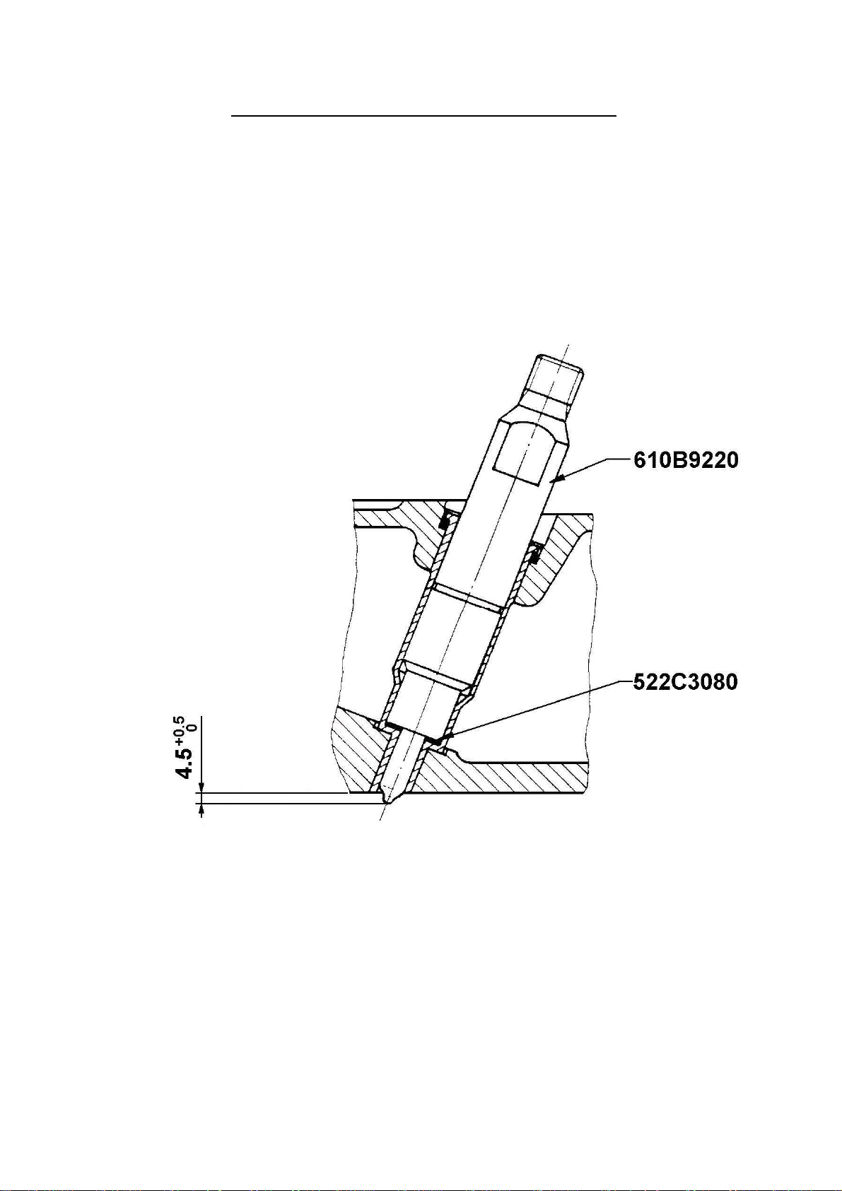
Fitting measurements for the fuel nozzle into insert.
009W2329-R01
Page 31
C11
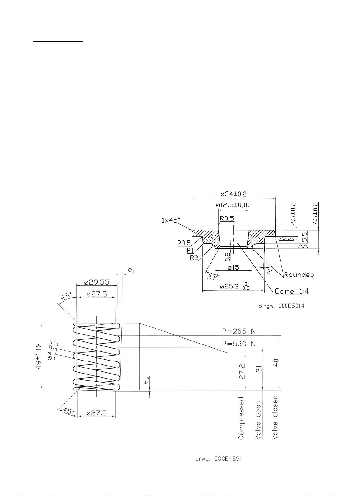
Valve springs
Six identical springs for inlet and exhaust valves, respectively, are fitted in the cylinder head.
The springs are identical in both ends, and therefore fitting up or down is of no importance.
The springs are locked in their position in proportion to the valve stems by means of two
conical halves for each valve spring and guided by a guide for valve spring and a
corresponding disc, respectively.
The valve springs are removed by compressi ng the valve springs and removing the c onical
locking halves with s pecial tools or the like so the valves are cut off fro m following the
movement of the springs.
When refitting the valve springs, make sure t hat the conical loc king halves are correctly
placed in their trace on the va lve stems. This can be done by knocking gently with a plastic
hammer on top of the valve stem while the cylinde r head is lifted from the file bench so that
the valve heads can move so as to be clear of the valve seats.
009W2329-R01
Page 32
C12
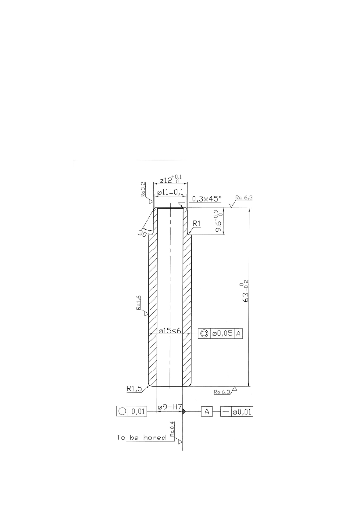
Replacement of valve guides
Replace the valve guides whic h are pressed into the cylinder head if the tolerance is
exceeded because of wear and tear by 0.05 mm. Check the measure with a ø9 – H7 internal
gauge according to the drawing below of the valve guide.
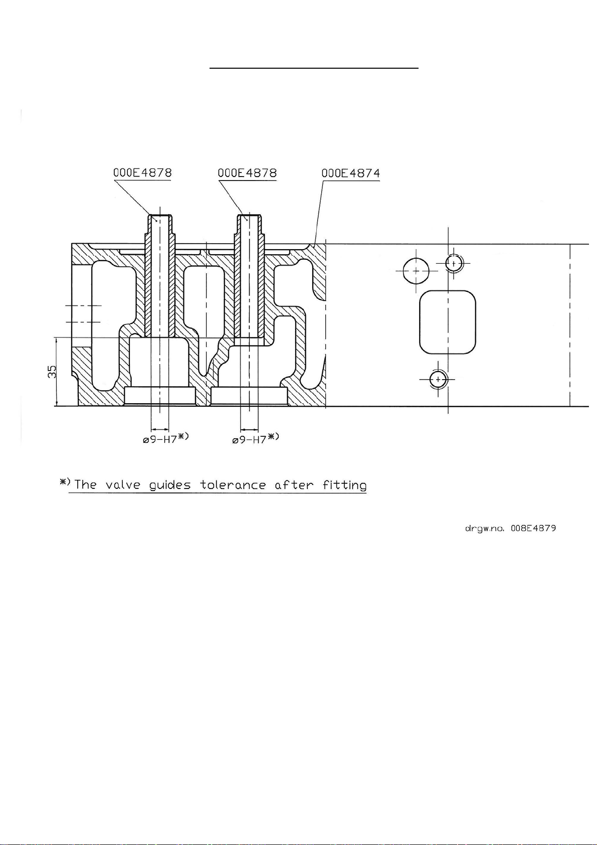
Fit new valve guides according to the drawing on page C13. Before fitment, heat the cylinder
head in an oven or heat it in boiling water and cool down t he valve guides in a deep freezer
or otherwise.
After fitment of new valve guides, broach the bore of the valve guides with a broach in order to
remove possible ups ettings from the fitti ng. Use a broach ø 9 – H7 for the broaching.
009W2329-R01
Page 33
C13
Pressing-in dimensions for valve guide.
009W2329-R01
Page 34
C14
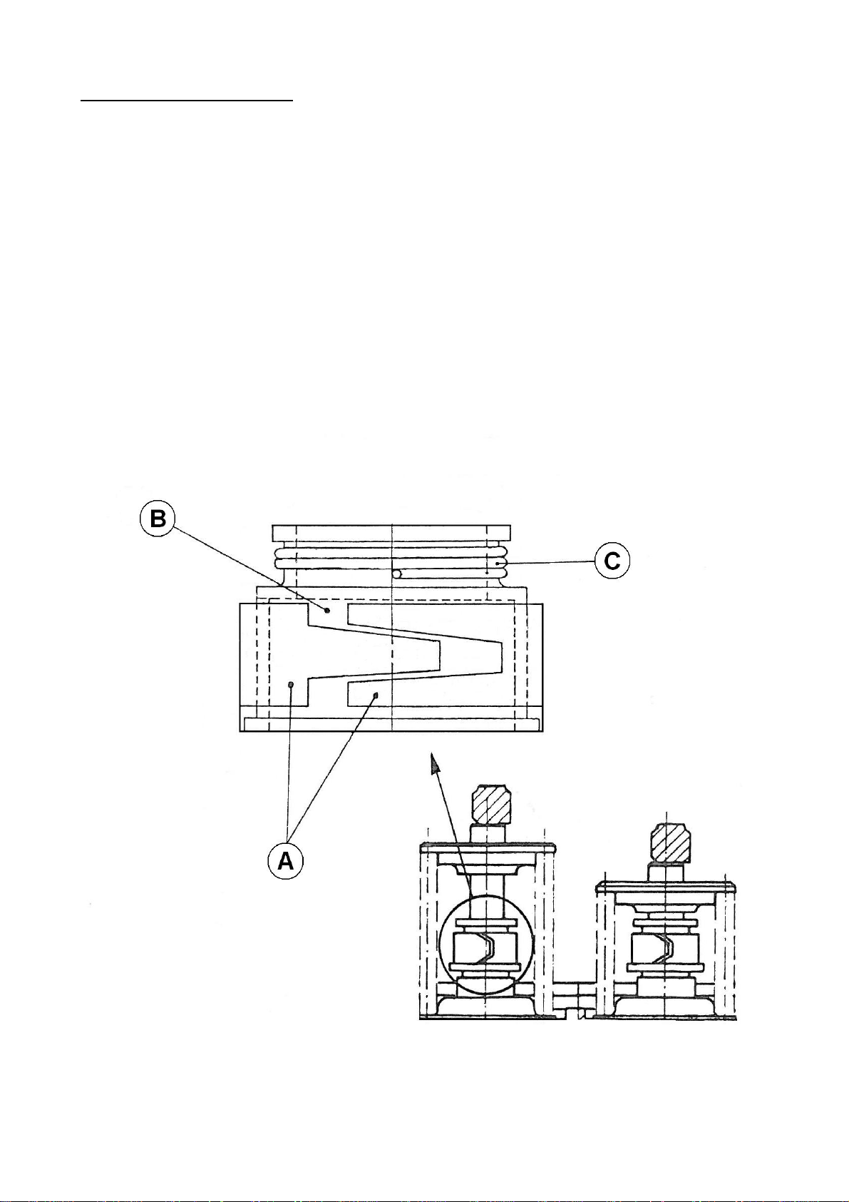
Valve guide stuffing box
In order to avoid lubricating oil consumption because of lubricating oil passing between valve
guide and valve stem causing the valves to be burnt or to be carbonized, a stuffing box has
been mounted on the upper end of the valve guides.
The stuffing box is as shown schematically on the drawing below and consists of:
A: Metal spring coat
B: Plastic bushing
C: Spring wire
The stuffing box compensates for wear and tear of the valve guides so that the lubricating oil
consumption because of leaky valve guides is reduced to a minimum.
The stuffing box cannot be repaired but has to be replaced if necessary.
009W2329-R01
Page 35

C15
Repair or replacement of inlet and exhaust valves
1. Remove the cylinder head from the engine (page C5).
2. Then place the cylinder head on a file bench or the
like with the valve seats at the bottom.
3. Compress the valve springs with a special tool or the
like and remove the conical valve locking halves.
4. Then place the cylinder head upright and remove the
valves from the cylinder head.
Refitment is a reversal of removal procedure.
Note! Refit the valves in the same valve guides again.
Replace the valves if they are so damaged that a refacing with special tools and subsequent
grinding are impossible without exceeding the tolerances indicated on page C18 and C19.
A refacing of the valve seats with fixed guide should always be made if the valve does not
function satisfactorily.
After replacement of valve or valve seat, grind together with abrasive compound seat and valve
so that total tightness is obtained. It is an indispensable condition for the compression of the
engine that this work is performed carefully.
Grinding of valves is made as described on page C18.
009W2329-R01
Page 36
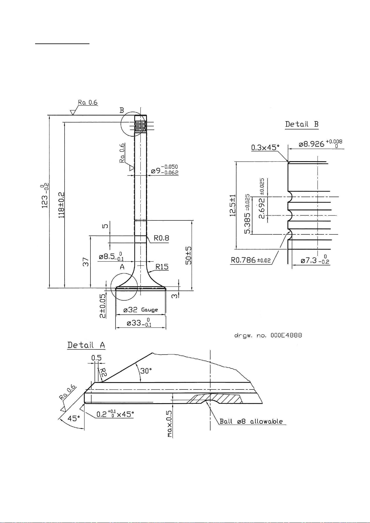
C16
Exhaust valve
Tolerances and repair measures.
009W2329-R01
Page 37
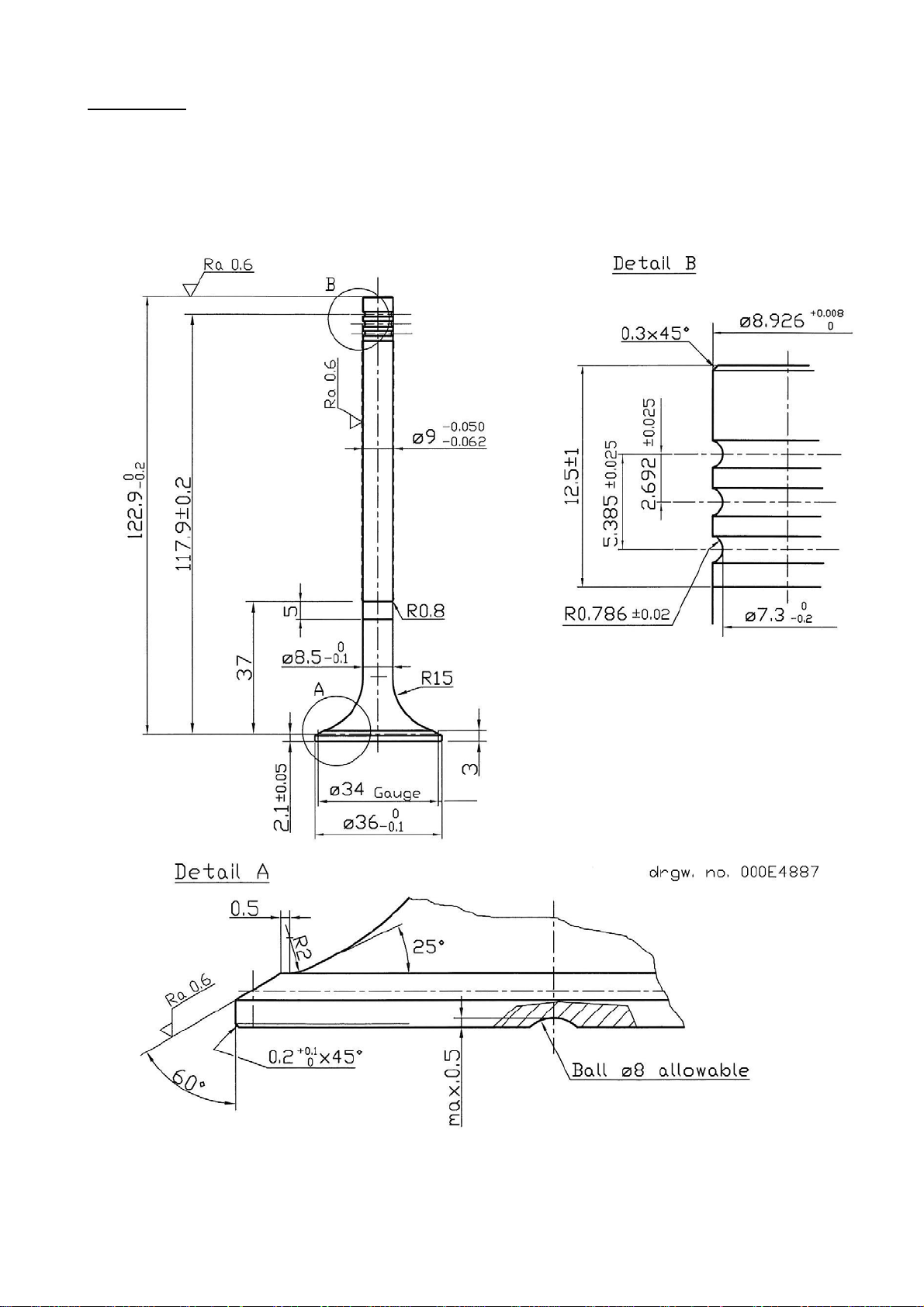
C17
Inlet valve
Tolerances and repair measures.
009W2329-R01
Page 38
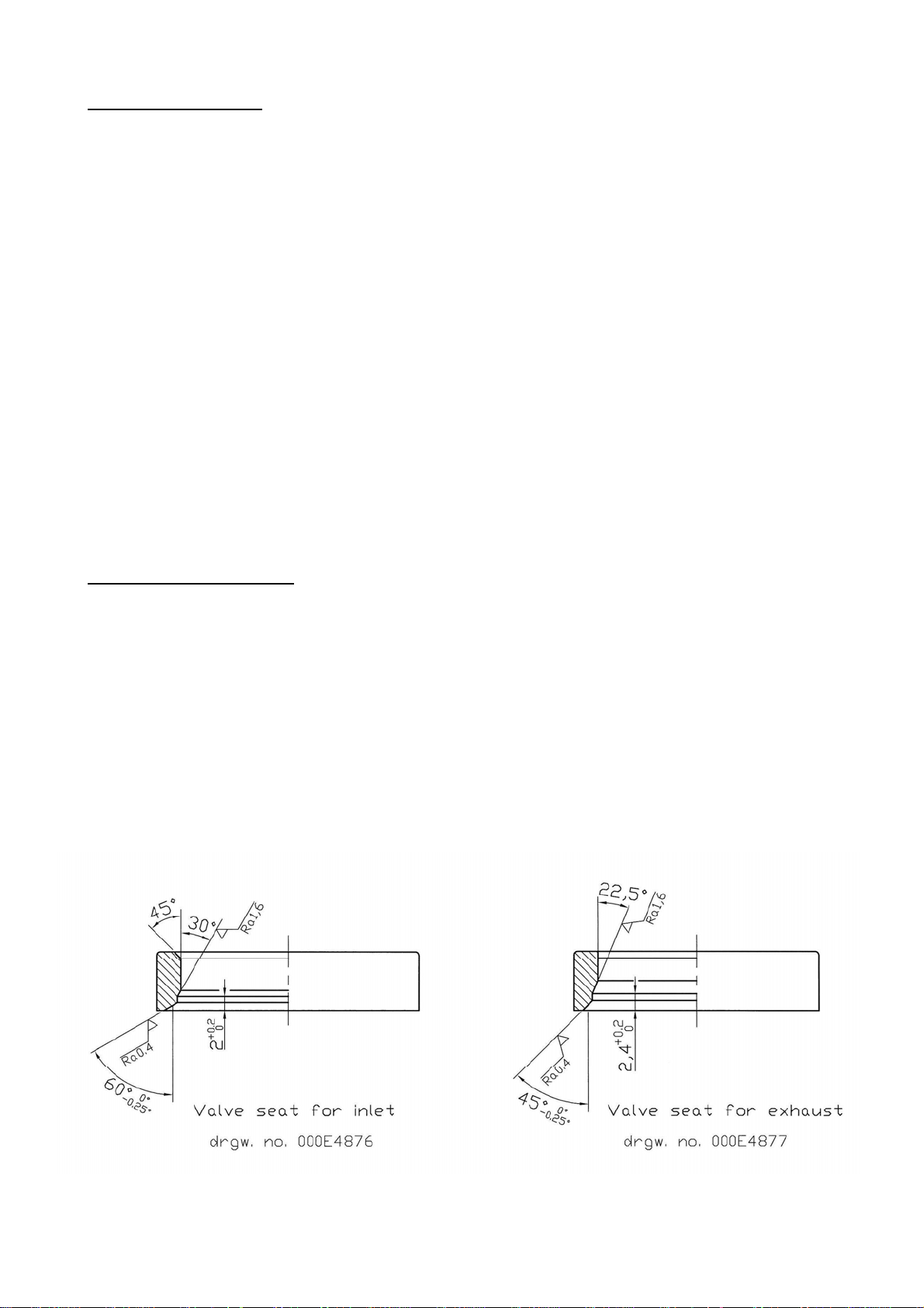
C18
Grinding of valves
1. Place the cylinder head with the valve seats upwards. Block the cylinder head so that
the valves fit tightly against the seats and can be turned freely by means of a rubber
suction disc or the like.
2. Apply abrasive compound to valve and seat, after w hich grinding can tak e place.
3. When grinding, turn the valve by means of the rubber suction disc in various directions
while fitting it at the same time with an equal pressure against the seat. When
grinding, lift frequently the valve and spread all over the seat the abrasive c ompound
applied.
4. You can c heck whether the valve is ti ght by cleaning off the abrasive compound
carefully by for exam ple cleaning liquid. Then make 4 pencil m arks staggered 90
degrees from each ot her on the c ontact face of the valve. Insert the valv e and turn it
about 20 degrees. If the valve is tigh t, the marks will have disappeared.
5. Before refitment in the cylinder head, cl ean the valve carefully for abrasive compound
and apply a thin coat of oil to it. Do the same with regard to the valve seat.
Measures for new valves
Valve stem diameter ................................................... ø9
-0.050 / -0.062
Valve guide bore ......................................................... ø9 – H7
Clearance between valve stem and valve guide ......... 0.050 – 0.077 mm
The valve stems have been specially treated and therefore they must not be ground.
009W2329-R01
Page 39
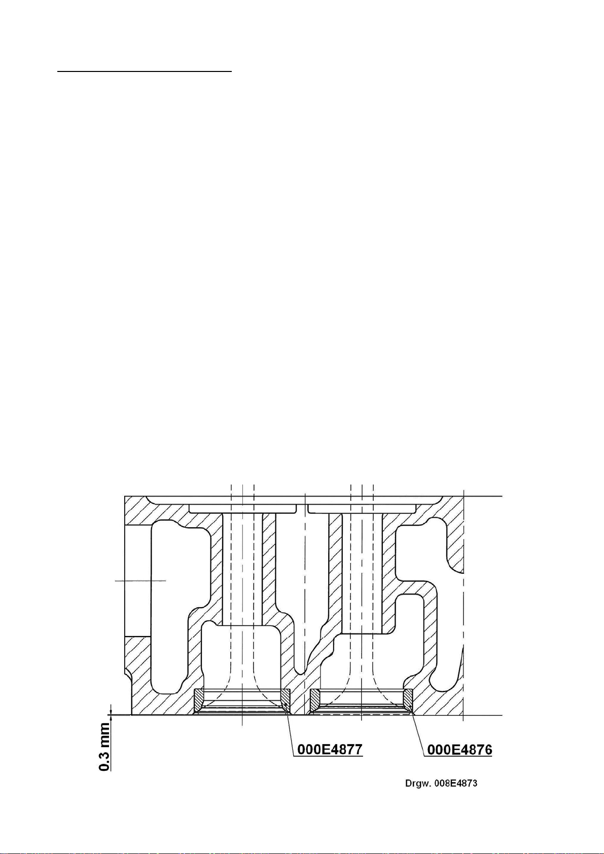
C19
Replacement of valve seats
The valve seat rings should be replaced when, after repeated millings and grindings, they
have been milled so far down that the valv e heads are more than 0.3 mm belo w the face of
joint of the cylinder head (see the sketch below).
1. Remove the valve springs an d valves as indicated previously in this section.
2. Place a lead plate or an annealed copper plate between the cylinder head and a bent
chisel and knock out the valve s eat ring with this (crowbar princ iple) by stic king one
end of the chisel under the rear edge of the valve seat ring.
IT IS IMPORTANT THAT THE FILLING PIECE IS USED BETWEEN CYLINDER HEAD
AND CHISEL IN ORDER TO AVOID DAMAGING THE CYLINDER HEAD.
Before fitting new valve seat rings, clean the bores in the cylinder head for same and check
that the holes are not oval.
Then warm up the cylinder head in hot water to about 100° C (212° F), after which fit, by
means of a punch, the valve seat rings having been cooled down beforehand in nitrogen or
carbon dioxide.
When fitting the valve seat rings, the difference of temperature between cylinder head and
valve seat ring is to be 220 – 250° C (430 – 480° F).
DO NOT KNOCK IN THE VALVE SEAT RING VIOLENTLY. ONLY ACTIVATE THE
PUNCH WITH A RATHER GENTLE BLOW IN ORDER TO FIT THE VALVE SEAT RING.
009W2329-R01
Page 40
C20
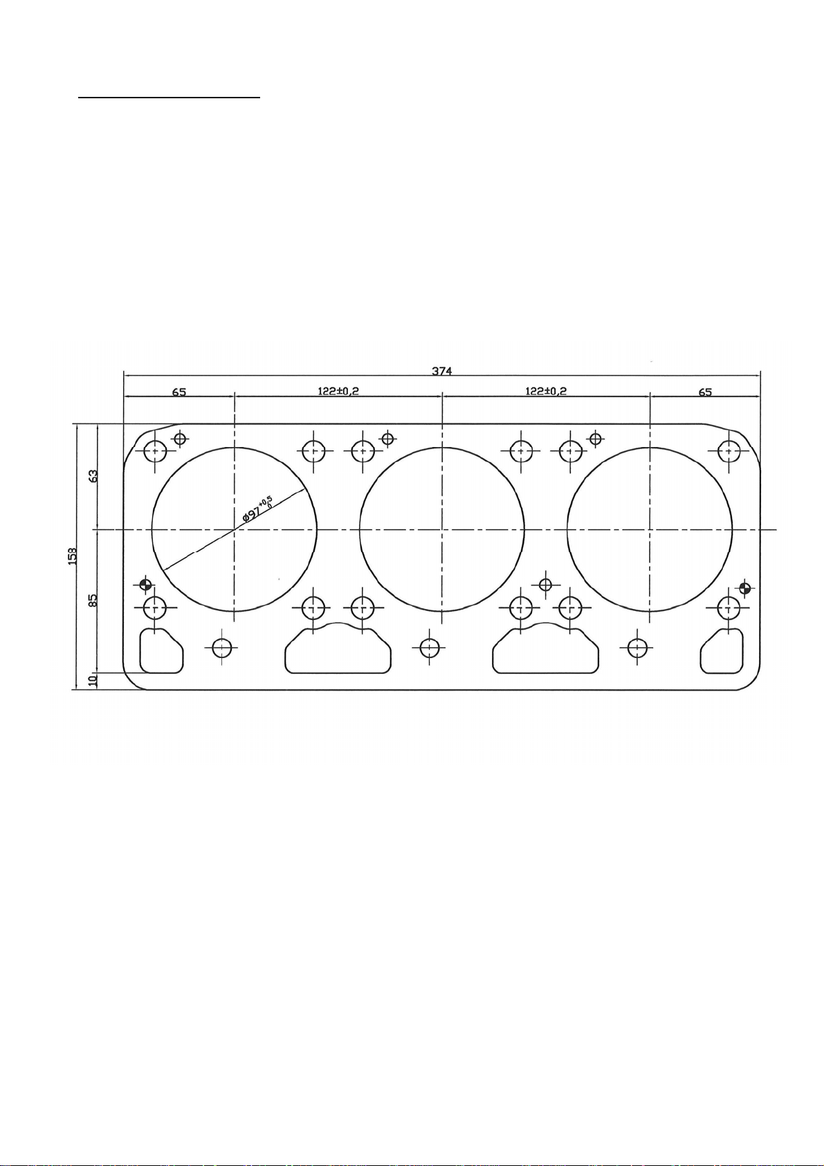
Cylinder head gasket
The cylinder head gasket is made from “Grafos eal” (Asbestos free) which is an expanded
graphite which is strengthened with a special 0.2 mm carbon steel inlay.
When replacing the cylinder head gasket, the grooves in the cylinder head must be
completely clean to obtain tightness.
If the cylinder head has been removed several time s, the metal around the studs may have
risen which can be checked by m eans of a straight-edge. If the me tal has risen, it must be
planned.
Drwg. 000E4789
009W2329-R01
Page 41
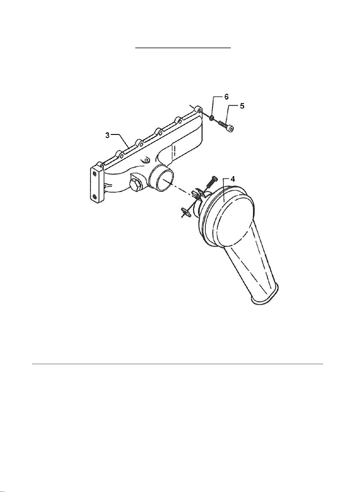
C21
Air inlet manifold arrangement.
Pos. Part No. Qty. Beskrivelse Description Benennung
3 000E4923 1 Indsugningsmanifold Inlet manifold Einlasssammelrohr
4 008E7310 1 Luftfilter Air filter Luftfilter
5 501A2363 12 Cylinderskrue Unbraco screw Unbracoschraube
6 522E0521 12 Låseskive Locking washer Arretierungsscheibe
009W2329-R01
Page 42
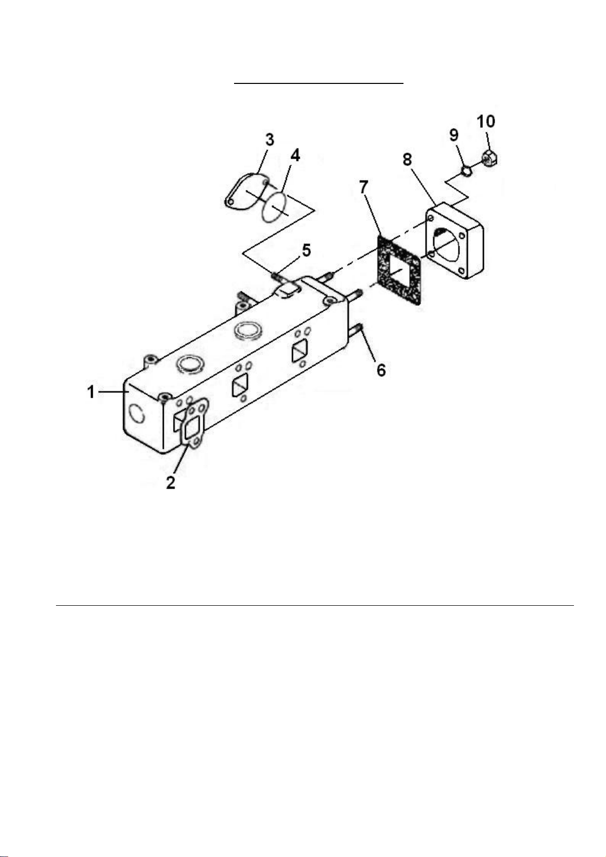
C22
Exhaust manifold arrangement.
Pos. Part No. Qty. Beskrivelse Description Benennung
1 000E7434 1 Vandkølet udstødningsmanifold Water-cooled exhaust manifold Wassergekühltes Auspuffsammelrohr
2 000E5028 3 Pakning for udstødningsmanifold Gasket for exhaust manifold Dichtung für Auspuffsammelrohr
3 008E9239 1 Flange Flange Flansch
4 560F1031 1 O-ring O-ring Abdichtung
5 500C2363 2 Sætskrue M8x20 Set screw M8x20 Setzschraube M8x20
6 503N2367 2 Tapskrue M8x35 Stud M8x35 Stiftschraube M8x35
7 000E5360 1 Udstødningspakning Exhaust gasket Auspuffdichtung
8 000E7788 1 Udstødningsflange Exhaust flange Auspuffflansch
9 522F1020 4 Fjederskive Spring washer Federscheibe
10 510A3208 4 Møtrik M8 Nut M8 Mutter M8
009W2329-R01
Page 43

D1
SECTION D
FLYWHEEL
009W2329-R01
Page 44

D2
CONTENTS
Removal and refitment of flywheel ............................................ page D 3
V-belt pulley fitted on flywheel ................................................... page D 3
Replacement of gear rim ........................................................... page D 4
009W2329-R01
Page 45
D3
Removal and refitment of flywheel
1. Mark the flywheel in propor tion to the crankshaft out of consideration for the other
marking of the outer diameter of the flywheel.
2. Slacken the V-belt for the charging alternat or and tak e it clear of the V-belt pulley of
the flywheel.
3. Remove the six bolts securing the flywheel to the crankshaft.
4. Lift off the flywheel.
Refitment is to be carried out in reverse or der. Smear the bolts with some Loctite or
something similar and tighten them with a torque of 147±7 Nm (15.0±0.7 kpm).
When dismounting the flywheel please note to fit the flywheel in the same position as before.
This only due to the timing marks on the flywheel and not due to the balance of the flywheel.
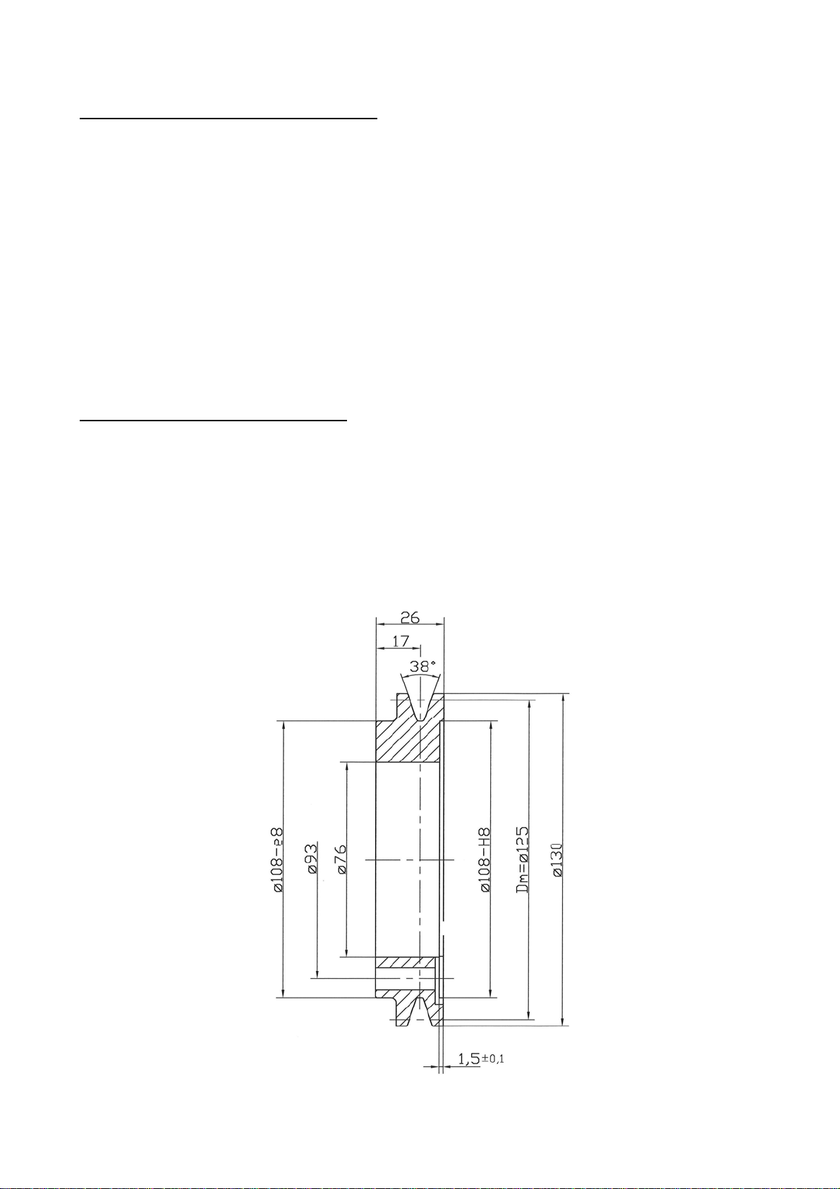
V-belt pulley fitted on flywheel.
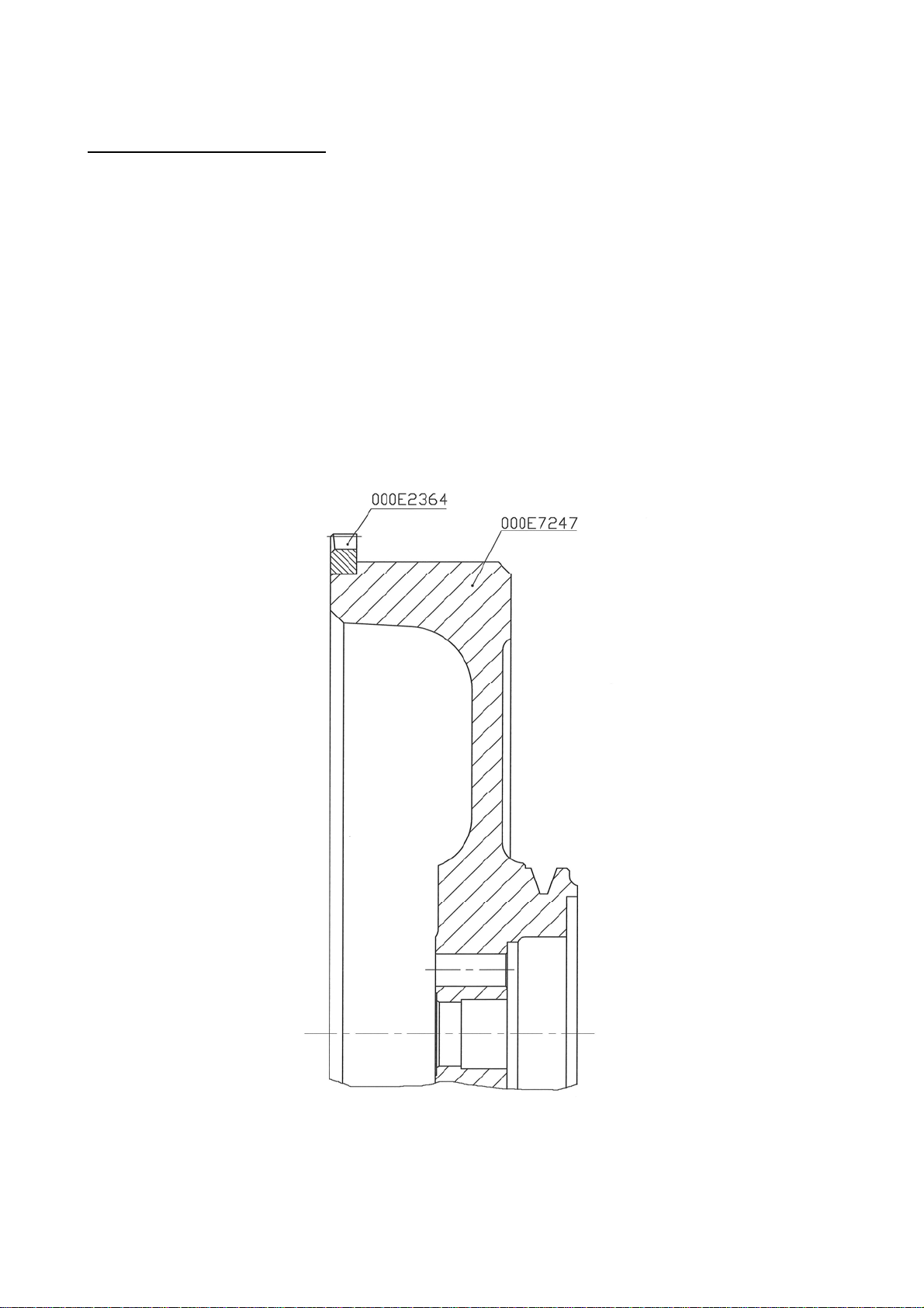
A V-belt pulley, as indicated on the drawing below, is fitted on the front end of the flywheel.
This V-belt pulley can be replaced by thr ee “A” grooves and diam eter 125 mm for operation
of e.g. bilge pump, winch or t he like. However, only max. 10 HP must be loaded from the
front of the engine.
The V-belt pulley may be ordered against number 023D2801.
Drwg. 000E4931
009W2329-R01
Page 46
D4
Replacement of gear rim
1. Remove the flywheel.
2. Saw with a hacksaw as far int o the gear rim as possible without damaging the
flywheel.
3. Split the gear rim in the sawed slot with a chisel.
4. Clean the recess on the flywheel.
5. Heat the new gear rim gradually to about 225°C (dark blue) and fit it. Make sure at the
fitting that the gear rim lies true against th e recess and that the chamfered edge turns
towards the starter engine.
Drwg. 008E7312
009W2329-R01
Page 47

E1
SECTION E
FRONT END COVER
009W2329-R01
Page 48

E2
CONTENTS
Dismounting of front end cover .................................................. page E 3
Mounting of front end cover ....................................................... page E 3
Front rotating weight .................................................................. page E 3
Replacement of front oil seal ring .............................................. page E 4
Replacement of bushes in the front rotating weight ................... page E 4
009W2329-R01
Page 49
E3
Dismounting of front end cover
1. Dismount the flywheel (see page D3).
2. Slacken the attachment of the end cover in engine block as well as in oil sump.
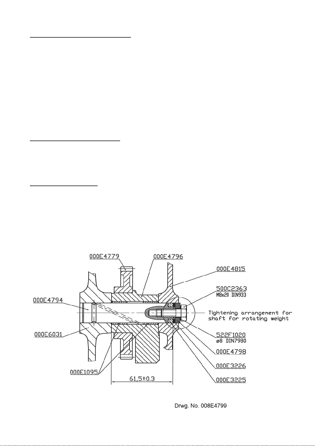
3. Dismount the tightening arrangement for shaft for rotating weight.
The tightening consists of two washers of different thickness and a fibre washer
assembled by a 8 mm screw.
4. Remove the end cover considering the guide spindles of the cover.
.
Mounting of front end cover
The mounting is carried out in reverse order of the dismounting, i.e. the tightening arrangement for
shaft for rotating weight is to be mounted last.
Front rotating weight
The front rotating weight is mounted below the front end cover, as shown on the drawing below
and overleaf.
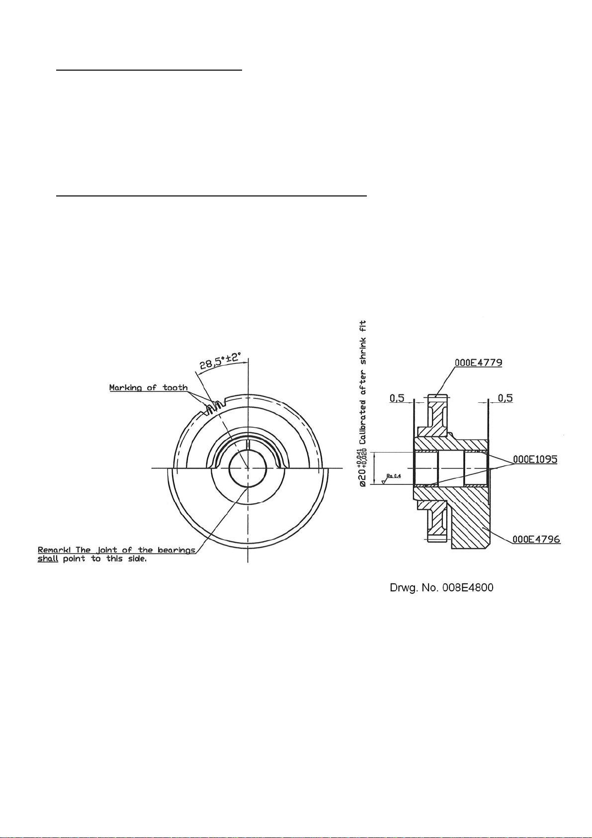
As will appear from the drawing overleaf the weight is marked in relation to a corresponding mark
on the gear wheel of the crank.
009W2329-R01
Page 50
E4
Replacement of front seal ring
A seal ring is mounted in the front end cover in order to avoid lubricating oil waste at the end of the
crank through the front end cover.
The seal ring can be replaced without dismounting the front end cover. It is, however, necessary to
dismount the flywheel.
Replacement of bushes in the front rotating weight
When replacing the bushes in the front rotating weight the new bushes must be calibrated with a
ball or reamed, with clearance and measures as indicated on the drawing.
009W2329-R01
Page 51

G1
SECTION G
REAR END COVER AND HAND START
009W2329-R01
Page 52

G2
CONTENTS
Rear end cover .......................................................................... page G 3
Dismounting of rear end cover .................................................. page G 3
Mounting of intermediate wheel and chain wheel ...................... page G 4
Tightening for shaft for intermediate wheel ................................ page G 4
Intermediate wheel .................................................................... page G 5
Rear of rotating weight (drawing) .............................................. page G 6
Mounting of rear of rotating weight ............................................ page G 7
Replacement of bush in the rear rotating weight
and intermediate wheel ............................................................. page G 8
Replacement of seal ring in rear end cover ............................... page G 8
Mounting of the rear end cover .................................................. page G 8
Chain adjuster ........................................................................... page G 9
Hand start .................................................................................. page G 10
009W2329-R01
Page 53
G3
Rear end cover
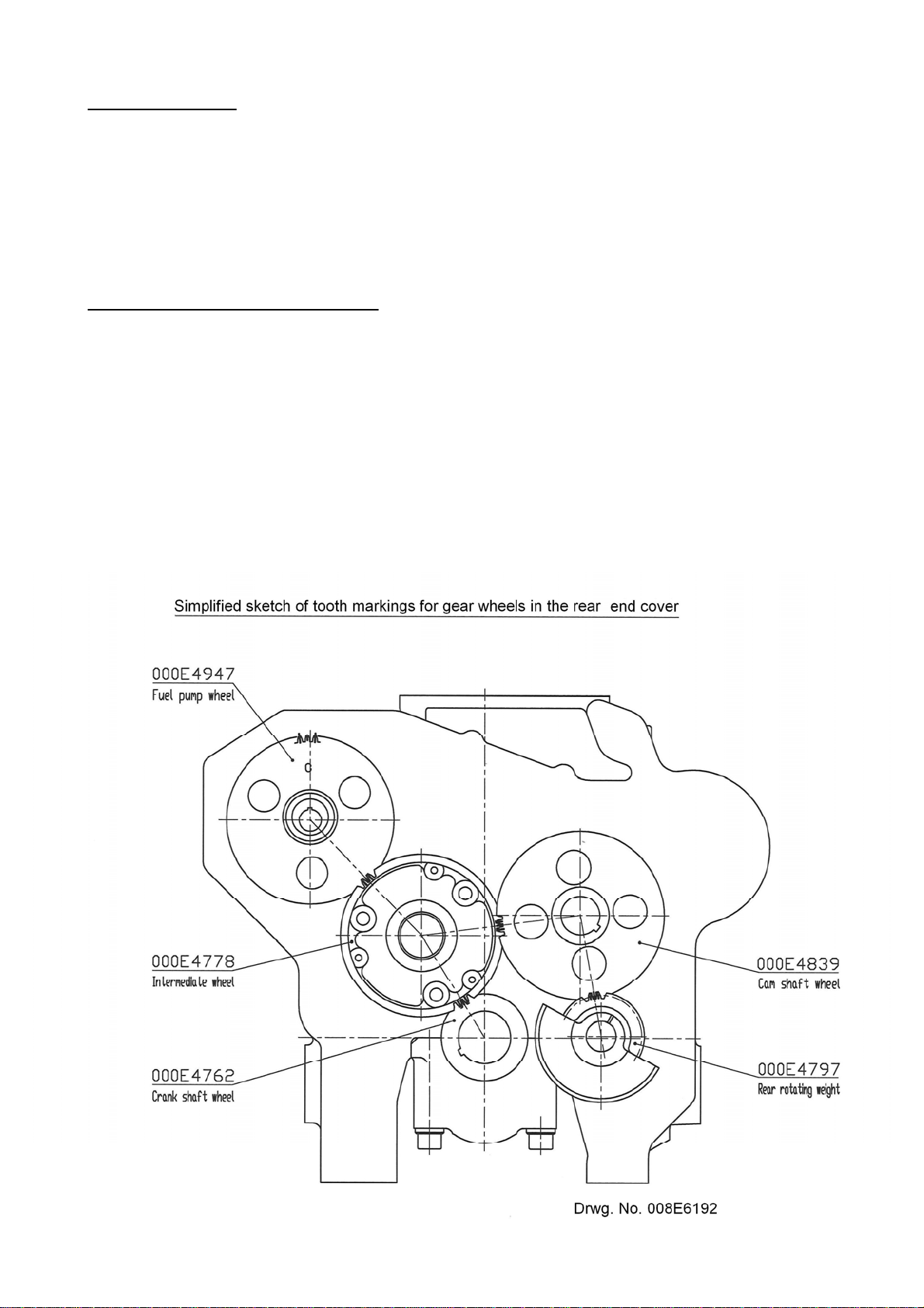
The rear end cover contains gear-wheel for crank, cam shaft, fuel pump,hand start,
lubricating oil pump, cooling water pump and rear rotating weight.
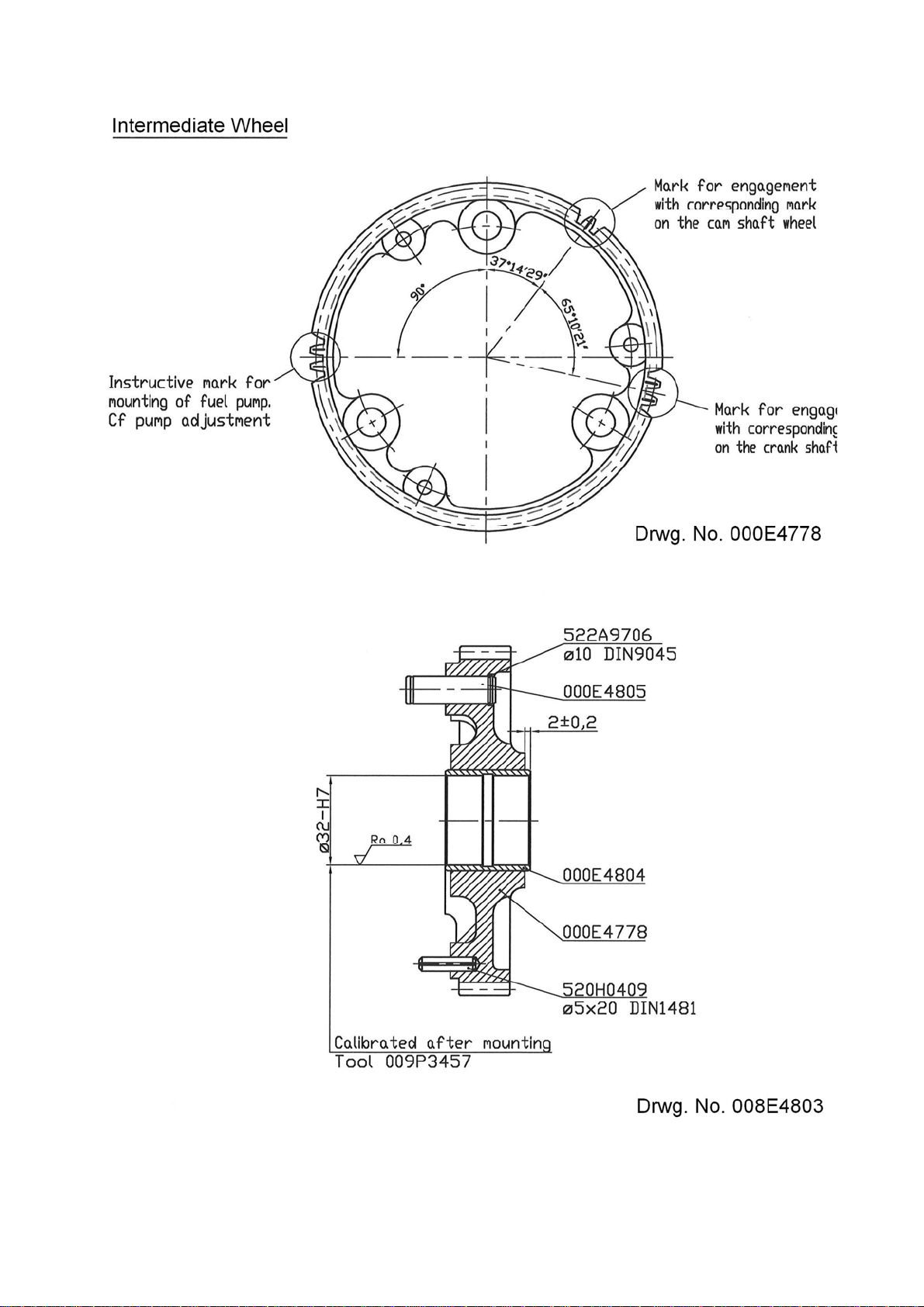
The gear-wheels are in the gear with each other through an intermediate wheel. The sketch
below indicates the marking of the gear-wheels which have been marked in relation to each
other so that their position to each other may easily be observed when being repared.
Dismounting of rear end cover
1. Dismount the gear from the engine.
2. Dismount the flexible coupling half on the crank.
3. Slacken the attachment of the end cover on engine block and oil sump.
4. Dismount the hand start and lower the chain into the end cover (see page G10).
5. Slacken the shaft seals for intermediate wheel and rear rotating weight and remove
the end cover.
6.
7.
8.
009W2329-R01
Page 54
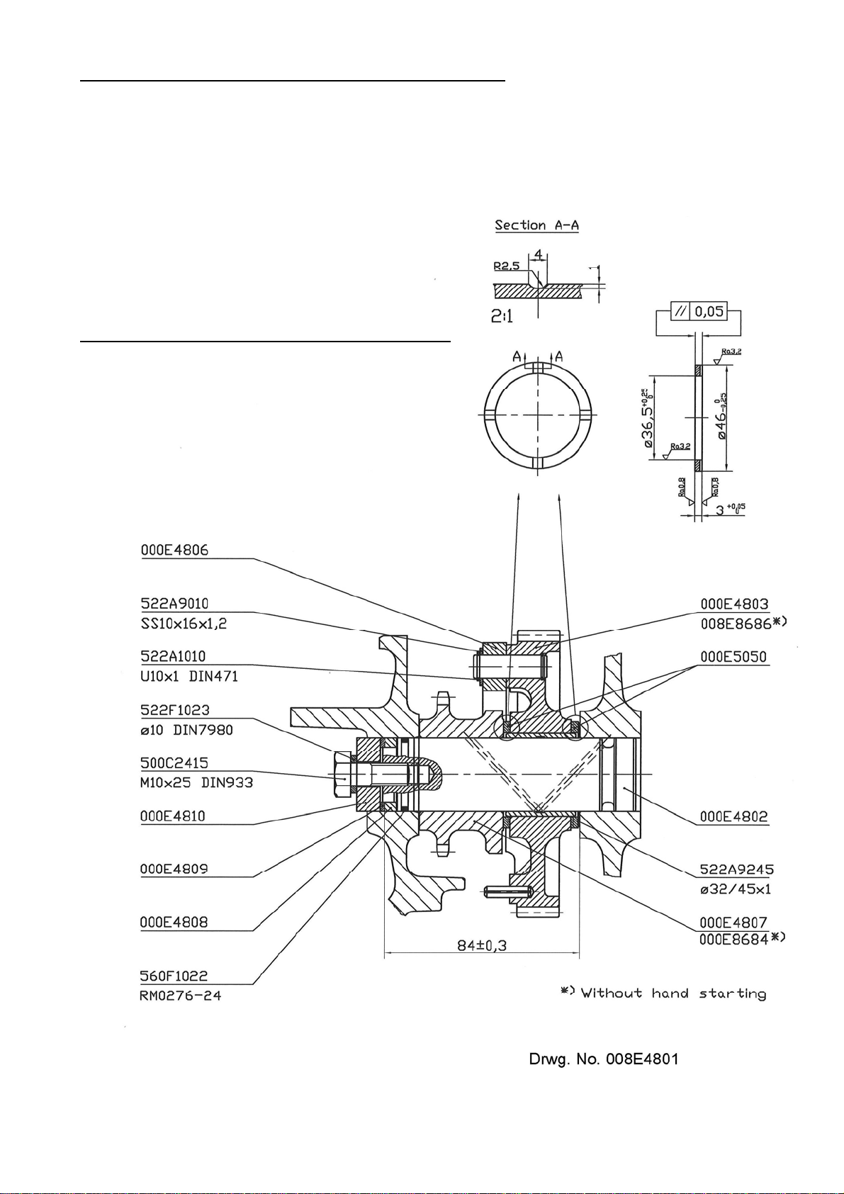
G4
Mounting of intermediate wheel and chain wheel
After the intermediate wheel has been placed on the shaft, and after the timing marks – as
indicated overleaf – have been adapted for the corresponding marks, the chain wheel for
hand start should be mounted on the same shaft.
The two thrust collars shown form part of the arrangement.
It is necessary – when mounting – to lubricate the
washer between block and thrust washers with
grease in order to secure that it keeps its position
during the mounting and that it does not slide down.
Tightening for shaft for intermediate wheel
The tightening consists of two washers and
a fibre ring as indicated below.
009W2329-R01
Page 55
G5
009W2329-R01
Page 56
G6
009W2329-R01
Page 57
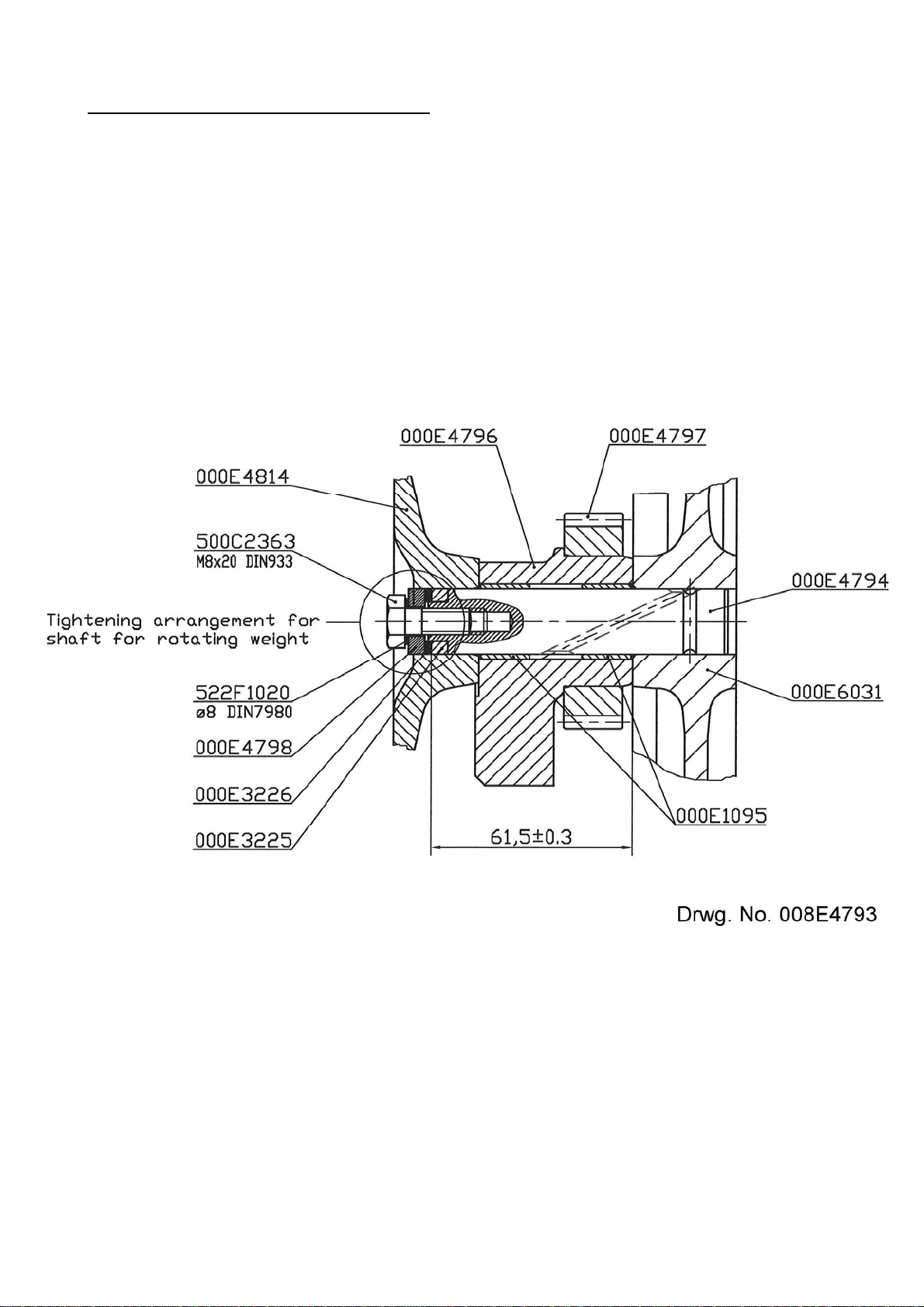
G7
Mounting of the rear rotating weight
Mount the rotating weight on the shaft pressed into the engine block and the tooth marking in
relation to the intermediate wheel should be observed.
After the end cover has been mounted, the tightening for shaft should be mounted in
accordance with the drawing below.
The tightening consists of two washers of different thickness and a fibre ring.
009W2329-R01
Page 58

G8
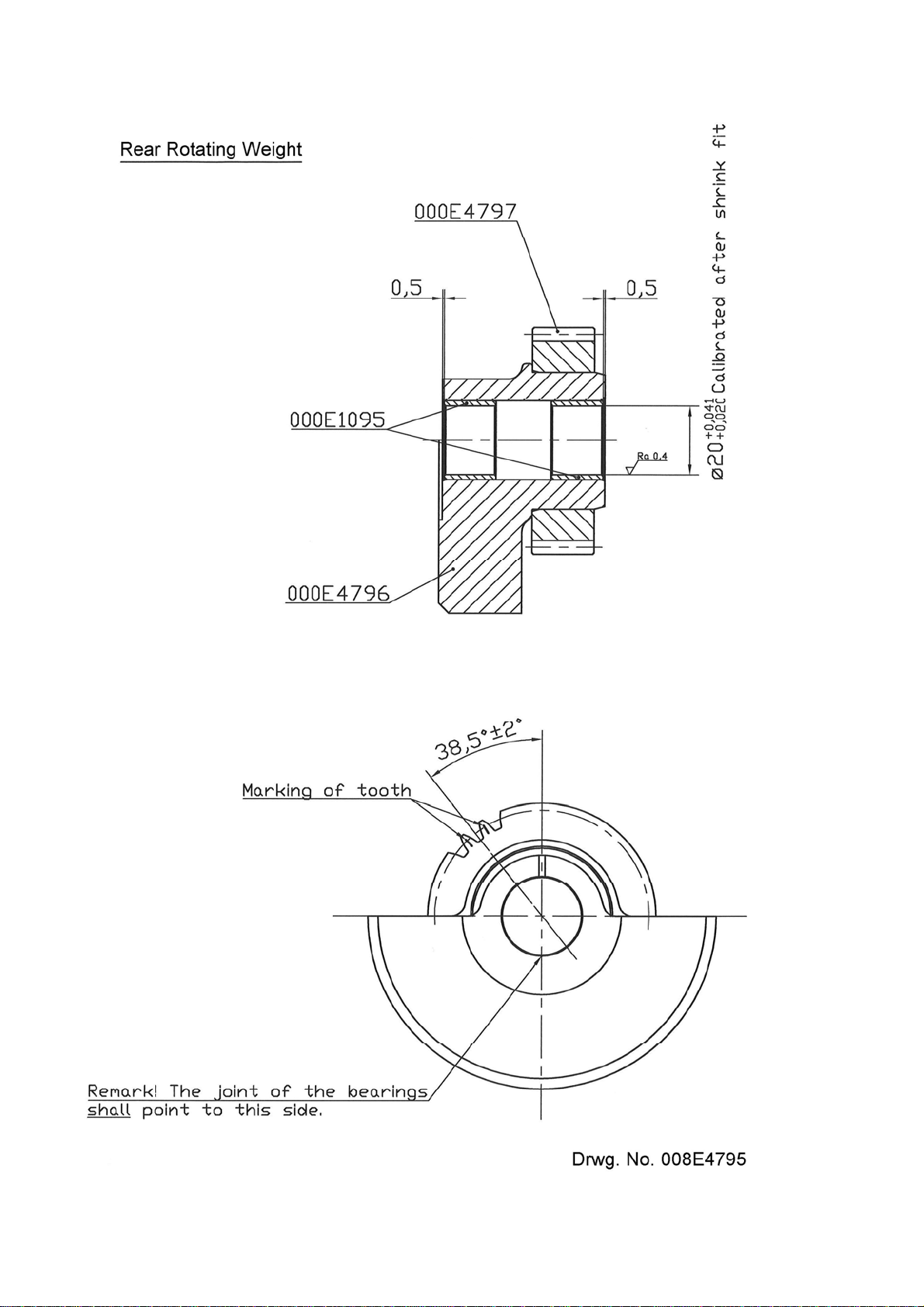
Replacement of bush in the rear rotating weight and intermediate wheel
Bushes have been mounted in both rear rotating weights as well as in the intermediate wheel.
These bushes can be replaced in case of wear and tear.
After the new bushes have been pressed in these should be calibrated with a ball or be reamed
with the correct measures and clearances as indicated on the drawings on page G5 and G6 for
rear rotating weight and intermediate wheel respectively.
Replacement of seal ring in rear end cover
A seal ring is mounted in the rear end cover in order to avoid leak of lubricating oil at the outlet
of the crank through the rear end cover.
It is possible to replace the seal ring without dismounting the end cover after the gearbox with
intermediate guard has been dismounted.
Mounting of the rear end cover
The mounting is carried out in reverse order of the dismounting, as the chain for hand start is to
be mounted on the chain wheel and then to be pulled up through the hole in the end cover with
a piece of string or the like, and here the hand start is to be ready-mounted later.
009W2329-R01
Page 59
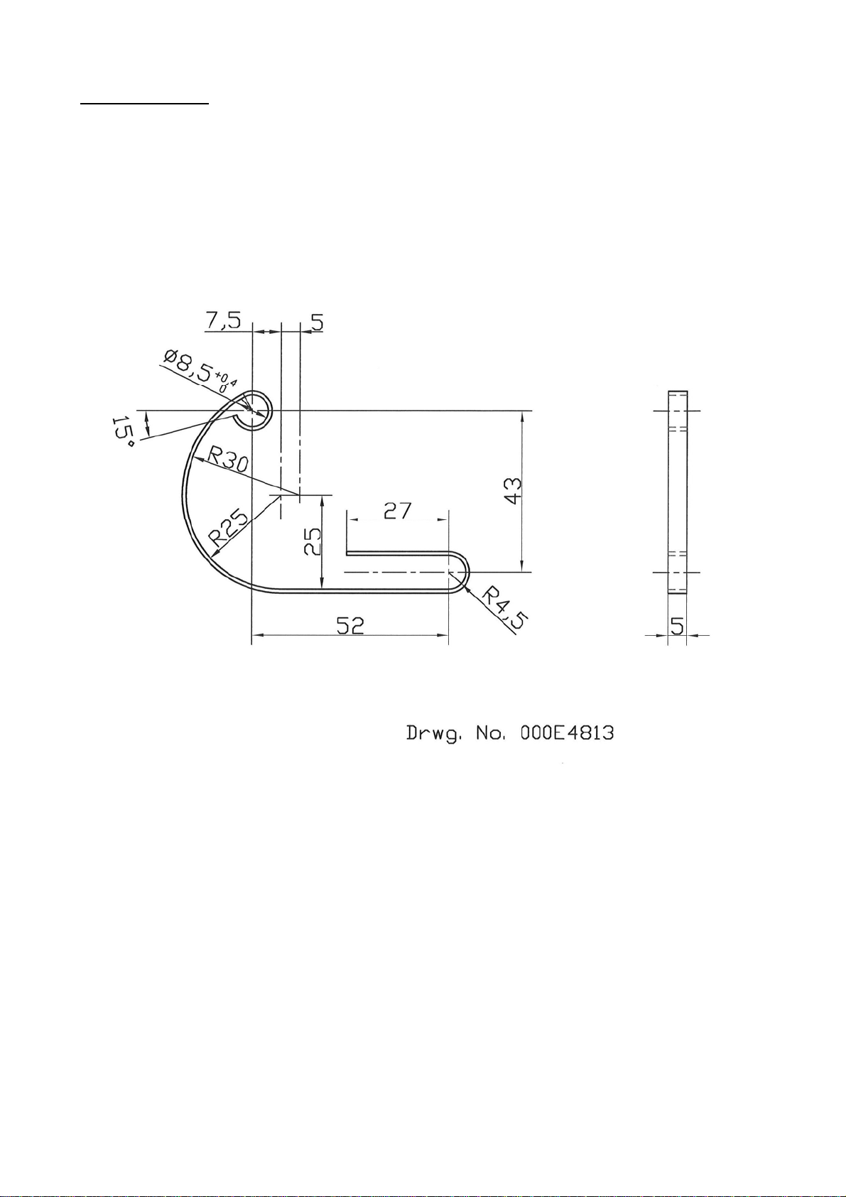
G9
Chain adjuster
The chain adjuster is mounted on two pins in the engine block.
The chain adjuster is self-adjusting and thus it does not require any adjustments in connection
with repairs in the end cover during which the chain is to be dismounted.
009W2329-R01
Page 60
G10
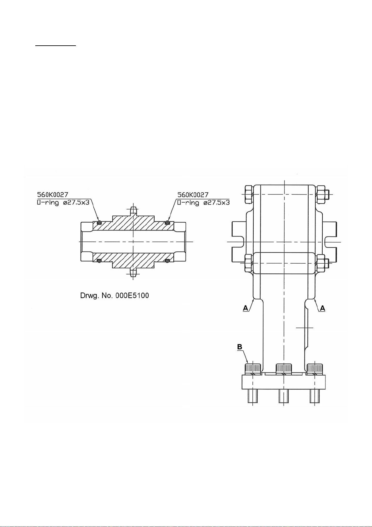
Hand start
The chain case is bolted on to the rear end cover, as indicated on the drawing below.
When dismounting remove the covers “A”, and this results in the chain being slackened and
then the chain wheel and shaft can be taken out.
Mounting is carried out in reverse order and it should be taken care that the O-rings for oiltightness are correctly placed in the grooves on the chain wheel shaft.
Dismount the chain case from the end cover by removing the bolts “B”.
009W2329-R01
Page 61

H1
SECTION H
FUEL SYSTEM
009W2329.XLS
Page 62

H2
CONTENTS:
Dismounting of the fuel pump ......................................................... page H 3
Mounting and Adjustment for fuel pump ......................................... page H 4
Specification of Numbers to Fig. 1 and 2 ........................................ page H 6
Fuel System ................................................................................... page H 7
Centrifugal Governor ...................................................................... page H 8
Function of the Centrifugal Governor .............................................. page H 9
Fuel Lift Pump ................................................................................ page H10
Fuel Filter ....................................................................................... page H11
Fuel Valve ...................................................................................... page H12
Causes and Remedies of the Fuel Pump ....................................... page H13
009W2329.XLS
Page 63

H3
Dismounting of the fuel pump
1. Dismount the bilge pump for lubricating oil from engine and gear.
2. Dismount the flange opposite of the fuel pump.
3. Take off the gear-wheel of the pump by slackening the clamping nut on the shaft of the
pump and pull off the gear-wheel.
4. Slacken the nuts in the flange of the pump and take out the pump.
REPAIRS OF THE PUMP SHOULD ONLY BE CARRIED OUT BY AUTHORIZED BOSCH
WORKSHOPS
009W2329.XLS
Page 64
H4
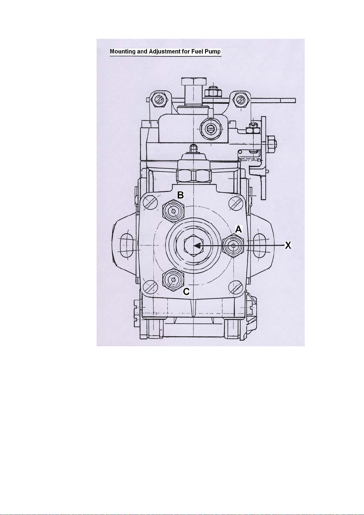
1. Turn piston No. 3 (rear) to TOP in the working stroke.
2. Mark the flywheel in this position in relation to the arrow mounted on the front edge of
the engine.
3. Measure 86 mm. arc measure from the TOP mark (to the right, when the flywheel faces
you).
009W2329.XLS
Page 65

H5
4. The pump should be adjusted for correct injection timing:
a. Adjust the key on the conical shaft of the pump so that it flushes with the outlet hole
B to the fuel valve for cylinder No. 3.
b. Remove the screw X and mount a dial indicator with a special sensing element
instead by means of a special holder for dial indicator.
c. Push in the dial indicator 2.0 mm.
d. Mount the flywheel for the pump loosely and turn it to the left, seen from the gear-
wheel side until the dial just indicates within the range of 0.01 mm.
5. Mount the pump on the engine by means of two nuts with washers and spring washers
so that the nuts are placed about the middle of the oblong holes in the flange of the
pump.
6. Mount the gear-wheel for the pump through the hole on the opposite side of the pump.
Fasten the gear-wheel on the conical pump shaft by means of a nut.
7. Mount the flange above the hole for mounting of the gear-wheel of the pump.
8. Mount the dial indicator again at the same place and in the same way and push it 2.0
mm in.
9. Turn the flywheel back from the 86 mm arc measure to 6 mm*) arc measure before the
TOP mark. The indicator is then to show 1.0 mm variation (1 turn).
If this is not so, fine-adjust either by moving the gear-wheel one tooth in relation to the
intermediate wheel (when indicating more than 0.7 mm) or by adjusting the placing of
the clamping nuts in the oblong holes in the flange of the pump (when indicating less
than 0.7 mm).
*)
According to the Service information SI0601, the arc measure has been changed
from 6 mm. to 20 mm. from engine no. 8395.
009W2329.XLS
Page 66

H6
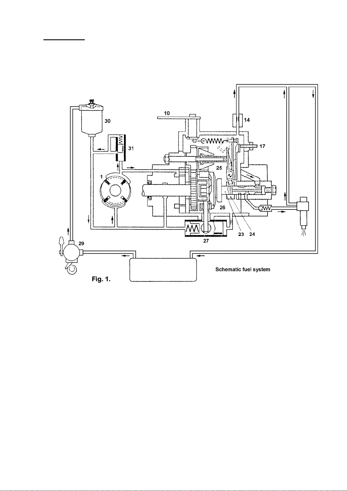
Specification of Numbers to Fig. 1 and 2
1. Feed pump
2. Drive shaft
3. Gear-wheel
4. Thrust washer
5. Governor shaft
6. Governor bush
7. Holder
8. Governor weight
9. Governor spring
10. Timing lever
11. Adjusting screw (idling)
12. Adjusting screw (max. r.p.m.)
13. Stop lever
14. Overflow throttle
15. Correcting lever
16. Bolt
17. Adjusting screw (full load)
18. Idle spring
19. Clamping arm
20. Starter spring
21. Starting lever
22. Delivery valve holder
23. Distributor piston
24. Governor slide
25. Fuel chamber
26. Cam disc
27. Injection timing piston
28. Roller cage
29. Lift pump
30. Fine filter
31. Pressure control valve
009W2329.XLS
Page 67
H7
Fuel System
The fuel is pumped by a lift pump (29 from the tank via a fine filter (30) to the internal wing
feed pump. This feed pump gives a constant quantity/revolution.
Through the pressure control valve (31), after the feed pump, a pressure is produced. Most
of the fuel flows through the pressure control valve back to the suction side. The remaining
part of the fuel flows through the inner chamber of the pump (fuel chamber) (25) to the high
pressure chamber of the distributor head and then it is led to cooling and bleeding and then
back to the tank through the overflow throttle (14).
The distributor piston (23) is activated by the drive shaft (2). By means of the cam disc (26)
and the rollers in the roller cage (28) the piston obtains an axial motion besides the rotary
motion.
The delivery (high pressure) takes place by means of the axial motion of the piston. The
distribution to the individual outlets (22) is through a slit in the distributor piston.
The injection stops when the governor slide (24) disengages the transversing hole in the
distributor piston. The fuel flows back into the fuel chamber of the pump (25).
The governor slide (24) is controlled by the centrifugal governor.
009W2329.XLS
Page 68
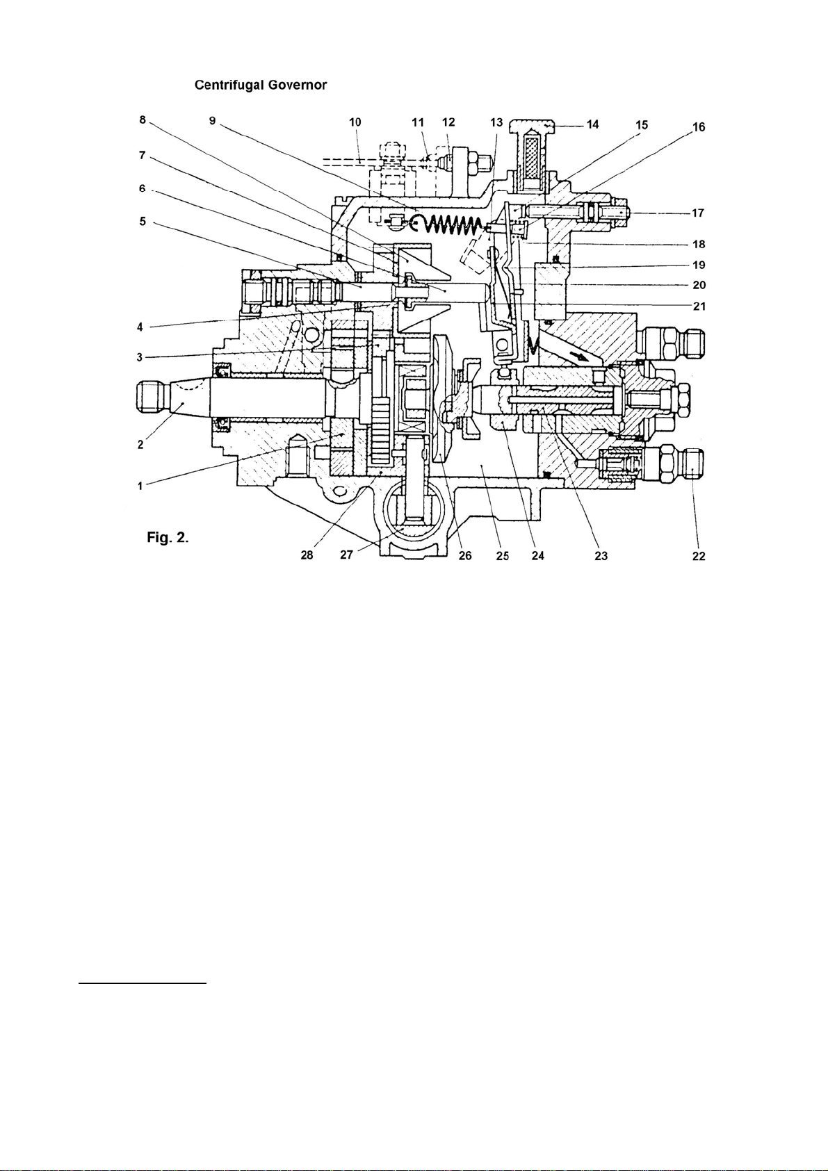
H8
The centrifugal governor is placed in the upper part of the fuel pump.
The holder (7) with gear-wheel is placed on the governor shaft (5) and is driven by the drive
shaft (2) via the gear-wheel (3) and a rubber shock absorber (vibration damper).
Four weights (8) are mounted in the centrifugal weight holder. They press on the axially
displaceable governor bush (6) via a thrust washer (4) with their pressure arms.
The governor arm group consists of starting lever (21), clamping arm (19) and correcting lever
(15). Starting lever and clamping arm are placed in the pump housing. In this way it is possible
to adjust the full load quantity by the adjusting screw (17) without influencing th adjustment of
the revolutions.
A leaf spring is placed on the starting lever (21) and it works as a starter spring. An axially
displaceable bolt (16) with idle spring (18) is placed in the upper part of the clamping arm (19).
The governor spring (9) is fixed in this bolt. The tension of the governor spring can be changed
by the timing lever (10). The starting lever (21) has a ball in the lower part connected with the
governor slide (24).
Injection Timing
On the under side of the fuel pump, at right angles in proportion to the longitudinal axis, the
spring-loaded injection timing piston (27) is. The roller cage (28) is turned influenced by the
feed pump pressure and via a mechanism. The injection timing is thus adjusted depending on
the revolutions.
009W2329.XLS
Page 69

H9
Function of the Centrifugal Governor
The revolutions of the engine are transmitted by the drive shaft (2) through gear-wheel to the
governor weights (8) and are transformed into centrifugal force there.
With stopped fuel pump, the starting lever (21) and the governor slide (24) are pressed into start
position by the starter spring (20). Through this automatic ful volume, when starting, is obtained.
When the r.p.m. of the engine goes up after start the function of the weak starter spring (20) is
taken over by the pressure from the governor bush (6). By this the starting lever (21) is pressed
against the clamping arm (19) and the starting volume is automatically declutched as the governor
slide (24) is displaced.
At low idling the governor spring (9) is not working.
The regulation is controlled by the idle spring (18).
By setting the governor spring (9) more or less with the timing lever (10) a lower or higher r.p.m.
is adjusted. The idle spring is pressed together.
The idling volume is adjusted by the adjusting screw (11) and the full load volume by the adjusting
screw (17).
Max. r.p.m. is adjusted by the adjusting screw (12).
The pump is stopped by means of a stop magnet built on to the fuel pump (not shown on the
sketch). This magnet closes the inlet port to the high pressure chamber in the distributor head at
electrical activation resulting in a dead stop magnet.
009W2329.XLS
Page 70
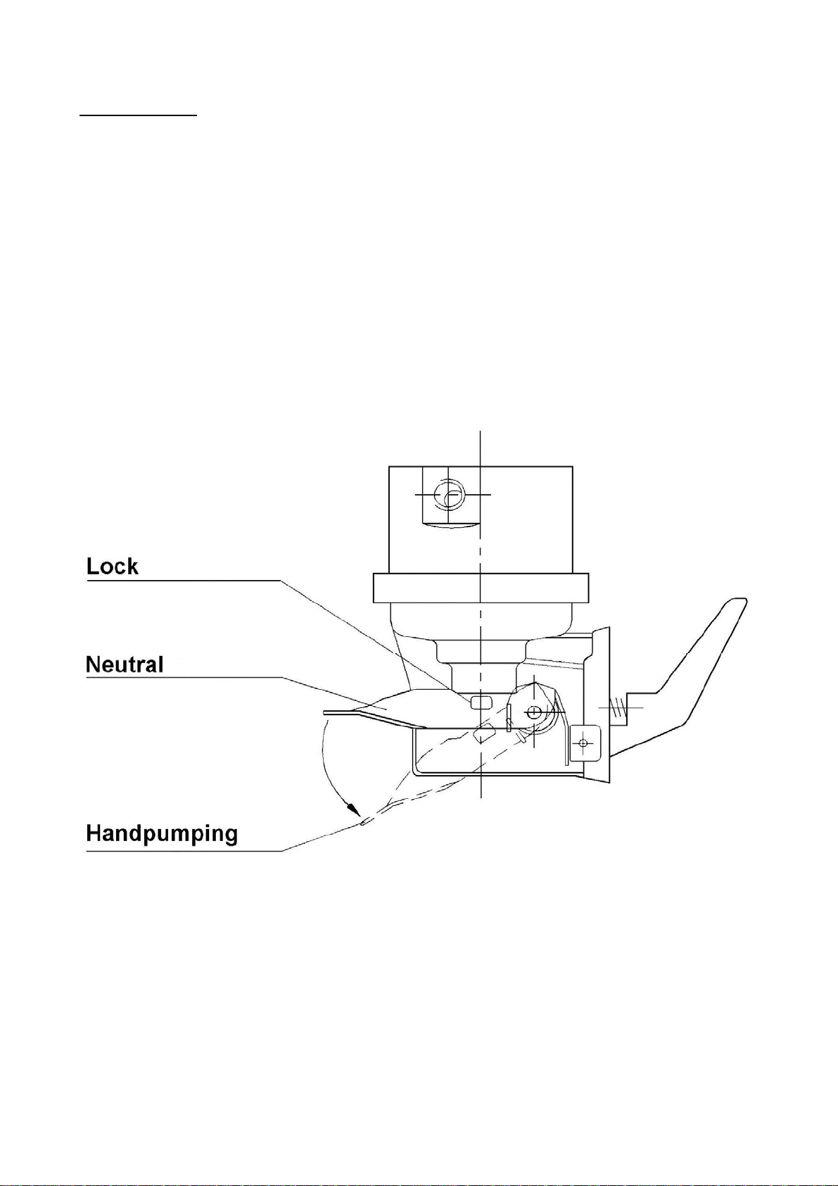
H10
Fuel Lift Pump
The fuel lift pump is a diaphragm type and is placed at the upper side of the rear end cover.
The pump is sealed and cannot be dismantled for repair or cleaning. It is driven by the
camshaft.
Workpressure is 35 – 55 kPa.
A hand pump is fitted, which can be used for priming and bleeding by standing engine.
After priming the lever must be put in neutral position, where it is locked. If priming
not is effective, it may be caused by the driving cam being in top position. The engine must
be turned to bring the cam in bottom position.
009W2329.XLS
Page 71

H11
Fuel Filter
The fuel filter used is a Bosch disposable one mounted to the port side on the front of the
engine.
The filter cannot be cleaned, but has to be changed every 300 operating hours, or if water
contamination is suspected.
Unscrew the filter casing by hand after the filter casing has been emtied for fuel via the
drain screw in the bottom of the filter casing.
Before fitting of a new filter the sealing surface of the filter casing should be cleaned. The
filter casing should now be filled with clea fuel before it is screwed on and tightened about
half a turn after the sealing surface fits tightly.
After changing the filter bleed the fuel system by actuating the manual handle on the fuel lift
pump and pump until the fuel, free from bubbles, runs out at the vent screw on the top of
the fuel filter. Tighten the screw and loosen the fuel pressure pipes at their connection on
the fuel valves and pump again with the fuel lift pump until fuel, free from bubbles, runs out
from the fuel pressure pipes.
009W2329.XLS
Page 72
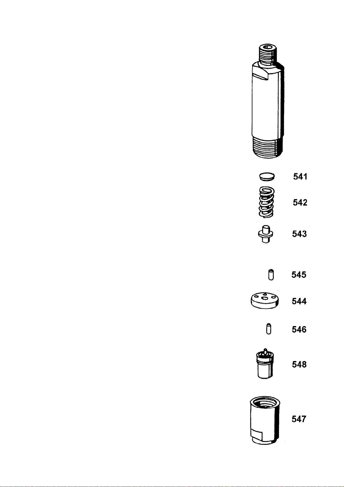
H12
The fuel valves are mounted in the cylinder head and are
secured here with tightening bars which are loosened when
dismounting the fuel valves.
Disassemble the fuel valves after the sketch beside and so
the nozzle can be exchanged and the pressure can be
adjusted at the washers (541).
Adjust the fuel valves by means of a pressure test apparatus
at 184 Kp/cm² *) opening pressure.
When using Bosch pressure testapparatus for nozzles you
are referred to Bosch infor-mation WPP 320/2 DK (500.8.76)
and this states test procedure and measures in detail.
The nozzle (548) is a Bosch nozzle DLLA 150P 34 combined
with a nozzle holder KBEL 78P 10/13 and this combination
makes the fuel valve (Item no. 610B9120) *).
The adjusting filling pieces for injection pressure are
obtainable from 1 mm to 1.975 mm thickness with 0.05 mm
from washer to washer.
When exchanging the nozzle the new nozzle has to be
cleaned in petrol as it has been prepared with a protective
oil. Both nozzle needle and nozzle housing should be
carefully cleaned.
When assembling the fuel valve tighten with 6 – 8 Kpm.
*)
According to Service information SI0601 the fuel valve has
been changed from 610B9120 (opening pressure 184 Bar)
to 610B9250 (opening pressure 230 Bar) from engine no.
8395 and again changed according to SI1102 from
610B9250 (opening pressure 230 Bar) to 610B9220
(opening pressure 210 Bar) from engine no. 8845.
009W2329.XLS
Page 73
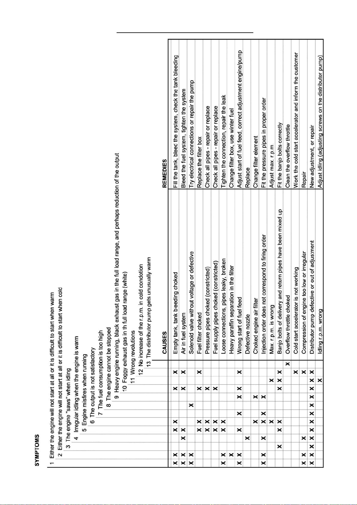
H13
Causes and Remedies of the Fuel Pump
009W2329.XLS
Page 74

Page 75

IJ1
SECTION IJ
PISTON, CONNECTING ROD AND CYLINDER LINER
009W2329-R01
Page 76

IJ2
CONTENTS
Disassembling of pistons and connecting rods .......................... page IJ 3
Assembling of pistons and connecting rods .............................. page IJ 3
Exchange of pistons .................................................................. page IJ 4
Measurement of piston .............................................................. page IJ 5-6
Piston rings ................................................................................ page IJ 7-8
Exchange of piston rings ........................................................... page IJ 9
Exchange of piston pin bearing in connecting rod ..................... page IJ 9
Arrangement of connecting rod (drawing) ................................. page IJ 10
Connecting rod bearings ........................................................... page IJ 11
Cylinder liner ............................................................................. page IJ 12
Measuring of cylinder wear ........................................................ page IJ 12
Dismounting of cylinder liner ..................................................... page IJ 12
Mounting of cylinder liner........................................................... page IJ 12
Test measurement of cylinder liner (drawing) ............................ page IJ 13
009W2329-R01
Page 77

IJ3
Disassembling of Pistons and Connecting Rods
1. Drain off the cooling water and the lubricating oil from the engine.
2. Dismount the cylinder head (see section C).
3. Remove any wear or soot edge which may be at the top of the cylinder liner with a scraper.
4. Turn the engine “upside down”.
5. Remove the oil pan.
6. Unscrew the connecting rod nuts and remove the bearing cap from the connecting rod.
7. Fit the connecting rod bolts with protective caps (soft plastic hose or the like) in order
to avoid the crank being damaged.
8. Turn the piston in top position and press out the piston and the connecting rod of the
cylinder liner. The crank must be in the exact top position.
Note! On later engines the connecting rod nuts have been replaced by unbraco
screws and therefore item 7 can be omitted.
Assembling of Pistons and Connecting Rods
1. Put a slip ring over the cylinder liner.
(The slip ring may be made from a worn out cylinder liner , of which 2/3 should be removed and the remaining 1/3 should be turned weakly conical in the top end wanted.)
2. Place the crank in the top position.
3. Fit the connecting rod bolts with protective caps.
4. Lower the piston and the connecting rod down into the cylinder liner by means of the slip
ring and do observe that the piston ring gaps are staggered. It should further be checked
that the recess in the piston head is turned towards the fuel valve. Before fitting the
pistons and connecting rods lubricate the crank journals abundantly with lubricating oil.
5. Place the engine on the side or turn it “upside down”.
6. Remove the protective caps.
7. Fit the bearing cap with the bottom bearing shells.
8. Tighten the connecting rod nuts with a torque of 69 +/- 3 Nm (7 +/- 0.3 kpm). Use selflocking nylon nuts for the connecting rod bolts and replace the nuts after each
disassembling of the connecting rod.
Note! The numbers on the connecting rod must be placed as before the disassembling
of the engine and the numbers on the connecting rod and bearing cap must fit.
The bearing cap and the connecting rod are guided by two balls which you must have
in mind when assembling.
009W2329-R01
Page 78
IJ4
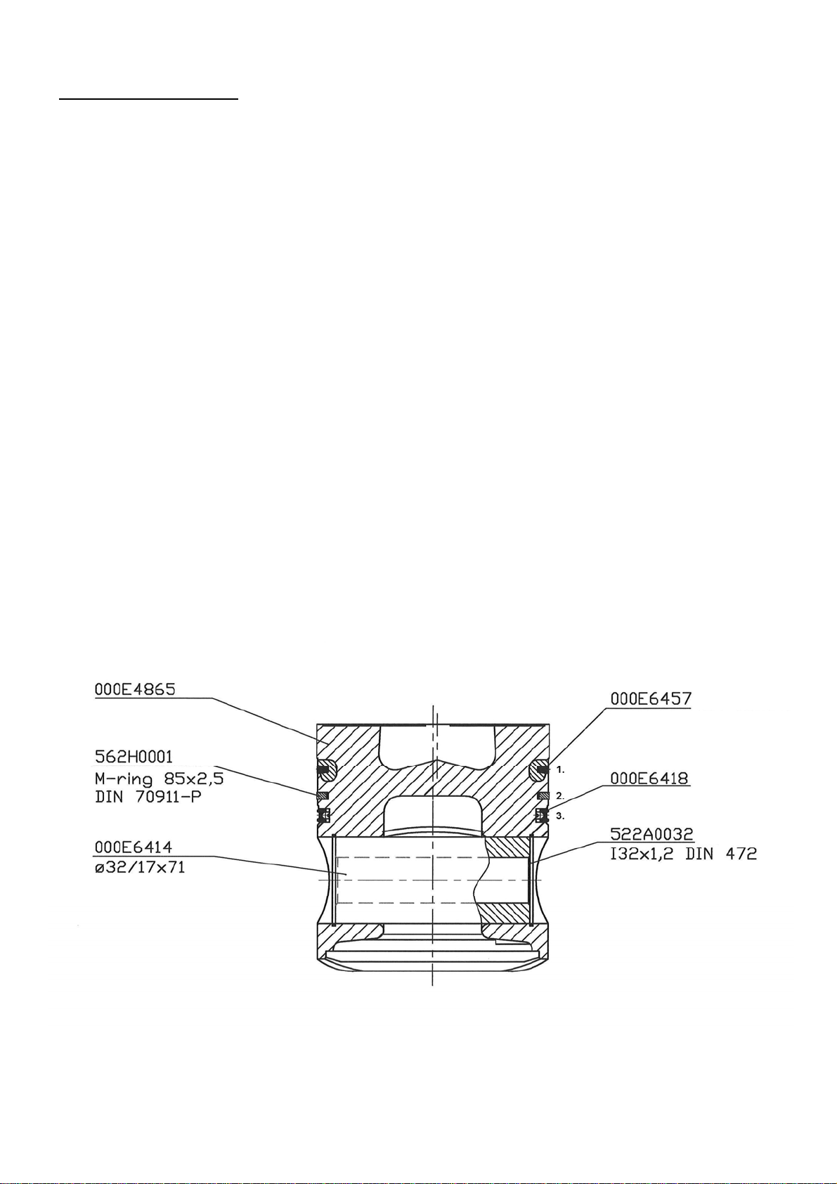
Exchange of Pistons
If the pistons are scored or very worn, exchange them for new ones.
This is carried out as follows:
1. Remove the pistons with connecting rods as stated on page IJ 3.
2. Take off one of the locking rings at the gudgeon pin.
3. Knock out the gudgeon pin with a punch.
4. Place the new pistons upside down. Pour a little spirit into them and light it.
The heating can also take place on a boiling plate.
5. When the piston has reached a temperature of about 100°C, smother the fire. Place the
connecting rod in the piston before the oiled gudgeon pin is pushed in.
It is recommended to cool down the gudgeon pin first, e.g. in a deep freezer or by means
of nitrogen or carbonic acid, if it is possible.
6. Relock the gudgeon pin with the locking ring.
Carefully observe that the piston is placed correctly in proportion to the numbering on the
connecting rod.
Weight of piston complete: 1,088 grams ± 7 grams.
009W2329-R01
Page 79
IJ5
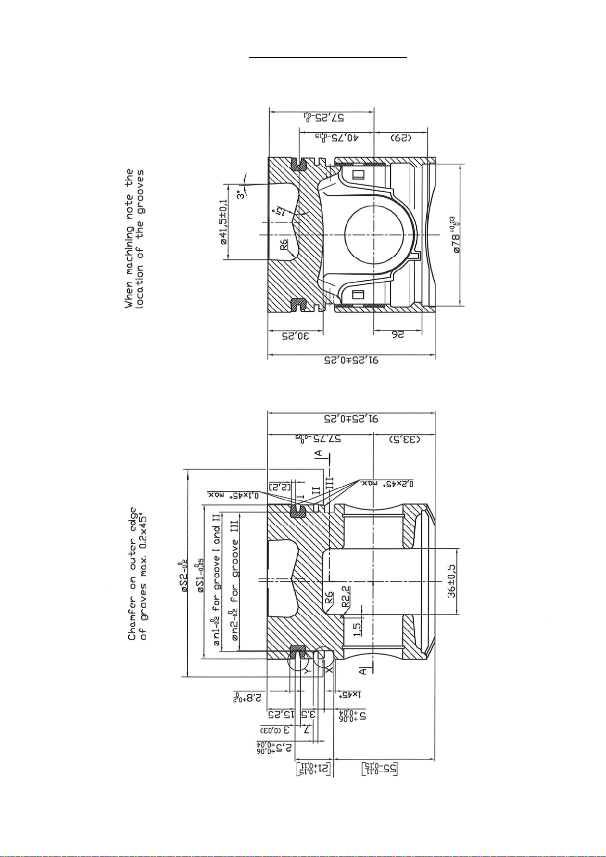
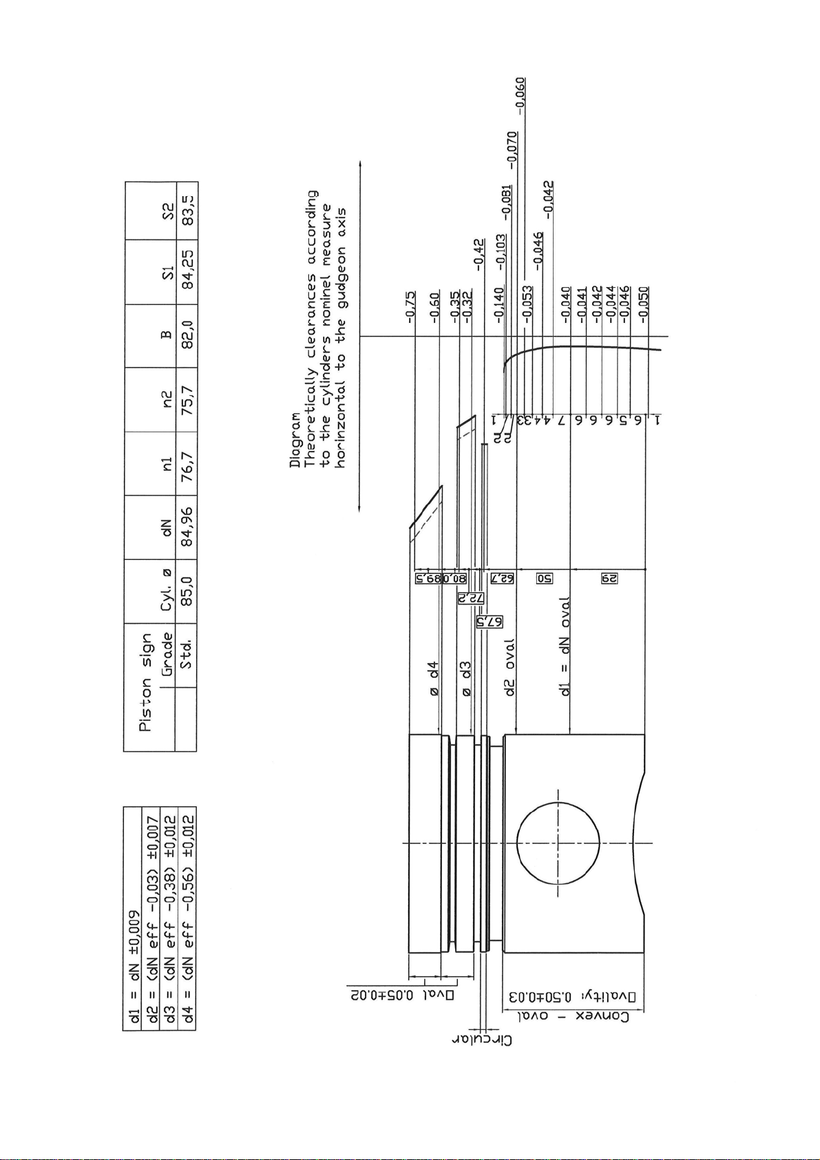
Measurements for Piston
009W2329-R01
Page 80
IJ6
009W2329-R01
Page 81
IJ7
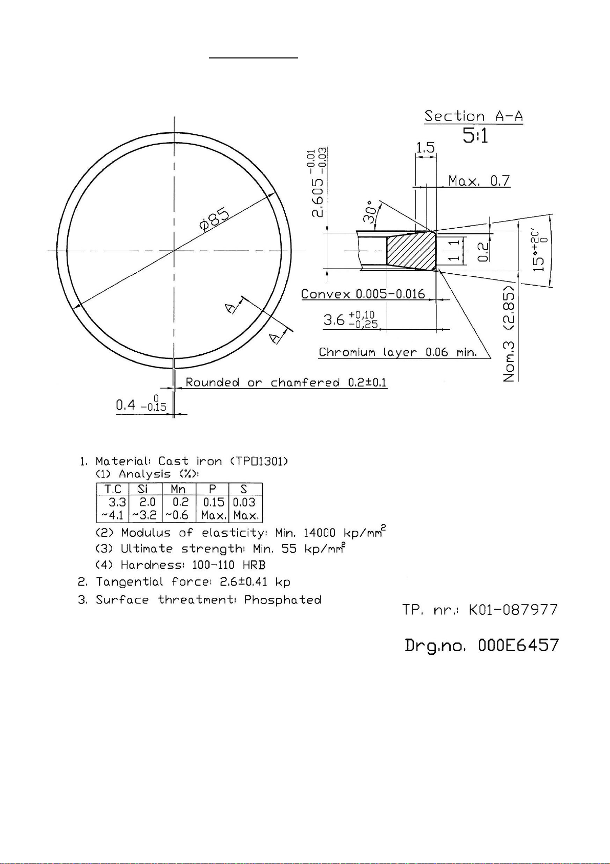
Piston Ring 1 (Please note page IJ4)
009W2329-R01
Page 82
IJ8
Piston Ring 3 (Please note page IJ4)
009W2329-R01
Page 83

IJ9
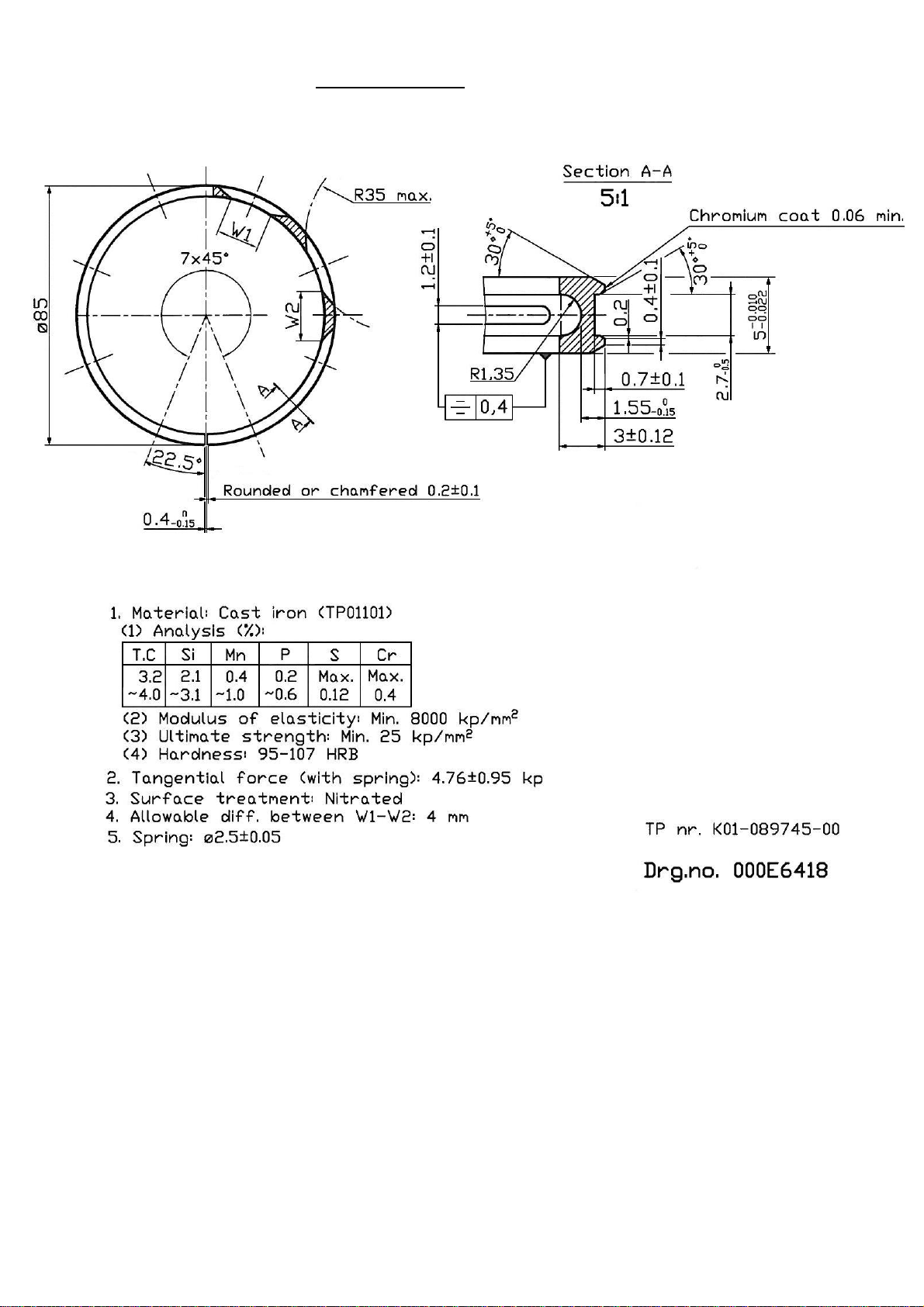
Exchange of Piston Rings
The piston ring gap is 0.3 – 0.45 mm (0.0118 - 0.0177 inch) in a new engine.
The wear of the piston rings ca n be seen by measuring the piston ring gap, and the piston rings
must be changed when this is max. 2.0 mm (0.0787 inch).
This is done as follows:
1. Take out the piston with connecting rod as stated on page IJ 3.
2. Remove the piston rings either by a spec ial pair of tongs or by m eans of two piec es of
string which have been folded. With the clos ed ends around the ends of the piston rin g,
the piston ring is extended and can be lifted clear of the piston.
The mounting is carried out in the reverse order after the piston ring grooves have been
cleaned. Rotary steel brushes or a steel scrapers should not be used as cleaning tools.
Each piston has three piston rings: two compre ssion rings and one oil scraper ring as shown
on the drawing page IJ4. The upper compre ssion ring are shown on page IJ 7 the lower
compression ring is a so called M-ring and the oil scraper ring is shown on page IJ8.
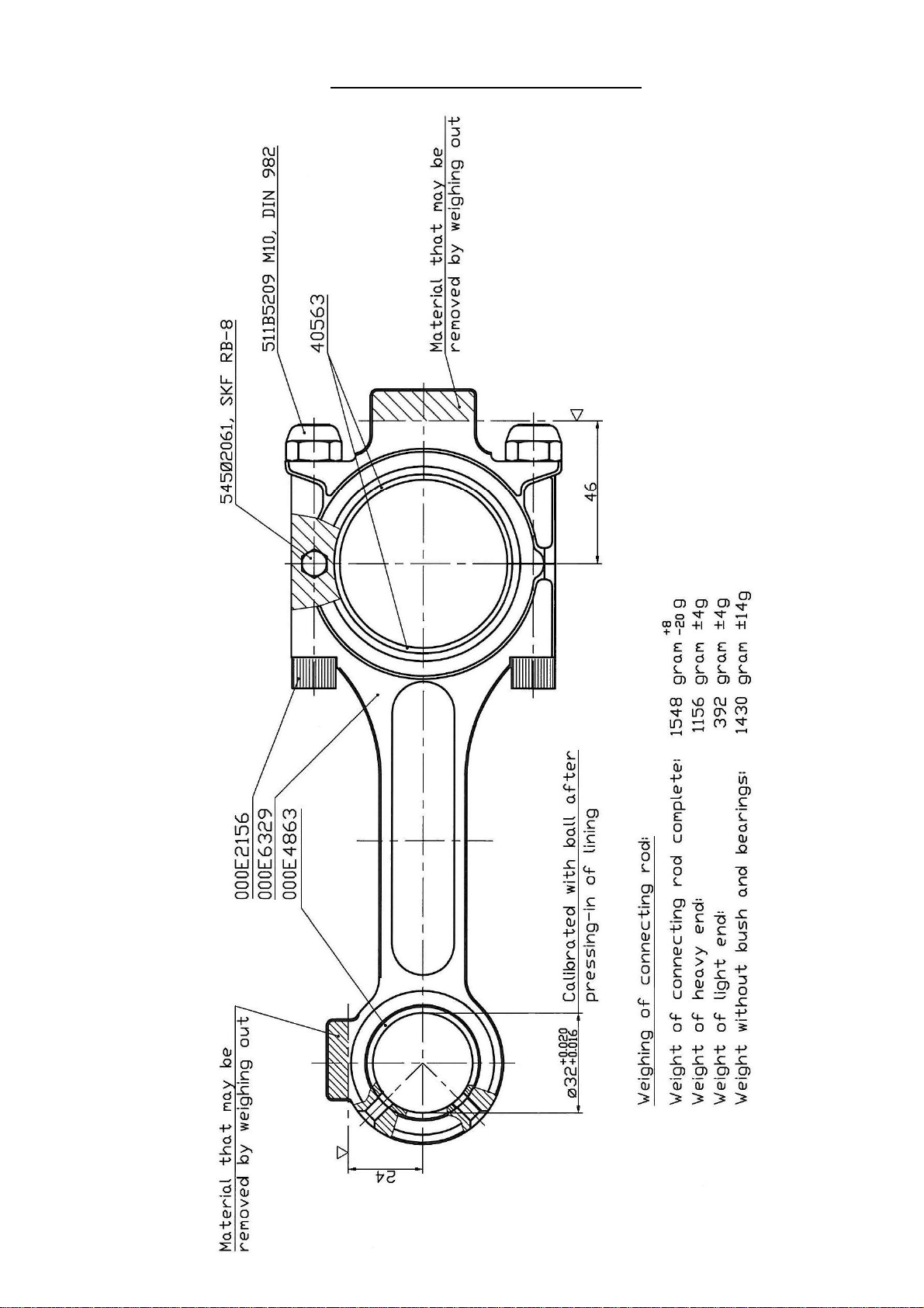
Exchange of Piston Pin Bearing in connecting rod
If heavy wear of the piston pin bearing in the connecting rod is found, it may be necessary to
exchange it. Particular attention should be paid when exchanging, as the bearing must be calibrated
to correct roundness and clearance after the fitting. This is either done with a calibration ball, as
indicated on page IJ10, or with a reamer with the tolerance mentioned.
009W2329-R01
Page 84
IJ10
Arrangement of Connecting Rod
009W2329-R01
Page 85

IJ11
Connecting Rod Bearings
The connecting rod bearings are in two parts and consists of two steel shells in which a thin layer of
bearing metal is cast.
The connecting rod bearings must be exchanged if they are scratched or if the “red” layer between
the bearing metal and the steel shell can be seen faintly.
When grinding the crank journal, connecting rod bearings can be supplied in following undersize:
0.6 mm (0.02362inch) (see section L).
009W2329-R01
Page 86

IJ12
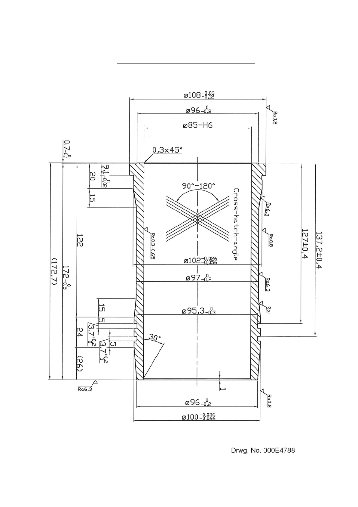
Cylinder liner
The bore of the cylinder liner is 85.000 – 85.020 mm (3.3464 – 3.3472 inch). The cylinder liner must
be exchanged when it is worn max. 0.3 mm (0.012 inch).
Measuring of Cylinder Wear
Place a new piston ring in the upper end of the liner where this is not worn. Measure the piston ring
gap with a feeler gauge. This will be e.g. 0.3 mm (0.012 inch). Place the piston ring lower in the liner
where it is worn and measure the piston ring gap again which is now e.g. 0.9 mm (0.0354 inch).
The wear of the liner is then (0.9 – 0.3) / 3 = 0.2 mm. That is: Largest measure less smallest measure
divided by 3 (approximate value for ¶).
The cylinder liner can also be measured with a cylinder template gauge.
Dismounting of Cylinder Liner
1. Remove the cylinder head (see section C page 7).
2. Take out the pistons (see page IJ 3).
3. Cover the connecting rod journals with a piece of oil paper or plastic.
4. Pull out the cylinder liners with a special tool or place the engine block on the side and knock out
the cylinder liners carefully with a wooden block as filling piece. Knock the liners from the bottom
and upwards.
Mounting of Cylinder Liner
There is no gasket between cylinder liner and the engine block at the top. The joint faces must
therefore be completely clean and without burrs. Grind with abrasive compound, if required.
The rubber rings of the lower edge of the cylinder liner must be renewed at each disassembly and
they must not be twisted
The rubber rings and the collar may be supplied with a thin coat of jointing paste at the mounting.
When the above things are in order put back the cylinder liner in the engine block – by means of a
wooden block.
After the mounting you must check the clearance of the liner above the engine block. This clearance
must be 0.10 – 0.20 mm (0.0039 – 0.0079 inch).
when mounting.
009W2329-R01
Page 87
IJ13
Test Measurements of Cylinder Liner
009W2329-R01
Page 88

Page 89

SECTION L
CRANKCASE, CRANKSHAFT,
MAIN BEARINGS AND OIL SUMP
L1
009W2329-R01
Page 90

L2
CONTENTS
Dismounting of crankshaft ......................................................... page L 3
Change of main bearings .......................................................... page L 3
Rear part of crank ...................................................................... page L 4
Rear gear-wheel and rear part of crank ..................................... page L 5
Marking of front gear-wheel on crank ........................................ page L 6
Front part of crank ..................................................................... page L 7
Repair dimensions of crakshaft ................................................. page L 8
Connecting rod journals ............................................................ page L 8
Main bearing journals ................................................................ page L 8
Main bearings ............................................................................ page L 8
Oil sump .................................................................................... page L 9
009W2329-R01
Page 91
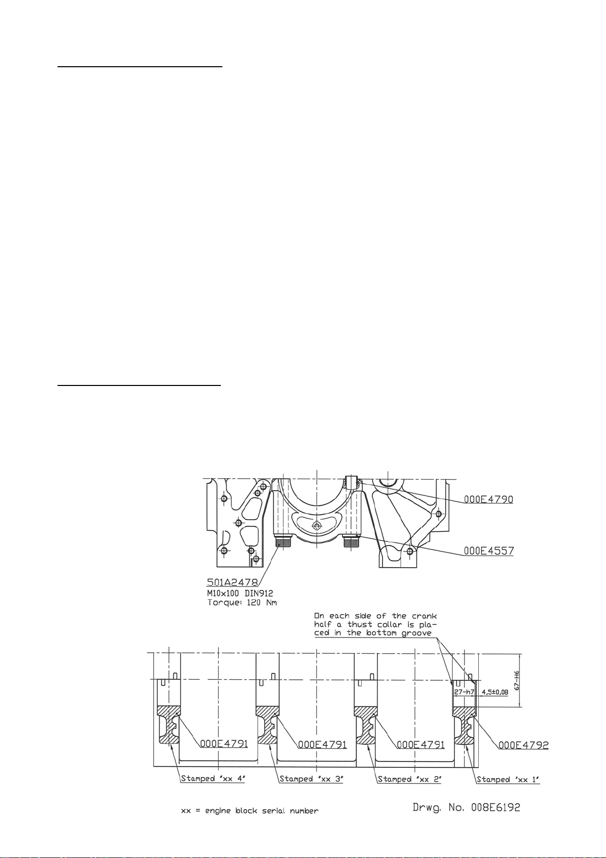
Dismounting of crankshaft
1. Remove the cylinder head with manifold (see section C page 4).
2. Dismount the flywheel (see section D page 3).
3. Dismount the gear (see section R page 3).
4. Dismount the rear end cover (see section G page 3).
5. Turn the engine upside down.
6. Remove the oil sump.
7. Dismount the pistons and the connecting rods (see section IJ page 3).
8. Dismount the front end cover (see section E page 3).
9. Remove the bearing caps and lift out the crank.
The mounting of the crankshaft takes place in reverse order, the bearing caps being fastened
L3
at a torque of 12 kpm (86.8 ft.lbf). Further make sure that the two thrust collars are correctly
fitted in accordance with the drawing below.
Change of main bearings
Proceed in the same way as when dismounting the crankshaft.
As will appear from the drawing below, the caps are stamped in proportion to corresponding
part of the engine block. Observe this marking when disassembling.
009W2329-R01
Page 92
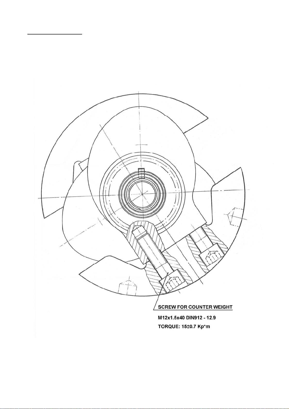
L4
Rear part of crank
The drawing below shows the rear part of the crank with screwing-on of the counter weights of
the crankshaft.
Drwg. No. 008E4757
009W2329-R01
Page 93
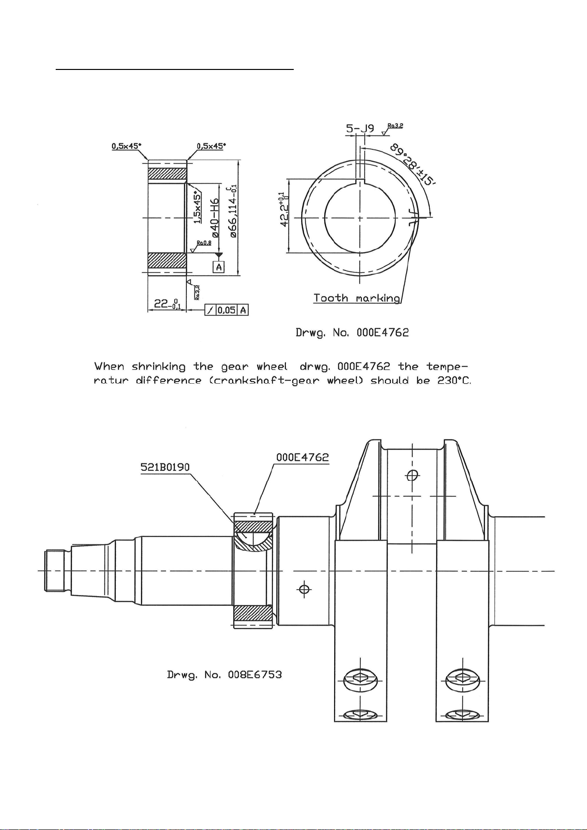
Rear gear-wheel and rear part of crank
L5
009W2329-R01
Page 94
L6
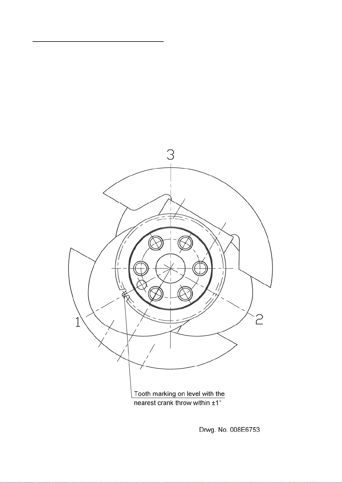
Marking of front gear-wheel on crank
The front gear-wheel on the crank drives the front rotating weight and is marked in proportion to
this and in accordance with the drawing below.
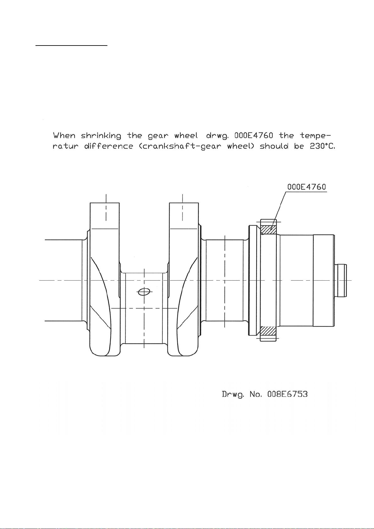
The gear-wheel has been shrinked on the shaft. When shrinking on a new gear-wheel there
should be a difference of temperature between the crankshaft and the gear-wheel of 231 C.
Further see the drawing overleaf.
009W2329-R01
Page 95
Front part of crank
L7
009W2329-R01
Page 96
L8
Repair dimensions of crankshaft
The crankshaft is made of drop-forged, heat-treated steel. Thus it is possible to gring the
crankshaft without subsequent surface treatment.
The crankshaft must never be repaired with hard chromium-plate or metal feeding, but only by
grinding in accordance with the below mentioned measures and tolerances to which we supply
undersize bearings.
The crankshaft should be ground, if it is oval and the smallest diameter is 0.05 mm (0.002 inch)
below the diameter it had when leaving the factory.
Connecting rod journals
Standard .................................................................. 53.987 – 54.000 mm (2.1255 – 2.1260”)
0.6 mm undersize .................................................... 53.387 – 53.400 mm (2.1019 – 2.1024”)
Clearance between bearing and journal…………..…..0.028 – 0.068 mm (0.0011 – 0.0027”)
Main bearing journals
Standard .................................................................. 61.981 – 62.000 mm (2.4402 – 2.4409”)
0.6 mm undersize .................................................... 61.381 – 61.400 mm (2.4166 – 2.4173”)
Clearance between bearing and journal .................. ..0.048 – 0.112 mm (0.0019 – 0.0044”)
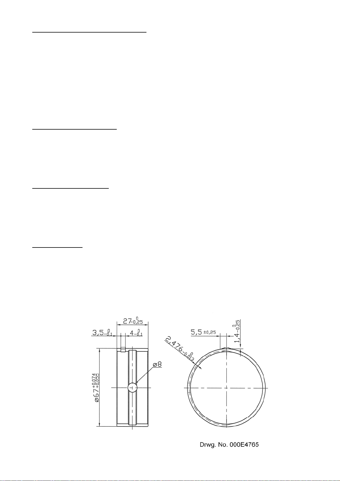
Main bearings
The engine is fitted with four two-piece main bearings as shown on the drawing below.
The bearings must be changed when the “red” layer under the bearing metal can be seen
faintly, or if the bearings are much scratched.
Bearing shell: C10 2.1 mm thick
Bearing material: tin aluminium with net structure
External surface: tinned 0.001 mm thick
009W2329-R01
Page 97
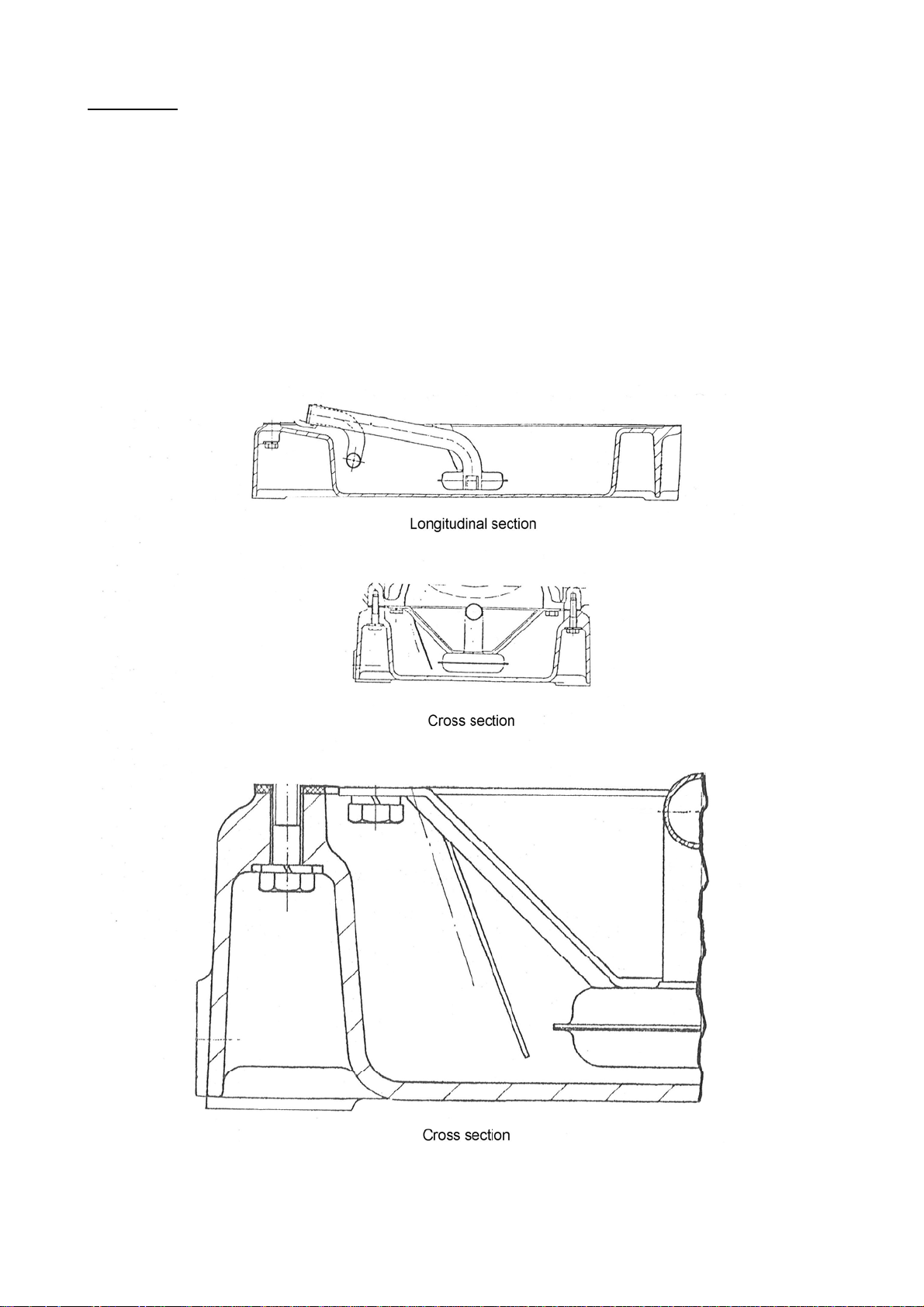
Oil Sump
The engine is fitted with an oil sump of cast iron. The oil sump is fixed to the crankcase and is
ensured correct position to this by means of guide pins.
Under the oil sump the suction strainer for the lubricating oil system is placed and pipe
connections for it.
The oil sump with pipe arrangement for lubricating oil system is shown on the drawing below.
L9
009W2329-R01
Page 98

Page 99

M1
SECTION M
CAMSHAFT, COMPLETE
009W2329-R01
Page 100

M2
CONTENTS
Camshaft ................................................................................... page M 3
Valve timings ............................................................................. page M 4
Guide for push rod ..................................................................... page M 4
Gear-wheel of camshaft ............................................................ page M 5
Drawing of push rod .................................................................. page M 6
Drawing of push rod guide ......................................................... page M 7
009W2329-R01
 Loading...