


|
|
|
|
Publ. No. |
|
|
|
009W2329 |
|
|
|
Aabenraavej 13-17, DK - 6340 Krusaa, Denmark |
|
|
|
|
Tel: +45 74 62 20 88 |
|
|
|
|
Fax +45 74 62 74 07 |
|
|
|
|
E-mail: bukh@bukh.dk – Internet: www.bukh.dk |
|
|
|
|
|
|
|
|
|
|
|
|
Work shop Manual
for
BUKH diesel engine
TYPE DV36/48
009W2329-R01
Contents
Section A … Introduction and technical data
Section B … List of tools
Section C … Cylinder head
Section D … Flywheel
Section E … Front end cover
Section G … Rear end cover and hand start
Section H … Fuel system
Section IJ … Piston, connecting rod and cylinder liner
Section L … Crankcase, crankshaft, main bearings and oil sump Section M … Camshaft
Section N … Lubricating oil system
Section O … Cooling water system
Section P … Electrical system
Section R … Gearbox ZF, BW7
Section S … Sail drive
Section T … Irregularities in operation - causes and remedies
Section V … Maintenance
009W2329-R01
A1
SECTION A
INTRODUCTION AND TECHNICAL DATA
009W2329
A2
CONTENTS
Introduction................................................................................ |
page A 3 |
Technical Data........................................................................... |
page A 4 |
Torques ..................................................................................... |
page A 5 |
Spare Part Nos. for Service Parts.............................................. |
page A 6 |
Torque and Rating Curves......................................................... |
page A 7 |
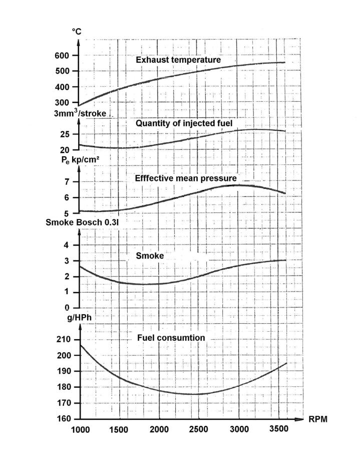
Results of Measurement............................................................ |
page A 8 |
Longitudinal Section of DV36 .................................................... |
page A 9 |
Cross Section of DV36 .............................................................. |
page A 10 |
Diagram of the Relation between the Total Weight, |
|
Speed and Horse Power of the Boat ......................................... |
page A 11 |
009W2329
A3
Introduction
BUKH DV36 is a 3-cylinder, water cooled, 4-stroke diesel engine with direct injection, giving an easy start at low temperatures, a low consumption of fuel and a low thermic load of the cylinder head.
The engines are specially designed to comply with the heavy demands made on stability, safety and environment now.
The technical structure of the engine with components and systems appears from the individual sections of this workshop manual and therefore this introduction contains no descriptions of this.
DV36 is designed with small installation dimensions compared to corresponding engine outputs on the market. This applies to both height, length and width. At the same time the weight of the engine is comparatively low and the proportion weight/horse power is in fact only
7.36 compared to corresponding engine outputs on the market with a corresponding factor of
8.28 and 8.48.
Being a 3-cylinder engine, DV36 is a naturally low level of vibration compared to 1- and 2- cylinder engines, but in order to obtain a further improvement of the vibration level, the rotating weight system has been continued on DV36 as it is known with great success from DV10 and DV20. DV36 with the anti-vibration system is thus free from unpleasant vibrations and may correctly be described as the less vibrating engine on the market.
DV36 is supplied either with sail-drive (type DV36SME) or with BW7 gear (type DV36ME). The type description S = saildrive, M = marine gear and E = with electric start.
The temperature of the exhaust gas is for DV36 max. 550°C, which is about 100°C below corresponding engine outputs on the market.
DV36 is delivered as standard with direct seawater cooling but may be alternatively be delivered with heat exchanger built integral with water cooled exhaust, keel cooler or radiator cooler.
009W2329
A4
TECHNICAL MAIN DATA |
|
|
WORKING PRINCIPLE……………………………………………………… ... |
4-STROKE |
|
BORE/STROKE...................... ................................ |
................................... |
85 mm / 85 mm |
CYLINDER VOLUME ............. ................................ |
................................... |
1.447 Litres |
COMPRESSION RATIO......... ................................ |
................................... |
18,5:1 |
COMPRESSION PRESSURE …. .................at 1800-3600 rpm………… .. |
46 Bar |
|
OUTPUT, CONTINOUS RATING.…. ............at 2400 rpm………..……… .. |
29.8 BHP - 21.9 kW |
|
ACCORDING TO ISO 3046……. ..................at 3000 rpm…………………..34.5 BHP – 25.4 kW |
||
|
..............at 3600 rpm…………………. 36.0 BHP - 26.5 kW |
|
OUTPUT, INTERMITENT RATING BHP.......at 4000 rpm......................... |
39.3 BHP – 28.9 kW |
|
MAX. TORQUE Kp*m............. ...................... |
at 1800 rpm.......................... |
9.2 Kpm – 90 Nm |
MAX. AIR CONSUMPTION .... ................................ |
................................... |
2214 Litres/min. |
ENGINE ROTATING, LOOKING AT FLYWHEEL .. ................................... |
CLOCWISE |
|
IDLING SPEED....................... ................................ |
................................... |
800 – 1000 RPM |
MAX INCLINATION, FORE AND AFT..................... ................................... |
15o |
|
HEEL, MAX. CONTINOUS ..... ................................ |
................................... |
30o |
NET WEIGHT INCL. ZF MARINEGEAR ................. ................................... |
265 Kg |
|
NET WEIGHT INCL. SAILDRIVE ............................ |
................................... |
290 Kg |
LOCATION OF ENGINE SERIAL NUMBER ........... ................................... |
ON CRANKCASE NEAR FUEL THE PUMP |
|
EXHAUST TEMP. MAX / NORMAL......................... ................................... |
600oC – 580oC |
|
VALVE TIMING AND INJECTION POINT |
|
|
FLYWHEEL DIAMETER......... ................................ |
................................... |
370 mm |
INLET VALVE OPENS .................. |
BEFORE TDC . ................................... |
32o (arc measure: 103 mm) |
INLET VALVE CLOSES ............... |
AFTER BDC .... ................................... |
64o (arc measure: 207 mm) |
EXHAUST VALVE OPENS............ |
BEFORE BDC . ................................... |
64o (arc measure: 207 mm) |
EXHAUST VALVE CLOSES ......... |
AFTER TDC .... ................................... |
32o (arc measure: 103 mm) |
INJECTION STARTS……….......... |
BEFORE TDC………………………..... |
6.2o (arc measure: 20 mm) |
VALVE CLEARANCES (COLD ENGINE) INLET/EXHAUST ...................... |
0.30 mm |
|
FUEL SYSTEM ...................... ................................ |
................................... |
DIRECT INJECTION |
INJECTOR OPENING PRESSURE ........................ ................................... |
210 Bar |
|
INJECTION TIMING .............. ................................ |
................................... |
AUTOMATIC VARIABLE |
FUEL LIFT PUMP................... ................................ |
................................... |
CAM SHAFT DRIVEN DIAPHRAGM PUMP |
STATIC PRESSURE OF FUEL LIFT PUMP ........... ................................... |
153 - 285 mBar |
|
FUEL FILTER ......................... ................................ |
................................... |
THROW AWAY FILTER INSERT |
FUEL QUALITY GAS OIL....... ................................ |
................................... |
BS 2869 CLASS A |
LUBRICATING SYSTEM |
|
|
TYPE OF LUBRICATING OIL PUMP...................... ................................... |
ROTARY VANE PUMP |
|
LUBRICATING OIL PRESSURE: WARM ENGINE / MINIMUM ................. |
2-4.5 Bar / 1 Bar |
|
LUBRICATING OIL QUALITY ................................ |
BELOW +5oC ................................... |
SERVICE CC or CD |
LUBRICATING OIL VISCOSITY.... |
SAE 10 or SAE 10W-30 |
|
|
BETWEEN +5oc and +25oC ................ |
SAE 20 or SAE 15W-40 |
|
ABOVE +25oC . ................................... |
SAE 30 or SAE 15W-40 |
LUBRICATING OIL CONTENT INCL. FILTER........ ................................... |
4.9 Litres |
|
LUBRICATING OIL FILTER .. ................................ |
................................... |
THROW AWAY FILTER INSERT |
ZF BW7 MARINEGEAR |
|
|
LUBRICATING OIL QUALITY ................................ |
................................... |
API CC or CD, MILL-L-46152 |
LUBRICATING OIL VISCOSITY.............................. |
................................... |
SAE 30 or SAE 15W-40 |
LUBRICATING OIL TEMPERATURE...................... ................................... |
MAX. 120oC |
|
LUBRICATING OIL CONTENT ............................... |
................................... |
1.1 Litres |
NEWAGE PRM120 MARINEGEAR |
|
|
LUBRICATING OIL QUALITY ................................ |
................................... |
Automatic Transmission Fluid (ATF) |
LUBRICATING OIL TEMPERATURE...................... ................................... |
MAX. 120oC |
|
LUBRICATING OIL CONTENT ............................... |
................................... |
0.8 Litres |
009W2329
A5
BAYSAN M60 MARINEGEAR
LUBRICATING OIL QUALITY ................................ ................................... |
Automatic Transmission Fluid (ATF) |
LUBRICATING OIL TEMPERATURE...................... ................................... |
MAX. 120oC |
LUBRICATING OIL CONTENT ............................... ................................... |
0.5 Litres |
STERN TUBE (FLEXIBLE) LUBRICANT ................ ................................... |
OUTBOARD GEAR OIL |
COOLING WATER SYSTEM – DIRECT SEAWATER COOLING |
50 – 65oC |
COOLING WATER TEMPERATURE...................... ................................... |
|
TYPE OF CIRCULATING PUMP / CAPACITY AT 3600 rpm ..................... |
CENTRIFUGAL / 24-30 Litres/min |
CAM HEIGHT ......................... ................................ ................................... |
2.0 mm |
MAX. PUMP COUNTER PRESSURE..................... ................................... |
0.6 Bar |
MAX. PUMP SUCTION PRESSURE....................... ................................... |
0.3 Bar |
COOLING WATER SYSTEM – INDIRECT COOLING WITH FRESHWATER |
|
COOLING WATER TEMPERATURE...................... ................................... |
70 – 95oC |
TYPE OF FRESHWATER PUMP / CAPACITY AT 3600 rpm..................... |
CENTRIFUGAL / 135 Litres/min |
PUMP PRESSURE................. ................................ ................................... |
1.1 Bar |
TYPE OF SEAWTAER PUMP / CAPACITY AT 3600 rpm.......................... |
CENTRIFUGAL / 36-42 Litres/min |
CAM HEIGHT ......................... ................................ ................................... |
3.1 mm |
MAX. PUMP COUNTER PRESSURE..................... ................................... |
0.6 Bar |
MAX. PUMP SUCTION PRESSURE....................... ................................... |
0.3 Bar |
ELECTRICAL SYSTEM |
|
BATTERY VOLTAGE / CAPACITY ............................................................ |
12 VOLT / 88 Ah |
STARTER TYPE / OUTPUT ....................................................................... |
GEAR DRIVEN / 1.0 KW |
ALTERNATOR TYPE/ OUTPUT ................................................................ |
BELT DRIVEN / 700 W |
ENGINE STOP ........................................................................................... |
SOLONOID / MANUAL |
RELAY ........................................................................................................ |
ELECTRONIC, BUILT ON |
TORQUES |
|
CYLINDER HEAD BOLTS/BEARING TOP SECTION................................ |
118 +/- 5 Nm (12 +/- 0.5 Kpm) |
CONNECTING ROD BOLTS . .................................................................... |
69 +/- 3 Nm (7 +/- 0.3 Kpm) |
FLYWHEEL/COUNTERWEIGHTS... .......................................................... |
147 +/- 7 Nm (15 +/- 0.7 Kpm) |
FLEX. COUPLING .................. .................................................................... |
61 +/- 3 Nm (6.3 +/- 0.3 Kpm) |
ASSEMBLY OF FUEL VALVE .................................................................... |
59 +/- 3 Nm (6.0 +/- 0.3 Kpm) |
BRACKET FOR ENGINE SUPPORTS ....................................................... |
69 +/- 3 Nm (7 +/- 0.3 Kpm) |
GEARBOX .............................. .................................................................... |
25 +/- 5 Nm (2.5 +/- 0.5 Kpm) |
009W2329
A6
Spare Part Numbers for Service Parts
In this manual we have maintained on the drawings some numbers which are also spare part numbers. However, this manual is not to be regarded as a spare parts catalogue but only as helping guidance for correct identification of parts.
In the daily service work, some of the parts must be replaced after the number of hours stated in the owner´s manual and in this book, and therefore we have made the following table:
610J0200 |
Lubricating oil filter |
610D0201 |
Fuel filter |
020D4326 |
Air filter |
000E0450 |
Sacrificial zinc anode |
610G0506 |
Impeller |
542A0602 |
V-belt 10*1035 (seawater cooling) |
542A0609 |
V-belt 10*1100 (freshwater cooling) |
009W2329
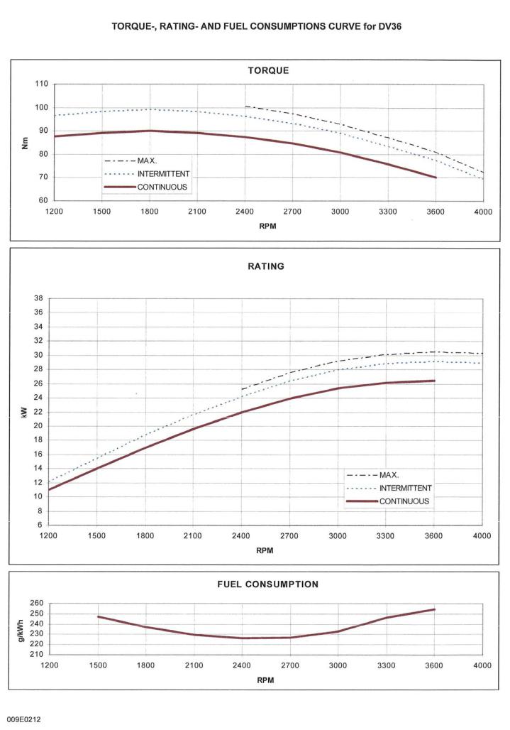
A7
009W2329
A8
Results of Measurement
The below curves indicate results of measurements at 762 mm Hg and a room temperature of 26 °C.
009W2329

A9
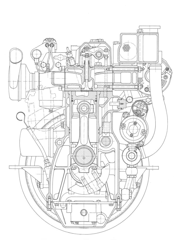
Longitudinal Section of DV36
009W2329
A10
Cross Section of DV36
009W2329

A11
Diagram of the Relation between the Total Weight,
Speed and Horse Power of the boat
The below diagram is normative and not binding in any way as many different circumstances influence the result, especially the type and shape of the boat, the propeller and its placing as well as the horse power of the engine.
Seek the scheme to the right of the intersection between the actual length in the waterline of the ship and the total weight.
Draw a straight line between this point (the intersection) and the fixed point in the bottom left corner.
Where the line of the desired speed crosses the straight line, you can read the required horse power vertically below.
If you know three of the specifications, you can by means of these schemes find the fourth one.
009W2329
B1
SECTION B
LIST OF TOOLS
009W2329-R01
B2
CONTENTS
Tools for repairs on DV36.......................................................... |
page B 3 |
Dimensions of mounting punches ............................................. |
page B 6 |
009W2329-R01
B3
Tools for repairs on DV36
The below mentioned tools are necessary to make the engine repairs described in this manual.
Part of the tools are special tools which can be ordered from the spare parts department at BUKH.
We have indicated the fields of application for the special tools in this manual.
Designation of tools |
Fields of application |
Spare part No. |
|
|
|
Slip-on ring for mounting of |
Section IJ |
|
pistons |
|
|
|
|
|
Puller for cylinder liner |
Section IJ |
009P2235 |
|
|
|
Punch for rear seal ring |
Section G |
009P3177 |
|
|
|
Punch for front seal ring |
Section E |
009P3178 |
|
|
|
Punch for mounting of |
Section M and L |
009P3179 |
camshaft bearing in block |
|
|
|
|
|
Punch for journal for |
Section G |
009P3180 |
intermediate wheel |
|
|
|
|
|
Punch for journal for front and |
Section E and G |
009P3181 |
rear rotating weight |
|
|
|
|
|
Punch for mounting of valve |
Section C |
009P3175 |
guide |
|
|
|
|
|
Punch for mounting of inlet |
Section C |
009P3173 |
valve seat |
|
|
|
|
|
Punch for mounting of exhaust |
Section C |
009P3174 |
valve seat |
|
|
|
|
|
Punch for mounting of expan- |
Section C |
009P3176 |
sion discs in the cylinder head |
|
|
|
|
|
009W2329-R01

B4
Designation of tools |
Fields of application |
Spare part No. |
36 mm socket spanner
19 mm socket spanner for |
Section C |
|
fastening of cylinder head |
|
|
|
|
|
19 mm crowfoot wrench for |
Section C |
009P3225 |
tightening up of cyl. head |
|
|
|
|
|
10 mm Allen top for faste-ning of |
Section L |
|
bearing top section |
|
|
|
|
|
5 mm Allen key |
- |
|
|
|
|
6 mm Allen key |
- |
|
|
|
|
7 mm Allen key |
- |
|
|
|
|
Open-end spanner/ring spanner, |
- |
|
8/10/12/13/14/15/17/19/22/24/27 |
|
|
30 and 32 mm |
|
|
|
|
|
Dismantling tool for valve |
Section C |
009P3115 |
springs |
|
|
|
|
|
Tachometer |
Generally |
009P3106 |
|
|
|
Testing set for fuel nozzles |
Section H |
009P3100 |
|
|
|
Cleaning for fuel nozzles |
Section H |
009P3101 |
|
|
|
Bosch dial indicator for |
Section H |
|
adjustment of fuel pump |
|
|
|
|
|
Bosch dial indicator “holder with |
Section H |
529W0002 |
extension” for adjustment of the |
|
|
fuel pump (KDEP1085) |
|
|
009W2329-R01

B5
Designation of tools |
Fields of application |
Spare part No. |
|
|
|
Flanging tools for nozzle holder |
Section C |
009P2565 |
insert |
|
|
|
|
|
Torque wrench |
Generally |
009P3108 |
(Stahlwille 73/6 1.5-6.5) |
|
|
|
|
|
Torque wrench |
Generally Section C, D, |
009P3109 |
(Stahlwille 73/25 8-26) |
IJ and L |
|
|
|
|
Circlip tongs (external) |
- |
|
A1, 10-28 mm |
|
|
|
|
|
Circlip tongs (internal) |
- |
|
J2, 19-75 mm |
|
|
|
|
|
Puller for gear wheel |
Generally |
|
(Kukko 20/10) |
|
|
|
|
|
Puller for flexible coupling |
Section R |
T 41069 |
|
|
|
Compression gauge |
Section C |
529W0000 |
|
|
|
Adapter for compression gauge |
Section C |
009P3123 |
|
|
|
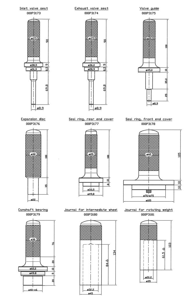
Part of the mentioned special tools can be manufactured without too much trouble at the dealer´s workshopin periods outside the boat season. Therefore we have made sketches at page B6 of each individual mounting punch with dimensions.
Slip-on ring for mounting of pistons is not illustrated but is manufactured of a worn out cylinder liner or another piece of work pipe. Cut the cylinder liner so that you get a piece being about 100 mm high, the turn it conical inside the liner or pipe.
009W2329-R01
B6
C1
SECTION C
CYLINDER HEAD
009W2329-R01
C2
CONTENTS
Exploded view of cylinder head complete ................................. |
page C 3 |
Valve adjustment ...................................................................... |
page C 4 |
Removal and refitment of cylinder head ................................... |
page C 5 |
Replacement of rocker arm or rocker shaft .............................. |
page C 6 |
Adjustment of valve lifter arrangement ..................................... |
page C 6 |
Replacement of rocker arm bushing ......................................... |
page C 7 |
Removal of fuel valves ............................................................. |
page C 8 |
Nozzle holder insert .................................................................. |
page C 9 |
Fitting measures for fuel nozzle insert ...................................... |
page C 10 |
Valve springs............................................................................. |
page C 11 |
Replacement of valve guides .................................................... |
page C 12 |
Pressing-in dimensions for valve guide ..................................... |
page C 13 |
Valve guide stuffing box ............................................................ |
page C 14 |
Repair or replacement of inlet and exhaust valves.................... |
page C 15 |
Exhaust valve ............................................................................ |
page C 16 |
Inlet valve .................................................................................. |
page C 17 |
Grinding of valves...................................................................... |
p age C 18 |
Measures for new valves........................................................... |
p age C 18 |
Replacement of valve seats ..................................................... |
page C 19 |
Cylinder head gasket ................................................................ |
page C 20 |
Air inlet manifold arrangement................................................... |
page C 21 |
Exhaust manifold arrangement.................................................. |
page C 22 |
009W2329-R01
C3
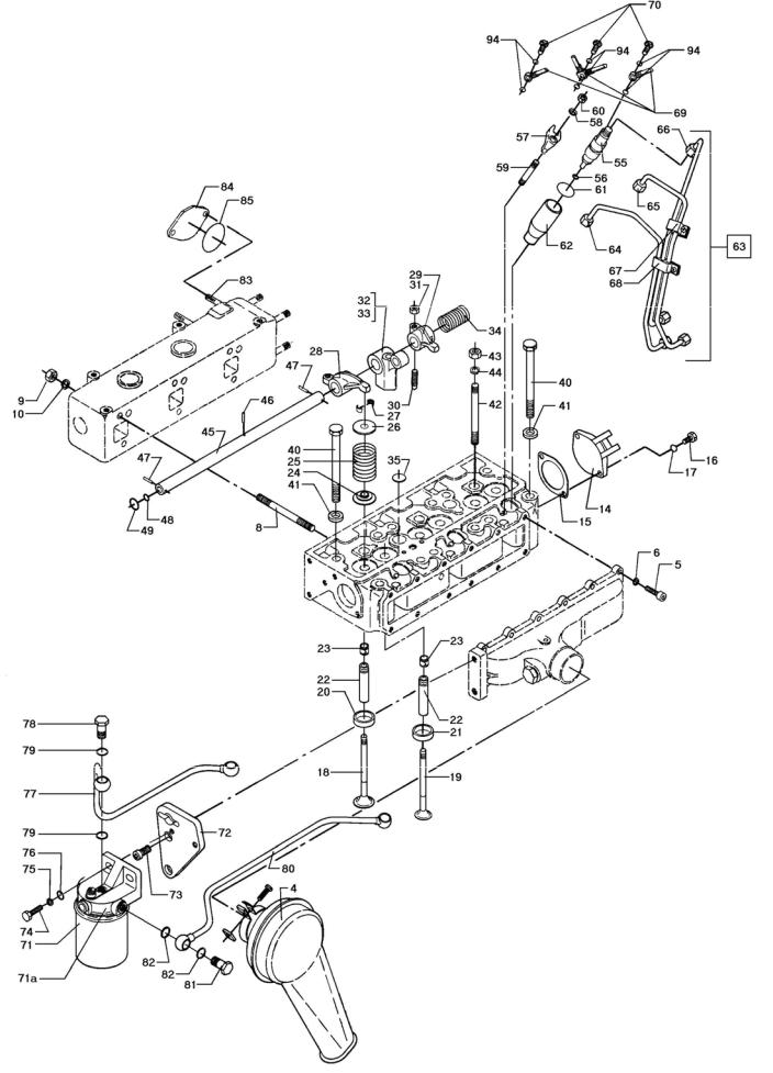
Exploded view of cylinder head
009W2329-R01
C4
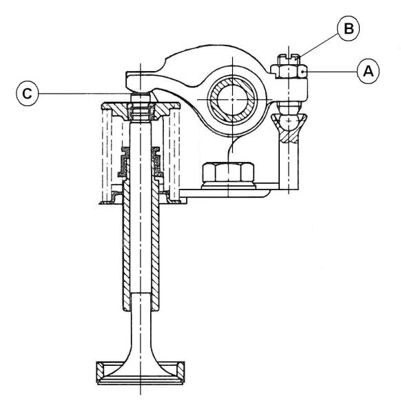
Valve adjustment
The clearance of the inlet and exhaust valves should be adjusted at 0.3 mm when the engine is cold and the clearance of the valves should always be checked after tighteningup of the c ylinder head. The valv es are adjusted when the pisto ns are alternately at their highest point in the working stroke.
Adjust the valves by loosening the counter nut A which makes it possible to adjust the clearance by means of the adjusting screw B.
Measure the clearance with a feeler gauge at C.
009W2329-R01
C5
Removal and refitment of cylinder head
1.Drain off the cooling water.
2.Remove the top cover.
3.Remove valve rocker arms.
4.Remove the inlet and return pipes of the fuel valves.
5.Remove the charging alternator.
6.Remove the exhaust and inlet manifold.
7.Loosen the top bolts, after which the cylinder head can be lifted out of the engine block.
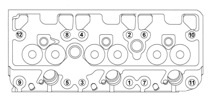
8.Refitment of the cylinder head is made in reverse order and the bolts are tightened evenly at a torque of 118±5 Nm (12±0.5 kpm). Tighten in the order shown on the skeleton diagram below.
009W2329-R01

C6
Replacement of rocker arm or rocker shaft
For each cylinder, a rocker arm column wit htwo rocker arms for inlet valve and exhaust valve, respectively, is fitted on a common shaft with corresponding rocker arm columns and rocker arms for the two other cylinders.
1.Remove the top cover.
2.Unscrew the three central nuts on the rocker arm columns.
3.Lift off the shaft arrangement.
4.Knock out the tube pin and washer in one of the shaft ends.
5.Then the rocker arms and the intermediate springs can be taken out.
Reassembly is a reversal of the dismantling procedure.
Adjustment of valve lifter arrangement
Furthermore, a common shaft for decompression is fitted on the three rocker arm columns.
For a possible removal of the shaft, remove first the pins going down on the rocker arms at decompression, after which the shaft can be pulled out.
When adjusting, adjust the pins so that you faintly see a single groove of the pin thread (about 1.5 mm free pin) just on the side facing the rocker arms.
When fitting the top cover, ensure that the slot in the decompression handle in the top cover mesh with the corresponding pin on the decompression shaft.
009W2329-R01
C7
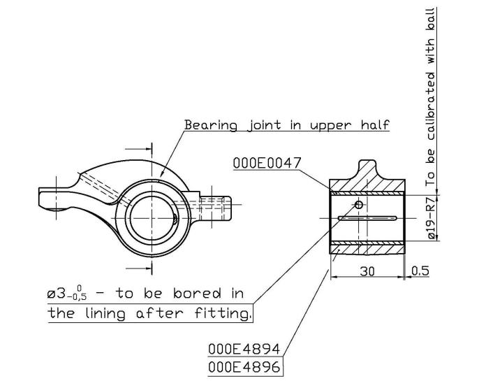
Replacement of rocker arm bushing
1.Remove the rocker arm as indicated on page C5 and check it as to wear and tear as well as fracture.
2.Press out the defective bushing with an adequate tool.
3.Fit the new bushing as shown below paying special attention to the position of the bearing joint and the oil grooves.
4.When fitted, calibrate the bearing bush so that the tolerance ø19-R7 is observed.
Do this either with a calibration ball or with a reamer having the mentioned tolerance.
5.After refitting the rocker arm, check the axial play with a feeler gauge. The axial play may be 0.1 – 0.2 mm.
6.Finish refitting the rocker arm arrangement.
drwg. No. 008E4893
009W2329-R01

C8
Removal of fuel valves
The fuel valves are removed by loosening the clamping nuts for the flanges A as indicated on the sketch below after removal of the inlet and return pipes of the fuel valves.
The drawing at the bottom right-hand side indicates the placing of the fuel valve in proportion to the piston.
For repair of the fuel valves, we refer to section H.
009W2329-R01
C9
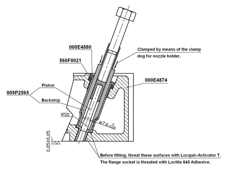
Nozzle holder insert
The nozzle holder inserts are placed in the cylinder head and form – a the name indicates – an insert for the placing of the fuel valves in the cylinder head.
The nozzle holder inserts can be replace d, whic demands that the special tools below for flanging (piston and backstop) are used and that the surfaces are treated as indicated on the drawing.
Remove the old nozz le holder inserts by boring-up the flanged endof the nozzle holder inserts with a ø8 – ø9 mm drill, and then k nockout the nozzle h older inserts with a 10 mm punch.
After having fitted the new nozz le holder inserts, test the cylinder head for pressure with water in order to check the flanged seals.
drwg. No. 008E4881
009W2329-R01
C10
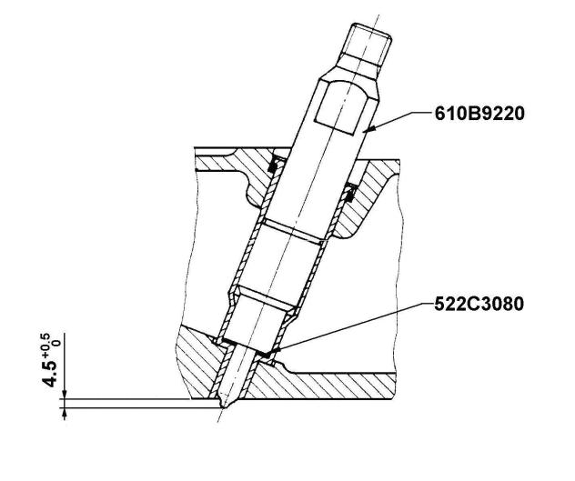
Fitting measurements for the fuel nozzle into insert.
009W2329-R01
 Loading...