

Page 1
OPERATOR´S MANUAL
FOR
BUKH MARINE DIESEL
LIFEBOAT ENGINE
TYPE D4 & D6
BUKH A/S
Aabenraavej 13-17
DK- 6340 Krusaa
Tel: +45 74 62 20 88
Fax: +45 74 62 74 07
E-mail: [email protected]
009U4421-R01 08-03-2017
www.bukh.dk
Page 2

Table of Content
Foreword ...................................................................................................... 4
Safety Information ...................................................................................... 5
Introduction ................................................................................................. 8
Instruments and Controls ........................................................................ 12
Ignition Lock .......................................................................................... 12
e-Key panel .......................................................................................... 12
e-Key Remote ...................................................................................... 13
Control Panels ....................................................................................... 14
Start/Stop Panel ................................................................................... 14
Station Panel ........................................................................................ 14
Cruise Control ...................................................................................... 16
Docking Panel ...................................................................................... 16
Power Trim panel ................................................................................. 17
Gauges ................................................................................................ 18
Displays
Information Display .............................................................................. 19
4" Display ............................................................................................. 21
Glass Cockpit Display .......................................................................... 28
Power Trim ............................................................................................. 30
Trim Ranges ........................................................................................ 30
Trim Controls ....................................................................................... 31
Power Trim Assistant ........................................................................... 32
Trim Instruments .................................................................................. 32
Maneuvering ........................................................................................ 33
Controls ................................................................................................. 35
Side mounted levers ............................................................................ 36
Disengaging the Shift Function ............................................................ 38
Adjusting the friction brake ................................................................... 38
Joystick ................................................................................................ 39
Optional ..................................................................................................... 40
Lowspeed ............................................................................................... 40
Joystick .................................................................................................. 41
Joystick for Docking ............................................................................. 41
High Mode ............................................................................................ 43
High Mode ............................................................................................ 44
Thruster Mode ...................................................................................... 44
Joystick Driving .................................................................................... 46
Autopilot ................................................................................................ 47
Battery Management System ...............................................................
Local Control ........................................................................................ 48
Battery Management display ............................................................... 48
Bukh Interceptor System .......................................................... 52
Operation ............................................................................................. 53
Screen Display ..................................................................................... 54
Cleaning ............................................................................................... 54
Swim platform Interface ....................................................................... 55
Starting ...................................................................................................... 56
Before Starting
................................................................................................. 19
48
...................................................................................... 56
47708085 11-2016 © Bukh 1
Page 3

Starting the Engine ............................................................................... 57
Read the instruments and warm the engine up ................................... 58
Operation ................................................................................................... 59
Reading the Instruments ...................................................................... 59
Alarms .................................................................................................... 59
Maneuvering .......................................................................................... 60
Cruising Speed .................................................................................... 62
Synchronizing Engine Speed ............................................................... 62
Engine Shutdown ...................................................................................... 63
Stop the Engine ..................................................................................... 63
Auxiliary stop ........................................................................................ 64
After Engine Shutdown ........................................................................ 64
Operation Break ................................................................................... 65
Laying Up and Launching .................................................................... 65
Trailering Your Boat ............................................................................. 66
Cold Weather Precautions ................................................................... 66
Fault Handling ........................................................................................... 67
Alarm Handling ........................................................................................ 67
Acknowledge message ........................................................................... 68
Faults List ................................................................................................ 69
Fault Tracing .......................................................................................... 70
Fault Code Register .................................................................................. 71
In Case of Emergency .............................................................................. 78
Running Aground .................................................................................. 78
Starting Using Auxiliary Batteries ....................................................... 79
Emergency Shifting .............................................................................. 80
Emergency Shifting, Drive ................................................................... 80
Emergency Steering ............................................................................. 81
Emergency Alignment, Electrical Rudder Actuator .............................. 81
Emergency steering with control levers ............................................... 84
Emergency Trimming ........................................................................... 85
Start after crash-stop ............................................................................ 85
Maintenance Schedule ............................................................................. 86
Maintenance .............................................................................................. 87
Maintenance Safety Information .......................................................... 90
Engine, General ..................................................................................... 92
Drive Belt, Check and Change ............................................................. 92
Lubrication System ............................................................................... 93
Oil level, checking and topping up ....................................................... 94
Fuel System ........................................................................................... 95
Fuel system, bleeding .......................................................................... 96
Water in Fuel ........................................................................................ 96
Freshwater System ............................................................................... 97
Coolant Level, Checking and Topping Up ........................................... 98
Seawater System ................................................................................... 98
Seawater System, Draining ................................................................. 99
Impeller, Check and Change ............................................................. 100
Seawater System, Cleaning and Inhibiting ........................................ 100
Seawater Filter, Check and Cleaning ................................................ 102
Electrical System ................................................................................ 103
Fuses ................................................................................................. 103
Electrical Connections ....................................................................... 104
2 47708085 11-2016 © Bukh
Page 4

Battery ................................................................................................ 105
Reverse Gear ....................................................................................... 107
Oil level, checking and topping up ..................................................... 107
Drive ..................................................................................................... 108
Transmission lubricant, checking and topping up .............................. 108
Steering ................................................................................................ 109
Hydraulic hoses ................................................................................. 109
Storage ..................................................................................................... 110
Calibration and Settings ......................................................................... 111
Settings Menu ....................................................................................... 111
My View ................................................................................................. 111
Neutral Beep ......................................................................................... 111
Information Beep ................................................................................... 112
Trip Reset .............................................................................................. 112
Depth Alarm .......................................................................................... 112
Display Contrast .................................................................................... 114
Side Selection ....................................................................................... 114
Units ...................................................................................................... 114
Language .............................................................................................. 115
EVC Info ................................................................................................ 115
PTA Calibration ..................................................................................... 116
Fuel Tank .............................................................................................. 117
Speed Factor ......................................................................................... 118
Key Management .................................................................................. 118
Joystick ................................................................................................. 122
Joystick Docking calibration .................................................................. 123
Joystick Inboard Docking calibration ..................................................... 125
Drive Straight calibration ....................................................................... 127
Technical Data ......................................................................................... 128
Viscosity ................................................................................................ 129
Cooling System ................................................................................... 135
Coolant, Mixing .................................................................................. 135
Identification Numbers ....................................................................... 136
Index ......................................................................................................... 139
47708085 11-2016 © Bukh 3
Page 5

Foreword
Welcome!
Congratulations on your new boat equipped with a Bukh marine engine. Bukh engines are designed to fulfill
Bukh’s core values; quality, safety and environmental care. And after more than 100 years as an engine
manufacturer, the Bukh brand has also become a symbol of reliability, technical innovation, top-of-the-range
performance and long service life. Bukh marine engines are used all over the world, in all possible operating
conditions for professional as well as leisure purposes.
Make sure to thoroughly read through this Operator’s Manual and take necessary actions regarding running and
maintenance before your maiden voyage. It contains the information you need to be able to operate and maintain
the engine safely and correctly. Pay careful attention to the safety instructions included in the manual.
As the owner of a Bukh marine engine, you become part of a worldwide network of dealers and service
workshops that assist you with technical advice, service requirements and replacement parts. Contact your
nearest authorized Bukh dealer for assistance.
Information about your closest Bukh dealer and other useful information can be found at
www.bukh.dk
4
47708085 11-2016 © Bukh
Page 6
Safety Information
!
Read this chapter very carefully. It concerns your safety. This chapter describes how safety information is
presented
rules for using and looking after the engine.
in the operator’s manual and on the product. It also provides you with an introduction to the basic safety
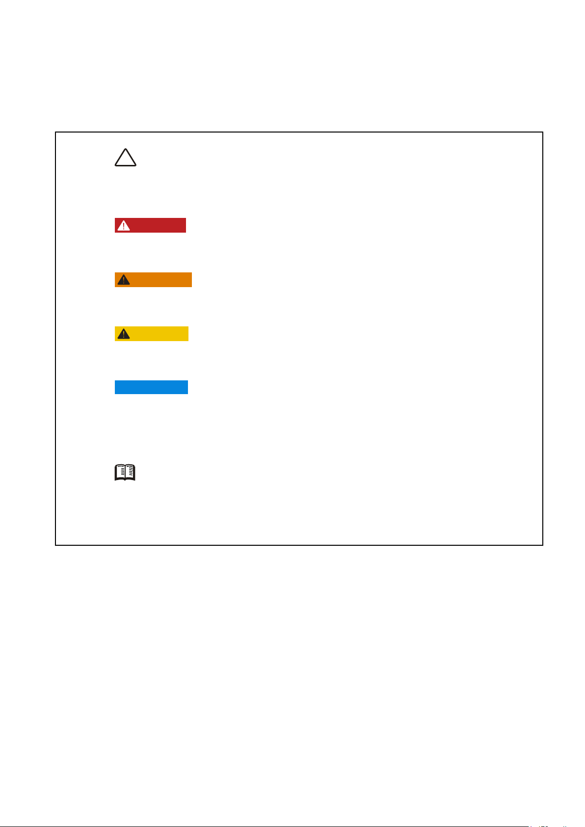
This symbol is used in the operator’s manual and on the product to call your attention
to the fact that this is safety information. Always read such information very carefully.
Safety texts in the operator’s manual have the following order of priority:
DANGER!
Indicates a hazardous situation which, if not avoided, will result in death or serious
injury.
WARNING!
Indicates a hazardous situation which, if not avoided, could result in death or serious
personal injury.
CAUTION!
Indicates a hazardous situation which, if not avoided, could result in minor or moderate
personal injury.
IMPORTANT:
Indicates a situation which, if not avoided, could result in property damage.
NOTICE! Used to draw attention to important information that will facilitate work or
operations.
In some cases, this symbol is used on our products and refers to important information
in the operator’s manual. Make sure that warning and information symbols on the
engine are clearly visible and legible. Replace symbols that have been damaged or
have been painted over.
47708085 11-2016 © Bukh 5
Page 7

Safety Information
Daily Checks
Make a habit of giving the engine and engine bay a
visual check before driving (before starting the
engine) and after operation (when you have stopped
the engine). This will help you to quickly discover
whether
other abnormal event has occurred, or is about to
occur.
there is any leakage of fuel, coolant, oil or any
WARNING!
Do not start the engine if there is reason to suspect
fuel and/or propane leaks, or if there is explosive
material nearby.
Maneuvering
To avoid passengers falling overboard, refrain from
extreme and sudden rudder movements and ahead/
astern movements.
A rotating propeller can cause severe injuries. Make
sure
that there is nobody in the water before engaging
ahead/astern drive. Never drive close to bathers or in
areas where it can be expected that people are in the
water.
Fuel Filling
There is always a risk of fire and explosion during
fueling.
stopped during fueling.
Never overfill the tank. Close the fuel filler cap
securely.
Only use fuel recommended in the Technical
Data, page 130. The wrong grade of fuel can cause
serious malfunctions, power loss or stop the engine.
In diesel engines, fuel of poor quality can cause
damage to the fuel system or cause the engine to
over-speed, with risk of personal injury.
Smoking is forbidden and the engine must be
Accidents at Sea
Maritime rescue statistics show that a large number
of boat accidents are caused by inadequate engine
and boat maintenance and the lack of safety
equipment.
Make sure that the boat engine is properly maintained
by making sure that the recommended service is
performed, and that necessary safety equipment is
available and functional.
Lanyard Switch
We recommend installing and using a lanyard switch
(optional), especially if the boat is capable of high
speeds. The lanyard switch stops the engine if the
driver looses control of the boat.
6 47708085 11-2016 © Bukh
Page 8
Carbon Monoxide Poisoning
P0003073
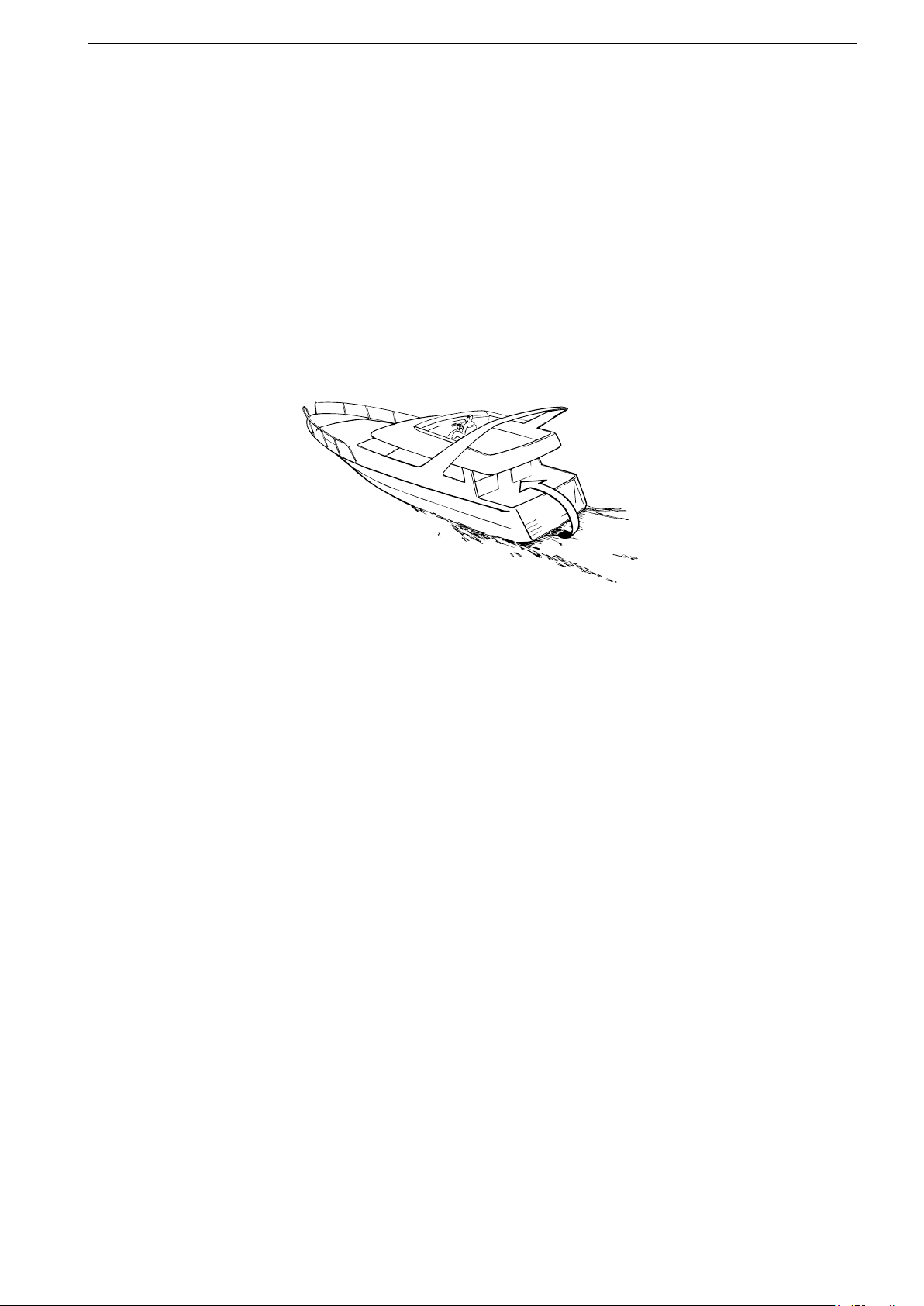
When the boat moves forward, an area of lower
pressure air is formed behind the boat — so-called
turbulence. In certain conditions, this turbulence can
be powerful enough to draw the exhaust fumes into
the cockpit or cabin, creating a risk of carbon
monoxide poisoning to people on board.
The turbulence problem is most pronounced on tall,
broad-beamed boats with a transom stern. But even
for other boat types, low-pressure suction can be a
problem in certain conditions, such as driving with
cockpit awnings rigged. Other factors that can
increase
load distribution, swell, trim, open hatches and
ventilators etc.
the effect of turbulence are wind conditions,
Safety Information
Most modern boats are, however, designed so that
the problem of low-pressure suction is very rare.
Should turbulence nevertheless occur, hatches or
ventilators must not be opened since this might
exacerbate the problem. Instead, try to change the
speed, trim or load distribution. If possible, take down
or open the cockpit awning. Contact your boat dealer
for the best solution for your boat.
Remember
The list below includes some tips on what to remember to bring on any boat trip. The list can be extended since
the need for safety equipment varies with the boat type and where or how it is used etc. We recommend you
ask a regional boat or sea safety organization for more detailed maritime safety information.
Safety Equipment:
life jackets
•
• communication equipment
• emergency rockets
• approved fire extinguisher
• first aid kit
• life buoy
• anchor
• paddle
• flashlights
• Take your chart out and study your planned route. Calculate distance and fuel consumption. Listen to
weather reports.
• Tell your friends/relatives about route plans if you undertake a long journey. Remember to notify changed
plans or delays.
• Inform everybody aboard about where the safety equipment is located, and how it works. Make sure that
there is more than one person aboard who can start and operate the boat safely.
Spare Parts and Tools:
• impeller
• fuel filters
• fuses
• tape
• hose clamps
• engine oil
• other tools that may be required
47708085 11-2016 © Bukh 7
Page 9

Introduction
Check that you heave received the correct operator’s manual before continuing reading. If not, please
contact your Bukh dealer.
For engine designations, refer to Technical Data, page 128. The designation is stated on the engine plate, refer
to Technical Data, page 136.
About this manual
This Operator's Manual has been prepared to give
you the greatest possible benefit from your Bukh
marine engine. It contains necessary information
regarding safe and correct engine operation and
maintenance. Read the Operator's Manual carefully
and learn to handle the engine, controls and other
equipment in a safe manner before you cast off on
your maiden voyage.
Always have the Operator's Manual available. Store
it safely and do not forget to hand it over to the next
owner if you sell your boat.
The Operator’s Manual describes the engine and
equipment sold by Bukh. The illustrations in this
book may cover several product types, which means
that there may be slight differences between the
illustrations and the purchased product. This does,
however, not affect the validity of the information
and/or instructions in the manual. Bukh reserves the
right to make alterations to specifications, design
features, and illustrations without prior notice.
Warranty
Your new Bukh marine engine is covered by a limited
warranty, subject to the conditions compiled in the
6.4-F2 Rev. 30.05.11 General Terms of Sale and
Delivery
Read the information carefully, the information can
be found on www.bukh.dk
Environmental Care
Bukh has special responsibility as an engine
manufacturer, and for this reason environmental care
is a natural cornerstone of our product development.
Bukh currently has a broad engine program in which
great advances have been made in reducing
exhaust emissions, fuel consumption and engine
noise etc. We hope that you will be keen to preserve
these qualities. Always follow the directions in the
Operator's Manual regarding fuel grades, operation
and maintenance to avoid unnecessary
environmental impact. Contact your Bukh dealer if
you notice any changes such as increased fuel
consumption or increased exhaust smoke.
Your New Boat
Carefully read through the instructions and other
information that is delivered with the new boat. Learn
to handle the engine, controls and other equipment in
a safe and proper manner. If this is your first boat or
if the boat type is unfamiliar to you, we recommend
that you practice maneuvering the boat before casting
off on the maiden voyage. Make yourself familiar with
the boat's seakeeping and maneuvering qualities at
different speeds, sea states and load conditions.
Bear in mind that a person in charge of a boat under
way bears the legal responsibility of knowing and
following the regulations for passage and safety
afloat. Learn which regulations apply to you and your
waters by contacting the relevant authorities or
maritime safety organization. We recommend that
you complete a boat driver’s course.
Remember always to hand in environmentally
hazardous waste such as drained oil, coolant, old
batteries, etc. for treatment at a recycling facility.
Our united efforts can make a valuable contribution to
the environment.
8 47708085 11-2016 © Bukh
Page 10

Introduction
Running In
The engine must be run in during the first 10 hours of
operation. Do this by using the engine in normal
operation, where full load is only applied for short
periods of time. Never run the engine at constant
speed for any longer periods of time.
Since oil consumption is higher during the running in
period, be sure to control the oil level more frequently
than normally recommended.
Refer to Maintenance, page 87 for more
information.
Fuel, Oils and Coolant
Only use the fuels and oils recommended in the
Technical Data, page 129, since other grades may
cause malfunctions, increased fuel consumption, and
possibly shorten the life of the engine.
Always change the oil, oil filters, and fuel filter at the
specified maintenance intervals.
Make sure to always use suitable and correctly mixed
coolant.
Future warranty claims related to engine and
accessories may be denied if an unsuitable coolant
has been used, or if the instructions for coolant
mixture have not been followed.
Maintenance and replacement parts
Bukh engines are designed for maximum reliability
and long life. They are not only built to withstand a
demanding environment, but also to have the
smallest possible environmental impact. These
qualities will be maintained through regular servicing
and the use of spare parts with the same quality as
Bukh original spare parts. If reliable and purpose-
built parts are not used, your safety, health, and the
machine's function may be compromised. Bukh has
a world-wide network of authorized dealers.
They are Bukh product specialists, and have the
accessories, genuine parts, test equipment and
special tools needed for high quality service and
repair work. Always observe the maintenance
intervals in the manual, the complete Service Protocol
can be found at volvopenta.com. Remember to note
the engine / transmission identification number when
you order service and spare parts.
Excessive Strain On a Product and
Components
Bukh products and their components are not
dimensioned for external loads. Never stand or step
onto an engine, transmission or its components.
Loads can bring about damage and the malfunction
of a product or property.
47708085 11-2016 © Bukh 9
Page 11
Instruments and Controls
IGNITION IGNITION
START/STOP START/STOP
P0016313
This chapter describes the instruments, panels and controls Bukh sells for your engine.
If you would like to complement your instrumentation, or if your boat is equipped with instruments not described
here, we ask that you contact your Bukh dealer.
Ignition Lock
There is always a helm station with an e-Key panel on
a boat. The ignition must be switched on here in order
to use other helm stations.
Read the starting instructions in Starting, page 56 to
make sure you use the correct start procedure.
e-Key panel
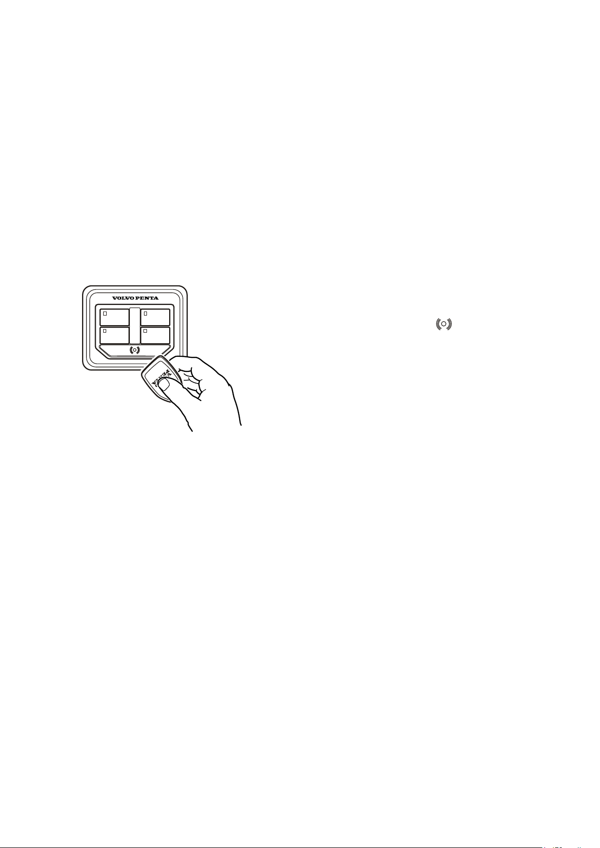
The Bukh e-Key consists of a panel and a key fob.
Hold the key fob in front of the symbol on the panel
to unlock the EVC system. A sound confirms the
system is unlocked.
When the electrical system is locked, a red light will
flash under the symbol. The lamp goes out to indicate
the system is unlocked.
Key Management
Two key fobs are provided at the time of delivery. It is
possible to add additional keys; the system allows up
to four keys. With a key already registered to the
system other keys can be added or removed, see Key
Management, page 118.
Safety Lanyard
A safety lanyard (optional extra) can be connected to
the panel. Should the safety lanyard be removed, the
engines will stop, the system alerts and a warning
message will be displayed in the Information Panel.
12 47708085 11-2016 © Bukh
Page 12
ON OFF
1 2
P0015214
P0016498
Instruments and Controls
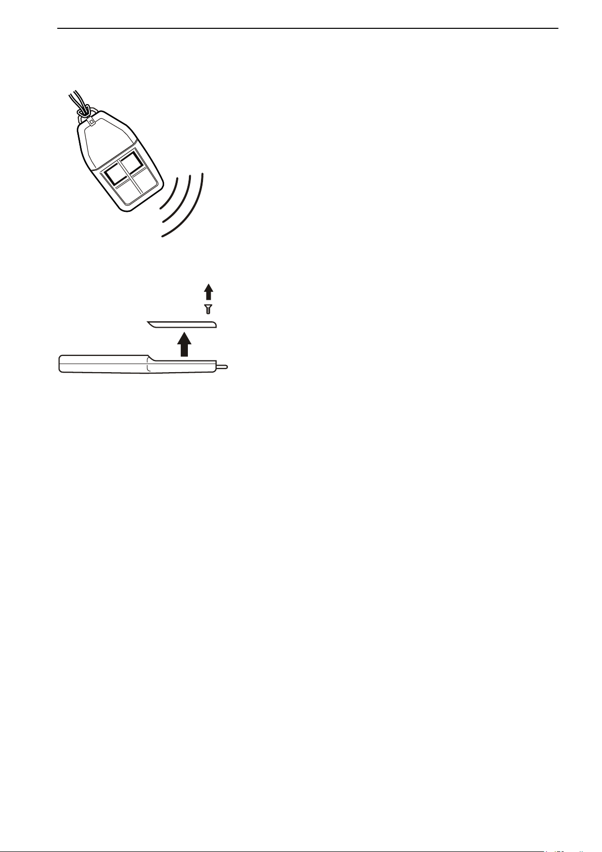
e-Key Remote
e-Key Remote Sender locks and unlocks the boat's
electrical
e-Key Remote Receiver.
On the key there are also two buttons that control
relays to optional functions such as deck light or anchor
winches.
ON – turns on the start switch and other selected
switches.
OFF – turns off the start switch and other selected
switches.
1 and 2 – the buttons are used to turn optional boat
functions off and on.
Battery replacement
Undo the screw on the battery cover and replace the
battery. Battery types: CR2032.
system and starts the engine's ignition via the
Battery installation
Place the battery cover back fasteners and secure the
gasket by pressing on the cover. Install the screw to
secure the cover placement.
NOTICE! The e-Key remote can still be used as a
regular key fob even if the battery is discharged, refer
to e-Key panel, page 12.
47708085 11-2016 © Bukh 13
Page 13
P0012495
Instruments and Controls
Control Panels
Bukh control panels can be installed in different
combinations. The panels all look the same but are
configured to handle different functionality. The
number of available panels and their function depend
on the boat’s functionality setup.
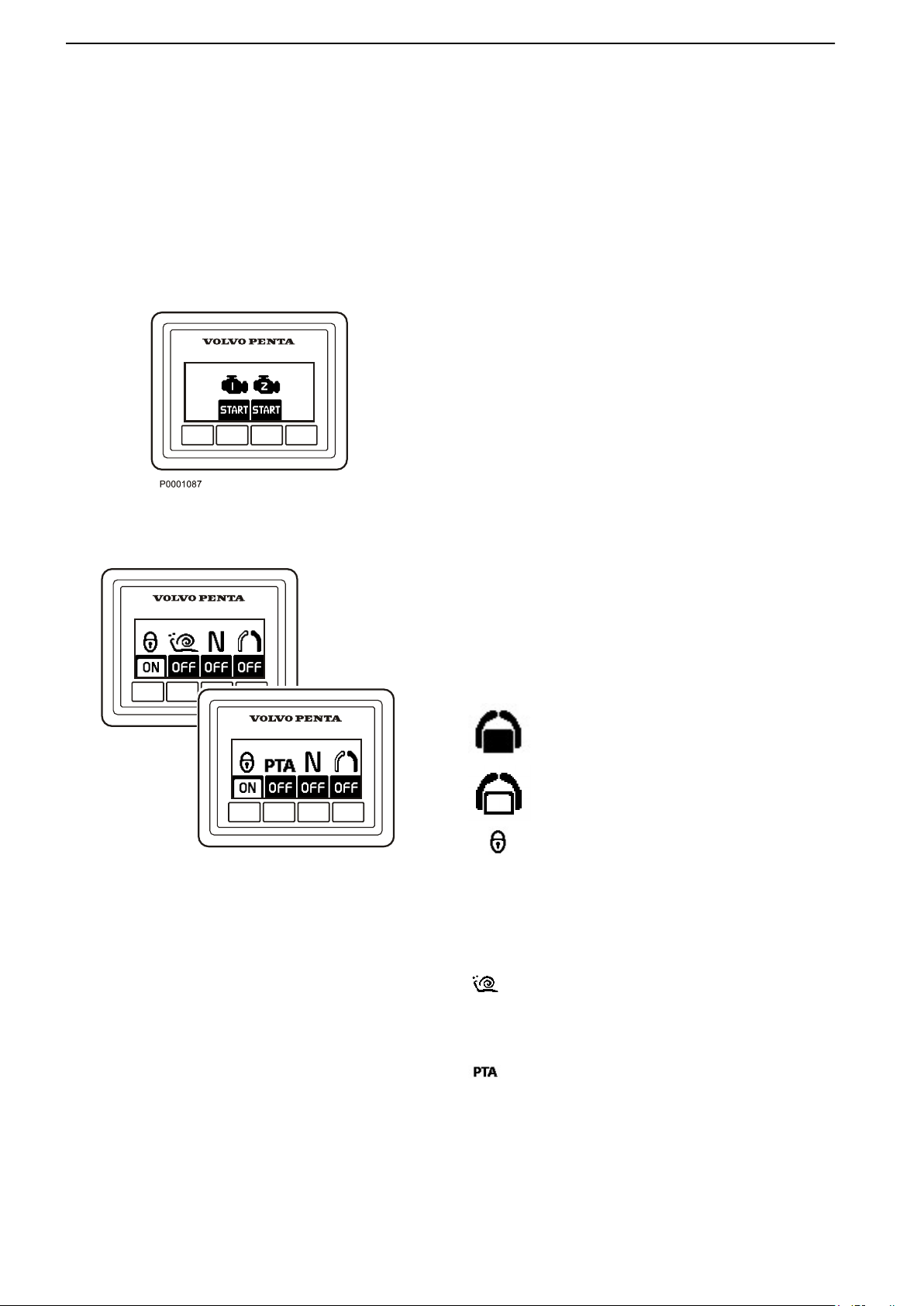
Start/Stop Panel
The Start/Stop panel is used for starting and stopping
the engine.
To start the engine, the ignition must be switched on
at the main helm station.
Read the starting instructions in the chapter
Starting, page 56 to make sure the correct start
procedure is used.
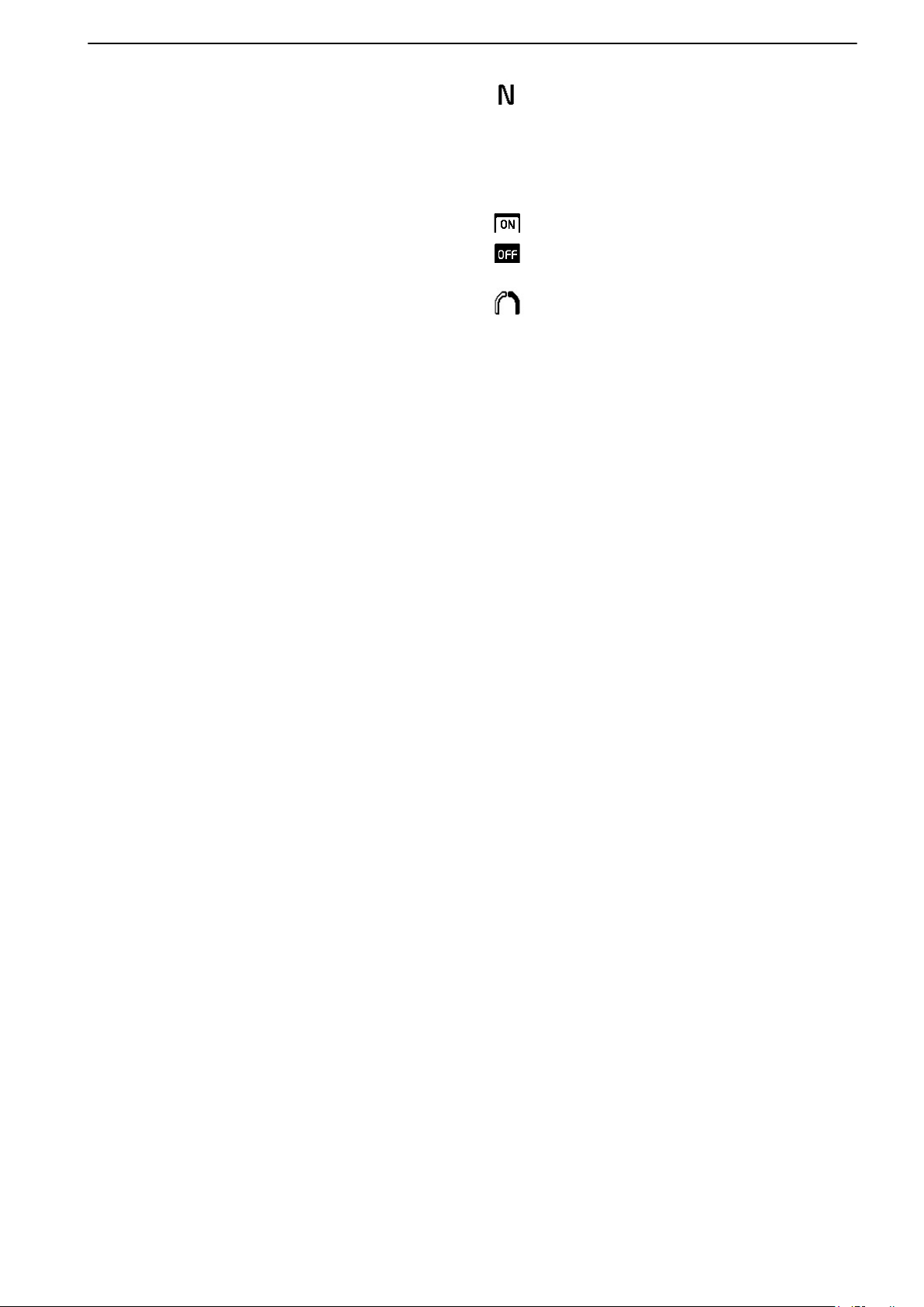
Station Panel
Activation
Activate the helm station with a single press of the
button.
Further pressure locks the helm station.
To render the helm station inactive, hold the button
down for 3 seconds.
Inactive helm station
Active helm station
Locked helm station
Lowspeed and Power Trim Assistant (PTA)
Depending on the installation the optional functions
lowspeed or Power Trim Assistant are engaged with
the button.
Lowspeed
For further information about the function, refer to
Optional, page 40
Power Trim Assistant (PTA)
For further information about the function, refer to
Instruments and Controls, page 30
14 47708085 11-2016 © Bukh
.
.
Page 14
Instruments and Controls
Neutral button
gearshift function can be disconnected so that the
The
control lever only operates the throttle. The neutral
button disengages the drive/reverse gear so that
engine speed may be increased without driving the
boat; (warm-up mode).
The drive is disengaged.
Drive engaged for movement ahead/astern.
Single lever
When the single-lever function is activated, the lever
that is moved from its position first becomes the control
lever for both engines. The other control lever has no
function as long as the single-lever function is
activated.
In order to activate the single-lever function, the control
levers must in be roughly the same position, max 10%
difference.
47708085 11-2016 © Bukh 15
Page 15
P0001259
Instruments and Controls
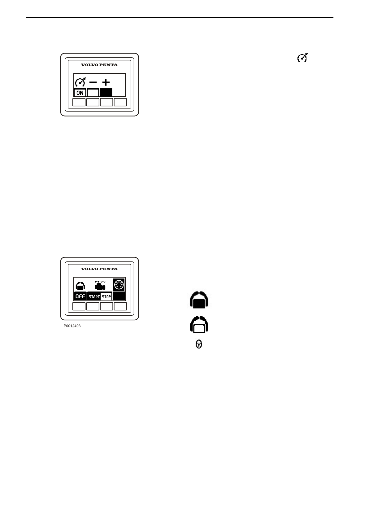
Cruise Control
Switch on cruise control by pressing the button.
Make fine adjustments to the locked engine speed by
pressing the + or – buttons to increase or reduce the
speed.
Docking Panel
When the boat is operated from a docking station,
engines can be stopped and started and messages
can be managed using the docking panel.
The joystick can be used for maneuvering when the
docking station is activated; refer to the Instruments
and Controls, page
35 section for further information.
Activation
Activate the helm station by depressing the on/off
button. Further pressure on the button locks the helm
station.
To switch off the function, hold the button down for 3
seconds.
Twin installation
Both engines in a twin installation must be running
before the docking station can be activated.
The helm station is inactive.
The helm station is active and the docking
function is switched on.
The helm station is locked.
Start/Stop
the STOP and START buttons to stop and start
Press
all engines.
The circles above the engine symbols show which
engines are running. An empty circle means an engine
is running.
16 47708085 11-2016 © Bukh
Page 16
P0001308
Instruments and Controls
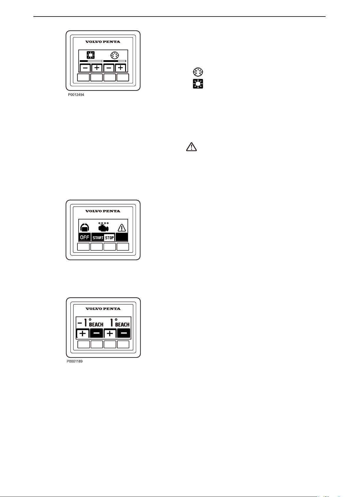
Contrast and backlighting
The button on the far right is used to adjust contrast
and panel backlighting. The button is also used to
confirm fault messages.
Backlighting
Contrast
Press the button to adjust the contrast and the
backlighting.
Use + and – to increase or reduce the contrast or
backlighting.
Adjustments affect all screens in the system.
Fault message
is displayed on the screen when the system
discovers a fault.
All fault messages must be acknowledged.
Acknowledge by pressing the button; if the fault is
accompanied by an audible signal, the signal will be
silenced. Go to the information display to obtain
information regarding the alarm.
Contact a Bukh workshop for a complete readout of
all fault messages.
For further information on how to handle fault
messages and recommended actions, refer to the
Fault Handling, page 67 and Fault Code
Register, page 71 chapters.
Power Trim panel
The Power Trim panel allows you to adjust the angle
of the drive with respect to the transom.
For twin engine installations, the control panel can be
used to make individual or simultaneous adjustments
to the drives.
By trimming out the drive away from the transom, the
bow will be ”raised” in relation to the horizontal axis and
trimming in the drive will ”lower” the bow of the boat
+ Will trim the drive away from the transom, the bow
will be ”raised” in relation to the horizontal axis.
– Will trim the drive away towards the transom, ”lower”
the bow of the boat.
For further information on Power Trim refer to
Instruments and Controls, page 30.
47708085 11-2016 © Bukh 17
Page 17
0
3
2
1
4
RPMX1000
P0012490
351
h
Instruments and Controls
Gauges
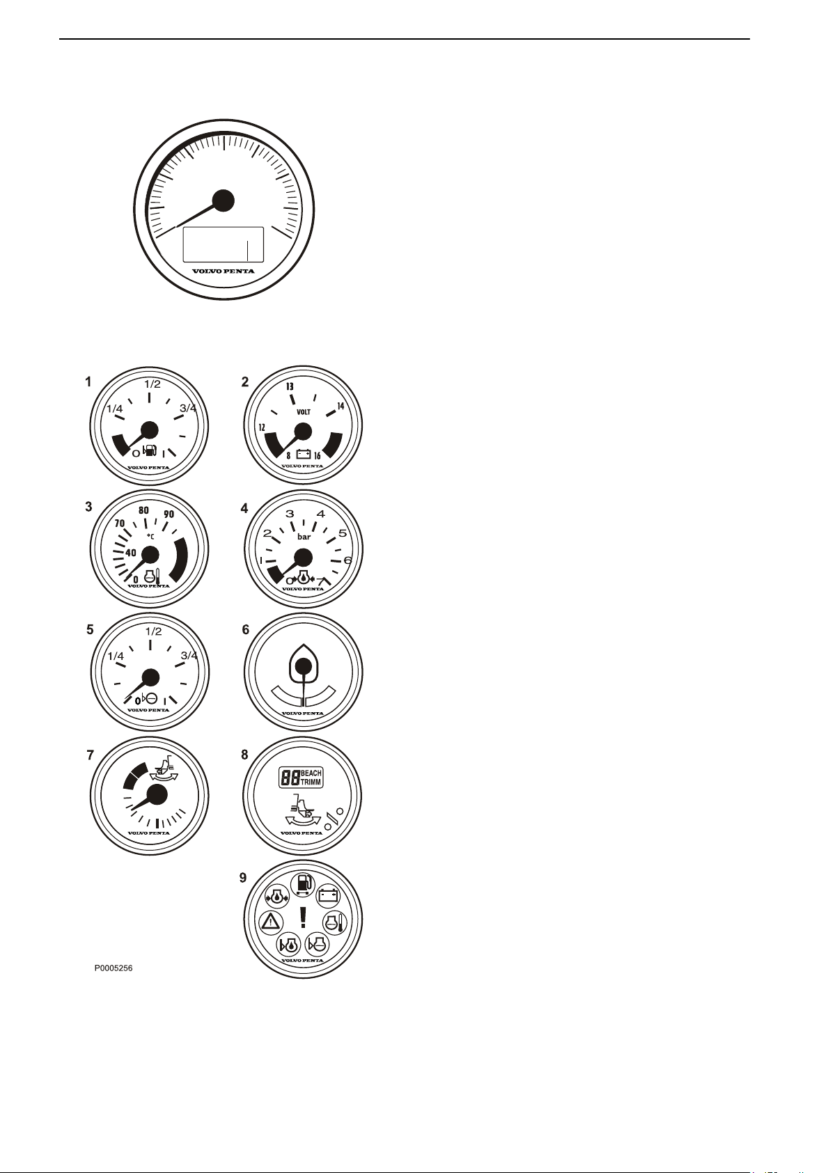
These instruments are sold as engine options by Bukh.
Tachometer
The tachometer displays engine speed; multiply the
value shown on the dial by 1,000 to get the number of
engine revolutions per minute.
Engine hours are displayed in the tachometer window.
When a function is activated a symbol is shown briefly
on the display.
1 Fuel level gauge
The fuel level gauge shows the quantity of
remaining fuel.
2 Voltmeter, battery charging
The meter shows the alternator charge current.
During operations the charge voltage should be
around 14 V. When the engine is stopped and
electrical power switched on the battery voltage
should be around 12 V.
If a 24 V system is installed, the charge voltage
should be around 28 V during operations.
3 Coolant temperature gauge
The instrument shows engine coolant temperature.
During operations coolant temperature should
normally be between 75-95°C (167-203°F).
4 Oil pressure gauge
The oil pressure gauge displays engine oil
pressure. During operations the oil pressure gauge
should normally show 3-5 bar. At idle, lower values
are normal.
5 Fresh water level sensor
Freshwater tank level gauge.
6 Rudder position indicator
The instrument shows rudder position.
7 Trim indicator, analog, for Aquamatic engines
The analog indicator shows the position of the stern
drive in relation to the transom shield.
8 Trim indicator, digital, for Aquamatic engines
The digital indicator shows the position of the stern
drive in relation to the transom shield.
9 Alarm monitor
The alarm monitor gives a visual warning to call
attention to any alarms that occur.
18 47708085 11-2016 © Bukh
Page 18
P0001306
Instruments and Controls
Displays
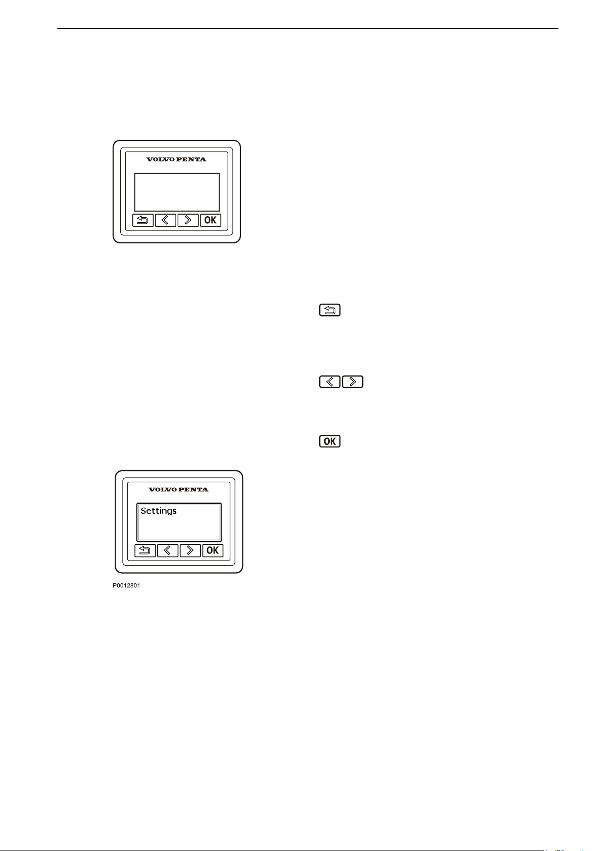
Information Display
The
information display shows engine and operational
information, messages and alarms.
There is one information display per driveline and helm
station if no 7" or larger screen is installed.
The information shown can be set up according to
personal preferences. The basic settings show:
Engine speed
•
Oil pressure
•
Coolant temp
•
Battery voltage
•
Press this button to return to the previous menu.
To navigate back to the main menu, hold the button
for more than three seconds or press the button
down
repeatedly.
Press these buttons to navigate backwards and
forwards in the menus.
Hold down a button to scroll through a menu.
Press this button to confirm a selection.
Settings
Browse
to proceed to the submenu.
For further information about settings, refer to Settings
Menu, page 111.
to the settings menu and press the OK button
47708085 11-2016 © Bukh 19
Page 19
Instruments and Controls
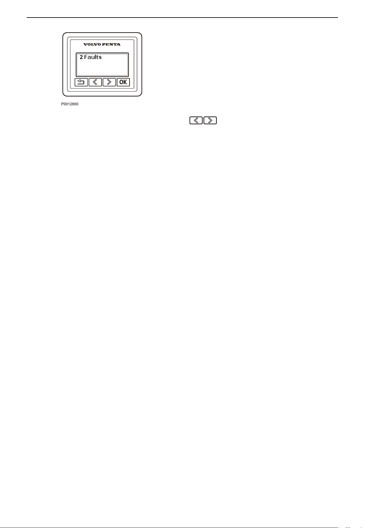
Fault Messages
If
the system discovers a fault, the word Fault and the
number of discovered faults, are shown on the display.
To see the what faults have been detected, press the
OK button.
For further information on how to handle fault
messages and recommended actions, refer to Fault
Handling, page 67.
Backlighting
Display backlighting can be adjusted by pressing the
buttons simultaneously.
20 47708085 11-2016 © Bukh
Page 20
P0001101
Instruments and Controls
4" Display
The 4” display is an optional supplement to the Bukh
control system. Via the display it is possible to view
and control all installed functions in the system.
IMPORTANT:
Prolonged exposure to strong sunlight may damage
the screen and cause functional faults.
Make a habit of protecting the screen by using the
protective cover when the boat is not in use.
The Bukh 4" screen is controlled using the panel
buttons as follows:
Return to the previous menu.
Adjust display contrast. If contrast changes are
not confirmed, display contrast will automatically
revert to its former state shortly after the button is
released.
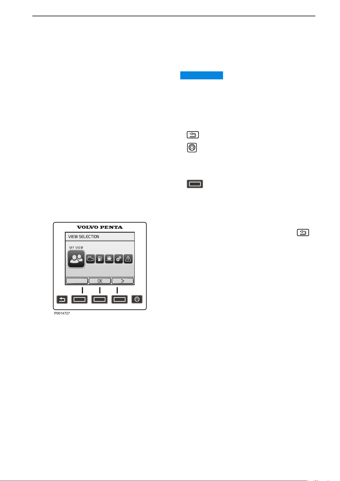
View Selection
The button functions are shown on the
display. Navigate
by pressing the appropriate button.
back or forth or confirm a selection
View Selection
When starting up the system, the last selected view is
shown. To return to the main menu, press the
button. Use the arrow buttons to navigate to the
desired screen.
The following screens are available in the 4” display:
My View shows operating information.
•
Engine View shows engine information.
•
Fuel Economy shows the trip computer.
•
Vessel shows information regarding the boat
•
installation
Settings shows display settings and installed
•
functions.
Warning Manager shows detected faults and their
•
corrective actions.
Battery View shows battery information.
•
47708085 11-2016 © Bukh 21
Page 21
Instruments and Controls
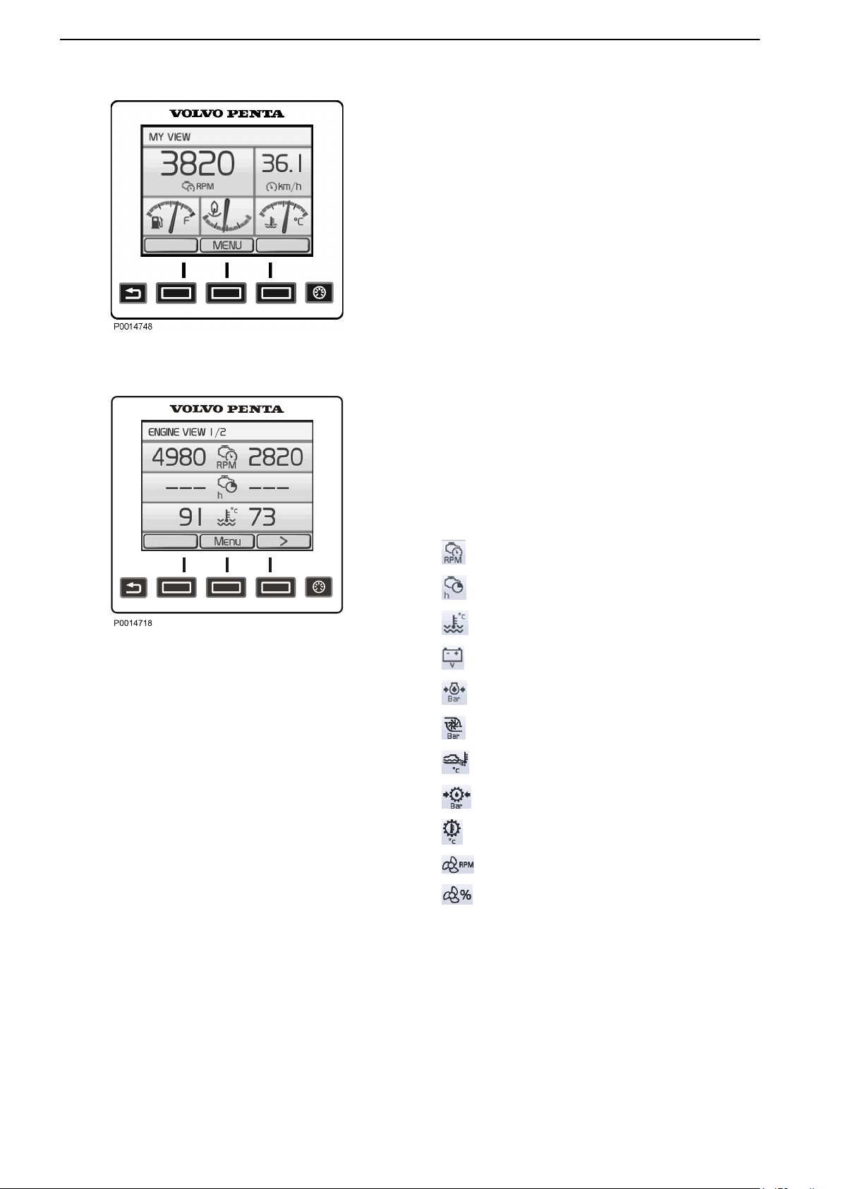
My View
My View
Gauge and operations information is shown in the My
View window.
Some functions are preset as quick selections. These
can be switched on/off by pressing the OK button.
To change the gauge and information shown, refer to
the part in this chapter entitled Replace Gauge.
Engine View
The view shows information about the engine and
engine transmission. The information is displayed on
screens. Use the arrow buttons to toggle between
two
the screens. Refer the part in this chapter entitled
Replace Gauge for information on how to change
settings for the displayed information.
Depending on the functions installed in the boat, the
following can be displayed:
Engine View
Engine Speed
Engine Hours
Engine Coolant Temperature
Battery Voltage
Engine Oil Pressure
Turbo Pressure
Exhaust Temperature
Transmission Oil Pressure
Transmission Oil Temperature
Propeller Rotation
Ahead Speed
22 47708085 11-2016 © Bukh
Page 22
Fuel
Instruments and Controls
Current Fuel
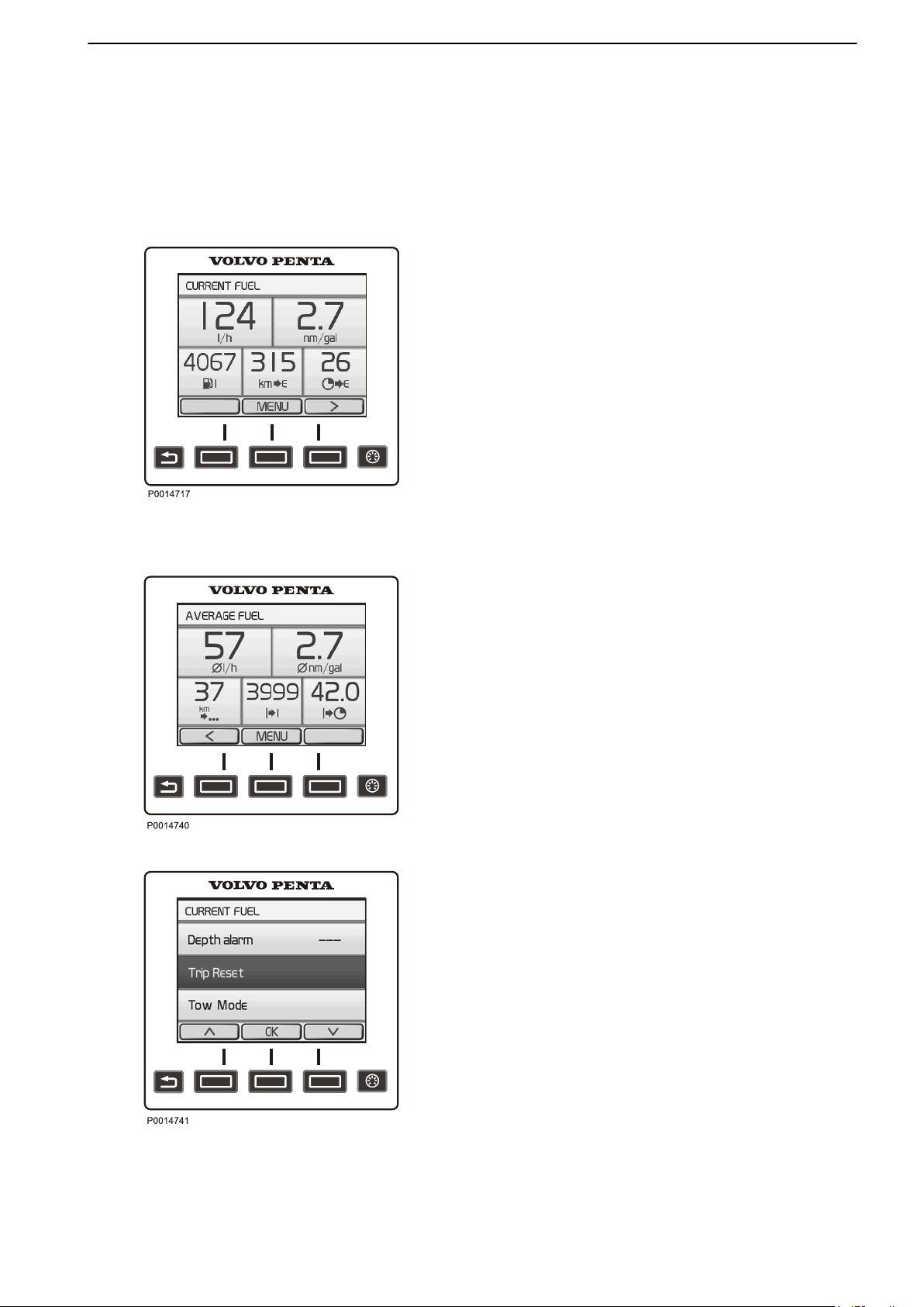
The Fuel
screens; Current Fuel and Average Fuel. Use the
arrow buttons to toggle between the screens.
The Current Fuel screen displays the following
parameters:
Instant Fuel Rate shows the current fuel
•
consumption per hour.
Instant Fuel Economy is based on the current fuel
•
consumption.
Remaining In Tank shows the amount of fuel left in
•
the tank.
Distance Remaining is based on the current fuel
•
consumption and shows trip distance with remaining
fuel.
Time To Empty is based on current fuel
•
consumption and shows the remaining operating
time.
The Average Fuel screen displays the following
parameters:
view displays the trip computer in two
Average Fuel
Average Fuel Rate shows the average fuel
•
consumption per hour since last trip computer reset.
Average Fuel Economy is based on the average
•
fuel consumption since last trip computer reset.
Trip Distance shows the distance travelled since
•
the latest trip computer reset.
Trip Fuel shows the fuel consumption since the
•
latest trip computer reset.
Trip Hours shows the time travelled since last trip
•
computer reset.
Trip Computer Reset
To reset all trip computer parameters, press the Menu
button and select Trip Reset.
Trip Computer Reset
47708085 11-2016 © Bukh 23
Page 23
Instruments and Controls
Vessel
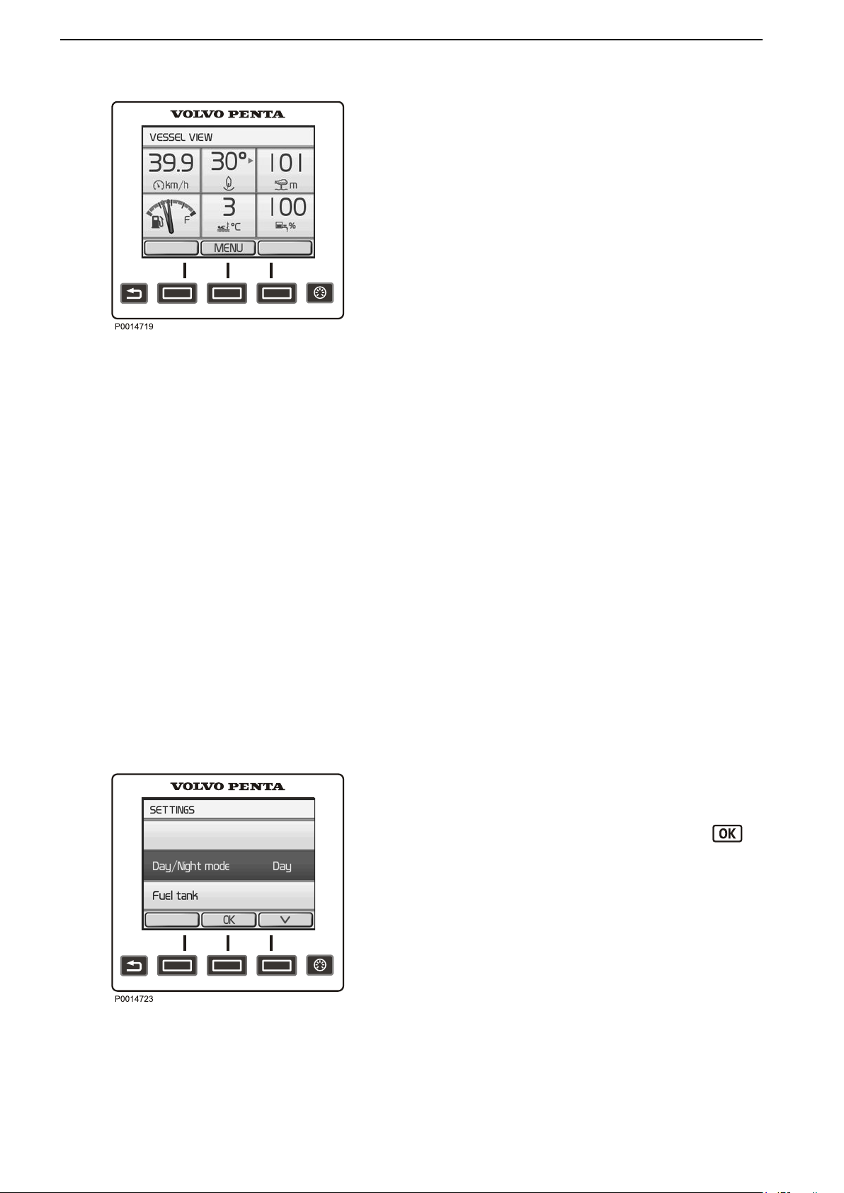
Vessel
The view displays the boat’s installation information.
See the part in this chapter entitled Replace Gauge
for information on how to change settings for the
displayed information.
Depending on the functions installed, the following
parameters can be displayed:
Boat Speed
•
Rudder Angle
•
Depth
•
Refer to Depth Alarm, page 112 for information
about echo sounder settings.
Fuel Level
•
Sea Water Temperature
•
Freshwater Level
•
Interceptor Position
•
Refer to Optional, page
Interceptor Position.
52 for information about
Battery view
The Battery View shows the battery status for the
batteries. Use the arrows to toggle between the
different battery groups. Depending on the functions
installed, the following parameters can be displayed:
SOC (State of Charge)
•
Time to Empty / Time to Full
•
Voltage
•
Current
•
Battery Health
•
Settings
Display settings and various system function settings
are dealt with in the Settings menu. The information
shown varies depending on the installation.
Navigate to the desired setting and press the
button to reach the submenu.
Key Management
To add and remove keys to/from the system, refer to
Key Management, page 118.
Day/Night Mode
Day mode shows dark colored text against a light
colored background and Night mode shows light
Settings
24 47708085 11-2016 © Bukh
colored text against a dark colored background.
Fuel Tank
Fuel tank calibration and settings. For information
regarding calibration, refer to Fuel Tank, page 117.
Page 24

Instruments and Controls
Neutral Beep
Enable
is in neutral position.
Info Beep
Enable or disable the signal confirming function
activation and deactivation.
Info Beep Level
Set the volume of the Info Beep.
Trip Reset
Reset all trip computer data.
Depth Alarm
Set the depth alarm function. Refer to Depth
Alarm, page 112 for information on how to turn the
function on or off and set the alarm limits.
Display Contrast
Set the display contrast for all displays.
or disable the signal indicating when the control
Display Type
Define for which engines information shall be
displayed.
Units
Set the unit settings for the system (metric, US or
Imperial).
Language
Set the system language.
Speed Factor
If the speedometer is showing incorrect values, it is
possible to correct this by adjusting the Speed
Factor.
Refer to Speed Factor, page 118 for more information.
EVC Information
Shows information about components, software, and
functions. Installed functions are check marked.
47708085 11-2016 © Bukh 25
Page 25
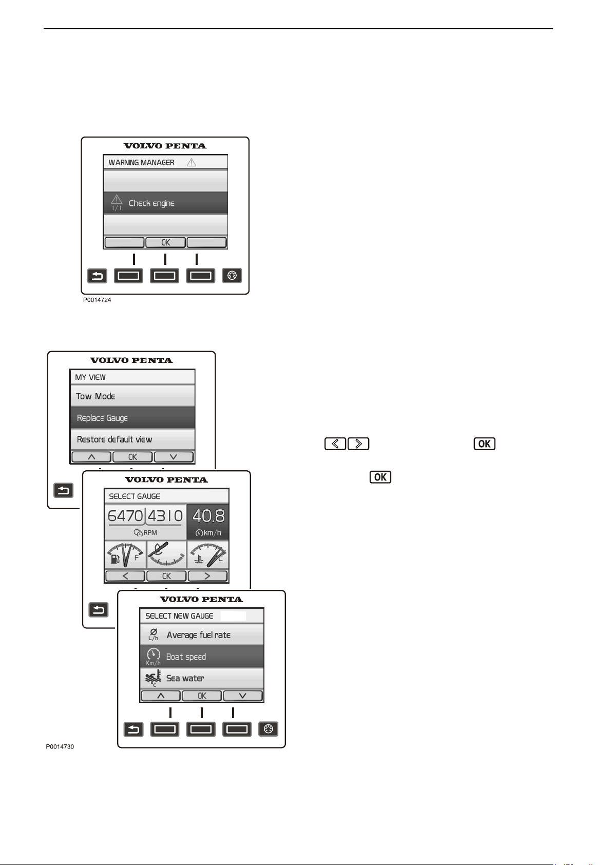
Instruments and Controls
Warning Manager
Warning Manager
If the system discovers a fault, the helmsman is
informed by a message on the display. The fault
message must be acknowledged by pressing the OK
button.
All fault messages are stored in Warning Manager,
where the affected drivetrain is shown, the fault is
described
Fault Code Register, page 71 for more information
about different fault messages.
and suitable actions are suggested. Refer to
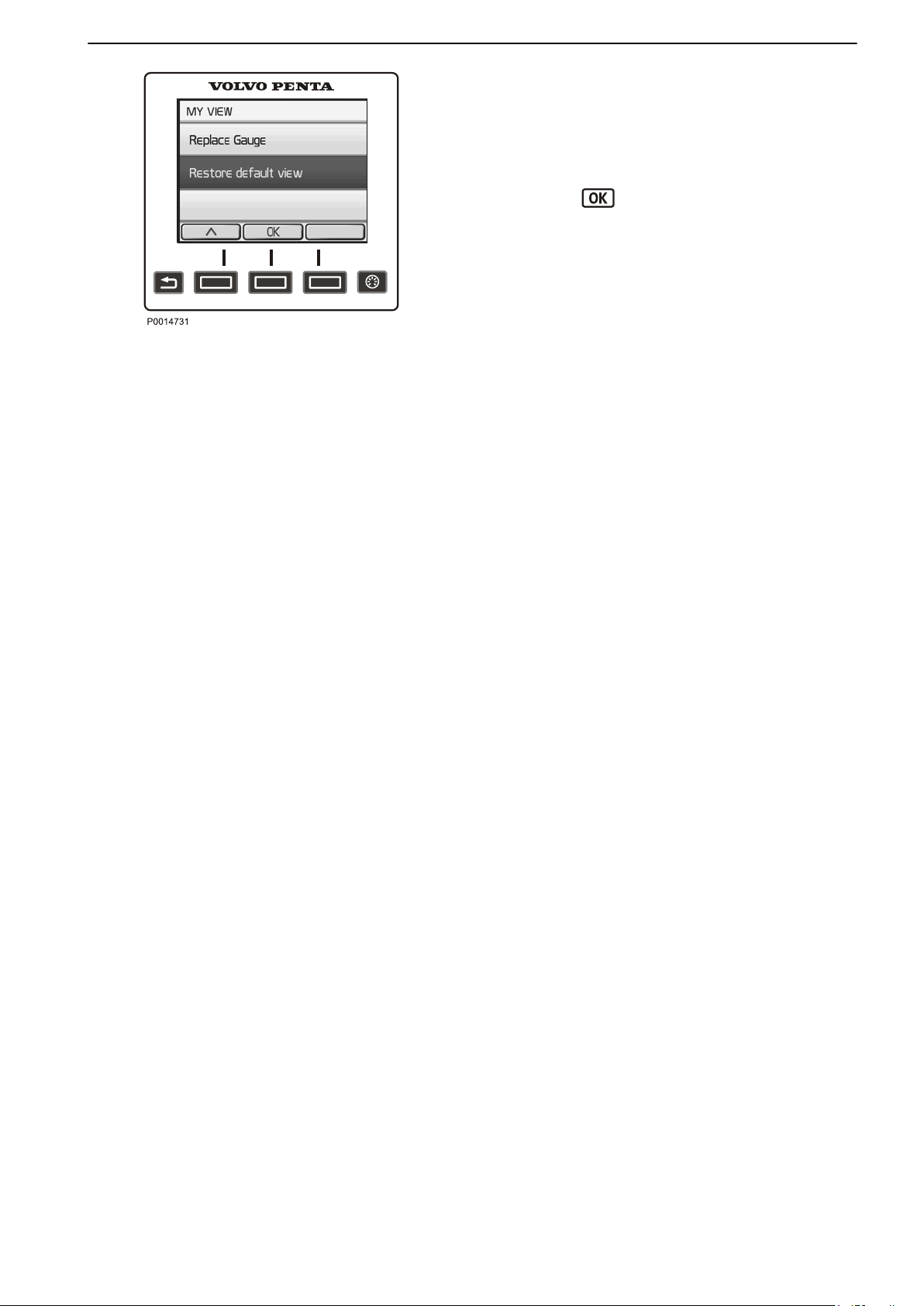
Replace Gauge
In My View, Engine View and Vessel you can decide
on what information to show and where on the display
the information is shown.
1 Press the Menu button and select Replace
Gauge.
2 Navigate to the gauge to be replaced using the
buttons and press the button.
3 Select the gauge to replace the former one and
press the button.
Replace Gauge
26 47708085 11-2016 © Bukh
Page 26
Instruments and Controls
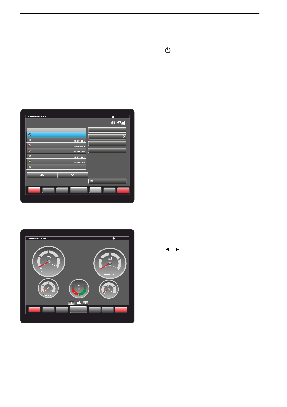
Restore Default View
To revert to the basic display settings, navigate to
Restore Default View.
Restore Default View
1 Press
View.
2
Press the
the Menu button and select Restore Default
button.
47708085 11-2016 © Bukh 27
Page 27
P0022469
GARMIN
Info
Waypoints
Engage
Home
13:26
Back
Lost Remote GPS Connection
8:42
8:42
8:42
8:42
8:34
Fault Time
Warning Manager
Sorted by Time
Autopilot lost communication with H...
Autopilot lost communication with H...
Autopilot lost communication with H...
Check Auxiliary bus
Check Auxiliary bus
Check Auxiliary bus
13-JAN-2016
13-JAN-2016
8:34
8:34
7:15
8:34
8:34
SOS
Mark
Meny
Review
Clear Warning Manager
Sort/Filter
Save to Card
P0022479
GARMIN
5
10
15
20
0
0
00
R
P
M
10
20
30
40
0
°C
MENU
Info
SOS
Mark
Waypoints
Engage
Home
40
25
75
0
100
0
0
%
%
0
300
kpa
200
100
Sea Wtr Pres
0°
13:26
Instruments and Controls
Glass Cockpit Display
The Glass Cockpit Display is switched on and off by
pressing .
NOTICE!
For information on how to navigate and customize the
Glass Cockpit display, refer to the integrated Glass
Cockpit Manual. Go to Info > Owner`s Manual to see
the manual in the display or download the latest
manual on www.garmin.com.
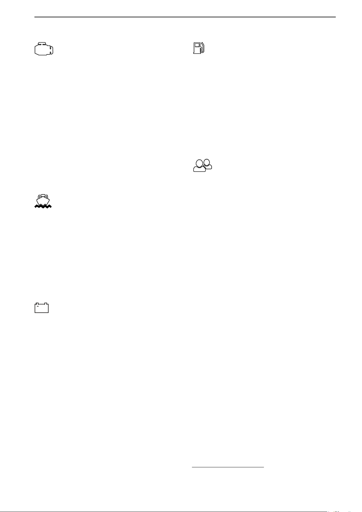
Warning Manager
Select Info > Warning Manager to navigate to
Warning Manager.
If the system discovers a fault, the helmsman is alerted
by a message on the display. Acknowledge the
message by selecting OK.
All faults are stored in Warnings Manager.
The fault message describes the fault and suggests
suitable actions.
For further information see Fault Handling, page 67
and Bukh Glass Cockpit manual.
28 47708085 11-2016 © Bukh
Gauge View
Select A/V, Gauges, Controls > Choose one of the
available gauges views .
Navigate between the different gauge views by
selecting or in the gauges menu.
Page 28
This is an example of gauges that can be displayed in the different views:
P0022484
+
Instruments and Controls
Engine View
•
Engine speed
• Engine hours
• Exhaust temperature, dry
• Coolant temperature
• Coolant pressure
• Voltage
• Oil pressure
• Turbo pressure (diesel)
• Transmission, oil pressure
• Transmission, oil temperature
•
Load percent
(1)
• Oil filter diff pressure
Vessel View
•
Active corrosion protection info
• Depth with alarm
• Fuel level
• Fresh water
• Boat speed
• Power trim angle
• Rudder angle
• Water temp
Battery View
NOTICE! The
Battery View shows battery status. The
system requires a battery sensor to be able to show
the status of the battery.
For installation without Battery Management System,
Voltage is the only gauge displayed in this view.
Fuel Economy View
• Instant fuel rate
• Average fuel rate
• Time to empty
• Instant fuel economy
• Average fuel economy
• Trip fuel economy
• Distance to empty
• Fuel level
• Fuel remaining
My View
•
Boat speed
• Fuel level
• Fuel feed pressure
• Fresh water level
• Seawater temperature
• Seawater pressure
• Rudder angle
• Interceptor position
• Lowspeed mode, slip rate
• Propulsion speed
• Trip fuel
• Total fuel rate
• Trip distance
• Trip hours
• Total fuel economy
• SOC (state of charge)
• Time to empty / Time to full
• Voltage
• Current
• Battery health
1. Shows engine torque output in percentage of available engine
torque, at current engine speed.
47708085 11-2016 © Bukh 29
Page 29

Instruments and Controls
Power Trim
Your Bukh drive is equipped with a hydraulic trim
system, Power Trim, that allows you to adjust the
angle of the drive with respect to the transom from the
helm station. The angle of the drive effects the boat's
passage through the water and other characteristics,
e.g. improved acceleration to planing and planing with
a lower throttle opening. Trimming can also be used to
give a more gentle passage in short seas.
Trim Ranges
To be able to use the information on the trim
instrument, it is important to be aware of the three trim
ranges and the way they are used.
Trim range
The trim range are used to provide the best comfort
when driving – from starting to top speed.
Beach range
The beach range is used for driving at low speed in
shallow water or where the depth is unknown.
The highest permitted engine speed when in the beach
range is 1500 rpm.
IMPORTANT:
Make sure the
of the water when operating in the beach range.
Lift range
The lift range is never used when sailing. It lifts the
drive to maximum height and is used for e.g.
transporting the boat on a trailer. Power Trim has an
automatic stop that turns off the power when the end
position is reached. The catch is released
automatically when the stern drive is trimmed down.
drive's coolant inlet is never trimmed out
WARNING!
The engine must not be run with the drive in the “lift”
range.
30 47708085 11-2016 © Bukh
Page 30
TRIM SB
TRIM PT
CRUISE
+
-
1
2
P0013214
Top mount control for twin installation
Instruments and Controls
Trim Controls
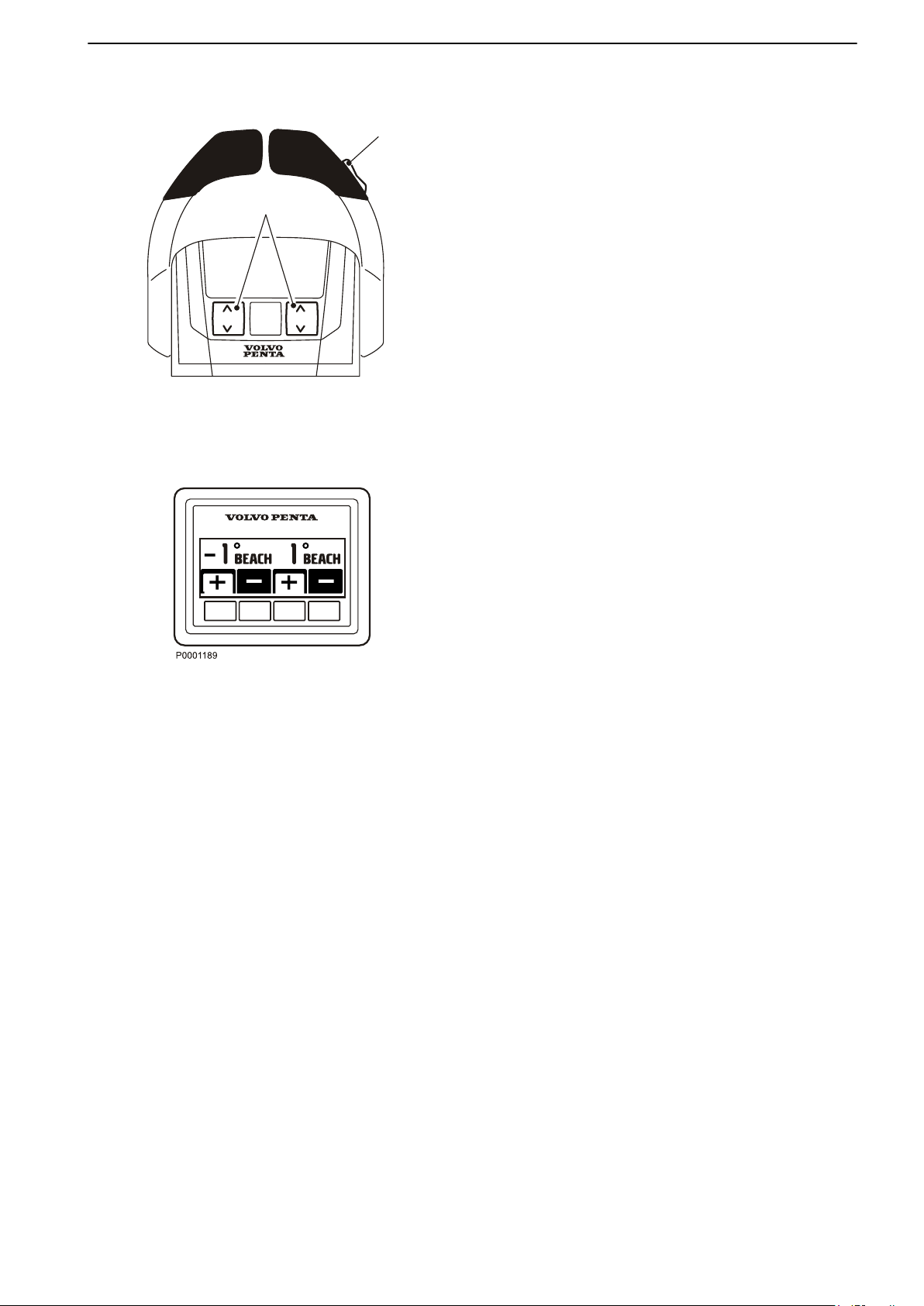
The drive can be trimmed with the Power Trim panel
or with the button at the side of the control (1).
For twin engine installations, the button at the side
adjust the drives simultaneous. There is also a button
for individual adjustments to the drives (2) on the
control for twin installations.
NOTICE! The individual drive adjustments with the
front buttons (2) is only available for installations
without Bukh Interceptor System. For information
about the Interceptor System, refer to Optional, page
52.
Power Trim panel
The Power Trim panel is used for both single and twin
engine installations. For twin engine installations, the
control panel can be used to make individual or
simultaneous adjustments to the drives.
The drive's angle and position is shown on the Power
Trim panel. By trimming out the drive away from the
transom the bow will be ”raised” in relation to the
horizontal axis and trimming in the drive will ”lower” the
bow of the boat.
Trimming out the drive
On the Power Trim panel, press button + to trim the
drive out, away from the transom. The bow will
be ”raised” in relation to the horizontal axis.
Trimming in the drive
Press button – to trim the drive in, towards the transom.
The bow will be ”lowered” in relation to the horizontal
axis.
47708085 11-2016 © Bukh 31
Page 31
STATION
THROTTLE
ONLY
CRUISE
CONTROL
SINGLE
LEVER
LOW
SPEED
TRIM
Assist
P0013276
1
2
P0002443
Instruments and Controls
Power Trim Assistant
Power Trim Assistant, PTA, adjusts the trim angel
The
automatically according to engine speed (rpm). It is
possible to set five trim angles at five different engine
speeds, idle speed included. To set the angles, please
refer to PTA Calibration, page 116.
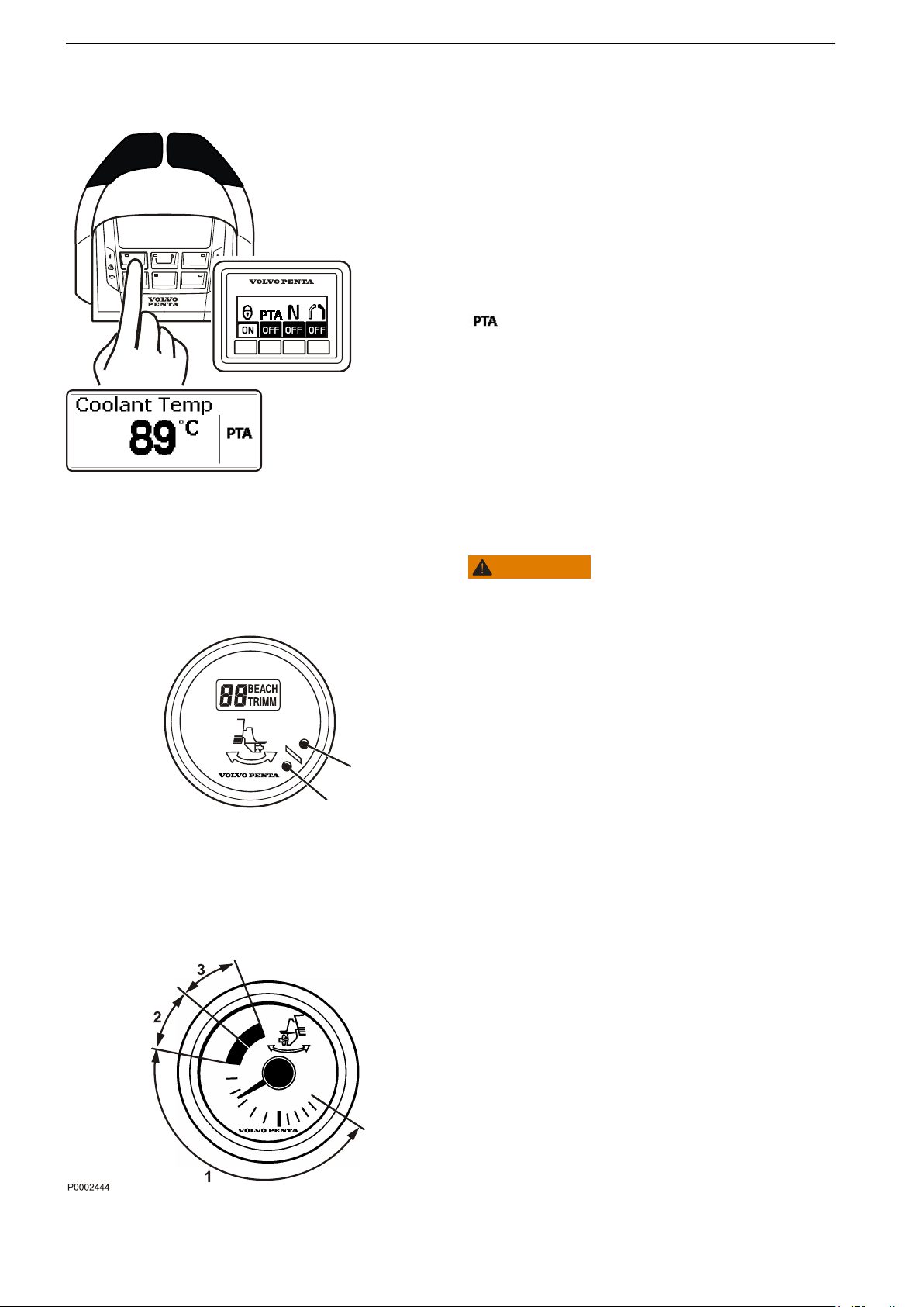
Press the PTA button on the helm station panel or the
Trim Assist button on the control to activate or deactivate the function.
is shown on the screen if the PTA function is
active.
Trim Instruments
WARNING!
The engine must not be run with the drive in the “lift”
range.
Digital trim instrument
The trim instrument shows the drive trim setting. The
of the drive is given in relation to a horizontal line.
angle
The lowest value indicates that the drive is fully
trimmed down and the highest value that the drive is
fully trimmed up. Note that the lowest value can vary
from boat to boat, depending on the angle of the
transom.
When the drive angle is within the trim range, the
text ”TRIM” is shown on the display.
When the drive angle is within the beach range, lamp
1 lights orange and the text “BEACH” is shown on the
display.
When the drive is in the lift range, the drive angle is
greater than +30° and lamp 2 lights red. There is no
text on the display.
Analog trim instrument
The trim instrument shows the drive trim setting. The
beach range is marked with an orange zone and the
lift range with a red zone.
1
Trim ranges
2 Beach range (orange)
3 Lift range (red)
32 47708085 11-2016 © Bukh
Page 32

Instruments and Controls
Maneuvering
The correct trim setting provides the best comfort when
driving.
Every boat has its own unique characteristics and
reacts differently to how you trim it. We can therefore
only give general advice about how you reach the best
trim angle for your boat. It can generally be said that
when the boat feels well balanced, is easy to steer and
comfortable to drive - than you have found the optimum
trim angle.
Make a few trips at low speed to experience the effect
of Power Trim and the different trim ranges, to see
what effect they have on the boat. Note how long it
takes for the boat to reach planing speed. Check the
tachometer, speed and the response of the boat.
Trim the drive down
The bows are pressed down and the boat accelerates
faster. It also provides better driving and steering
response at speeds below the planing threshold.
Driving with ”bow down”
The ”bow down” position is normally used during
acceleration up to planing speed, at low planing
speeds or with a short sea. With full ”bow down”, the
boat has a tendency to self-steer. You may have to
compensate with the wheel to keep the boat on the
right course. In this position, the bow of the boat tries
to go deeper in the water. If the boat is driven at high
speed or towards high waves, the bow will plough
downwards into the water. The boat can start to steer
with the bows or yaw suddenly so that passengers may
be thrown overboard.
The boat's trim shall always be adjusted to give well
balanced steering. Certain combinations of boat,
engine and propeller can cause instability and/or selfsteering tendencies when the boat is driven at or close
to the maximum ”bow up” or ”bow down” positions. The
stability and steering characteristics of the boat can
also vary depending on the sea conditions. Contact
your Bukh dealer to correct these tendencies if your
boat shows instability an/or self-steering tendencies.
47708085 11-2016 © Bukh 33
Page 33

Instruments and Controls
At planing speed
Trim the drive to the angle that gives the most stable
and comfortable feeling. If the boat has a twin
installation, the drive can be trimmed to different
angles to compensate for side winds and, to a certain
degree, uneven load distribution.
Driving with ”bow down”
The ”bow up” position is normally used for driving at
cruising speed, in short seas, or at full speed. With
”bow up” the boat can have a tendency to self-steer.
full
You may have to compensate with the rudder to keep
the boat on the right course. In this position, the bow
of the boat tries to lift out of the water. Excessive ”bow
up” trim causes propeller cavitation, so that the
propeller looses its grip. The engine speed increases
without the boat speed increasing, in fact the boat
might even sink.
Be careful when driving in short seas. Excessive ”bow
up” trim may cause the boat to bounce quickly
upwards, with the risk of throwing passengers
overboard.
In short seas or heavy head seas
Trim the drive down so that the bow drops. This makes
for a more comfortable journey.
Driving in Beach range
The beach range is used for driving at reduced speed
in shallow water or where the depth is unknown.
The highest permitted engine speed when in the Beach
range is 1500 rpm.
IMPORTANT:
sure the drive's coolant inlet is never trimmed out
Make
of the water when operating in the beach range.
34 47708085 11-2016 © Bukh
Page 34
R
F
N
T
T
P0012501
STATION
THROTTLE
ONLY
CRUISE
CONTROL
SINGLE
LEVER
LOW
SPEED
TRIM
Assist
1
2
3
4
5
6
7
8
10
9
P0013213
Instruments and Controls
Controls
This section describes the controls Bukh sells for your
engine. Contact your dealer if your boat is equipped
with controls other than those described here, and you
feel uncertain about their function.
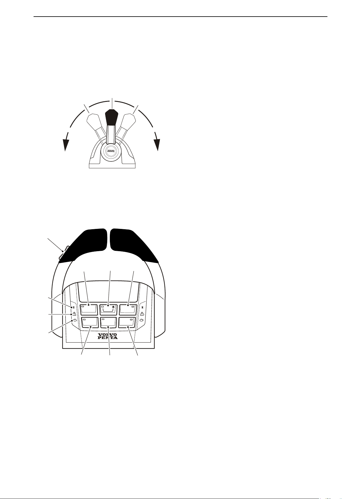
A single-lever control operates both gearshift and
throttle functions with the same lever.
The engine can only be started with the control lever
in the neutral position.
N = Neutral position. Reverse gear/drive disengaged
and engine at idle.
F = Reverse gear/drive engaged for forward motion.
R = Reverse gear/drive engaged for rearward
motion.
T = Engine rpm control (throttle).
Engine and drive features are controlled with push
buttons on the control. The buttons and functions
available depend on the installation.
1 STATION
The button lamp is lit if the helm station is active and
lit. Refer to
Operation, page 61 for further
information.
2 CRUISE CONTROL
Switch on cruise control by pressing the button.
Fine tune the locked engine speed by increasing (+)
or reducing (-) engine rpm with the button at the
other side of the control.
3 LOW SPEED (Optional)
See Optional, page 40 for information.
4 THROTTLE ONLY
Disconnects the shift function so that the control
lever only affects engine speed; refer to
"Disengaging shift function" in this chapter for
further information.
5 SINGLE LEVER
Switch on the single-lever function by pressing the
button. The lever that is moved from its position first
becomes the control lever for both engines. The
other control lever has no function as long as the
single-lever function is activated. The button lamp
lights up to show that the function is active. Exit the
single-lever function by pressing the button again.
47708085 11-2016 © Bukh 35
Page 35
Instruments and Controls
6
Neutral position. The symbol shows that the drive/
reverse gear is disengaged.
7
The warning triangle lights up if the system
discovers a fault; refer to Fault Handling, page 67
for information.
The warning triangle lights up on the same side as
the driveline with the indicated fault.
8 This function is not available.
9 TRIM ASSIST (Optional)
The Power Trim Assistant, PTA, adjusts the trim
angel automatically according to engine speed
(rpm), see Power Trim Assistant, page 32 for
information.
Depending on installation this button can switch on/
off the Interceptor System , refer to
Optional, page 52 for more information.
10 TRIM (Optional)
Trim the drive out//in.
For twin engine installations the adjustment of the
drives are synchronized. For further information
see Instruments and Controls, page 30.
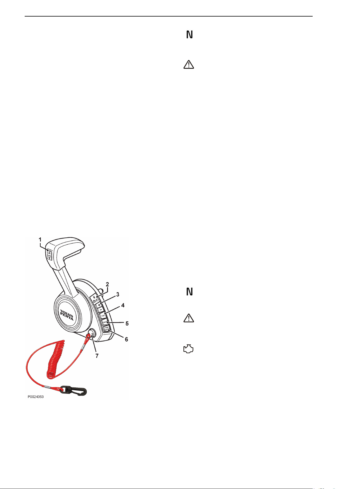
Side mounted levers
1 TRIM
Trim the drive out//in.
For twin engine installations the adjustment of the
drives are synchronized.
For further information on Power Trim see
Instruments and Controls, page 30.
2
Neutral position. The symbol shows that the drive/
reverse gear is disengaged.
The warning triangle lights up if the system
discovers a fault; refer to Fault Handling, page
for information.
67
This function is not available.
3 + / -
tune the locked engine speed for tow mode (4)
Fine
or cruise control (5) by increasing (+) or reducing (-)
engine rpm.
4 TOW MODE
Accelerates the boat to a preset rpm.
Switch on toe mode by pressing the button.
Fine tune the locked engine speed by increasing (+)
or reducing (-) engine rpm with button (3).
36 47708085 11-2016 © Bukh
Page 36

Instruments and Controls
5 CRUISE CONTROL
Switch on cruise control by pressing the button.
Fine
tune the locked engine speed by increasing (+)
or reducing (-) engine rpm with button (3).
6 TRIM ASSIST
The Power Trim Assistant, PTA, adjusts the trim
angel automatically according to engine speed
(rpm), see Power Trim Assistant, page 32 for
information.
7 Safety Lanyard
The safety lanyard is an accessory to increase the
safety if the driver of the boat falls in the boat or
overboard and the propulsion of the boat has to
stop. If the lanyard looses contact with its socket on
the lever, the engine will ramp down to idle and put
itself in neutral gear. When idle and neutral is
reached, the engine will shut down. If the safety
lanyard is pulled out, a buzzer alarm as well as
alarm on all displays will be activated. In order to
regain control, the driver or the new driver must set
lever to neutral and restart the engine. If the engine
is started without the safety lanyard attached, an
intermittent buzzer will be active. The intermittent
buzzer is active until the safety lanyard is back in
its socket.
CAUTION!
The safety lanyard should always be attached to
the current driver.
8 THROTTLE ONLY
Disconnects the shift function so that the control
lever only affects engine speed; refer to
"Disengaging shift function" in this chapter for
further information.
9 Neutral interlock
The neutral interlock prevents acidentally moving
the throttle out of neutral.
Depress
neutral.
The neutral interlock will automatically re-engage
when the control handle is returned to the neutral
position.
the interlock button to move control out of
47708085 11-2016 © Bukh 37
Page 37
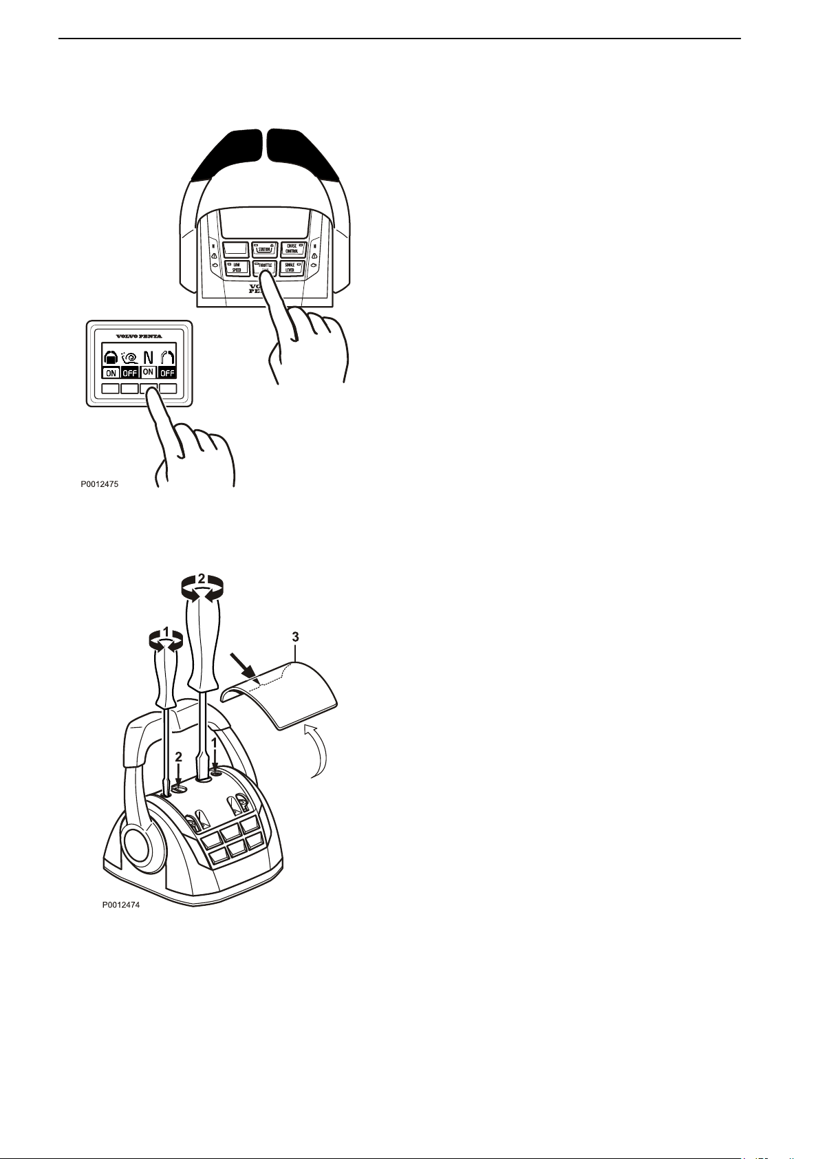
Instruments and Controls
Disengaging the Shift Function
The gearshift function can be disconnected so that the
control lever only operates the throttle.
1 Put the control levers in neutral.
2 Press the control's “Throttle Only” button or the
neutral button (N) on the helm station panel.
3 Release the button. The N symbol on the control
will light up as confirmation that the gearshift
function is disengaged and that the lever will
only affect engine revolutions.
To exit neutral mode, press the button again.
Adjusting the friction brake
Top mounted lever
The control lever has a friction brake that can be
adjusted for lighter or stiffer lever movement.
Resistance in click mode can also be adjusted.
Switch off the engine.
1
2 Remove the cover (3).
3 Adjust the friction brake (1) and/or click mode (2) by
turning the screw clockwise for stiffer lever
movement, and counterclockwise for lighter lever
movement.
4 Replace the cover.
38 47708085 11-2016 © Bukh
Page 38
2
1
3
P0013443
THRUSTER
2
3
P 0226880
Instruments and Controls
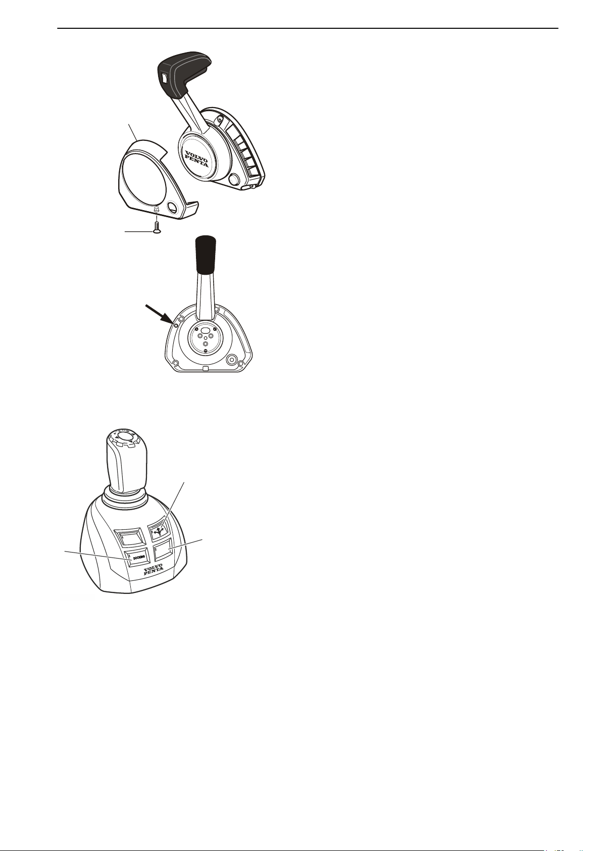
Side mounted levers
Adjust the resistance in the lever click mode.
1
Switch off the engine.
2 Unscrew the screw (1) and remove the cover (2).
3 Adjust the detention by turning the screw (3) with a
2.5 mm hex wrench. Turn the screw clockwise for
an increased detent , and counterclockwise to
decrease the detent.
4 Replace the cover.
Joystick
The joystick is optional. The features are controlled
with push buttons on the control. The buttons and
functions available depend on the installation.
1 Docking
For operation and further function information, refer
to Joystick for Docking, page 41.
2 Joystick Driving
For operation and further function information, refer
to Joystick Driving, page 46.
3 Thruster Mode / High Mode
Depending on installation the Thruster Mode or the
High Mode button is fitted at number 3.
For operation and further function information, refer
to Thruster Mode, page 44 or Joystick for
Docking, page 41.
47708085 11-2016 © Bukh 39
Page 39
Optional
P0012978
B
B
R
F
N
A
A
P0012499
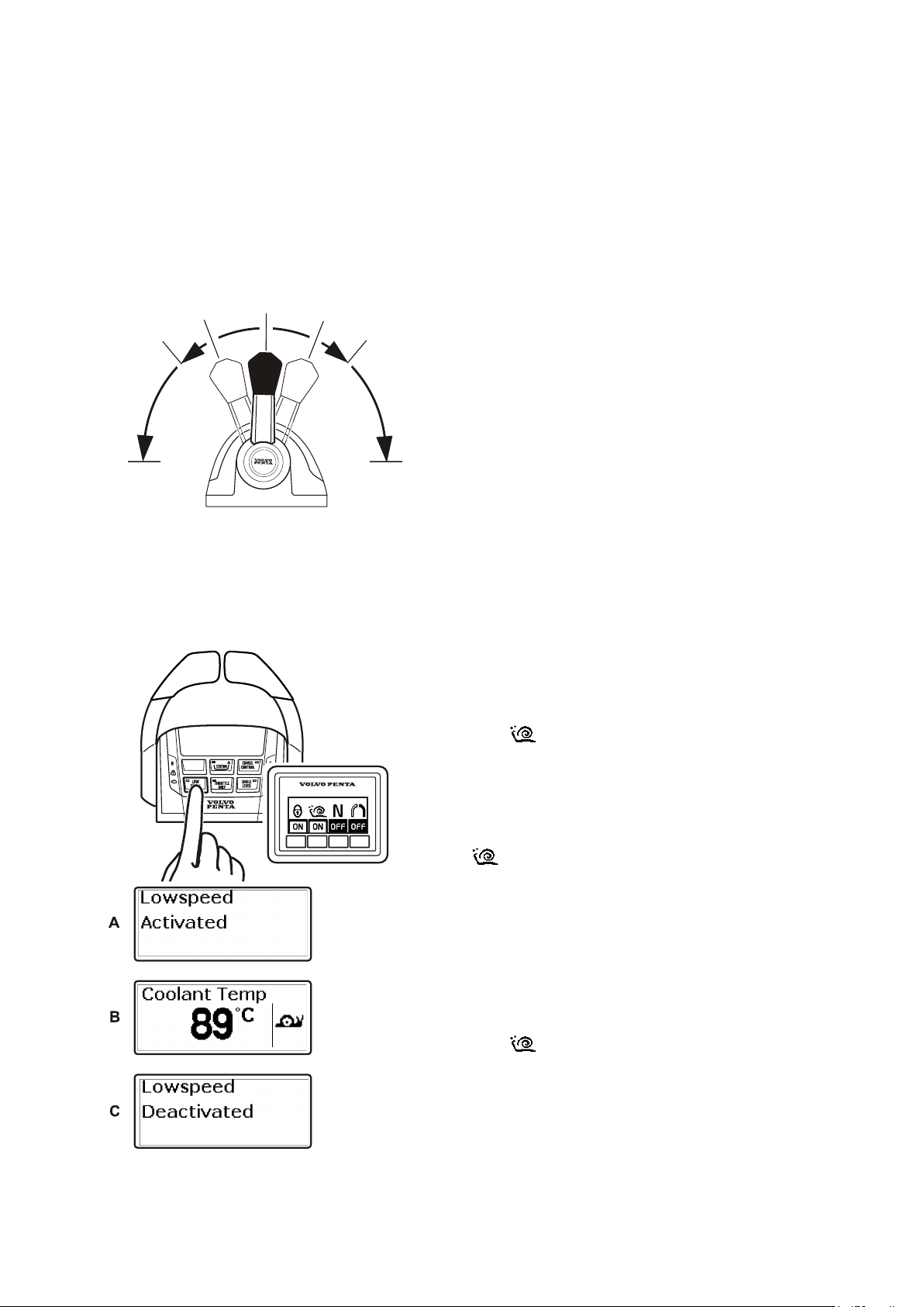
Lowspeed
The Bukh Lowspeed function is available for
engines with hydraulic transmissions.
Boats with powerful engines can have high speeds
even at low revolutions; the low speed function
reduces speed.
N = Neutral position.
Transmission is disengaged and engine
revolutions are at idle.
F = Forward at idle.
The transmission is engaged for operations
ahead and the engine is at idle; this involves
maximum trolling in the transmission.
R = Reverse at idle.
The transmission is engaged for operations
astern and the engine is at idle; this involves
maximum trolling in the transmission.
A = Low speed engaged.
The transmission affects propeller revolutions.
The engine is not affected.
B = Low speed disengaged.
The control affects engine speed and propeller
revolutions.
Engaging the lowspeed function
1 Move the lever to the neutral position.
2
Press the Lowspeed button on the control or
on the helm station panel to activate the
lowspeed function.
An audible
message (A) will be displayed on screen to
confirm that the function is on.
is shown on the screen if the low speed function
is active (B).
When the
occur when shifting.
Disengage the lowspeed function
1
2
low speed function is engaged, a delay may
Move the lever to the neutral position.
Press the Lowspeed button on the control or
low speed function.
Two audible signals confirm that the function is
switched off and the “Lowspeed deactivated”
(C) message is displayed on the screen.
signal and the “Lowspeed activated”
on the helm station panel to disengage the
40 47708085 11-2016 © Bukh
Page 40
Optional
Joystick
Bukh Joystick is a control used for docking and
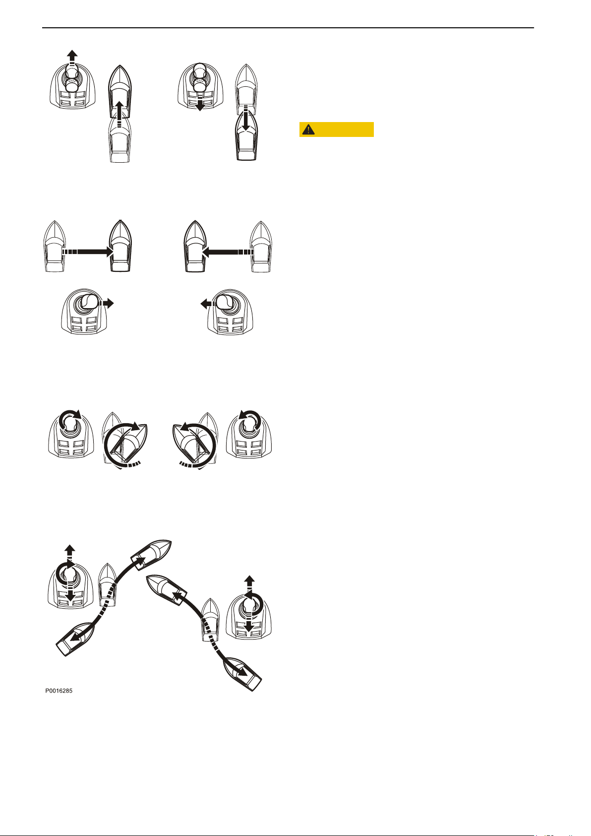
maneuvering. Practise using the joystick and its
functions in a safe and proper manner.
Practise how to operate the boat with both joystick
docking and steering functions.
CAUTION!
The joystick
on if the docking function or steering function is active.
Practise using all means of steering and throttle under
all conditions.
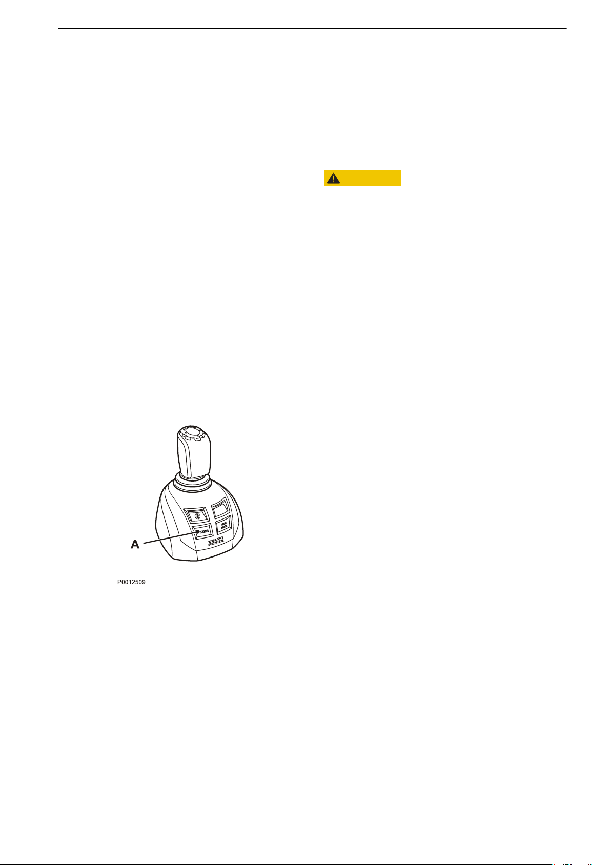
Joystick for Docking
When the docking function is activated, engine
revolutions are limited and the boat can only be
steered by the joystick.
In order to activate the docking function, the following
must be fulfilled:
maneuvering works differently depending
engines running
•
control levers in neutral
•
helm station active
•
joystick in center position
•
Activating the docking function
Activate docking mode by depressing the docking
button (A) on the joystick.
An audible signal will confirm that docking mode is
activated and the docking button lamp will light up.
Exiting the docking function
To exit the function, press the joystick docking button
(A). An audible signal will sound twice to confirm that
docking mode is deactivated, and the docking light will
go out.
The docking function is also deactivated if the controls
are moved from the neutral position.
47708085 11-2016 © Bukh 41
Page 41
Optional
Bukh Joystick is a control used for docking and
maneuvering. Practise using the joystick and its
functions in a safe and proper manner. Practise how
to operate the boat with both joystick docking and
steering functions.
CAUTION!
The joystick maneuvering works differently
depending on if the docking function or steering
function is active.
Practise using
all conditions.
The docking function is designed to be used when
docking or maneuvering in close quarters. Use the
steering wheel and throttle control levers in all other
situations.
The boat is maneuvered by moving the joystick
forward, aft,
combinations of the movements.
all means of steering and throttle under
abeam, twisting the top of the joystick and
42 47708085 11-2016 © Bukh
Page 42
Optional
CAUTION!
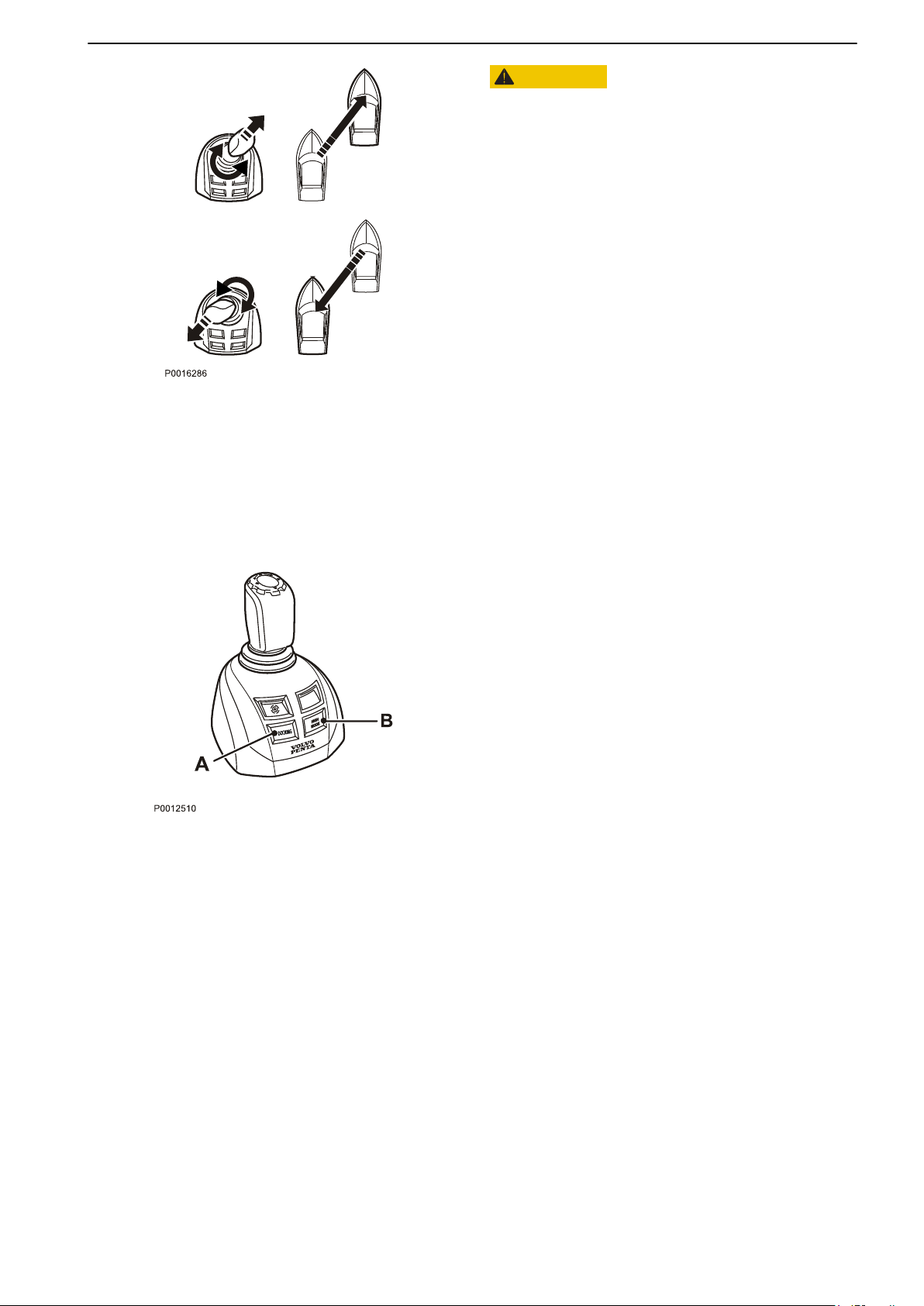
The
boat will continue to move in the selected direction
even when the joystick has been released.
To slow the boat or reverse its direction, move the
joystick in the opposite direction. In order to achieve a
diagonal movement, move the joystick diagonally and
use the joystick knob to adjust the boat’s direction
accordingly.
High Mode
If extra power, e.g. when there is a strong wind or
strong current, the High Mode function may be
engaged.
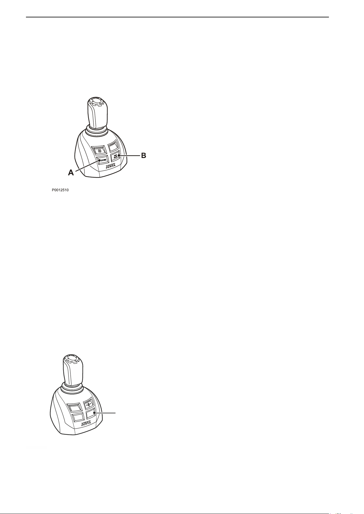
Activate High Mode
1 Activate the joystick by depressing the docking
button (A). An audible signal confirms that the
joystick is activated and the docking button lights
up.
2 Activate the High Mode function by depressing
button (B) on the joystick.
3 An audible signal confirms that the function is
activated and the high Mode button lights up.
Disengage High Model
Disengage the function by pressing the button again.
An audible signal will sound twice to confirm that
docking mode is deactivated, and the light will go out.
The system is now in normal docking mode.
47708085 11-2016 © Bukh 43
Page 43
P0022629
THRUSTER
DOCKING
P0022629
1
Optional
High Mode
If extra power, e.g. when there is a strong wind or
strong current, the High Mode function may be
engaged.
Activate High Mode
Activate the joystick by depressing the docking
1
button (A). An audible signal confirms that the
joystick is activated and the docking button lights
up.
2 Activate the High Mode function by depressing
button (B) on the joystick.
3 An audible signal confirms that the function is
activated and the high Mode button lights up.
Disengage High Model
Disengage the function by pressing the button again.
An audible signal will sound twice to confirm that
docking mode is deactivated, and the light will go out.
The system is now in normal docking mode.
Thruster Mode
When Thruster Mode is activated, the joystick only
controls the thruster(s) and the boat’s movement is
limited to rotational or rotational and sideways
depending on installation.
The boat can still be maneuvered with the steering
wheel and levers when Thruster Mode is activated.
Activate Thruster Mode
Thruster Control is activated by pressing the
THRUSTER button (1) on the joystick. An audible
signal confirms that the function is activated and the
thruster control button lights up.
Deactivate Thruster Mode
Deactivate the function by pressing the THRUSTER
button (1). The light will go out and an audible signal
will confirm that thruster control is deactivated.
NOTICE! The function is automatically deactivated if
the boats speed exceed 10 knots.
44 47708085 11-2016 © Bukh
Page 44
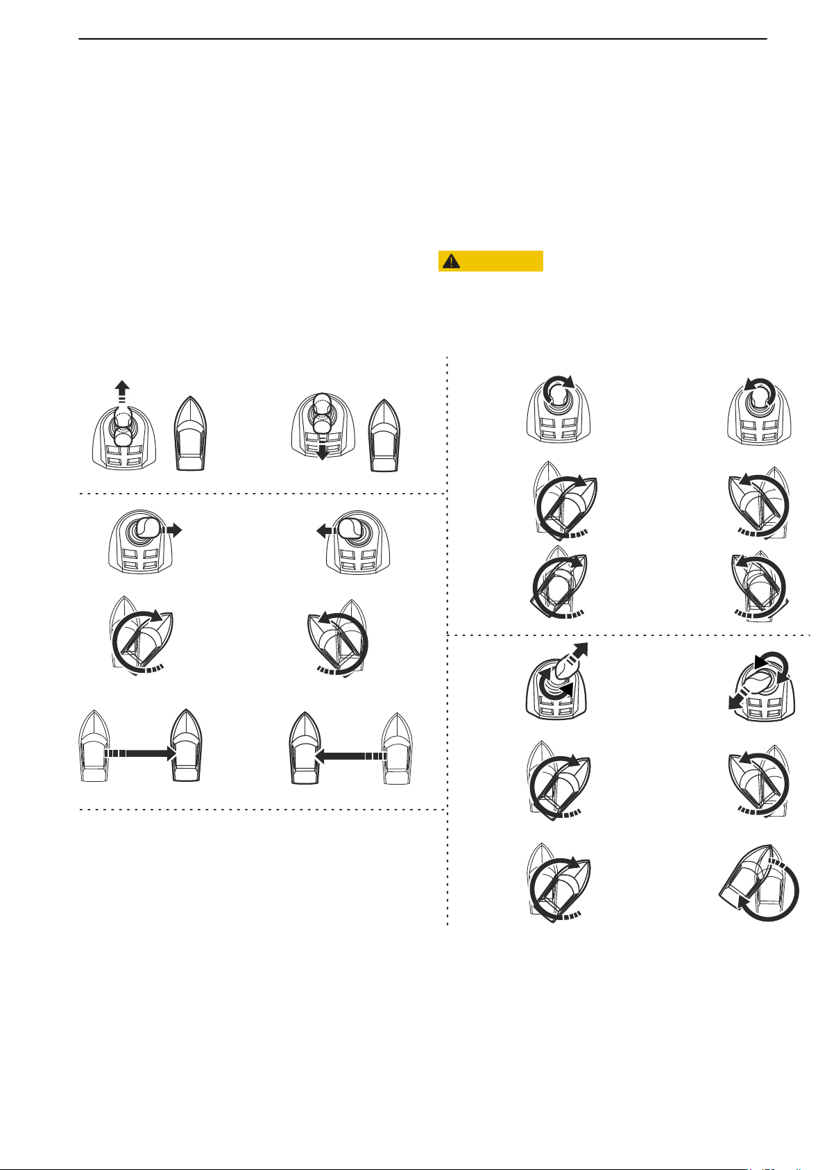
Installation 1
Installation 2
No movement.
No movement.
Installation 1 / Installation 2
Installation 2
Installation 1
P 2262800
Installation 2
Installation 1
Optional
The boat can be equipped with just a bow thruster
(Installation
1) or with both a bow and a stern thruster
(Installation 2).
The boat is maneuvered by moving the joystick
forward, aft, abeam, twisting the top of the joystick and
combinations of the movements.
Depending on installation, the boat’s movement may
differ. The pictures shows the boat’s movement for
each installation.
CAUTION!
The
boat will continue to move in the selected direction
even when the joystick has been released. To slow the
boat or reverse its direction, move the joystick in the
opposite direction.
47708085 11-2016 © Bukh 45
Page 45
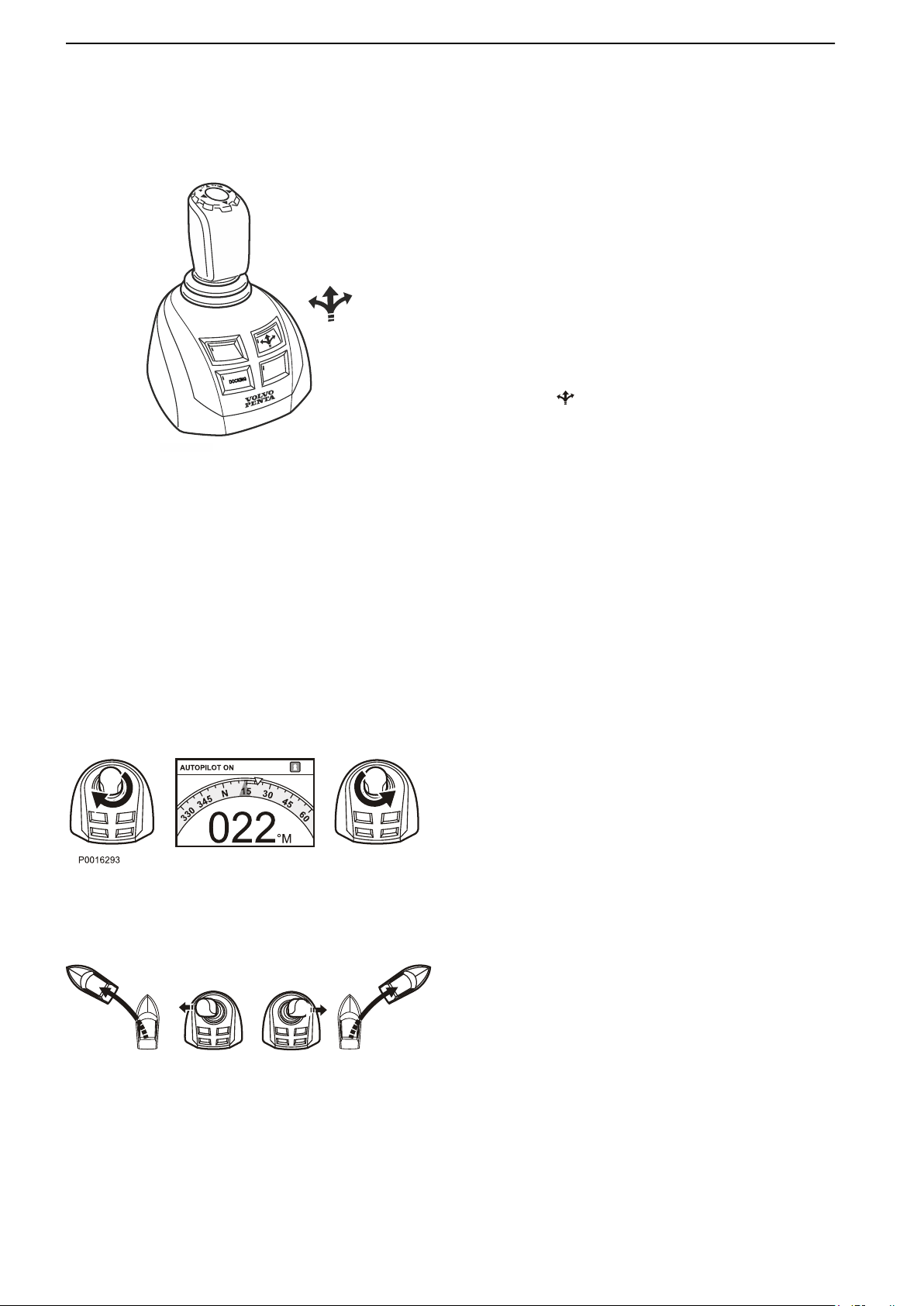
THRUSTER
P 2268600
P0004011
Optional
Joystick Driving
NOTICE! Function Joystick Driving only works
together with Bukh autopilot.
The Joystick Driving function allows the joystick to be
used during passage to adjust the boat's heading and
maneuver the boat in the same way as with the
autoplilot and helm steering unit.
Throttle and gear shift controls work in the normal
manner.
Learn to maneuver the boat with the joystick in calm,
open waters.
Joystick Driving is activated and de-activated by
pressing the button on the joystick.
When Joystick Driving is activated, the autopilot is also
started. While the boat is under joystick control the
autopilot is in standby mode; when the joystick is
released to its central position, the autopilot is
activated and locks in on the new heading after a few
seconds.
Like the autopilot, the helm steering unit is locked when
the function is active but it may always be used for e.g.
changing course or giving way to an obstacle. Twist
the top of the joystick or move it sideways to reengage
Joystick Driving.
If the autopilot is put in standby mode manually by
means of the STBY button, Joystick Driving is switched
off and must be reengaged using the button on the
joystick.
Heading adjustments
Twist the top of the joystick to change heading
incrementally. A short twist changes the heading by a
fixed increment while a twist held firm will change the
heading through several increments.
The autopilot shows the heading with a digital value
and a indicator in shape of a blue triangle, a yellow
arrow shows the new heading that the boat will be set
to.
Maneuvering
The joystick can also be used to maneuver the boat in
the same manner as with a helm steering unit. Move
the joystick sideways to steer the boat in the same
direction. When the joystick is released, the autopilot
will set a new heading that corresponds to boat
heading.
NOTICE! Full joystick movement to one side
corresponds to full helm. Maneuvering abeam
provides a faster response than adjusting the heading
by twisting the top of the joystick.
46 47708085 11-2016 © Bukh
Page 46

Optional
Autopilot
For information about Autopilot in glass cockpit
displays, refer to the Glass Cockpit Manual. Go to Info
> Owner’s Manual to see the manual in the display or
download the latest manual on www.garmin.com
Bukh Autopilot consists of a compass unit and the
Glass Cockpit Display. The autopilot adjusts boat
steering to hold the boat on a straight course. Several
different steering patterns can be set and the autopilot
also permits manual steering.
Read the instructions carefully and learn to maneuver
the boat with the aid of the autopilot in calm, open
waters.
NOTICE! The helmsman is responsible for piloting the
boat in a safe, reliable manner, even when the
autopilot is enabled. Avoid navigational hazards and
never leave the helm unattended. Always be prepared
to quickly take over the helm.
The autopilot is automatically in standby mode when
the boat's electrical systems are switched on. The
display will show the main menu or the last menu used.
When the autopilot is active, the helm steering unit is
locked but may be used for e.g. changing course or
giving way to obstacles. If the helm steering unit is
used, the autopilot will automatically enter standby
mode and must be reactivated again to function.
47708085 11-2016 © Bukh 47
Page 47
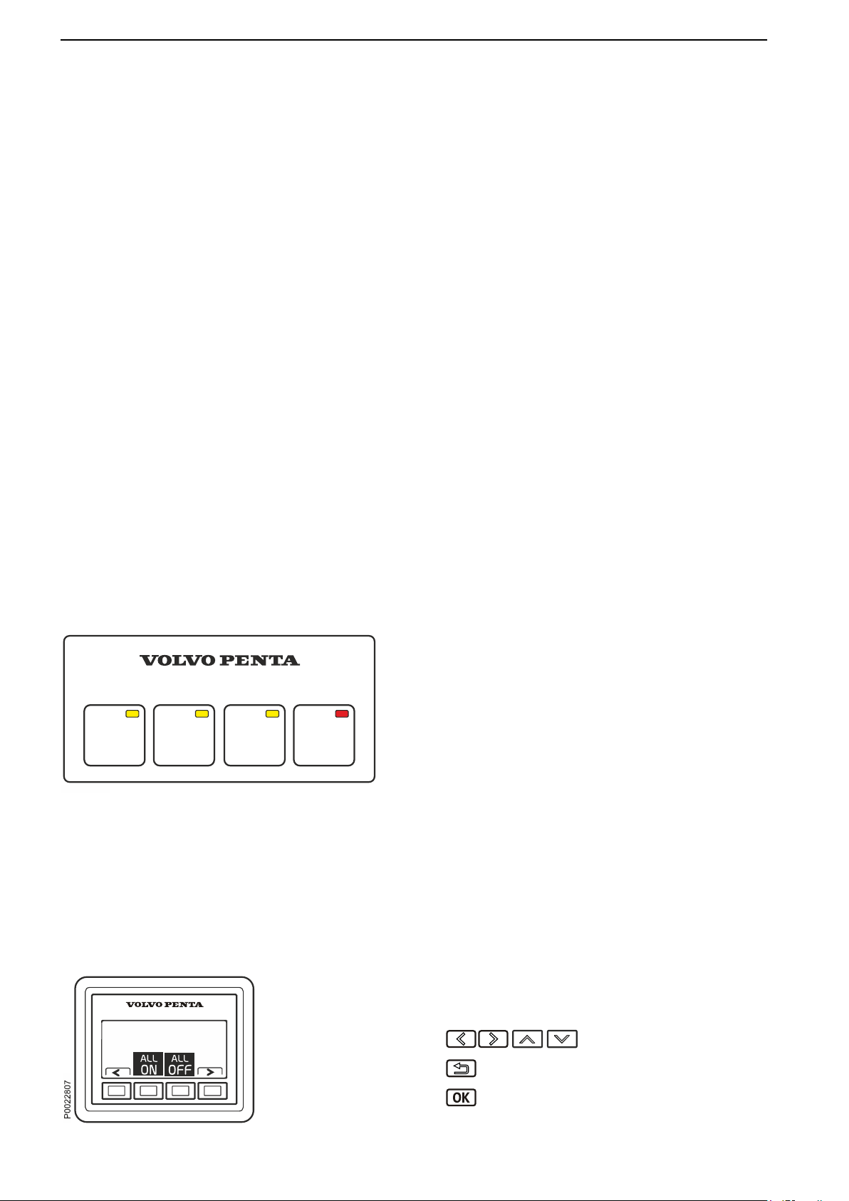
BATTERY2BATTERY1CROSS
OVER
REMOTE
DISABLE
P0021304
Optional
Battery Management System
The Battery Management system helps to ensure
availability and robustness in power supply to the
starter and other power consumers on board.
Depending on installation, the local controls on the
Battery Management unit(s) or both the local controls
and the Battery Management Display can be used to
control the system.
Local Control
The keypad on the BCM has four buttons, 3 for
switches
The switches not only switch power supply on and off
but are also able when necessary to cross connect the
service battery to the starter motor circuit when the
start battery does not provide sufficient power to the
starter motor.
and one to disable remote control of the BCM.
Remote disable.
- BATTERY 1: Turns off/on the power supply for start
motor and any power-user.
- BATTERY 2: Turns off/on the power supply for
selected accessories.
- CROSSOVER: Crossover function. Activates cross
over function between the batteries connected to
the BCM. To secure power-supply.
Remote disable
In order to prevent inadvertent activation of the
breakers (via the Battery Management display or
external wired switches) when working on the boat’s
electrical system, remote control of the breakers can
be deactivated.
Press REMOTE DISABLE (red LED on the button
lights up) for deactivation of remote control. The
breakers can still be controlled locally on the BCM.
Deactivation/activation is synchronized between all
BCMs in the network.
Battery Management display
48 47708085 11-2016 © Bukh
The menus are dynamic depending on the installation.
Information about the battery's voltage as well as
menus for battery control and settings are shown as
standard.
Warning messages and other pop-up messages are
also shown here. At start or during standby mode the
display reverts to the view last shown.
Scroll through the menus.
Return to the previous menu.
Proceed through the menus/confirm
selection(s).
Page 48
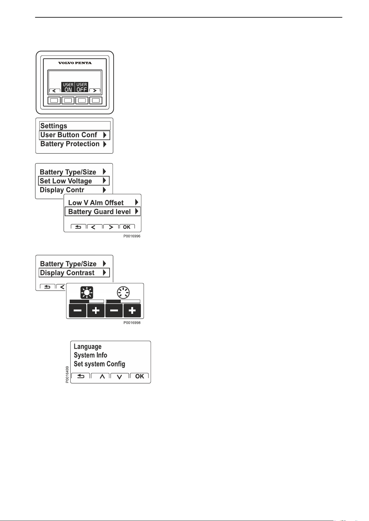
Optional
Settings
Manage and set viewing of drivelines, groups,
batteries and alarm levels in the Battery Management
display.
User Button Configuration. Battery and Accessory
Groups.
ON and User OFF. The selected groups will then be
handled simultaneously by: All ON respective All OFF.
Battery protection. Set alarm limits and levels for
each battery. The values form the basis for when
specified levels will alert/switch off to prevent total
power loss or battery getting damaged or drained. The
menu includes settings for Start Aid and Start Aid
Level .
Set selection of groups to be affected by User
Display Contrast. Adjustment of contrast and
backlighting.
Stand-alone system, non EVC installations also
have the menus Language, System Information and
Set System Configuration.
47708085 11-2016 © Bukh 49
Page 49
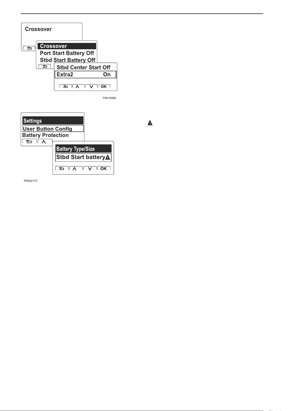
Optional
Crossover Activate/deactivate the function for each
individual BCM.
Settings for Battery Sensor
The symbol indicates that settings are required.
Battery type/size. State the values stated on the
manufacturer’s battery. These form the basis for the
information shown in the display.
If a new battery or a battery sensor has been
connected or removed, select Reset
current values.
and set the
NOTICE! Battery type/size is important so that the
system is able to present accurate and correct
information.
50 47708085 11-2016 © Bukh
Page 50
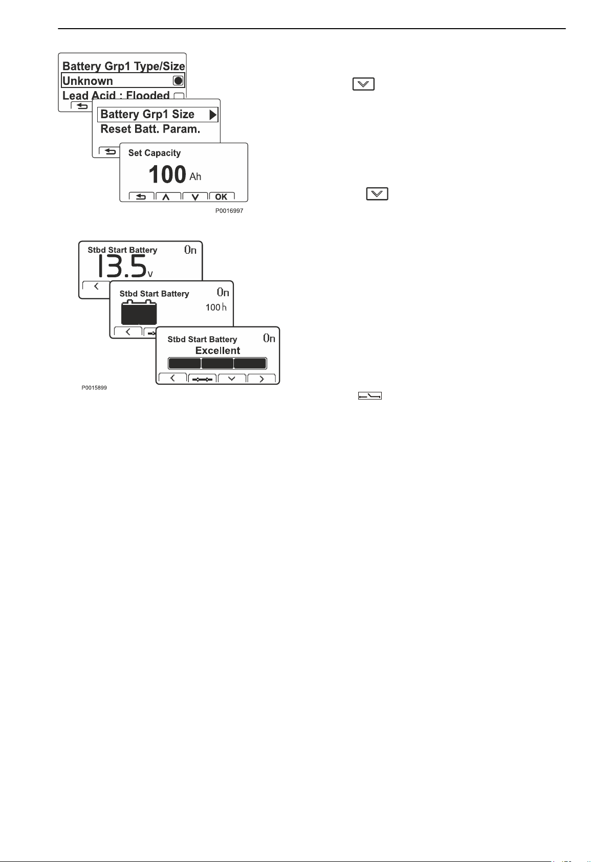
Optional
View Voltage/current
Relevant voltage and current in the battery.
Press to view:
Charging
Shows
capacity when it was new) and hours remaining until
battery is empty. During operations, the number of
hours are shown until the battery is empty, and when
the battery is charged, the number of hours are shown
until a fully-charged battery.
Pressing
The battery's health status
The value shown is based on full capacity when the
battery was new. The battery can have the following
status:
- Excellent – no action required.
remaining capacity (%) (based on the battery's
again shows:
- Good –
its full capacity.
- Poor – replace the battery.
The batteries' status (On/Off) for the driveline is shown
with a symbol at the bottom of the Battery Management
display
good status but the battery will not achieve
= Off.
47708085 11-2016 © Bukh 51
Page 51
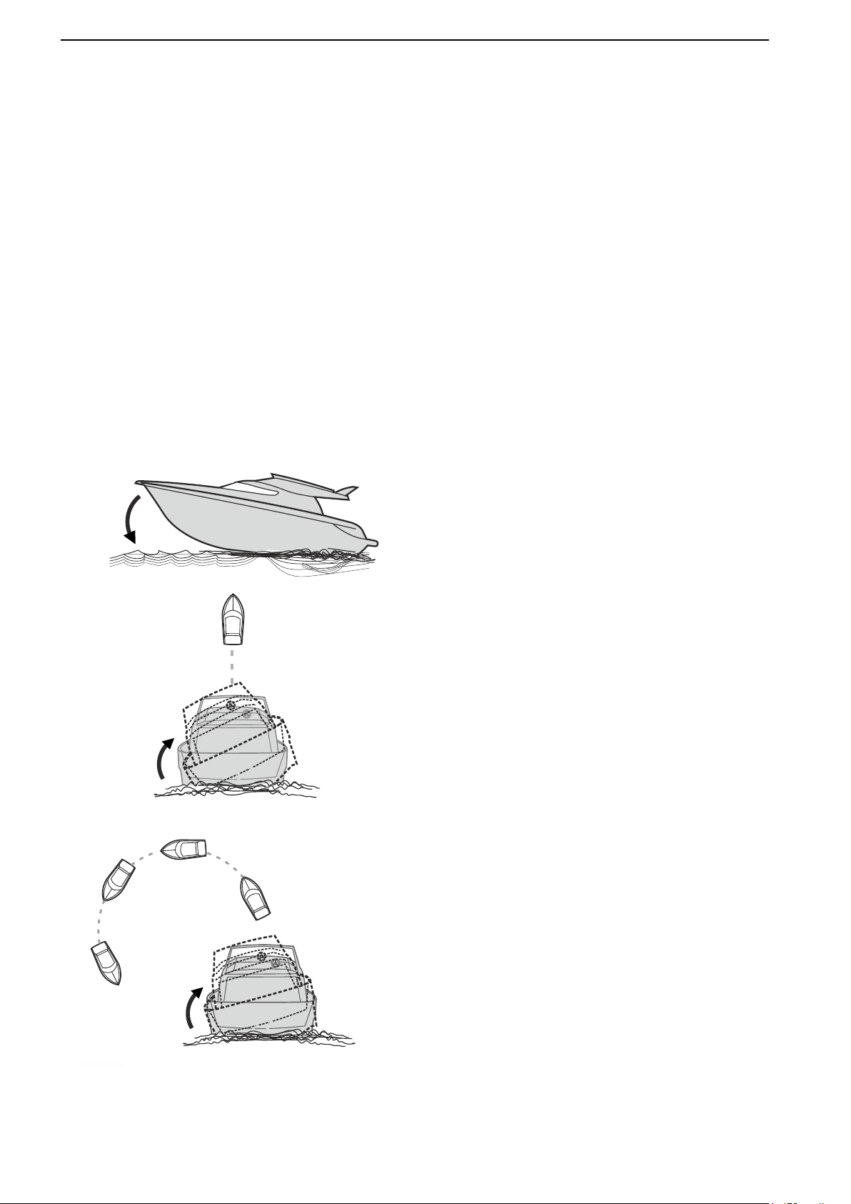
A
B
C
P 1974600
Optional
Bukh Interceptor System
The Bukh interceptor system is a trim system that
uses interceptors installed on the transom to act on a
boat's running characteristics and provide a safer,
more comfortable passage regardless of weather
conditions.
The IS system affects a boat's running characteristics
at speeds of ≈10 knots and above.
Each interceptor has a blade that extends by varying
amounts, depending on the preferred effect, and trims
the boat in three axes. The IS system is available in
two versions, manual and auto.
Manual means the helmsman controls the interceptor
blades using control buttons.
Auto means the system is pre-calibrated and
interceptor blade control is completely automatic to
provide optimum safety and comfort.
For further information refer to Operation, page 53:
A Trimming angle of attack (the angle between the
bow and the surface of the water). Improves the
helmsman's visibility to provide safer passage.
B Trimming roll angle when moving dead ahead.
Compensates boat
when the boat is unevenly laden or in a side
wind.
C Trimming roll
heel, improves the helmsman's all-round
visibility and provides for a more pleasant
passage.
heel to improve comfort e.g.
angle in turns. Compensates boat
52 47708085 11-2016 © Bukh
Page 52
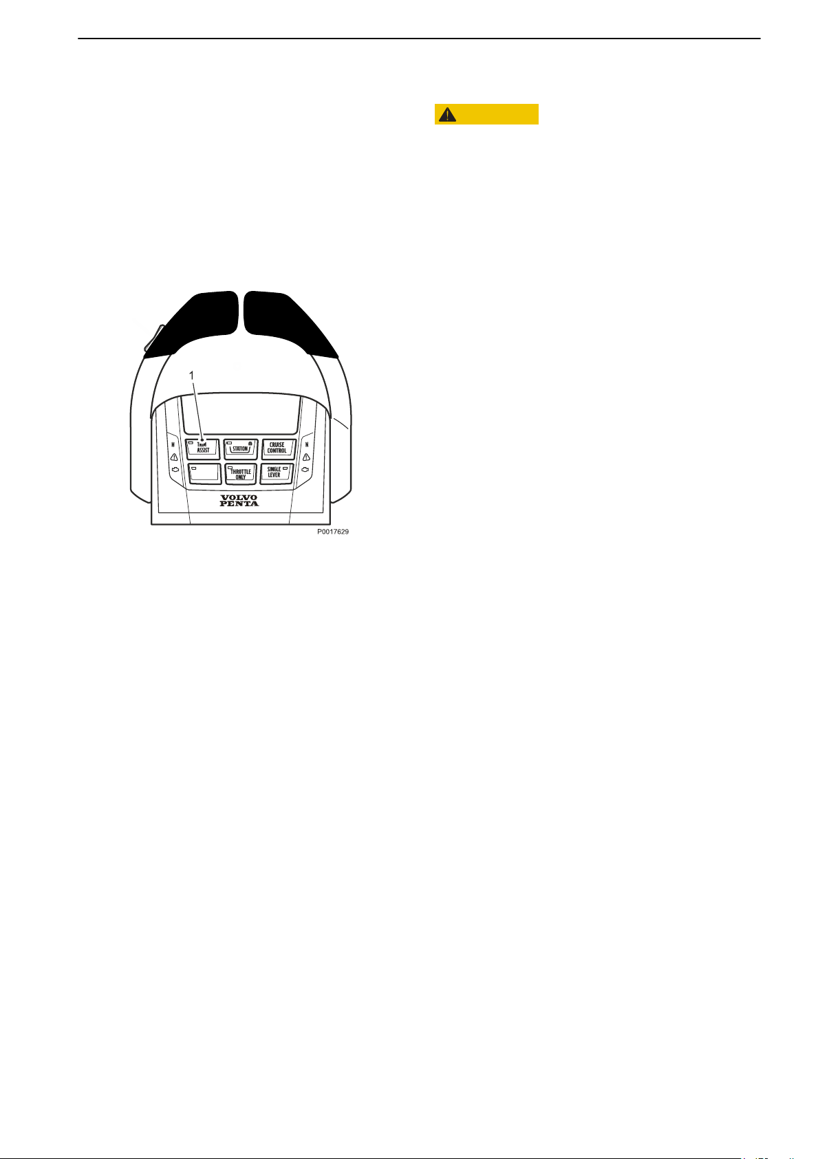
Optional
Operation
CAUTION!
Learn to manage the system and how it affects your
boat in a safe and proper manner at calm conditions.
Aquamatic
In
the case of aquamatic installations the PTA (Power
Trim Assist) function is always switched on. Individual
adjustment of the sterndrives is not possible.
Auto
Press the TRIM ASSIST button (1) to switch on the
Auto function; The button's green lamp indicates that
the function is on. The system now controls the
interceptors automatically.
It is possible to switch between automatic and manual
interceptor blade control in the Auto version. To take
manual control, switch off the auto function by pressing
the TRIM ASSIST button; when the button lamp is
extinguished the function is off. The interceptor blades
are now controlled entirely by the control buttons.
NOTICE! At start up, the system assumes the mode
last selected, auto or manual.
The control buttons may be used to temporarily adjust
boat trim even when the auto function is switched on.
The auto function is still active but the system changes
default mode. To revert to pre-calibrated auto mode,
press the TRIM ASSIST button twice.
47708085 11-2016 © Bukh 53
Page 53
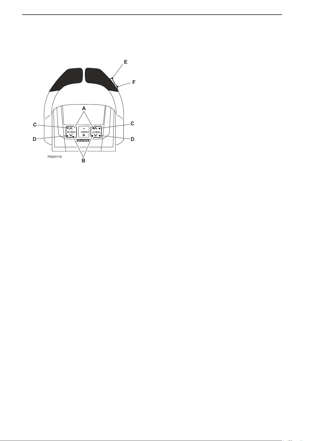
Optional
Manual control using control buttons
Manual control of the interceptors is performed using
the buttons at the back of the control.
A
All interceptors are trimmed upward
simultaneously. The bow is raised.
B All interceptors are trimmed downward
simultaneously. The bow is lowered.
C Port and starboard interceptors are trimmed
upward individually. Used to correct heel.
D Port and starboard interceptors are trimmed
downward individually. Used to correct heel.
E All drives are trimmed upward simultaneously.
F All drives are trimmed downward simultaneously.
If both the port and starboard buttons at the back of the
control are pressed at once all interceptors are
trimmed in the same way as when using the control
lever button.
In installations with four interceptors, the interceptors
are trimmed in port and starboard pairs.
Screen Display
Interceptor blade position, i.e. how far the blades are
extended, can be presented in one of the EVC system
displays. The display will also indicate if the system is
in auto or manual mode.
In installations with four interceptors, the interceptors
are presented in port and starboard pairs.
Cleaning
The system automatically performs self cleaning by
extending and retracting the blades once every 24
hours to prevent fouling of the interceptor blades. Self
cleaning is performed whether or not the boat is in use.
During prolonged inactivity, e.g. winter lay-ups, self
cleaning can be switched off by turning off the circuit
breaker or disconnecting power.
54 47708085 11-2016 © Bukh
Page 54

Optional
Swim platform Interface
A
swim platform interface can be connected to the EVC
system in a boat with a movable swim platform. The
interface will detect the position (up/down) of the swim
platform and prevent the engine/s from cranking or
drive/s to be trimmed up if the swim platform is
lowered. It is possible to override the inhibit of crank
and trim following the instructions for override in the
display. Be aware of that perform override could
damage the swim platform or drives. The interface will
also disable the possibility to lower the swim platform
when any engine is running, drive position is not
centered or drive/s trimmed too high. To be able to
control the swim platform when a swim platform
interface is connected, all drivelines need to be in
ignition ON.
47708085 11-2016 © Bukh 55
Page 55
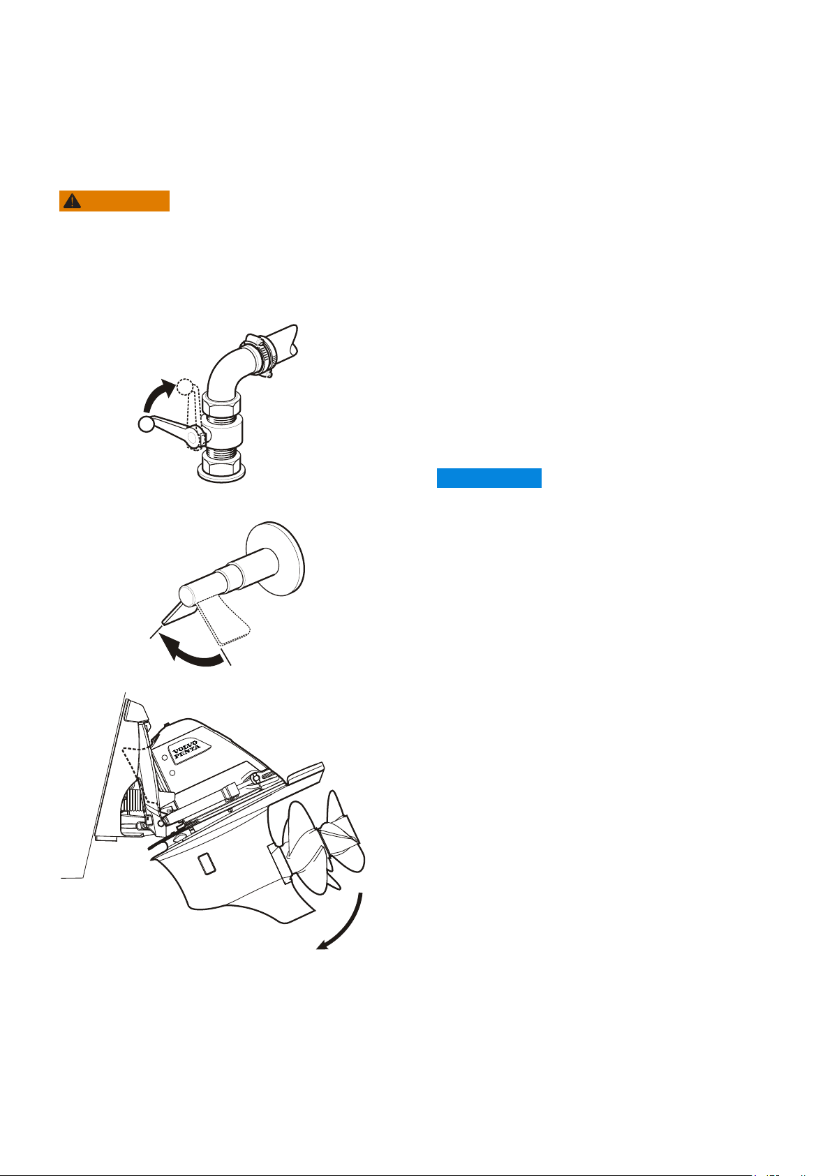
Starting
1
0
P0005850
Make a habit of visually checking the engine, engine bay and transmission before start. This will help you to
discover
displays show normal values when you have started the engine.
To minimize cold start smoke we recommend you install an engine heater or engine bay heater if temperatures
below +5°C (41°F) are encountered.
Never
of personal injury.
quickly if anything abnormal has occurred, or is about to occur. Also check that instruments and warning
WARNING!
use start spray or similar agents to start an engine. This may cause an explosion in the inlet manifold. Risk
Before Starting
Check the engine and transmission oil level.
•
Check the coolant level.
•
Open the sea cock where fitted.
•
Open the fuel cock.
•
Turn the main switch(es) on.
•
IMPORTANT:
Never disconnect the current using the main
switches when the engine is running.
The alternator and electronics could be damaged.
If the boat is fitted with an e-Key; unlock the EVC
•
system with the e-Key.
Start
•
•
•
the engine bay fan, where fitted, and allow it to
run for at least four minutes.
Check that there is sufficient fuel for the planned trip.
Lower the stern drive if it is up.
56 47708085 11-2016 © Bukh
Page 56
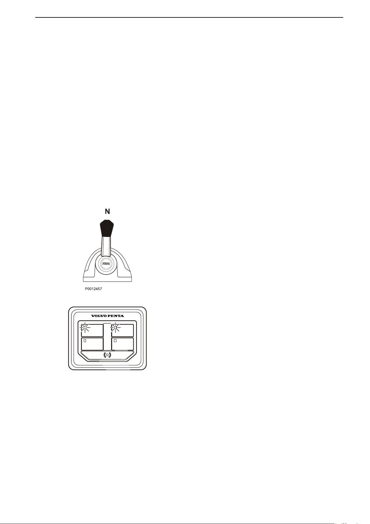
IGNITION IGNITION
START/STOP START/STOP
P0016670
Starting
Starting the Engine
Shifting and adjusting speed is only possible at an
active station.
On
a boat with one station the station is always active.
On a boat with two or more stations the main station
automatically becomes active when the engine is
started up with the ignition key(s). If the engine(s) is/
are started from another station this station
automatically becomes active instead.
Shifting and adjusting speed is only possible at an
active station. On a boat with one station, the station
is always active.
The main station is automatically activated when the
EVC-system is unlocked with the e- Key panel.
On a boat with two or more stations, the engine(s) can
be started from another station with a start/stop panel
– if the engine(s) are turned off. The station
automatically becomes active when the engine(s)
is/are started.
Put the Gear in Neutral
Put the drive/reverse gear in Neutral by moving the
control lever(s) to Neutral (N) at all stations.
Turn On the Ignition
A green light in the IGNITION
button indicates that the
ignition is on.
Press the IGNITION button to switch on the ignition if
the green light is not shining.
Check the instruments
If a fault is registered, it will be shown in the display;
please refer to Fault Handling, page
67 for further
information and recommended actions.
47708085 11-2016 © Bukh 57
Page 57
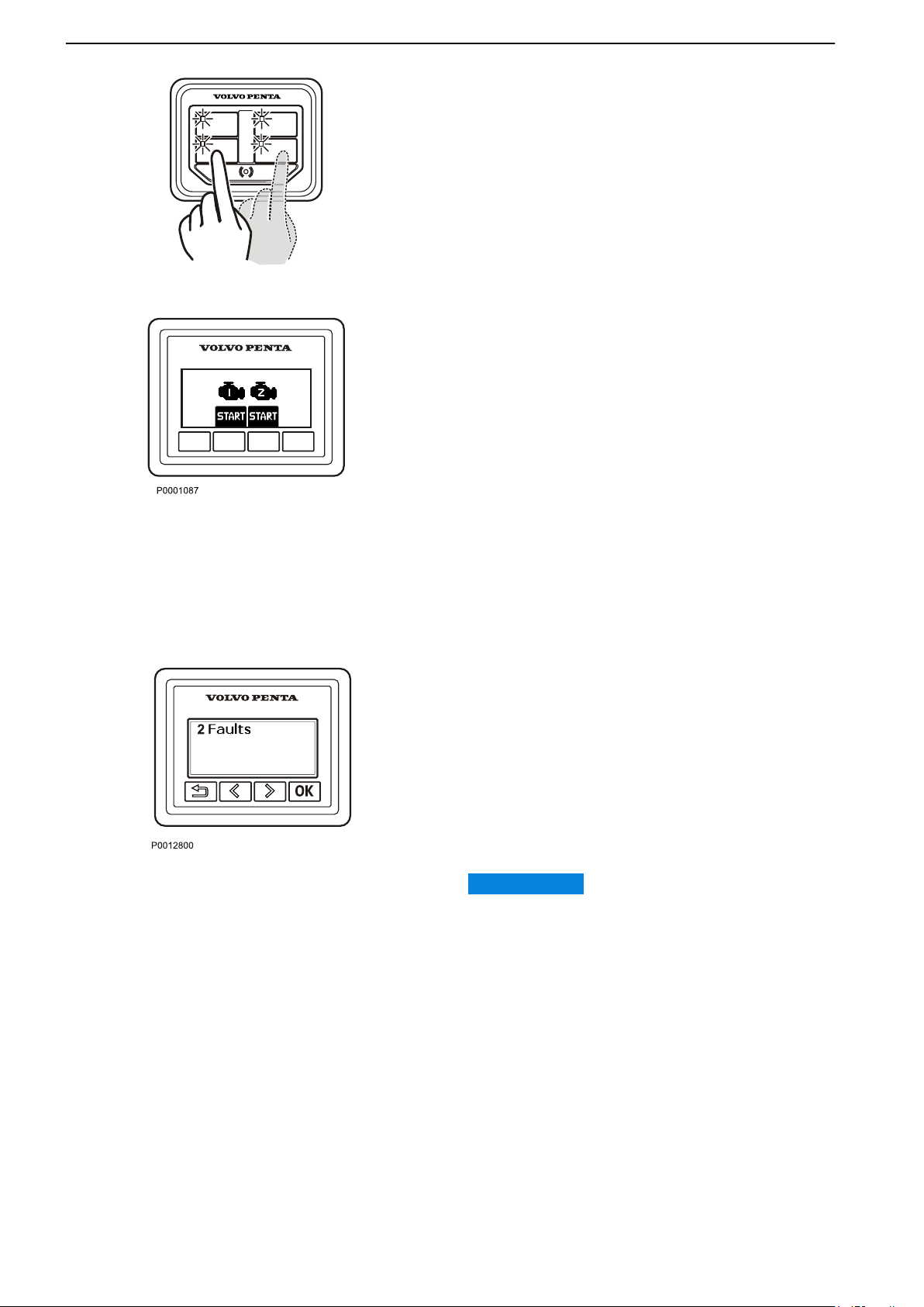
IGNITION IGNITION
START/STOP
START/STOP
P0016671
Starting
Starting Using the e-Key Panel
To
start, press the START/STOP button once for each
engine.
Starting Using the Start/Stop Panel
Press the START/STOP button for each engine.
Release
the button as soon as the engine has started.
Overheating protection
If the starter motor is engaged for its maximum
activation time (30 seconds), the starter motor circuit
is automatically cut to protect the starter motor from
overheating.
If possible, leave the starter motor to cool
for at least five minutes before making a new start
attempt.
Read the instruments and warm the
engine up
Allow the engines to idle for the first ten seconds.
Check that instruments and warning displays show
normal values.
Check
signs are showing. If a fault is registered, please refer
to section Fault Handling, page 67 for further
information and recommended actions.
Warm the engine up at low speed and low load, so
normal operating temperature is reached before full
power is used.
Never race the engine when it is cold.
Racing the engine when it is cold may damage the
engine
that no messages are displayed and no warning
IMPORTANT:
components and decrease the engine lifetime.
58 47708085 11-2016 © Bukh
Page 58
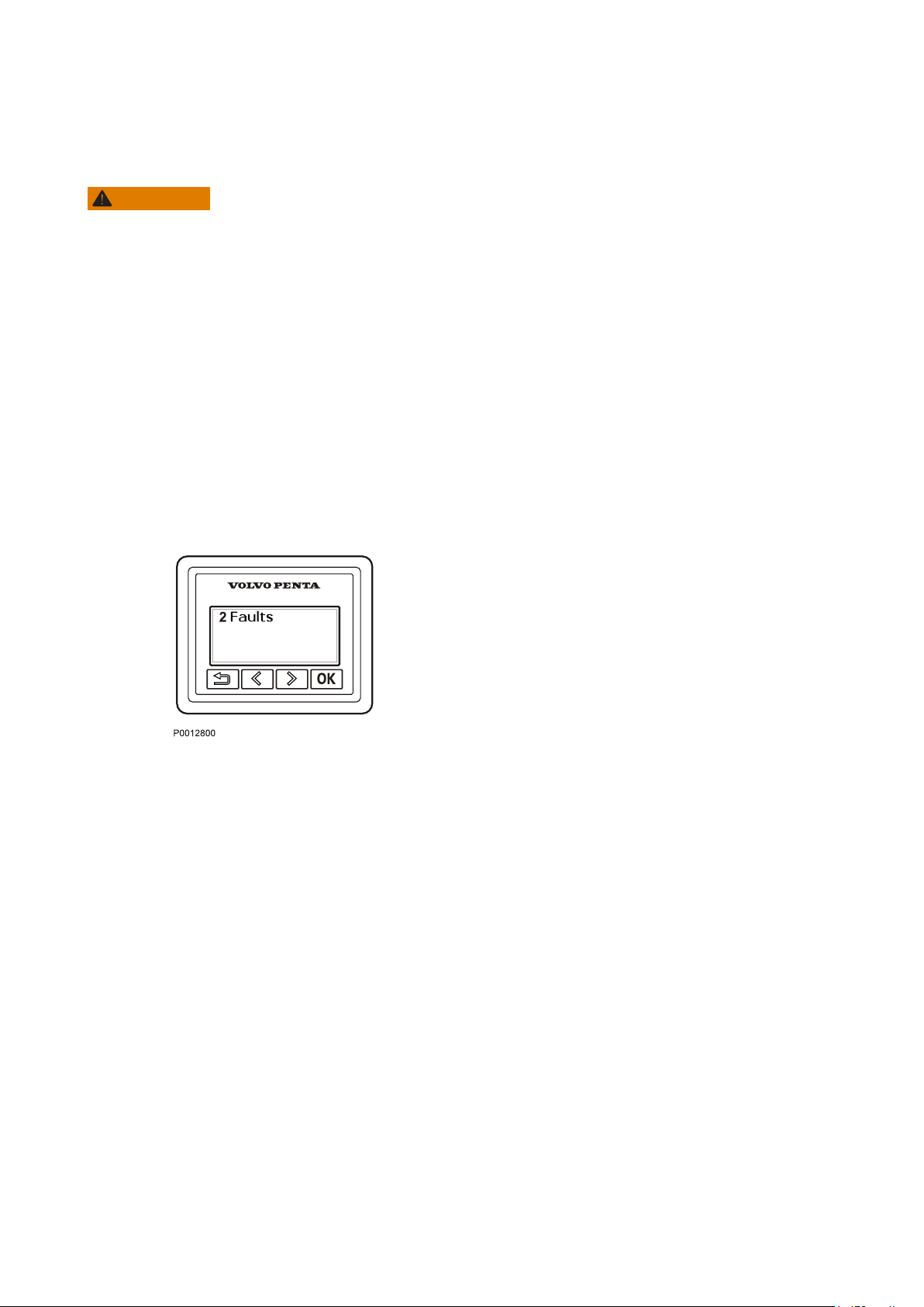
Operation
Learn to handle the engine, controls and other equipment in a safe and proper manner before casting off on your
maiden voyage. Remember to avoid sudden and extreme rudder maneuvers and gear shifts. There is a risk for
passengers and crew falling over or falling overboard.
WARNING!
A
rotating propeller can cause serious injury. Check that nobody is in the water before engaging ahead or astern.
Never drive near bathers or in areas where people could be in the water.
Reading the Instruments
Read all instruments and alarm displays directly after
starting, and then regularly during the voyage.
Alarms
Alarms and messages are shown in the information
display; some alarms do also have a sound alarm. If
an alarm instrument is installed, the lamp in question
will flash.
1
Read the message.
2 Acknowledge the alarm by pressing OK.
3 Take the indicated actions; see chapter Fault Code
Register, page 71.
The fault will be stored as long as the fault remains. It
will be possible to read out the fault code at an
upcoming service.
47708085 11-2016 © Bukh 59
Page 59
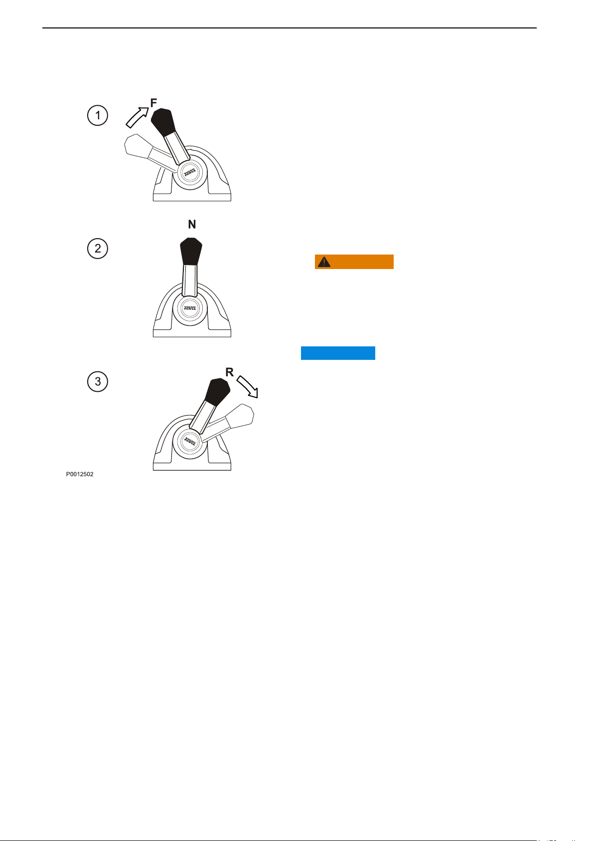
Operation
Maneuvering
Shifting
Shifting at higher engine speeds can be uncomfortable
for passengers and cause unnecessary stress on the
transmission or cause the engine to stop.
If you attempt to shift gear at a high engine speed, a
safety function is automatically activated, and will
delay shifting until engine speed has fallen to 1000
rpm.
Execute a Forward/Reverse Operation as Follows:
1 Reduce engine speed to idle and let the boat, more
between forward and reverse is done at idling.
or less, lose way.
WARNING!
Never shift to reverse when the boat is planing.
2
Move the control lever to Neutral (N) with a rapid,
distinct movement. Make a brief pause.
3 Move the control lever to Reverse (R) with a rapid,
distinct movement and increase engine speed.
IMPORTANT:
To avoid water entering the stationary engine via the
exhaust
during reverse maneuvers.
pipe, it is important that all engines are running
60 47708085 11-2016 © Bukh
Page 60
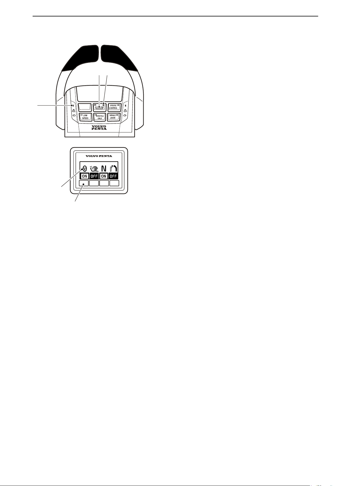
1
2
3
2
3
P0012976
Operation
Helm Station Change
1
Move the control lever(s) to neutral (N).
The neutral lamp (1) on the control lights up when
the drive is in neutral.
2 If the helm station is locked, unlock it by pressing
the STATION button (2). The padlock icon light (3)
is switched off, indicating that the station is
unlocked.
3 Activate the helm station being occupied by
pressing the STATION button (2).
The lamp in the control button will light up when the
helm station is active.
If the helm station is inactive, the lamp will be switched
off.
If the padlock icon (3) flashes, the helm station cannot
be activated. Another helm station is active and locked,
or unlocked with a drive selected (not in neutral).
Locking/Unlocking Helm Stations
If a helm station is locked, it will only be possible to start
and stop the engine or change helm stations from the
locked helm station.
Lock or unlock an active helm station by pressing the
STATION button (2).
The padlock icon (3) lights up when the helm station is
locked.
47708085 11-2016 © Bukh 61
Page 61
Operation
Cruising Speed
For best fuel economy operations at full speed must be
avoided. We recommend a cruising speed that is at
least 10% below the maximum engine revolutions at
top speed (full throttle).
Depending on hull type, the choice of propeller, the
load and sea state etc., the maximum revolutions at
top speed may vary, but they should be within the full
throttle range; refer to Technical Data, page 128.
If the engine is unable to reach its maximum throttle
range, this may be due to a number of factors
mentioned in Fault Handling, page 70.
Select a propeller with greater pitch if actual engine
revolutions exceed the full throttle range. Contact your
Bukh dealer for advice.
Synchronizing Engine Speed
When driving with twin engines, both the operating
economy and comfort will be increased when the
engines are operating at the same engine speed (rpm).
When the synchronization function is activated, the
engine speed (rpm) of the starboard engine is
automatically adjusted to that of the port engine. The
synchronization function is activated automatically if
the following conditions are met.
1 The engine speed levers for both engines are in
(approximately) the same position.
2 The engine speed levers are in a forward position.
The synchronizer is disengaged as soon as the
conditions are no longer met or if the engines reach
maximum throttle.
62 47708085 11-2016 © Bukh
Page 62
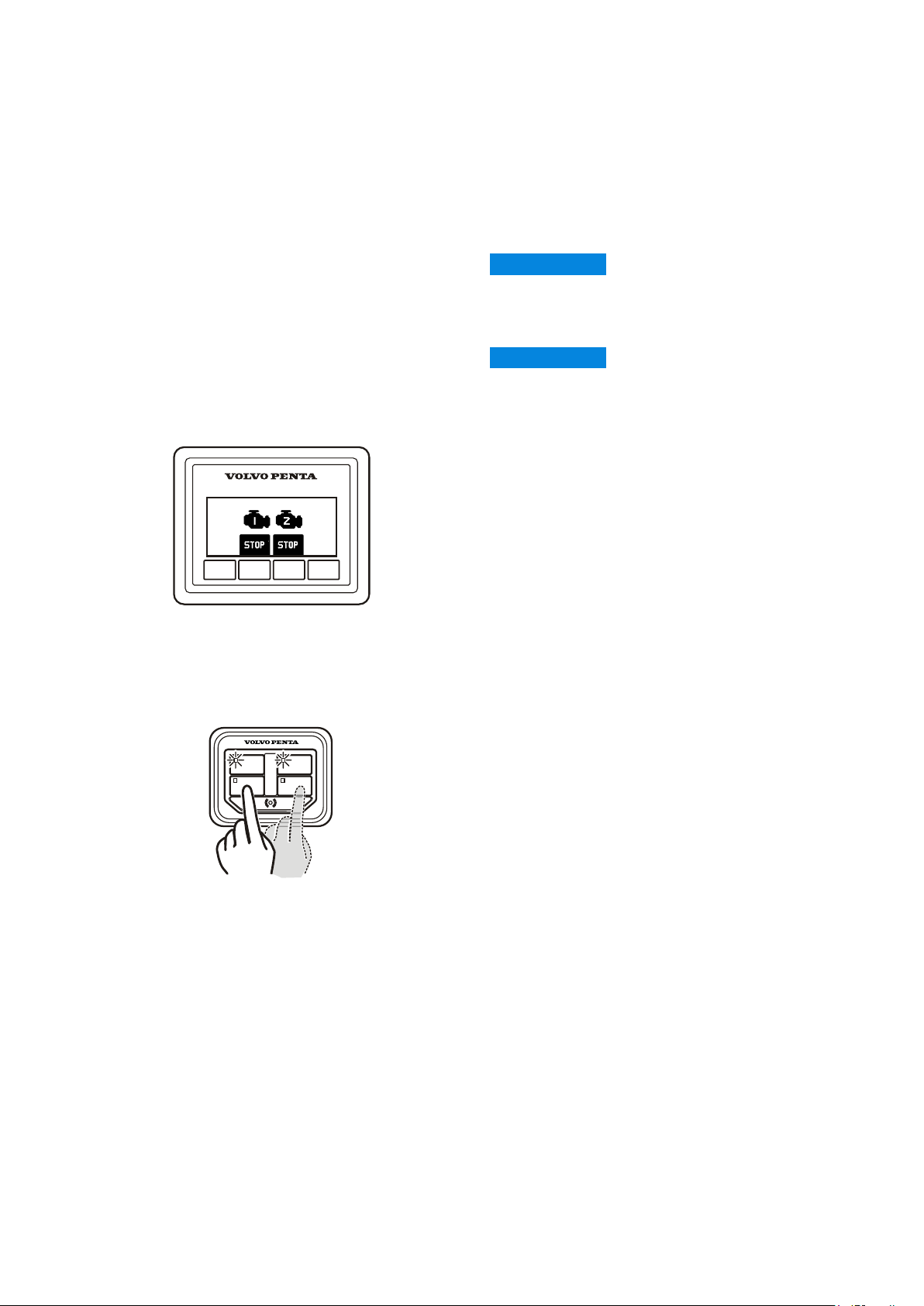
Engine Shutdown
IGNITION IGNITION
START/STOP
START/STOP
P0016518
P0013099
Allow the engine to run at low idle, in neutral, for a few minutes after operations are completed. In this way afterboiling is avoided at the same time as temperature equalization takes place. This is especially important when
the engine has been run at high rpm or under heavy load.
Stop the Engine
IMPORTANT:
Never disconnect the current using the main switches
when the engine is running.
The alternator and electronics could be damaged.
IMPORTANT:
Make sure the ignition is turned off before the main
switches
electronics could be damaged.
Stopping Using the Start/Stop Panel
1 Disengage the drive/reverse gear by putting the
2 Stop the engine(s) by pushing the START/STOP
are switched off. Otherwise the alternator and
control lever in neutral.
button(s).
Stopping Using the e-Key
1 Disengage
control lever in neutral.
2 Push the stop button(s). Release the button(s)
when the engine(s) has/have stopped.
Turn the ignition off and lock the EVC system
To turn the ignition of, press the IGNITION button.
The green lamp in the IGNITION button goes out to
indicate the ignition is off.
To lock the EVC system, hold the key fob in front of
the symbol on the e-Key panel.
A flashing red light indicates the system is locked.
the drive/reverse gear by putting the
47708085 11-2016 © Bukh 63
Page 63
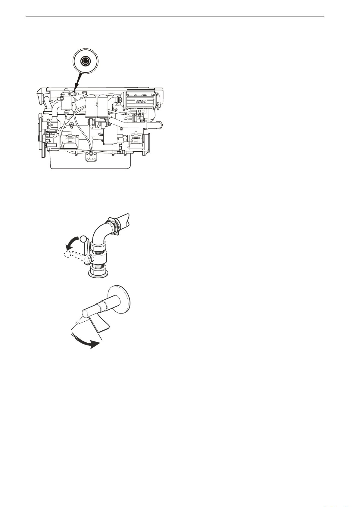
A
U
X
S
T
O
P
P0003709
0
P 5914000
Engine Shutdown
Auxiliary stop
the engine cannot be stopped in a normal procedure,
If
it is possible to stop the engine via the auxiliary stop
mounted on the side of the engine.
After Engine Shutdown
Check the engine and engine bay for leakages.
•
Close the fuel tap.
•
Close the sea cock where fitted.
•
Take an hour meter reading and carry out
•
preventive maintenance according to the
maintenance schedule.
Boats with stern drives: Trim the stern drive down to
•
maximum to protect the trim ram piston's untreated
surfaces from fouling.
If there is a risk of the boat striking bottom with the
stern drive, the drive must instead be trimmed up to
the maximum lift position.
Turn off the main switch before any long stoppage.
•
64 47708085 11-2016 © Bukh
Page 64
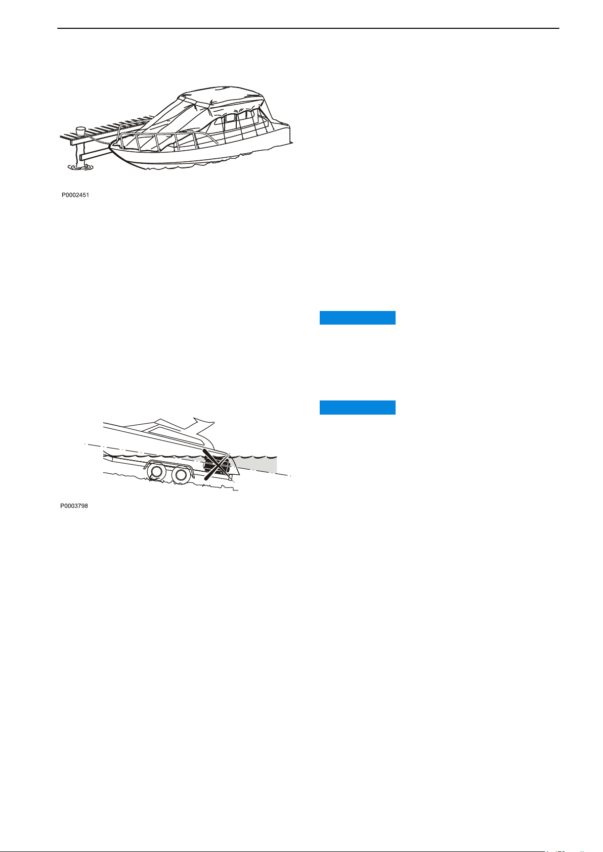
Engine Shutdown
Operation Break
Operation break with the boat in water
the boat is not used, but left in the water, the engine
If
must be warmed up at least once every fortnight. This
prevents corrosion damage in the engine.
If you expect the boat to be unused for two months or
more, it must be inhibited, please refer to
Storage, page 110.
Operation break with the boat out of water
Where boats are kept laid up on land when not in use,
there is a lower level of galvanic corrosion protection
due to oxidation on the sacrificial anodes. Before
launching the boat the sacrificial anodes on the drive
and shield must be cleaned with emery paper to
remove any oxidation.
If you expect the boat to be unused for two months or
more, it must be inhibited, please refer to
Storage, page 110.
IMPORTANT:
Use emery paper. Do not use a wire brush or other
steel tools when cleaning, as these may damage the
galvanic protection.
Laying Up and Launching
IMPORTANT:
If the boat submerges significantly below the static
waterline when it is laid up or launched there is a risk
of water entering the engine through the exhaust
system.
47708085 11-2016 © Bukh 65
Page 65
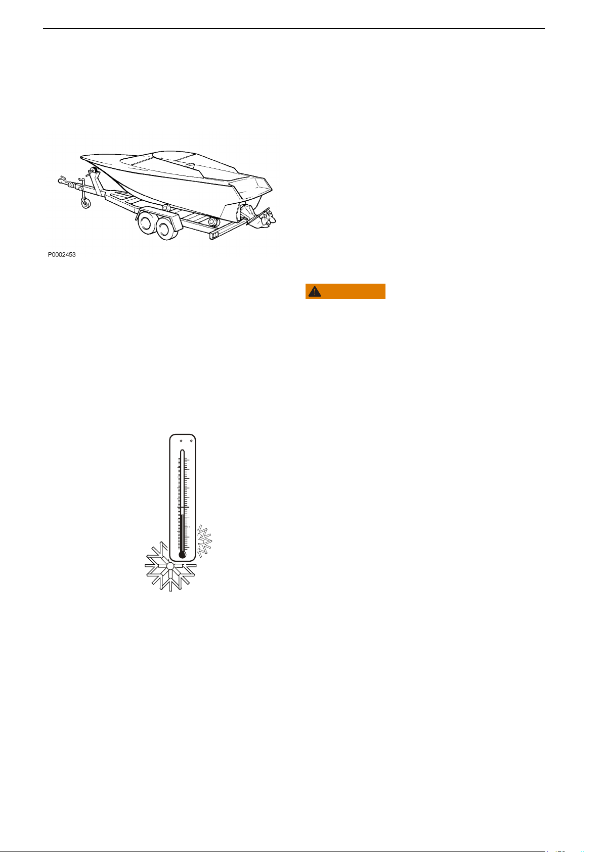
C
0
10
10
F
32
50
10
20
70
20
20
60
P0005905
Engine Shutdown
Trailering Your Boat
Check
local legislation in respect of boat transportation
by trailer - there are differences in various national
trailer regulations.
Boats with stern drives
Trim the stern drive up to its "lift position" (maximum
lift) before the boat is pulled onto the trailer for
transportation. It is possible to trim the stern drive
without starting the engine. When the stern drive has
reached the highest lift position an automatic catch
switches off the current to the trim pump. The catch is
released automatically when the stern drive is trimmed
down.
Always secure the stern drive in the up position with a
trailer kit (accessory) or similar so that it cannot fall
onto the trailer during transportation.
WARNING!
The engine must not be run with the drive in the “lift”
range.
Boats with reverse gear
Drain the water from the exhaust system to prevent
water entering the engine while the boat is being
transported by trailer.
Cold Weather Precautions
If the engine bay cannot be kept frost free, the sea
water system must be drained and the freshwater
system
prevent frost bursting; refer to Maintenance, page 97
and Seawater System, Draining, page 99
respectively for more detailed information.
Check the charge status of the battery. A poorlycharged battery can freeze and burst.
coolant must have sufficient frost protection to
66 47708085 11-2016 © Bukh
Page 66

Fault Handling
Despite regular maintenance according to the maintenance schedule and perfect operation conditions, faults that
need to be attended to during travel, may occur. This chapter describes some possible alarms and fault handling.
Note that the content of this chapter does not provide full coverage of the possible fault messages and alarms.
Contact a Bukh workshop for assistance with diagnostic readouts and unresolved faults.
NOTICE! The thruster is not a Bukh product. For assistance with faults regarding the thruster, please contact
the thruster supplier service center. If needed, contact your Bukh dealer for more information.
Alarm Handling
If a fault is discovered, the driver is warned via a
buzzing alarm and a message in the display.
Refer to Fault Code Register, page 71 for more
information regarding cause of fault and measures to
take.
The engine, transmission and EVC system are
monitored by the diagnostic function. Should the
diagnostics function discover a malfunction, it will
ensure continued operation by protecting the engine.
Depending on how serious the malfunction is, the
affect on the engine will vary.
Minor malfunction which does not damage the
•
engine or transmission.
Affect on engine: None.
Serious malfunction which will not immediately
•
damage the engine or transmission, e.g. high
coolant temperature.
Affect on engine: Engine power is reduced until
faulty value becomes normal.
Serious malfunction which will cause serious
•
damage to engine or transmission.
Affect on engine: Engine power is reduced.
Serious malfunction which makes it impossible to
•
control the engine or transmission.
Affect on engine: Transmission is disengaged and
engine speed is reduced.
Serious malfunction on transmission or in the engine
•
fuel injection system.
Affect on engine: Engine is stopped.
47708085 11-2016 © Bukh 67
Page 67
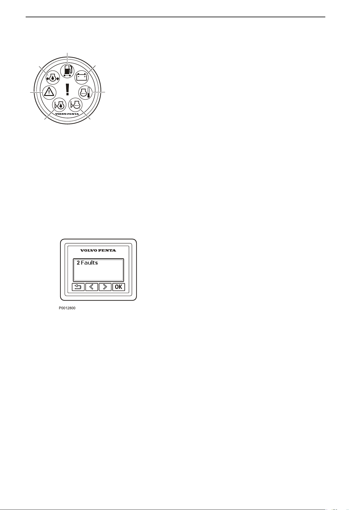
1
2
3
4
5
6
7
P0004761
Fault Handling
Alarm Display (Optional)
If a lamp in the alarm monitor flashes, it means a
malfunction has been detected.
1
If the orange Water in Fuel lamp is lit, there is too
much water in the water separator on the fuel
prefilter.
2 If the Charging lamp is lit, the alternator has
stopped charging.
3 If the Coolant Temperature lamp is lit, the coolant
temperature is too high.
4 If the orange Coolant Level lamp is lit during
operation, the coolant level is too low.
5 If the orange Oil Level lamp is lit during operation,
the engine oil level is too low.
6 If the red Warning lamp is lit during operation, a
serious malfunction has been detected.
If the orange Warning lamp is lit during operation
a malfunction has been detected.
7 If the red Oil Pressure lamp is lit during operation,
the engine oil pressure is too low.
Acknowledge message
1 Push OK to acknowledge the alarm. The buzzer will
become silent.
2 Read the message.
3 Push OK again and the message will disappear.
The alarm must be acknowledged before the engine
can be started.
68 47708085 11-2016 © Bukh
Page 68
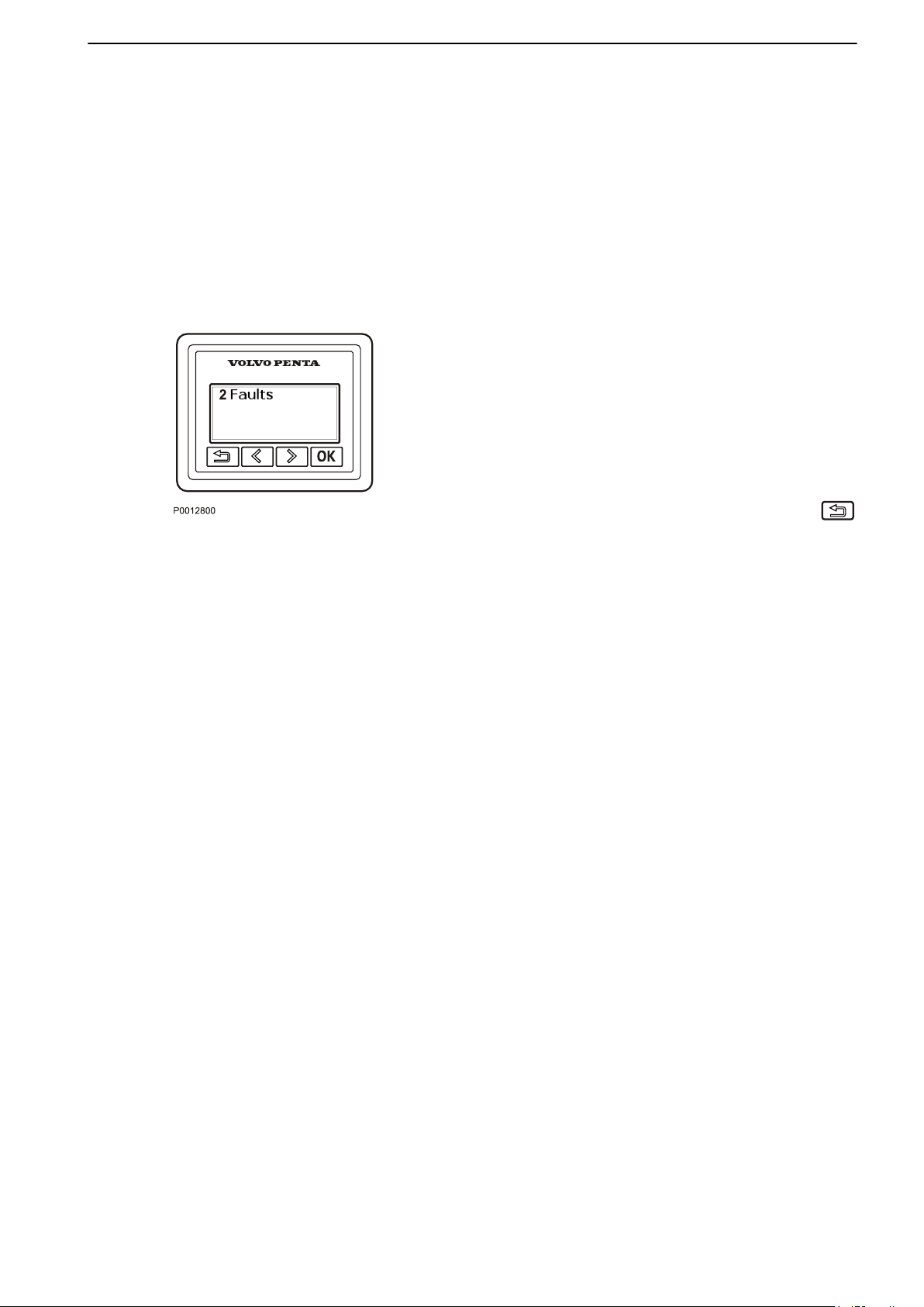
Fault Handling
Faults List
NOTICE!
In Glass Cockpit Displays, the faults are listed in
Warning Manager. For information about how to deal
with the fault messages in Warning Manager, see the
integrated Glass Cockpit Operator`s Manual. Go to
Info > Owner`s Manual to see the manual in the
display or download the latest manual on
www.garmin.com.
Information Display
The number of registered faults is displayed in the
Information Display.
1 Press the
2 If more than one fault is registered, use the arrow
buttons to browse through the fault list.
3 Press the OK
the cause of the fault and the corrective action.
4
Return to the previous menu by pressing the
button.
Deleting Faults From the List in Information
Display
Acknowledged faults are automatically deleted from
the fault list when the ignition is turned off. Stop the
engine and check that the ignition is turned off at all
helm stations. The faults are still stored in the system
and can be accessed via diagnostic readout by a Bukh
workshop.
When system power is reconnected, any remaining
faults are displayed on the screen.
Faults that have not been remedied must be
acknowledged every time system power is switched
on.
OK button to navigate to the submenu.
button twice to see information about
47708085 11-2016 © Bukh 69
Page 69

Fault Handling
Fault Tracing
A number of symptoms and possible causes of engine malfunctions are described in the table below. Always
contact your Bukh dealer if problems occur which you can not solve by yourself.
Read through the safety advice for care and maintenance work in chapter Safety precautions for maintenance
and service operations before starting work.
Symptoms and possible causes
Pop-ups are shown in the tachometer display See chapter Fault Code Register
Starter motor not turning (or slow) 1, 2, 3, 24
Engine does not start 3, 4, 5, 6, 7, 24
Engine starts but stops again 6, 7, 24
Engine difficult to start 4, 5, 6, 7
Engine does not reach correct speed at wide open
throttle (WOT)
Engine knocks 4, 5, 6, 7
Engine runs unevenly 4, 5, 6, 7, 10, 11, 17, 18, 20
Engine vibrates 15, 16
High fuel consumption 8, 9, 10, 12, 15, 21
Black exhaust smoke 10
Blue or white exhaust smoke 12, 21, 22
Low oil pressure 13, 14
Engine coolant temperature too high 17, 18, 19, 20, 21
No charge or poor charge 2, 23
5, 6, 7, 8, 9, 10, 11, 15, 18, 19, 20, 21, 24
1. Flat batteries 13. Lubricating oil level too low
2. Poor contact/open circuit in cables 14. Blocked oil filter
3. Fuse tripped or faulty relay 15. Defective/incorrect propeller
4. Lack of fuel 16. Defective engine mounting
5. Fouled fuel filter 17. Too little coolant
6. Water/contaminants in the fuel 18. Blocked seawater intake/pipe/filter
7. Leakage in the fuel system 19. Circulation pump drive belt slipping
8. Boat abnormally loaded 20. Defective impeller
9. Fouling on underwater hull/propulsion unit/
propeller
10. Insufficient air supply 23. Alternator drive belt slipping
11. Engine coolant temperature too high 24. Stored diagnostic fault codes
12. Engine coolant temperature too low
21. Defective/incorrect thermostat
22. Lubricating oil level too high
The codes can only be read and erased by a
service technician.
70 47708085 11-2016 © Bukh
Page 70
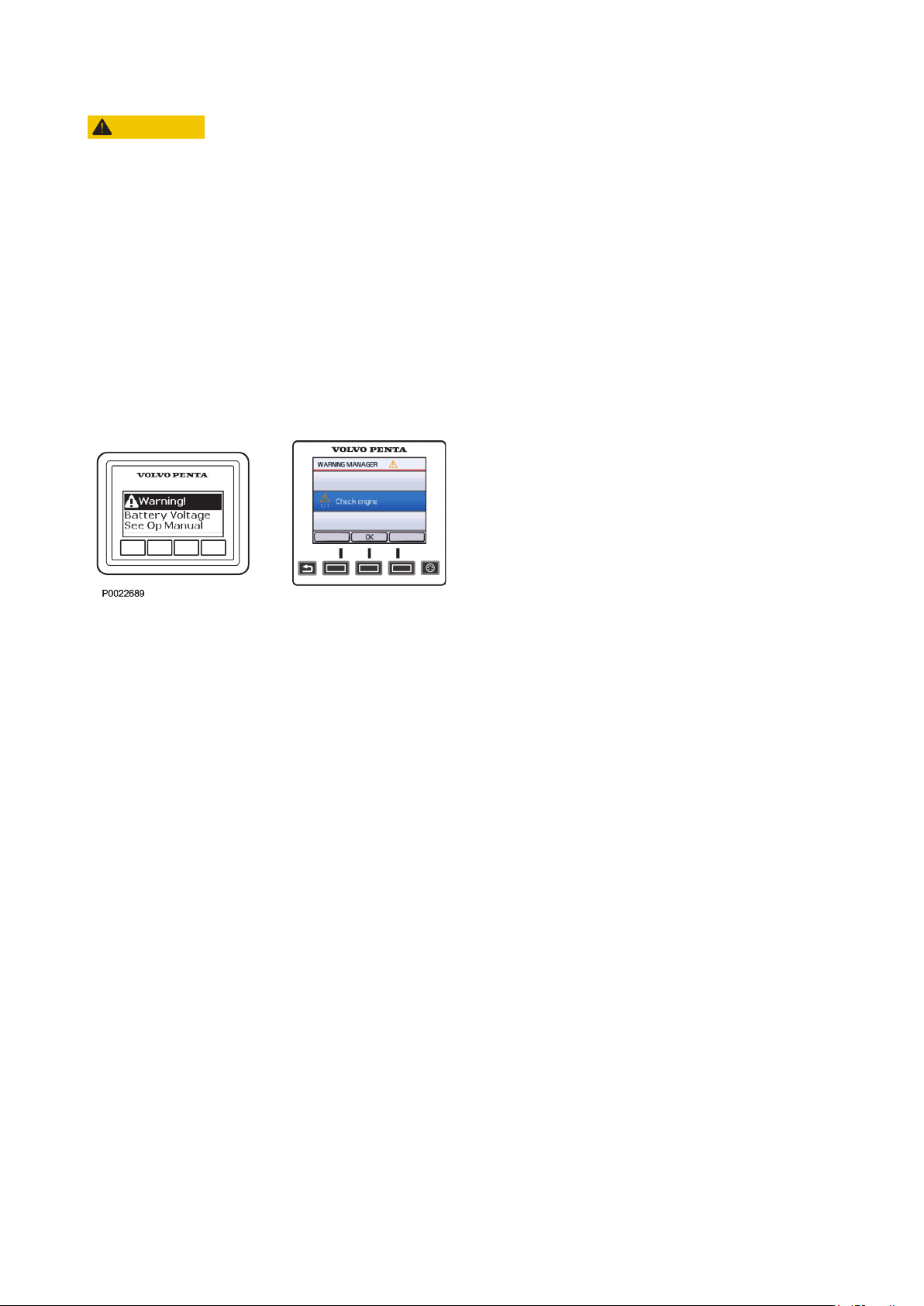
Fault Code Register
CAUTION!
Read the safety precautions for maintenance and service in the Maintenance Safety Information chapter before
starting work.
When a malfunction is discovered, the helmsman is warned by a sound alarm and a message is concurrently
shown in the display.
This chapter gives a more detailed description of the messages together with suggested actions to take.
Contact your Bukh dealer if the fault remains after trying the corrective actions associated with the fault.
Message
If
a malfunction is discovered, a message is shown on
the display. The message is presented in the list below
together with a description of how the system might be
affected and suggested actions to take.
Thruster fault messages
NOTICE! The thruster is not a Bukh product. For
assistance with faults regarding the thruster, please
contact the thruster supplier service center. If needed,
contact your Bukh dealer for more information.
47708085 11-2016 © Bukh 71
Page 71

Fault Code Register
Emergency Stop Switch
Reset the external stop button.
Battery Voltage
Possible cause: The alternator output voltage is too low.
Corrective action: • Check the battery. Refer to Battery, page 105.
•
Check belt tension. Refer to Drive Belt, Check and Change, page 92.
Can Not Start, Trim Too High
Possible cause: • The drive is tilted too high.
• Trim sender failure.
Corrective action: It is possible to override the immobilizer by pressing the start button for 5 seconds and
then stop pressing the button.
Check Control Lever
Possible cause: • Shift and throttle incorrect.
•
Slip function not available.
Corrective action: Acknowledge the fault by moving the control to Neutral and press the OK button. Engine power
is reduced and the gear is automatically set to Neutral.
Check Engine
Possible
cause:
Corrective
action:
• Battery voltage is incorrect.
•
The fuel pressure is incorrect. Engine performance might be affected.
• Communication failure automatically sets the gear to Neutral. Engine performance might
be affected.
• The oil pressure is too low and the engine power is reduced.
• Check the battery. Refer to Battery, page 105.
• Check the oil level and that there is no leakage. Refer to Oil level, checking and topping
up, page 94.
Check EVC System
Possible cause: • Limited or no steering.
•
Shift and throttle are unavailable and the gear has automatically been set to Neutral as
engine power is reduced and the helm station has lost communication with the engine.
• Control panel failure.
Corrective
action:
72 47708085 11-2016 © Bukh
• Use alternative helm station if possible.
• Check if any buttons are stuck.
Page 72

Fault Code Register
Check Joystick
Possible cause: Joystick failure.
Corrective action: Check if any button has stuck. Use steering wheel or choose alternative station.
Check Multilink
Possible causes: Limited instrumentation — the control unit has a communication fault.
Corrective action: Contact your Bukh workshop.
Check transmission
Possible
cause:
Corrective
action:
• The gear is automatically set to Neutral and it is not possible to shift the gear until the fault
has been acknowledged.
• The gear shift is malfunctioning.
•
The slip function is limited.
• Lowspeed is not available.
• Transmission oil pressure is not available.
• Transmission oil temperature is not available.
• The engine is automatically emergency stopped.
• Acknowledge the fault by moving the control to Neutral and press the OK button.
• Check transmission oil level.
Check Shift Actuator
Possible cause: The gear shift is unavailable.
Corrective action: Acknowledge the fault by moving the control to Neutral and pressing the OK button.
Check Steering Wheel
Possible cause: Steering is limited or unavailable.
Corrective action: Contact your Bukh workshop.
Coolant Level
Possible cause: The coolant level is too low. The sensor cable is disconnected.
Corrective action: • Check the coolant level and also check for leakage. Refer to Coolant Level, Checking
and Topping Up, page 98
• Check the sensor cable connection.
47708085 11-2016 © Bukh 73
.
Page 73

Fault Code Register
Coolant Pressure
Possible
cause:
Corrective
action:
The coolant pressure is too low.
• Check the coolant level. Refer to Coolant Level, Checking and Topping Up, page 98
• Check that the seawater filer is not blocked. Refer to Seawater Filter, Check and
Cleaning, page 102.
• Check the impeller in the seawater pump. Refer to Impeller, Check and
Change, page 100.
• Check that there is no leakage.
Coolant Temperature
Possible
cause:
Corrective
action:
The coolant temperature is too high.
• Check the coolant level. Refer to Coolant Level, Checking and Topping Up, page 98.
•
Check that the seawater filter is not blocked. Refer to Seawater Filter, Check and
Cleaning, page 102.
• Check the impeller in the seawater pump. Refer to Impeller, Check and
Change, page 100.
.
• Check that there is no leakage.
Engine Oil Filter
Possible cause: There is an oil pressure difference and engine power is reduced.
Corrective action: Contact your Bukh workshop.
Engine Oil Level
Possible
cause:
Corrective
action:
The oil level is too low.
NOTICE!
In rough
is too low. If this happens, acknowledge the fault, and perform corrective actions just in case.
following seas or head seas, the system may incorrectly sense that the engine oil level
• Check the engine oil level. Refer to Oil level, checking and topping up, page 94.
• Check that there is no leakage.
74 47708085 11-2016 © Bukh
Page 74

Engine Oil Pressure
Possible cause: Oil pressure is too low and the engine power is reduced.
Fault Code Register
Corrective action: • Check the engine oil level. Refer to Oil level, checking and topping up, page 94
• Check that there is no leakage.
Engine Oil Temperature
Possible cause: The engine oil temperature is too high and the engine power is reduced.
Corrective action: • Check the oil level. Refer to Oil level, checking and topping up, page 94.
•
Check that there is no leakage.
Engine Speed
Possible cause: Engine performance may be compromised and engine power is reduced.
Corrective action: Contact your Bukh workshop.
Exhaust Temperature
Possible cause: The exhaust temperature is too high and engine power is reduced.
Corrective action: Contact your Bukh workshop.
Fuel pressure
.
Possible cause: The fuel pressure is too low.
Corrective action: • Check the fuel level.
• Check that there is no fuel leakage.
• Check that the fuel filters are not blocked. refer to, Maintenance, page 95.
Fuel Temperature
Possible cause: The fuel temperature is too high.
Corrective action: • Check the fuel level.
• Check that there is no fuel leakage.
Helm Restarted
Possible cause: The engine has lost communication with a helm station and engine power is reduced.
Corrective action: The helm station is automatically restarted.
47708085 11-2016 © Bukh 75
Page 75

Fault Code Register
Intake Manifold Temperature
Possible cause:
Charge air temperature is too high and engine power is reduced.
Corrective action:
Contact your Bukh workshop.
Key Failure
Possible cause: A button on the e-Key panel is pressed down.
Corrective action: Verify that the button is not pressed down.
Power Trim Faults
Possible cause: Drive unintentionally moved in. Not possible to control the power trim.
Corrective action: Verify power trim angle before you continue your journey.
Refer to In Case of Emergency, page 85.
Primary Battery
Possible cause: Poor batteries or poorly charged batteries.
Corrective action: Change or charge batteries. Refer to Battery, page 105.
Secondary Battery
Possible cause: Poor batteries or poorly charged batteries.
Corrective action: Change or charge batteries. Refer to Battery, page 105.
Sensor Failure
Possible cause: A sensor failure may be affecting engine performance.
Corrective action: Contact your Bukh workshop.
Steering failure
Possible cause: The helm station has lost communication with the steering actuator.
Corrective action: Please contact a Bukh workshop.
Steering Oil High Temp
Possible cause: The temperature on the steering oil is to high.
Corrective action: Check hydraulic steering oil cooling system. refer to Maintenance, page 109.
76 47708085 11-2016 © Bukh
Page 76

Fault Code Register
Steering Oil Low Temp
Possible cause: If the temperature of the steering oil is below 5°C (41°F) a message will be displayed every
thirty seconds until the oil reaches normal operating temperature.
Water in Bellows
Possible cause: Water in bellows.
Corrective action: Inspect bellows.
Water in Fuel
Possible cause: Water has entered the fuel filter(s).
Corrective action: Empty the water trap underneath the fuel filters. Refer to Maintenance, page
95.
47708085 11-2016 © Bukh 77
Page 77

In Case of Emergency
Despite regular service in accordance with the planned maintenance schedule and perfect operating conditions,
faults may occur that must be remedied before the boat can continue its trip. This chapter provides advice on how
to remedy a number of conceivable faults.
When certain faults occur safety functions engage to protect the engine. The following may occur:
• Engine cannot be started.
• The gear is in neutral and engine speed is limited
• The engine stops
If a fault occurs, confirm any fault alarm and take the necessary measures. Refer to this section and Fault Code
Register, page 71.
Running Aground
The automatic kick-up function releases the drive in the
event of running aground or colliding with an object in
the water. If the function has been triggered and the
drive has kicked up, it must be trimmed back to its
original position using the control buttons.
The kick-up function only protects the drive when
travelling forwards. There is no protection for the drive
when travelling backwards.
After running aground, check that the drive and
propeller are not damaged and that the drive does not
vibrate. If there is damage/vibration, the boat should
be driven (if possible) slowly to a harbor and lifted out
of the water.
Lift the boat ashore. Check the oil level in the drive. If
the oil is gray-colored, water has entered and the drive
must be inspected by an authorized Bukh workshop.
The same applies if there is damage to the drive.
Replace the propeller if it is damaged.
To prevent galvanic corrosion, any paintwork damage
on the drive and propeller shall be repaired before
launching the boat again.
Checking the tie rod
Check the tie rod that holds the drive together if you
have run aground.
If the tie rod is bent, loose or damaged, it must be
checked immediately by an authorized Bukh
workshop. Steer the boat to a harbor at low speed.
WARNING!
If the parallel strut (tie bar) shows signs of damage, run
at reduced speed to harbor. The parallel strut is a vital
safety component, damage may effect steering
characteristics. In the worst case steering could be lost
altogether. Never align or weld a damaged parallel
strut. Please contact your nearest authorized Bukh
workshop for assistance.
78 47708085 11-2016 © Bukh
Page 78
P0002107
In Case of Emergency
Starting Using Auxiliary
Batteries
WARNING!
Explosion hazard. Batteries contain and give off an
explosive gas which is highly flammable and
explosive. A short circuit, open flame or spark could
cause a violent explosion. Ventilate well.
WARNING!
confuse the positive and negative poles on the
Never
batteries. Risk of arcing and explosion.
1 Check that the auxiliary battery has the same
voltage as the engine system voltage.
2 Connect the red positive cable to the plus (+)
terminal on the discharged battery and then to
the plus terminal on the auxiliary battery.
3 Connect the black start cable to the minus (–)
terminal on the auxiliary battery and to a place
a little distance away from the discharged
battery, e.g. the start motor's negative terminal.
WARNING!
Under no circumstances may the black jumper
cabel (–) come in contact with the positive
connection on the starter motor.
4
Start the engine and let it run at fast idle for
approximately 10 minutes to charge the
batteries. Make sure there is no extra equipment
connected to the electrical system.
WARNING!
Working with or approaching a running engine is a
safety risk. Watch out for rotating components and
hot surfaces.
WARNING!
Do not touch the connections during the start
attempt: Risk of arcing.
Do not bend over any of the batteries either.
Turn off the engine. Remove the start cables in
5
the exact opposite order to their connection.
47708085 11-2016 © Bukh 79
Page 79
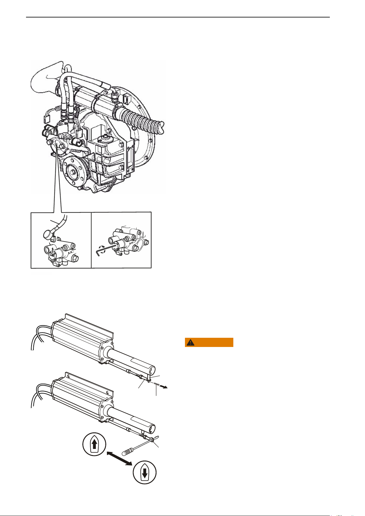
P0024013
2
3
A
A
A
B
3
1
2
2
P0006565
In Case of Emergency
Emergency Shifting
If
a fault occurs that prevents engaging gears with the
control lever (shifting), it is possible to engage them
manually.
Manual shifting of gears
1 Stop the engine and turn off the ignition. If the boat
is equipped with an ignition switch lock, take the key
out of the switch lock.
2 Look for the “A“ and “B“ markings on the cable for
the reversing gear shift solenoid valves. Use a
screwdriver to pry off the black protective shroud
enclosing the electrical connections to the solenoid
valve. Then disconnect the white connector from
the solenoid valves (2).
3 Normally the “A“ side is set for forward motion in a
single installation, and in a dual installation it is set
for forward motion from the starboard engine. Insert
a 2 mm Allen key into the "A" connection (3), then
tighten the solenoid valve emergency screw at least
5 turns clockwise.
4 Now the gear operation has been activated for
forward movement. Switch on the ignition. Fault
codes can now come from the EVC system, which
is normal as the shift solenoid valves are
disconnected.
NOTICE! Forward gear is now permanently activated
and cannot be disengaged by the control lever. Adjust
your speed accordingly!
Emergency Shifting, Drive
If a fault occurs which prevents the drive from being
operated (shifted) with the control lever, it is possible
to shift manually, using the description below.
WARNING!
In emergency shifting, the unit is locked in forwards
operation. Please note that the drive can not then be
disengaged
only be cut off by stopping the engine with the ignition
key or stop button..
Manual drive engagement
with the control lever. Forward motion can
1 Stop the engine and take the starter key out of the
starter switch.
2 Pull out the split pin (1) and lift the adapter (2) from
the pin (3).
3 Place a screwdriver or similar tool in the adapter (2)
hole and move the control wire horizontally.
80 47708085 11-2016 © Bukh
Page 80

In Case of Emergency
Emergency Steering
Emergency Alignment, Electrical
Rudder Actuator
Electrical Rudder Actuator is available for inboard
installations (reverse gear) with electrical steering.
If a fault occurs that prevents the electrical rudder
actuator from being operated with the steering wheel,
the electrical rudder actuator for straight forward
operation can be aligned manually using the
description in this chapter.
If
steering is out of order, align the rudder actuator and
use control levers to steer the boat.
The tools needed during this operation are supplied in
a special tool box together with the boat.
WARNING!
Working with or approaching a running engine is a
risk. Watch out for rotating components and hot
safety
surfaces.
The following procedure can be carried out with the
engines running, even though it is not recommended.
Wear hearing protection when in the engine room as
there is a risk of harmful sound levels.
47708085 11-2016 © Bukh 81
Page 81
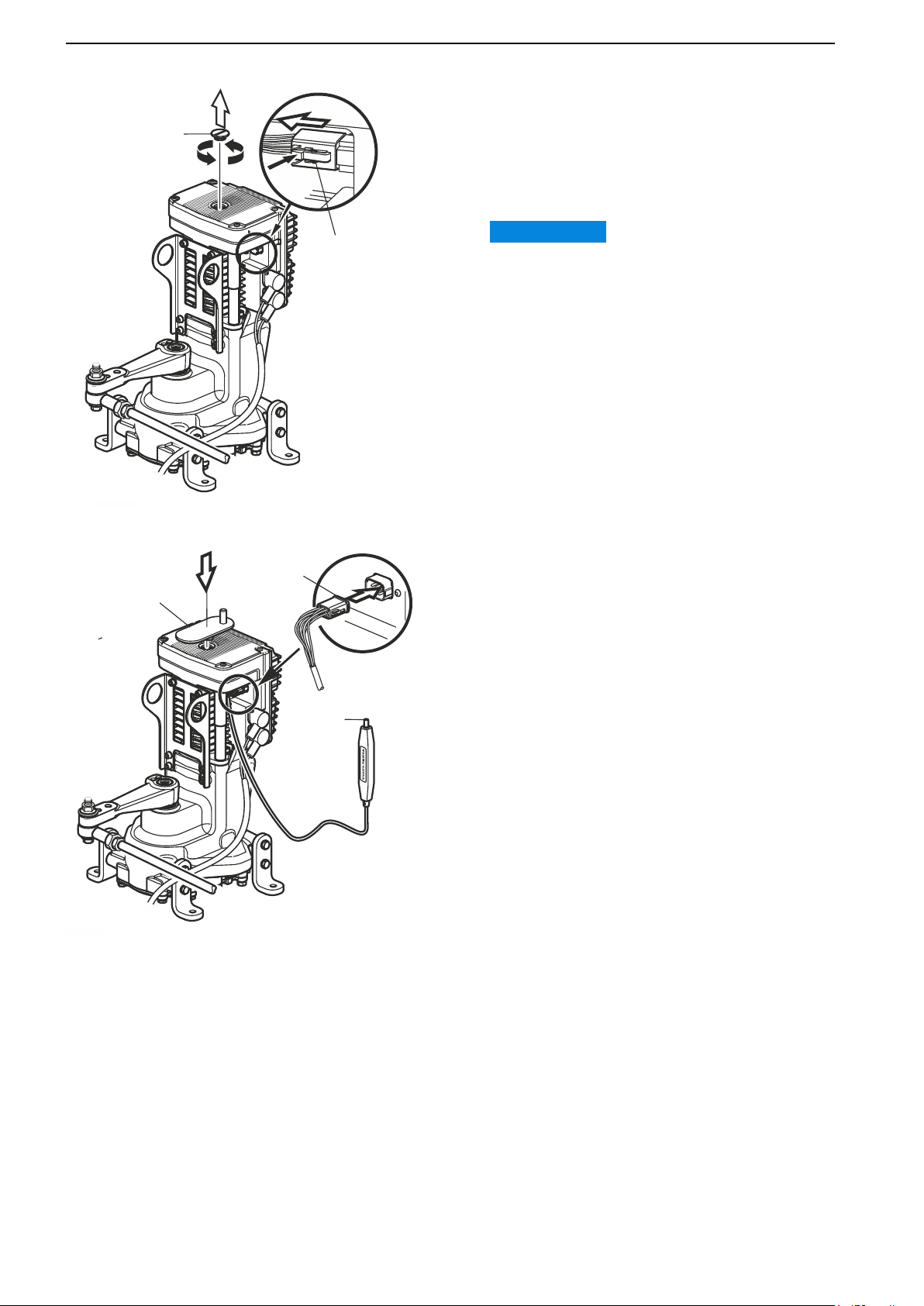
P 2261700
5
4
3
2
1
In Case of Emergency
1 Unscrew and remove the plug (1). Disconnect the
cable
by pressing down the lock (2) and at the same
time wiggle the connector in a forward position.
2 Connect the switch (3) and fit the crank tool (4).
3 Press down the switch button (5) and keep it
pressed while carefully turning the crank tool.
IMPORTANT:
Do
not force the crank tool beyond the end position,
it could damage the Electrical Rudder Actuator.
NOTICE! Do not use the crank tool while rampage.
82 47708085 11-2016 © Bukh
Page 82
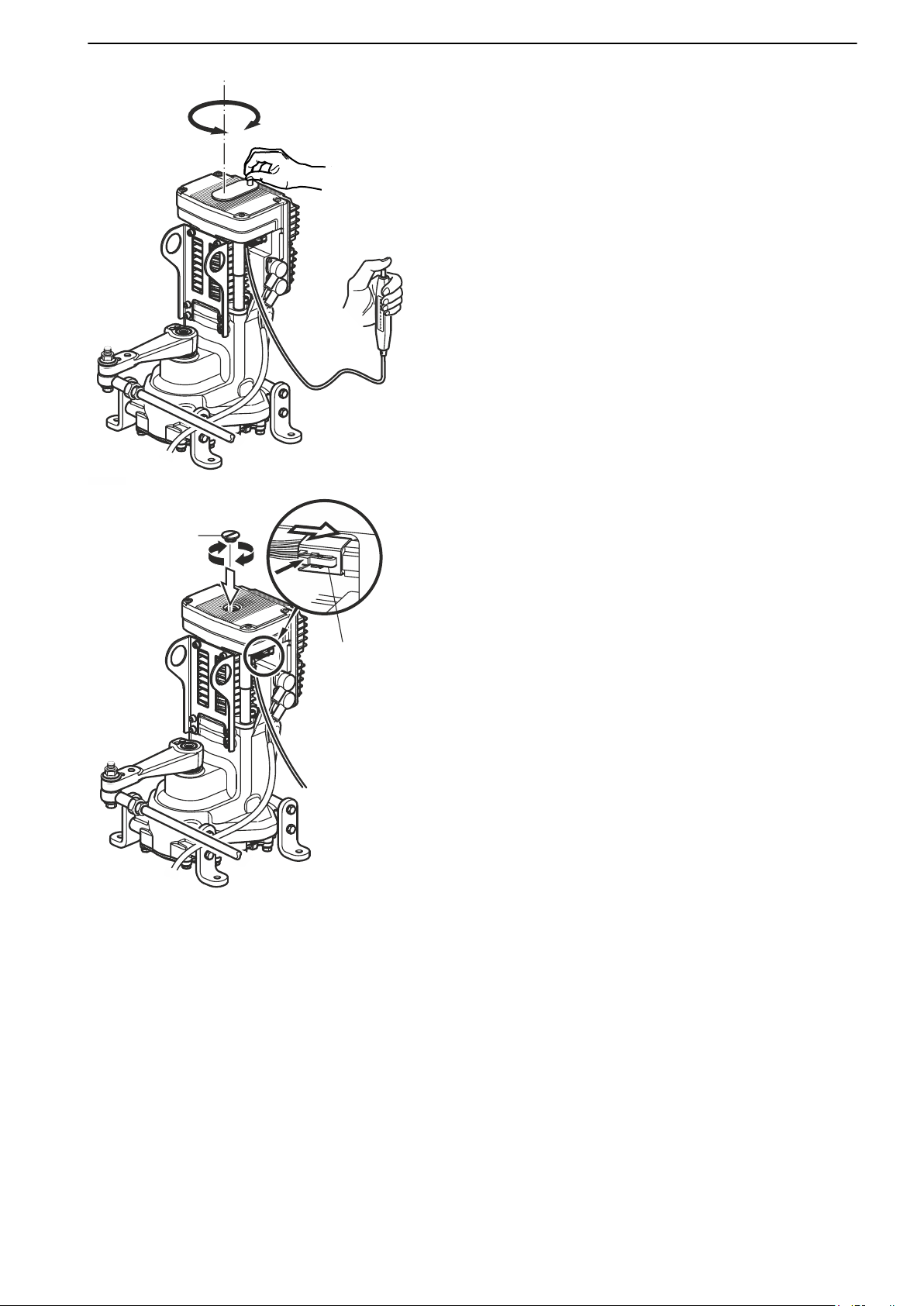
P 2261900
6
7
In Case of Emergency
4 Turn the crank tool until the steering arm(s) is
aligned for straight forward motion.
5
Remove the crank tool. Disconnect the switch by
pressing down the lock and at the same time unplug
the switch by slowly wiggling it.
Screw the plug (6) back on.
6 Reconnect the cable (7) disconnected in step 1.
47708085 11-2016 © Bukh 83
Page 83
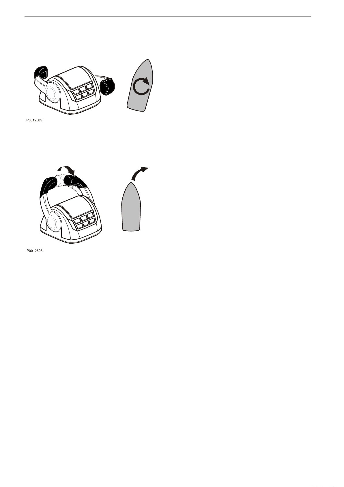
In Case of Emergency
Emergency steering with control
levers
If a fault occurs that prevents the Electrical Rudder
Actuator from being operated with the steering wheel,
the Electrical Rudder Actuator for straight forward
align
operation and use the steering method described
below to reach the nearest harbor.
Rotate the boat
Put one control lever in the position for forward and put
the other control lever in the position for reverse. Use
a suitable engine speed for maneuvering.
The direction of rotation is determined by the lever
which is put in the position for reverse. If the boat is to
move to starboard, the starboard control lever should
be put in the position for reverse.
Steering the boat
Put the control levers in forward. Use a suitable engine
speed for maneuvering.
The direction of the steering is determined by the use
of the control levers. If the boat is to turn to starboard,
reduce speed on starboard engine. The greater the
difference in speed between the control levers the
more the boat turns. To make a sharp turn, move one
of the control lever to reverse for a moment.
84 47708085 11-2016 © Bukh
Page 84
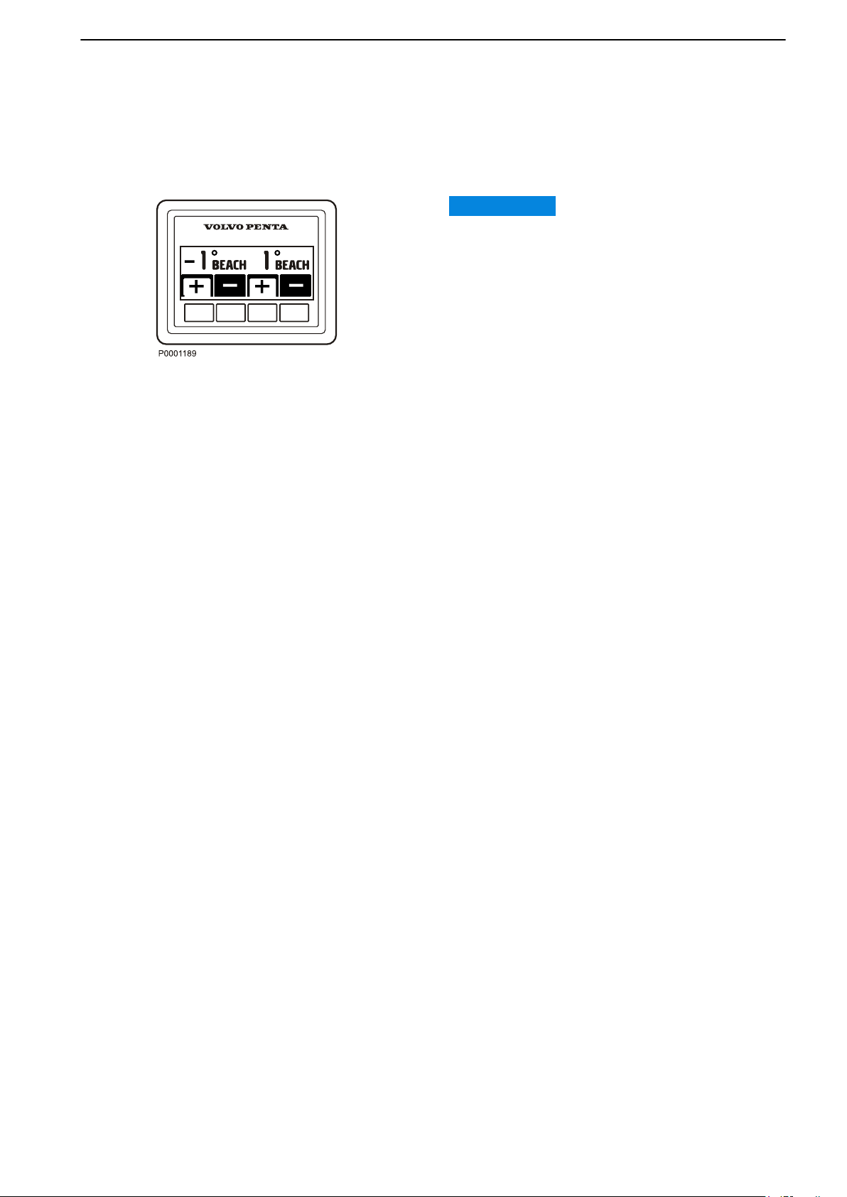
In Case of Emergency
Emergency Trimming
If a situation occurs that needs the drive to be trimmed
over the trim limit, the drive can be emergency
trimmed.
IMPORTANT:
When emergency trimming is performed, the
automatic
outside the trim ranges, this can damage the boat and
drive.
1 Press the trim button on the control or power trim
2 Press the button again and hold it depressed for
stop will not work. The drive can be trimmed
panel in the direction the drive needs to be
trimmed. Release the button when the trim limit
is reached.
more than 5 seconds. The drive starts trimming.
Start after crash-stop
If
the engine crash-stops, the following routine must be
performed before the engine can be started again.
1 Move control lever(s) to neutral.
2 Acknowledge any alarms and turn the ignition off.
3 Wait until the system is completely shut down and
all lamps are out.
4 Turn the ignitionon but do not start the engine.
5 Acknowledge any alarms. Start the engine.
47708085 11-2016 © Bukh 85
Page 85

Maintenance Schedule
Your Bukh engine and its equipment are designed for high reliability and long life. The engines are built to have
the smallest possible environmental impact. If preventive maintenance is carried out, according to the
maintenance schedule, these qualities will be retained and unnecessary malfunctions will be avoided. It is the
owner's responsibility to make sure that the services in the service intervals are performed in order for the warranty
to be valid.
NOTICE! For emission related warranty rights see Emission Control System Warranty Statement.
Service Intervals
Service intervals are shown below. The service content can be found in the Service Protocol available for
download at www.volvopenta.com.
The Operator’s Manual shows a selection of service points and how these should be carried out; also included
are points that must be checked/implemented between regular scheduled services or points that the user/owner
should be able to perform for reasons of safety in the event that anything unforeseeable should occur when under
way. All service and maintenance points can be found in the product’s Service and Maintenance Manual. Any
owner wishing to carry out some maintenance and service himself can purchase this manual. For products
covered by the warranty, please refer to the terms and conditions of the warranty with regard to documentation
of completed services.
Extended service intervals
The interval between engine oil changes may be extended in certain circumstances. To determine whether the
service interval may be extended, Volvo Penta's conditions for extended service intervals must be met and an oil
analysis performed. Contact your Bukh dealer for further information.
Where both operational and calendar times are specified, perform the maintenance item at whichever time is the
sooner.
In applications that include a reverse gear, the reverse gear manufacturer's service intervals must be complied
with.
A-E = Type of service (regular service)
Type A
Type B Service Every 400 hours of operation.
Type C Service Every 800 hours of operation.
Type D Service Every 800 hours of operation.
Service Every 200 hours of operation.
(Recommended every 12 months)
(Recommended every second year )
(Recommended every second year )
(Not applicable for inboard installations)
(Recommended every fourth year)
(Type C service for inboard installations)
Type E Service Every 2000 hours of operation.
(Recommended every fourth year)
(Type D service for inboard installations)
NOTICE! Make sure that the service book is stamped after each performed service.
86
47708085 11-2016 © Bukh
Page 86

Maintenance
This chapter contains general technical information and instructions on how the prescribed maintenance items
must be carried out. Read through the instructions carefully before starting work. The times when maintenance
items must be carried are indicated in the Maintenance Schedule, page 86.
Read through the safety precautions for maintenance and service in the Maintenance, page 90 chapter before
work on the engine is begun.
Bukh recommend that all servicing with the engine running should be undertaken by an authorized Bukh
workshop.
WARNING!
Care and maintenance work should be done with the engine stopped unless otherwise specified. Stop the engine
before opening or removing the engine hatch/hood. Make it impossible to start the engine by removing the start
key and cutting the system voltage with the main switches.
47708085 11-2016 © Bukh 87
Page 87
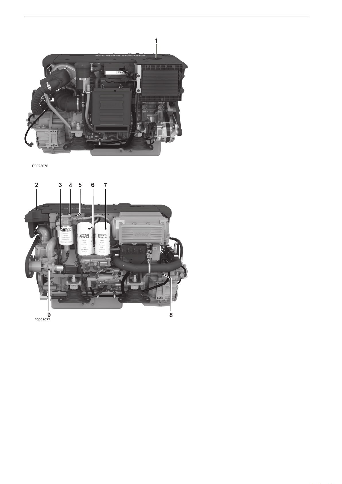
Maintenance
D4 with reverse gear, starboard 1 Oil filler cap, engine
2 Expansion tank
3 Fuel Filter
4 Auxiliary stop
5 Oil dipstick, engine
6 By-pass filter for engine oil
7 Oil filter
8 Oil dipstick, reverse gear
9 Seawater Pump
D4 with reverse gear, port
88 47708085 11-2016 © Bukh
Page 88
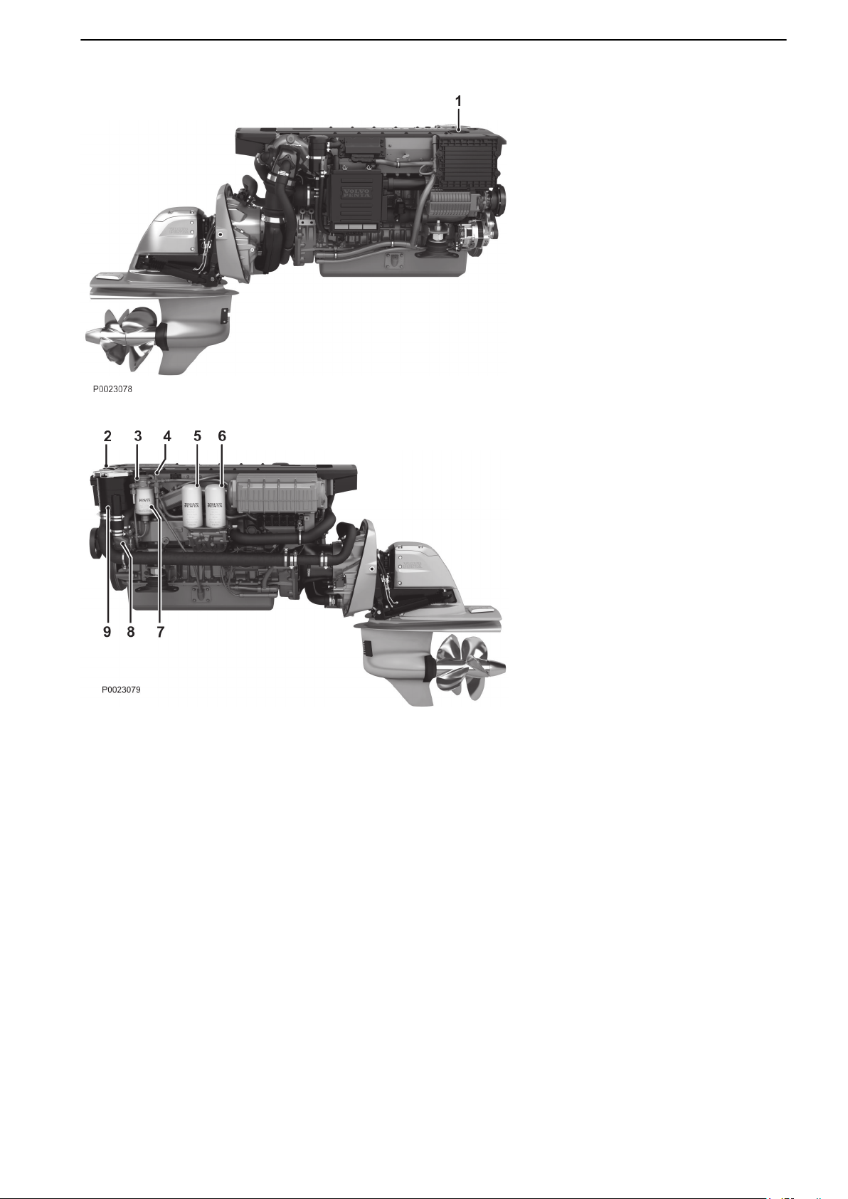
D6 with drive, starboard 1 Oil filler cap, engine
2 Expansion tank
3 Auxiliary stop
4 Oil dipstick, engine
5 By-pass filter for engine oil
6 Oil filter
7 Fuel Filter
8 Seawater Pump
9 Seawater filter
D6 with drive, port
Maintenance
47708085 11-2016 © Bukh 89
Page 89

Maintenance
Maintenance Safety
Information
Preparations
Knowledge
The operator’s manual contains instructions on how
to carry out general maintenance and service
operations
carefully before starting work.
Service literature covering more complicated
operations is available from your Bukh dealer.
Never carry out any work on the engine if you are
unsure of how it should be done; contact your Bukh
dealer who will be glad to offer assistance.
Stop the engine
Stop the engine before opening or removing engine
hatches. Unless otherwise specified all maintenance
and service must be carried out with the engine
stopped.
To prevent accidental start of the boat engine, remove
the ignition key, turn off the power supply to the engine
at the main switches and lock them in the OFF
position before starting work. Put up a warning sign in
the control position that work on the engine is being
carried out.
Approaching or working on an engine that is running
is a safety risk. Loose clothing, hair, fingers or a
dropped tool can be caught in the rotating parts of the
engine and cause serious personal injury.
safely and correctly. Read the instructions
Fire and explosion
Fuel and lubrication oil
All fuel, most lubricants and many chemicals are
inflammable. Read and follow the instructions on the
packaging.
Hot oil can cause burns. Avoid skin contact with hot
oil. Ensure that the lubrication system is not under
pressure before commencing work on it. Never start
or operate the engine with the oil filler cap removed,
oil can spray out.
carrying out work on the fuel system, make sure
When
the engine is cold. A fuel spill onto a hot surface or
electrical components can cause a fire.
Store fuel soaked rags and other flammable material
so that there is no danger of them catching fire. Fuelsoaked rags can self-ignite under certain conditions.
Do not smoke when filling fuel, oil or in proximity of a
filling station or in the engine room.
Non-original components
Components used in the fuel and electrical systems
on Bukh products are designed and constructed to
minimize the risk of fire and explosion.
Using spare parts that comply with the specifications
for Bukh original spare parts is recommended to
avoid fire and explosion.
Before starting the engine
Reinstall all protective parts removed during service
operations before starting the engine. Check that no
tools or other items have been left on the engine.
Never start a turbocharged engine without installing
the air cleaner (ACL). The rotating compressor in the
Turbocharger unit can cause serious personal injury.
Foreign objects can also be sucked in and cause
mechanical damage to the unit.
Start spray
Never use start spray or similar agents to start an
engine equipped with air pre-heating (glow plugs/
starter element). This may cause an explosion in the
inlet manifold. Danger of personal injury.
Hot surfaces and fluids
There is always a risk of burns when working with a
hot engine. Beware of hot surfaces. For example: the
exhaust pipe, turbo unit, oil pan, charge air pipe,
starter element, hot coolant and hot oil in oil lines and
hoses.
90 47708085 11-2016 © Bukh
Page 90

Maintenance
Carbon monoxide poisoning
Only start the engine in a well-ventilated area. If
operating the engine in an enclosed space, ensure
that there is proper ventilation in order to remove
exhaust gases and crankcase ventilation emissions
from the working area.
Chemicals
Most chemicals such as anti-freeze, rustproofing
agent, inhibiting oil, degreasing agent etc. are
hazardous to health. Read and follow the instructions
on the packaging.
Some chemicals such as inhibiting oil are inflammable
and dangerous if breathed in as well. Ensure good
ventilation and use a protective mask when spraying.
Read and follow the instructions on the packaging.
Store chemicals and other hazardous materials out of
the reach of children. To protect the environment,
please dispose of used or leftover chemicals at a
properly designated disposal site for destruction.
Cooling system
There is a risk of flooding when working on the
seawater system. Turn off the engine and close the
cock (where installed) before starting work on the
sea
system.
Electronic Vessel Control (EVC
The boat has a advanced control system. Never cut
or modify connectors, wiring or splice of the
components.
Installing components that do not comply with the
quality for Bukh original spare parts may cause the
system to malfunction. We strongly recommend to
use Bukh original spare parts.
Electrical system
Cutting off power
Always stop the engine and break the current using
the main switches before working on the electrical
system. Isolate shore current to the engine block
heater, battery charger, or accessories mounted on
the engine.
Batteries
The batteries contain an extremely corrosive
electrolyte. Protect your skin and clothes when
charging or handling batteries. Always use protective
goggles and gloves.
If battery electrolyte comes into contact with
unprotected skin, wash off immediately using plenty
of water and soap. If battery acid comes into contact
with the eyes, flush immediately with plenty of water
and obtain medical assistance without delay.
Avoid opening the coolant filler cap when the engine
is hot. Steam or hot coolant can spray out and cause
burns.
If work must be carried out with the engine at
operating temperature and the coolant filler cap or a
cock open or a coolant hose disconnected, open the
coolant filler cap carefully and slowly to release
pressure before removing the cap completely. Note
that the coolant may still be hot and can cause burns.
Fuel system
Always use protective gloves when tracing leaks.
Liquids ejected under pressure can penetrate body
tissue and cause serious injury. There is a danger of
blood poisoning.
Always cover the generator if it is located under the
fuel filter. The generator can be damaged by spilled
fuel.
The engine and the area around the engine must be
kept clean from fuel to avoid accidents, engine
damage and injuries.
The batteries contain and emit oxyhydrogen gas,
especially during charging. This gas is easily ignited
and highly volatile.
Do not under any circumstances smoke or use naked
flame or allow sparks in the vicinity of the batteries or
battery compartment.
An incorrect connection of a battery terminal cable or
jump-start cable can cause a spark which in its turn
can be sufficient to cause an explosion.
47708085 11-2016 © Bukh
91
Page 91
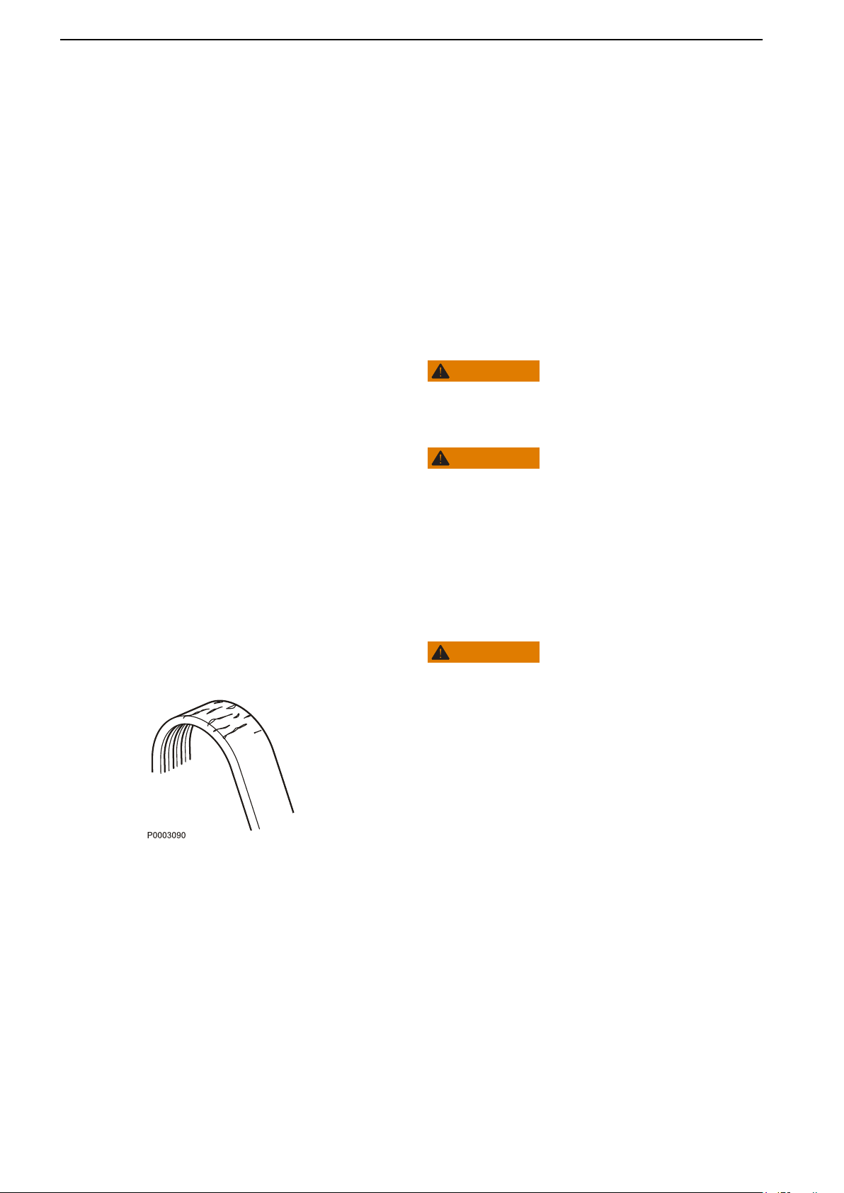
Maintenance
Engine, General
General inspection
Make a habit of visually checking the engine and
engine bay before starting, and after operations when
you have stopped the engine. This will help you to
quickly
to happen.
Look especially carefully for oil, fuel and coolant
leakages, loose bolts, worn or poorly-tensioned drive
belts, loose cable connections, damaged electrical
cables and hoses. This inspection only takes a few
minutes and can prevent serious malfunctions and
expensive repairs.
Accumulations
in the engine room constitute a fire hazard and must
be removed as soon as they are detected.
discover abnormalities, or if something is about
WARNING!
of fuel, oil and grease on the engine or
WARNING!
If
an oil, fuel or coolant leak is detected, the cause must
be investigated and the fault rectified before the engine
is started.
Never direct the jet from a high-pressure washer at
seals, rubber hoses or electrical components. Never
use the high pressure setting for engine cleaning.
Drive Belt, Check and Change
WARNING!
Stop the engine before doing any maintenance work.
General
Check
is tensioned too tightly may damage bearings, while a
belt too-loosely tensioned may slip.
Check and adjust the belt after operation, while the belt
is still warm.
belt tensions and condition regularly. A belt that
92 47708085 11-2016 © Bukh
Page 92
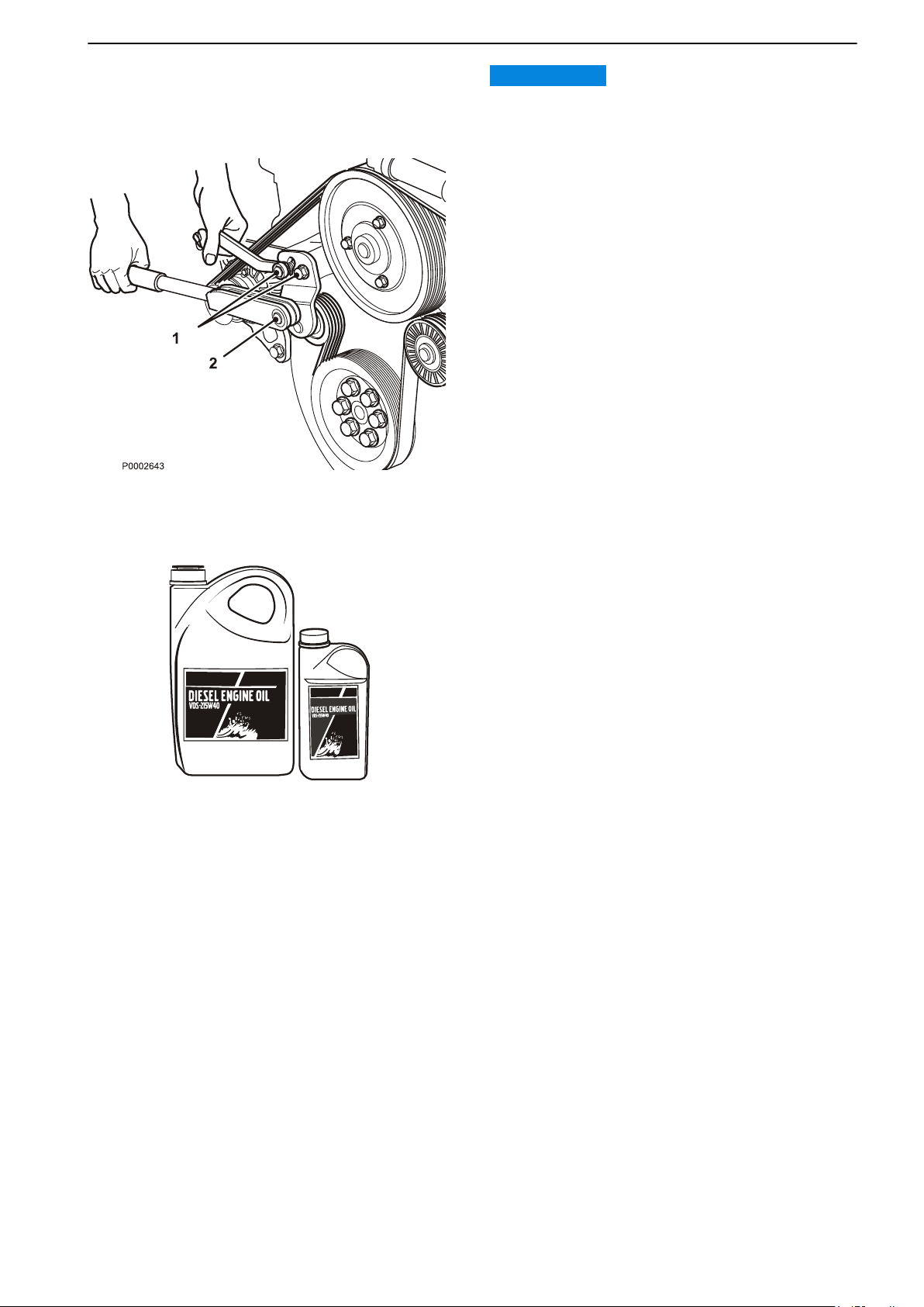
P0002089
Maintenance
IMPORTANT:
Always change a belt which looks worn or cracked.
Adjusting/replacement of drive belts
standard alternator and water pump are driven by
The
a poly-V belt for the best function and lifespan.
Replace/tension the belt as follows:
1 Loosen the screws (1) on the tension roller bracket.
Remove and replace the belt as required.
2 Tension the belt by applying a torque to the
tensioning roller square fitting (2) of 70 Nm (52
lbf.ft). Lock the tensioning roller using screws (1).
The screws must be tightened to 50 Nm (37 lbf.ft).
3 Repeat the procedure when the engine is warm:
Loosen screws (1) and tension the belt.
Lubrication System
Oil change intervals can vary depending on oil grade
and sulphur content of the fuel, please refer to
Technical Data, page 129.
Oil change intervals must never exceed a period of 12
months.
If you want longer oil change intervals than stated in
the table Technical Data, page 129, the condition of
the oil must be checked by the oil manufacturers
through regular oil testing.
47708085 11-2016 © Bukh 93
Page 93

MIN
MAX
P0003706
Maintenance
Oil level, checking and topping up
oil level must be within the marked area on the oil
The
dipstick and must be checked daily before the first
start.
The oil in the engine needs some time to return to the
sump before a correct oil level check can be
performed.
Wait 15 minutes if the engine has been run at normal
operating temperature. Wait an hour if the engine has
been idling.
The oil level shall be between the MAX and MIN marks
on the dipstick. Levels that are higher or lower than
these marks can damage the engine.
IMPORTANT:
Do
not fill up above the maximum oil level. Only use a
recommended grade of oil.
See Technical Data, page 129 for information about
oil level and oil grade.
1 Fill the oil slowly via the filling hole on the top of the
engine.
2 Wait 5 minutes to allow the oil time to reach the
sump before checking the level again.
3 Then check the level again.
94 47708085 11-2016 © Bukh
Page 94

Maintenance
Fuel System
Only use the grades of fuel recommended in the fuel
specification, refer to Technical Data, page 130.
Always observe the greatest cleanliness during
refueling and work on the fuel system.
All work on the unit injectors of the engine must be
carried out by an authorized Bukh workshop.
WARNING!
Fire hazard.
A fuel
spill onto a hot surface or electrical components
can cause fire.
When carrying out work on the fuel system, make sure
the engine is cold.
WARNING!
Store fuel soaked rags and other flammable material
so that there is no danger of them catching fire. Fuel
soaked rags can ignite spontaneously under certain
conditions.
47708085 11-2016 © Bukh 95
Page 95
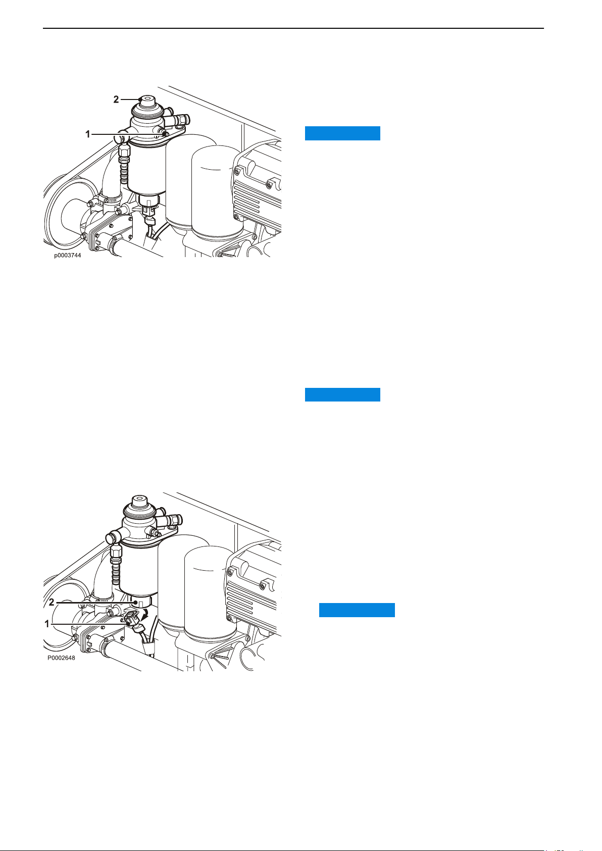
Maintenance
Fuel system, bleeding
The fuel system must be bled after a filter change, if
the fuel tank has been run dry and after a long-term
stoppage.
IMPORTANT:
Never disconnect the pressure pipe.
1 Connect
Feed the hose to a container to avoid spillage.
2 Open the bleeding nipple and pump fuel with the
hand pump (2) until the fuel is free from bubbles.
Close and tighten the bleed nipple.
3 Pump a further 10 times on the hand pump.
Resistance in the hand pump can feel heavy, but
this is completely normal and necessary to bleed
the system.
4 Remove the hose and fit the protective cap to the
bleed nipple.
a transparent hose to the bleed nipple (1).
Water in Fuel
If the EVC system warns for too much water in the fuel
filter, the water separator needs emptying.
IMPORTANT:
Do not continue operating if there is water in the water
separator, it can damage the engine.
Draining the fuel filter
1
Stop the engine and turn off the ignition.
2 Remove the connector piece (1) from the
sensor(2).
3 Place a container under the fuel filter and carefully
unscrew the sensor (2). Let the water run out. When
diesel runs out, screw in the sensor until you feel
slight resistance. Then tighten an additional 1/4 to
1/2 turn.
IMPORTANT:
If the sensor is torqued more than 1/2 turn, the
sensor can be damaged.
4
Refit the connecting piece (1).
96 47708085 11-2016 © Bukh
Page 96
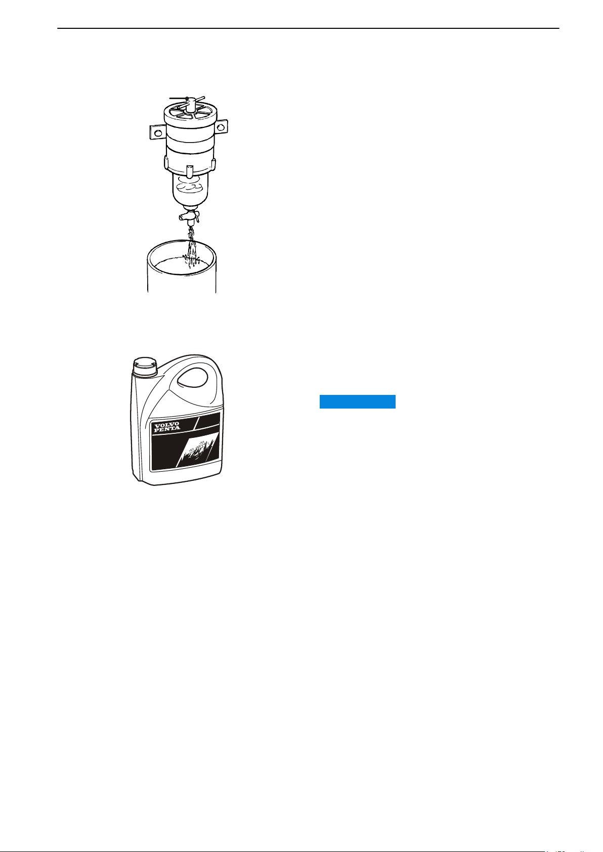
1
P0003060
coolant vcs ready mixed
P0013077
Maintenance
Draining the fuel pre-filter (extra
equipment)
1
Place a container beneath the fuel filter.
Open the bleed screw (1) on the fuel filter about 4
2
turns.
3 Drain the water and contaminants via the plug in the
bottom of the filter.
4 Bleed the fuel system.
Freshwater System
The cooling system ensures that the engine operates
at the correct temperature. It is a closed system that
should always be filled with a coolant mixture.
IMPORTANT:
Coolant of a suitable chemical composition must be
used all year round to protect the engine against
internal corrosion, cavitation and frost bursting.
This even applies when there is no risk for frost
damage, to make sure the engine always has a
complete corrosion protection.
Therefore, the use of anti-corrosion agents alone, or
water alone as a coolant, is not permitted in Bukh
engines.
The coolant must be based on Organic Acid
Technology (OAT). Using an improper coolant or
mixing with another coolant will rapidly reduce the
performance and lifetime of the engine. Material
incompatibility can lead to leakages, which - in the
worst case - can cause engine breakdown.
Bukh strongly recommend the use of our own
coolants, ”Bukh Coolant VCS Ready Mixed” or the
concentrate ”Bukh Coolant VCS”, which ensure the
protection of the cooling system components from
corrosion, ageing, swelling and cracking, thereby
ensuring optimal engine lifetime.
Over time the corrosion protection additives become
less effective, and consequently the coolant must be
changed at regular intervals to maintain sufficient
protection of the engine. The latest Service Protocol
that specifies service intervals can be found at
volvopenta.com.
47708085 11-2016 © Bukh 97
Page 97
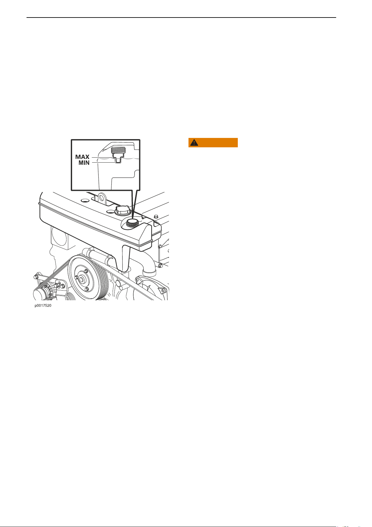
Maintenance
Coolant, Mixing
It is extremely important that the system is filled with
the correct coolant concentration; refer to Technical
Data, page 132.
The coolant should be mixed with distilled, deionized
water. For Bukh specified water requirements; refer
to Technical Data, page 132.
NOTICE! If water quality can not be guaranteed, use
ready mixed coolant.
Coolant Level, Checking and
Topping Up
WARNING!
Do not open the coolant filler cap when the engine is
hot, except
personal injury. Steam or hot fluid could spray out.
1 Turn the filler cover slowly counter-clockwise and
release any pressure from the system before
removing the cover completely.
in emergencies as this could cause serious
2 Top the coolant up as necessary. The coolant level
shall be between the MAX and MIN marks on the
expansion tank.
3 Screw the filler cover on.
Seawater System
The raw water system is the engine's external cooling
system. On engines with drives, the raw water pump
sucks in water via the drive, through the control
system's oil cooler to the raw water pump. The water
then passes through the raw water filter before being
pumped through the fuel cooler, intercooler, engine oil
cooler and heat exchanger. Finally the water is fed out
through the exhaust elbow, where it is mixed with the
exhaust gases.
On engines with reverse gears, the raw water pump
sucks in water via a raw water intake, after which the
water passes a raw water filter (extra equipment)
before being pumped through the intercooler, heat
exchanger, engine oil cooler and gearbox oil cooler.
Finally the water is fed out through the exhaust elbow,
where it is mixed with the exhaust gases.
98 47708085 11-2016 © Bukh
Page 98
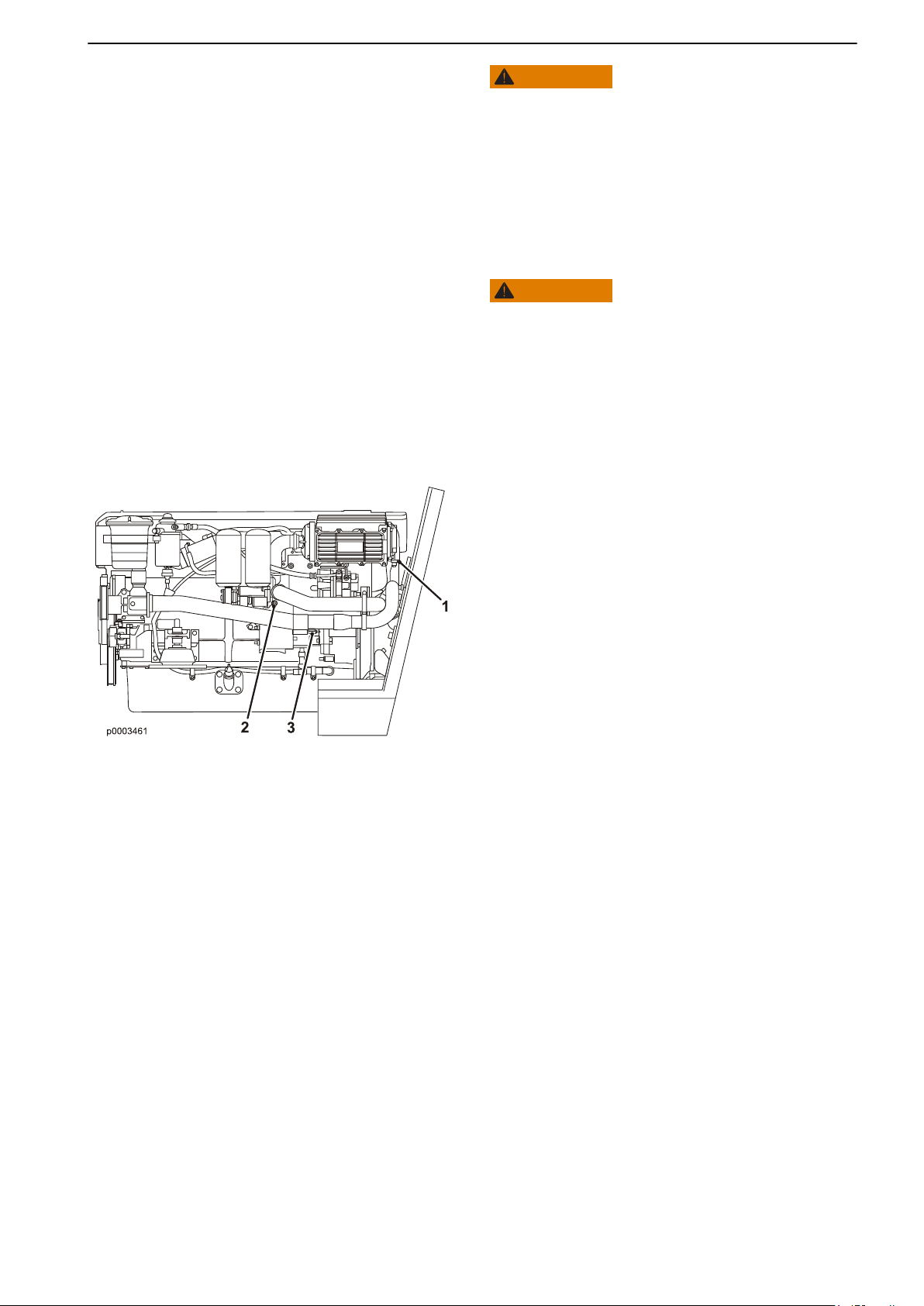
Maintenance
WARNING!
Risk of water entry. Water will flow into the boat if any
hose,
plug etc. located below the waterline is removed
when the boat is in the water. Always close the sea
cocks. If the boat does not have sea cocks the water
flow must be blocked in a safe manner. If this is not
possible, the boat must be drawn up on land before
work starts.
Seawater System, Draining
WARNING!
Risk of water entry. Close the seawater cocks before
doing any work on the seawater system.
To prevent frost damage, the raw water system must
drained during cold weather if there is a risk for frost.
be
An alternative to draining is to keep the engine room
warm using an approved heater fan.
Draining:
1 Close the sea cock where fitted.
2 Open the drain stop cock (1) by unscrewing it
carefully.
3 Drain the coolant into a container. Screw in the stop
cock by hand.
4 Move the hose on the stop cock (1) and connect to
stop cock (2).
Open stop cock (2) and drain all coolant. Close the
stop cock.
5 Move the hose to stop cock (3).
Open stop cock (3) and drain all coolant. Close the
stop cock.
6 Refit the drain hose to stop cock (1).
7 Open the sea cock where fitted.
47708085 11-2016 © Bukh 99
Page 99
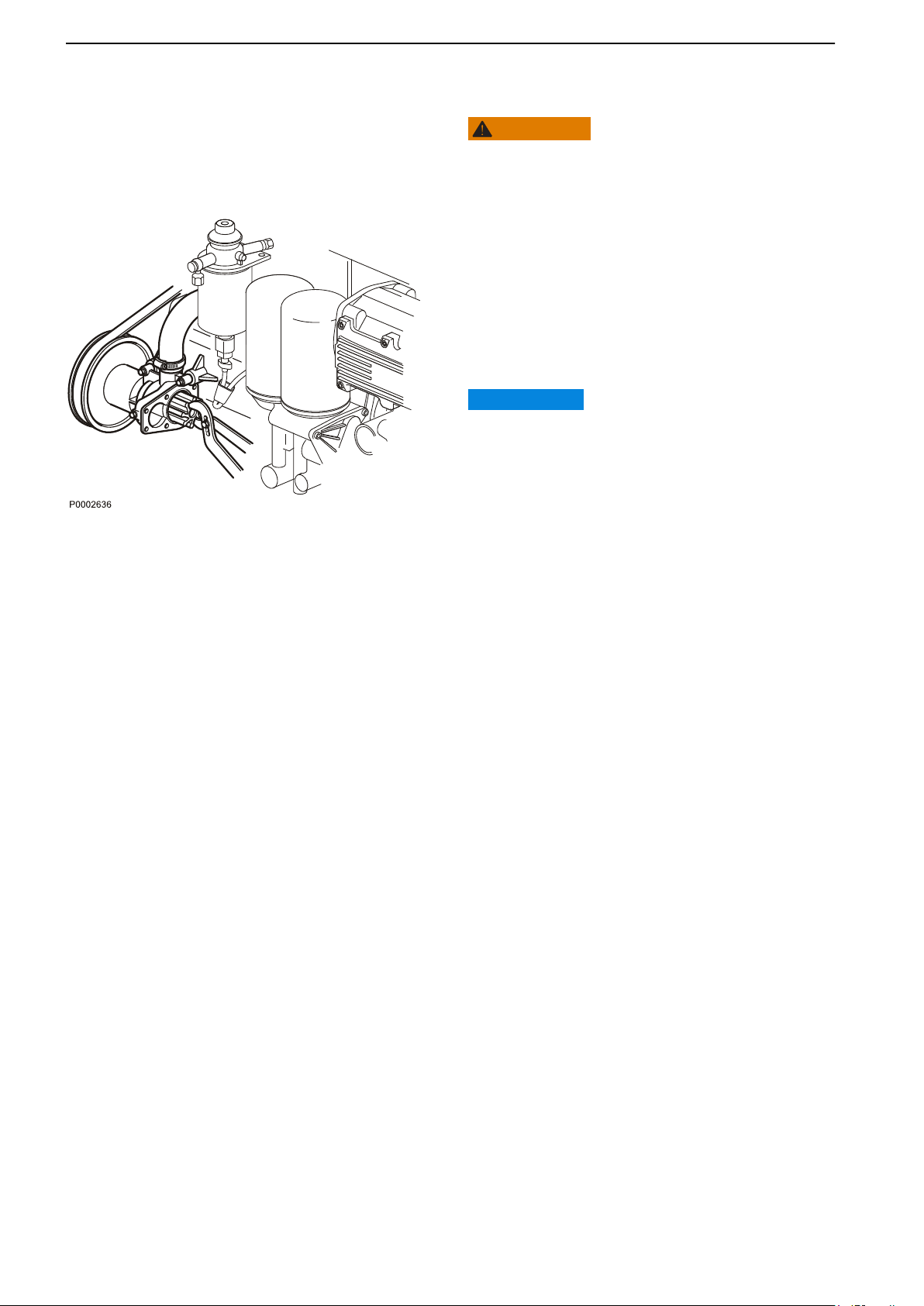
Maintenance
Impeller, Check and Change
WARNING!
Risk of water entry. Close the seawater cocks before
doing any work on the seawater system.
1
Remove the cover from the raw water pump and
remove the impeller.
If the impeller is cracked or damaged it must be
replaced.
2 If the pump shaft can be turned by hand, the flange
must be replaced.
3 Lubricate the pump housing and inside of the cover
with a little glycerin.
IMPORTANT:
The impeller may get damaged if other types of
lubricant than glycerin are used.
4 Press
5 Fit the sealing washer on the center bearing of the
the impeller in with an anti-clockwise rotating
movement.
shaft. Install the cover with a new O-ring.
Seawater System, Cleaning and
Inhibiting
The raw water system must be flushed with fresh
water, to prevent deposits and salt crystals from
building up inside it. It must also be conserved when
the boat is laid up for winter/out of season storage so
that it is protected from internal corrosion.
100 47708085 11-2016 © Bukh
Page 100
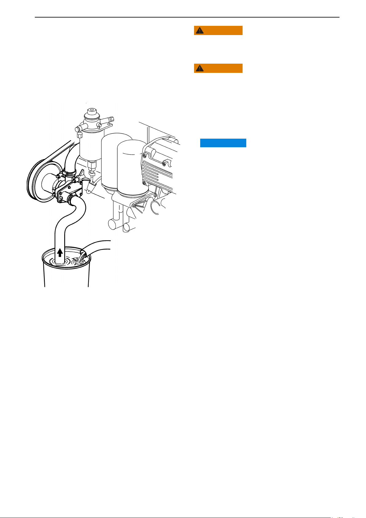
Maintenance
WARNING!
Risk of water entry.
Cleaning
carried out with the boat on land.
and inhibiting the seawater system should be
WARNING!
Working with or approaching a running engine is a
safety
risk. Watch out for rotating components and hot
surfaces.
boats with reverse gears, open the sea cock.
1 On
2 Disconnect the hose from the raw water pump
and install a hose which goes to a bucket filled
with fresh water. Arrange re-filling.
IMPORTANT:
The impeller could be damaged if the pump runs
dry.
3 Check
4 Set the control lever to neutral and start the
5 Fill a bucket with a mixture of 40% glycol and
6 Start the engine and let it idle. Stop the engine
7 Put the raw water hose back.
8 The system has now been conserved. The
that there is no one near the propeller and
no one will be splashed by the exhaust outlet.
engine. Let it run at fast idle for a few minutes.
Stop the engine.
60% fresh water, to conserve the system. Fix a
container at the exhaust outlet.
just before the mixture is used up. Repeat until
the entire system has been flushed with the
mixture.
glycol mixture should remain in the system
during storage.
Before launching the boat, drain the mixture and
hand it to a re-cycling station for disposal
47708085 11-2016 © Bukh 101
 Loading...