

Buhler CSPB1 series Installation And Operation Instructions Manual
Analysentechnik
Installation and Operation Instructions
Original instructions
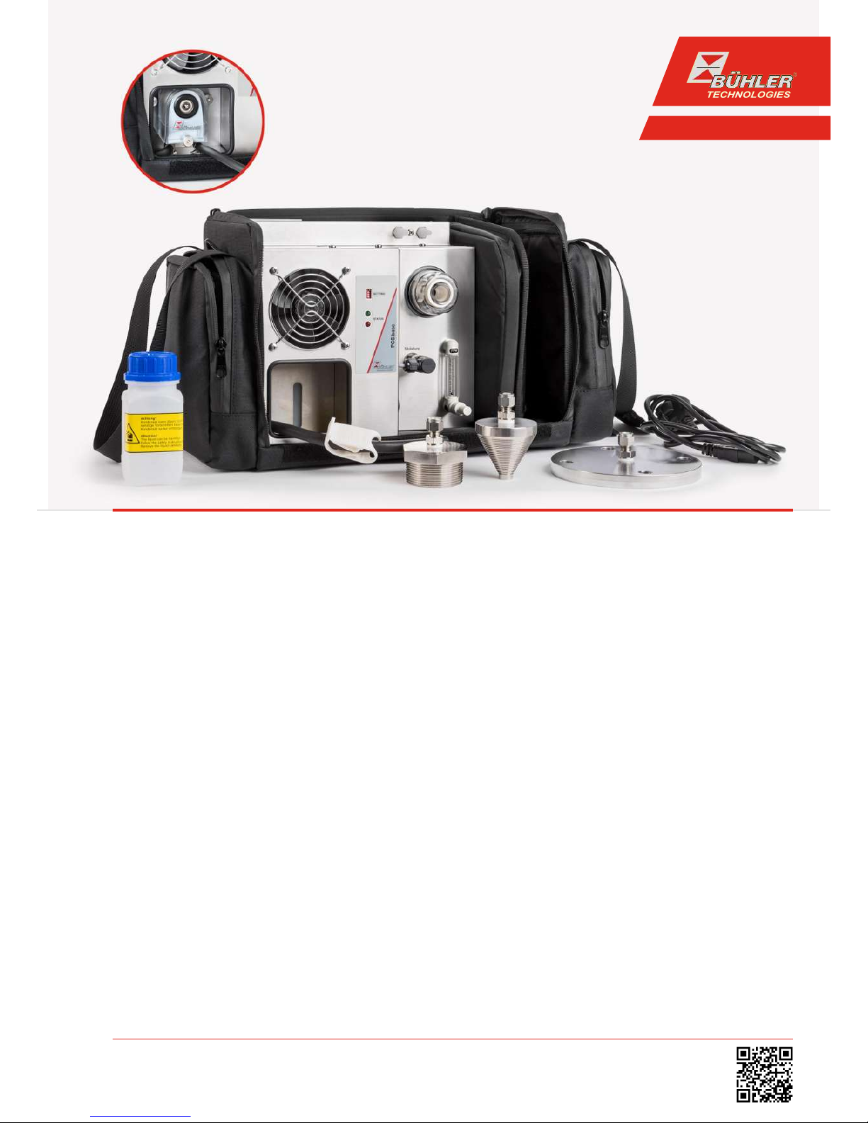
Portable sample gas conditioning
PCS.base
BE464003
11/2017
Bühler Technologies GmbH, Harkortstr. 29, D-40880 Ratingen
Tel. +49 (0) 21 02 / 49 89-0, Fax: +49 (0) 21 02 / 49 89-20
E-Mail: analyse@buehler-technologies.com
Internet: www.buehler-technologies.com

Bühler Technologies GmbH, Harkortstr. 29, D-40880 Ratingen
Tel. +49 (0) 21 02 / 49 89-0, Fax: +49 (0) 21 02 / 49 89-20
Internet: www.buehler-technologies.com
E-Mail: analyse@buehler-technologies.com
Read this instruction carefully prior to installation and/or use. Pay attention particularly to all advises and safety instructions to prevent injuries. Bühler Technologies can not be held responsible for misusing
the product or unreliable function due to unauthorised modifications.
All rights reserved. Bühler Technologies GmbH 2017
Document information
Document No......................................................... BE464003
Version........................................................................... 11/2017

PCS.base
Contents
1 Introduction..................................................................................................................................................................................................................... 2
1.1 Intended Use......................................................................................................................................................................................................... 2
1.2 Ordering instructions ........................................................................................................................................................................................ 2
1.3 Contents................................................................................................................................................................................................................. 2
1.4 Product description ............................................................................................................................................................................................ 2
2 Safety instructions......................................................................................................................................................................................................... 3
2.1 Important advice ................................................................................................................................................................................................. 3
2.2 General hazard warnings .................................................................................................................................................................................4
3 Transport and storage .................................................................................................................................................................................................. 5
4 Setup and connection................................................................................................................................................................................................... 6
4.1 Installation site requirements.........................................................................................................................................................................6
4.2 Connecting a gas probe.....................................................................................................................................................................................6
4.3 Electrical connections ........................................................................................................................................................................................6
4.4 Delta-T Control..................................................................................................................................................................................................... 7
4.5 DIP switch settings .............................................................................................................................................................................................. 8
5 Operation and control ..................................................................................................................................................................................................9
5.1 Switching on the PCS.base................................................................................................................................................................................ 9
5.2 Operating the sample gas pump.................................................................................................................................................................... 9
5.3 Operating the flow metre (optional) ...........................................................................................................................................................10
5.4 Condensate ......................................................................................................................................................................................................... 10
5.4.1 Version with condensate trap ........................................................................................................................................................10
5.4.2 Version with condensate pump .....................................................................................................................................................10
6 Maintenance...................................................................................................................................................................................................................11
6.1 Replacing the filter element............................................................................................................................................................................ 11
7 Service and repair..........................................................................................................................................................................................................12
7.1 Troubleshooting ................................................................................................................................................................................................ 12
7.2 Safety instructions .............................................................................................................................................................................................13
7.3 Replacing the main fuse...................................................................................................................................................................................13
7.4 Replacing the fuse of the cooler .................................................................................................................................................................... 14
7.5 Drying of the moisture detector (option) ....................................................................................................................................................15
7.6 Cleaning and removal of the heat exchanger............................................................................................................................................15
7.7 Replacing the hoses of the peristaltic pump (option).............................................................................................................................15
7.8 Spare parts and accessories ............................................................................................................................................................................15
7.8.1 Spare parts and accessories............................................................................................................................................................. 16
8 Disposal............................................................................................................................................................................................................................17
9 Appendices..................................................................................................................................................................................................................... 18
9.1 Technical Data ....................................................................................................................................................................................................18
9.2 Flow chart ............................................................................................................................................................................................................ 18
10 Attached documents................................................................................................................................................................................................... 19
iBühler Technologies GmbHBE464003 ◦ 11/2017
PCS.base
1 Introduction
1.1 Intended Use
The respective operating conditions greatly impact an analysis instrument working correctly. Since in addition to the gas component to be analysed, sample gas often contains large amounts of moisture and dirt particles, the sample gas must be conditioned accordingly. Especially with frequently changing sampling points this often causes problems. Accurate gas analyses in
changing locations require compact gas conditioning systems. PCS.base was developed for these applications.
DANGER Potentially explosive atmosphere
Explosion hazard if used in hazardous areas.
The device is not suitable for operation in hazardous areas with potentially explosive atmospheres.
Do not expose the device to combustible or explosive gas mixtures.
1.2 Ordering instructions
The item number is a code for the configuration of your unit. Please use the following model key:
CSPB1 X X X 0 0 Product Characteristics
Moisture detector
0 No
1 Yes
Flow meter
0 No
1 Yes
Condensate drain
0 Condensate trap*
1 Condensate pump 115 V
2 Condensate pump 230 V
*When selecting the condensate trap the system can be operated at a 110-260V voltage range.
1.3 Contents
– PCS.base in the selected version
– Optional accessories such as sample gas probe, process connectors or flanges
– Product documentation
1.4 Product description
The low weight and small dimensions of the system are ideal for e.g. service engineers using sample- or comparison measurements.
A carrying bag provides reliable protection from the weather and mechanical damage to the product and allows for convenient
system transport.
The base version of the gas condition system consists of a gas cooler with condensate trap, a gas pump and filter. For more accessories and options please refer to the table in the data sheet.
The sample gas is cooled to the preset dew point (factory preset 5 °C) regardless of the ambient temperature. This safely falls below the dew point and moisture in the sample gas is separated as condensate. A safety circuit only starts the gas pump once the
operating point of the cooler has been reached. The optional moisture detector communicates with the sample gas pump,
switching it off in the event of water burst or cooler overload.
2 Bühler Technologies GmbH BE464003 ◦ 11/2017
PCS.base
2 Safety instructions
2.1 Important advice
Operation of the device is only valid if:
– the product is used under the conditions described in the installation- and operation instruction, the intended application
according to the type plate and the intended use. In case of unauthorized modifications done by the user Bühler Technologies GmbH can not be held responsible for any damage,
– when complying with the specifications and markings on the nameplates.
– the performance limits given in the datasheets and in the installation- and operation instruction are obeyed,
– monitoring devices and safety devices are installed properly,
– service and repair is carried out by Bühler Technologies GmbH,
– only original spare parts are used.
This manual is part of the equipment. The manufacturer keeps the right to modify specifications without advanced notice. Keep
this manual for later use.
Signal words for warnings
DANGER
Signal word for an imminent danger with high risk, resulting in severe injuries or death if not avoided.
WARNING
Signal word for a hazardous situation with medium risk, possibly resulting in severe injuries or death if not
avoided.
CAUTION
Signal word for a hazardous situation with low risk, resulting in damaged to the device or the property or
minor or medium injuries if not avoided.
NOTICE
Signal word for important information to the product.
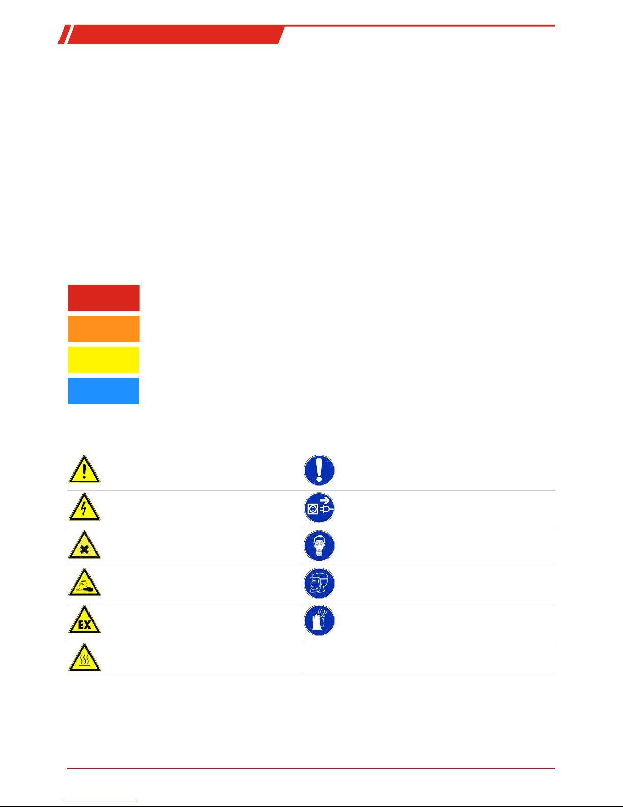
Warning signs
In this manual, the following warning signs are used:
Warning against hazardous situations General notice
Warning against electrical voltage Disconnect from mains
Warning against respiration of toxic gases Wear respirator
Warning against acid and corrosive substances Wear eye/face protection
Warning against potentially explosive atmospheres Wear protection gloves
Warning against hot surface
3Bühler Technologies GmbHBE464003 ◦ 11/2017
PCS.base
2.2 General hazard warnings
The equipment must be installed by a professional familiar with the safety requirements and risks.
Be sure to observe the safety regulations and generally applicable rules of technology relevant for the installation site. Prevent
malfunctions and avoid personal injuries and property damage.
The operator of the system must ensure:
– Safety notices and operating instructions are available and observed,
– The respective national accident prevention regulations are observed,
– The permissible data and operational conditions are maintained,
– Safety guards are used and mandatory maintenance is performed,
– Legal regulations are observed during disposal.
Maintenance, Repair
Please note during maintenance and repairs:
– Repairs to the unit must be performed by Bühler authorised personnel.
– Only perform conversion-, maintenance or installation work described in these operating and installation instructions.
– Always use genuine spare parts.
Always observe the applicable safety and operating regulations in the respective country of use when performing any type of
maintenance.
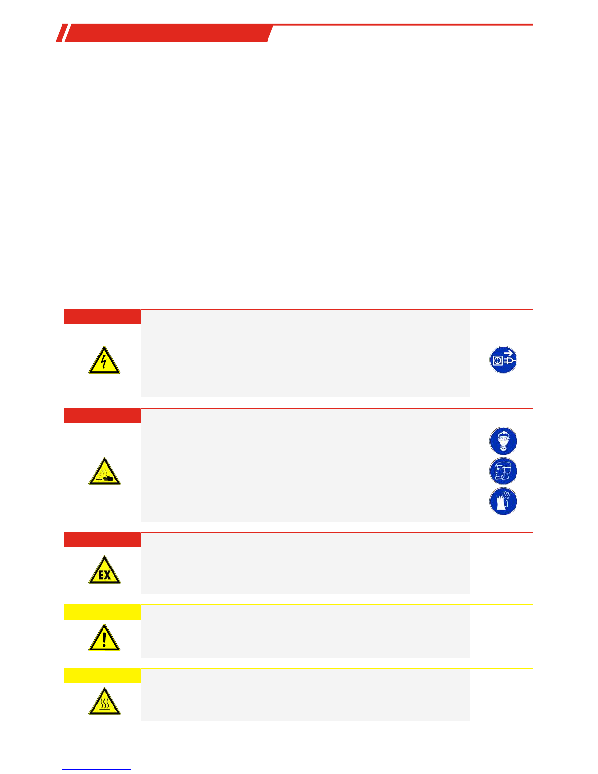
DANGER Electrical voltage
Electrocution hazard.
a) Disconnect the device from power supply.
b) Make sure that the equipment cannot be reconnected to mains unintentionally.
c) The device must be opened by trained staff only.
d) Regard correct mains voltage.
DANGER Toxic, corrosive gas/condensate
Sample gas/condensate may be hazardous to health.
a) If necessary, ensure a safe gas/condensate discharge.
b) Always disconnect the gas supply when performing maintenance or repairs.
c) Protect yourself from toxic/corrosive gasses/condensate when performing mainten-
ance. Wear appropriate protective equipment.
DANGER Potentially explosive atmosphere
Explosion hazard if used in hazardous areas.
The device is not suitable for operation in hazardous areas with potentially explosive atmospheres.
Do not expose the device to combustible or explosive gas mixtures.
CAUTION Tilting risk
Damage of the device
Secure the device against any sudden translocation during maintenance.
CAUTION Hot surface
Burning hazard
Let the device cool down before maintaining.
4 Bühler Technologies GmbH BE464003 ◦ 11/2017
PCS.base
3 Transport and storage
The device must always be stored and transported in the original transport bag. Operation without transport bag is prohibited.
Only transport the device in the designated position (upright, level). If this cannot be ensured due to logistics (e.g. transport via
shippers or air transport), it’s important to completely empty the condensate trap (versions without condensate trap), as condensate could otherwise flow back into the gas lines. Purge the gas path with preferably dry ambient air to allow acidic condensate to escape. Proceed as described in chapter Condensate [> page10].
DANGER Toxic, corrosive condensate
a) Protect yourself from toxic, corrosive condensate when performing any type of work.
b) Wear appropriate protective equipment.
c) Please note the national safety rules!
The equipment must be protected from moisture and heat when not in use. It must be stored in a covered, dry and dust-free
room at a temperature between -20 °C and 40 °C.
Outdoor storage is
prohibited
. On principle the operator must meet all applicable standards with respect to preventing damage
due to lightning, which could result in sample gas pump damage.
Storage areas must not contain any equipment generating ozone, e.g. fluorescent lighting, mercury vapour lamps, high voltage
electrical equipment.
5Bühler Technologies GmbHBE464003 ◦ 11/2017
PCS.base
4 Setup and connection
Check the device for damage prior to installation. This/these could be a damaged housing or add-on components visible from
the outside, such as filter and flow meter. Never use equipment with obvious damage.
CAUTION Damage/health hazard due to heater leakage
Check the device for obvious leaks before every use and at regular intervals. Any leaks
must be repaired prior to using the device. In addition to gas leaks, leaking fluids in particular can post an electrical and health hazard.
4.1 Installation site requirements
Be sure the equipment is located on a level, solid surface. Also be sure to comply with the approved ambient temperature.
Do not obstruct the convection of the cooler. There must be adequate room between the vent and the next obstacle (at least 10
cm).
CAUTION Damage to the device
Protect the equipment against dust, falling objects and external impacts.
Stroke of lightning
Outdoor installation is
forbidden
. As a matter of principle, the operator must regard all
applicable standards according prevention of damage due to lightning, which may otherwise damage the device.
4.2 Connecting a gas probe
The sample gas probe connects to the DN 6 hose connection on the device marked IN.
The following devices (e.g. analyser) must be connected to the DN 4 hose connection marked
OUT
with a suitable hose.
4.3 Electrical connections
WARNING Hazardous electrical voltage
The device must be installed by trained staff only.
CAUTION Wrong mains voltage
Wrong mains voltage may damage the device.
Regard the correct mains voltage as given on the type plate.
The low heat device socket features an on/off switch which cuts off all poles. This must be set to the zero position prior to connecting the electrical.
Connect the included low heat device cable to the device and a suitable voltage source. Please note the correct voltage and frequency. The type plate contains any deviating specifications.
PCS.base with condensate trap may be operated on 110-260VAC, 50/60Hz voltage. When using the condensate pump the
voltage is 115V, 60Hz or 230V, 50Hz.
6 Bühler Technologies GmbH BE464003 ◦ 11/2017
 Loading...