

Buhler Commercial FK348 Operator And Parts Manual


Commercial Snowblower
TABLE OF CONTENTS
DESCRIPTION PAGE
Warranty......................................................................1
Safety Instructions.......................................................2
Safety Signs & Safety Sign Locations.......................... 3
Operating Instructions..................................................5
Hydraulic Control Block Instructions ............................7
Hydraulic Control Block Parts List & Drawing..............8
Assembly Instructions..................................................9
Hydraulic Snowblower – 22” Housing Drawings ..........12
Hydraulic Snowblower – 22” Housing Parts List ..........14
Hydraulic Snowblower – 24” Housing Drawings ..........17
Hydraulic Snowblower – 24” Housing Parts List ..........19
Hydraulic Snowblower – Assembly Drawing................21
Hydraulic Snowblower – Assembly Parts List..............22
PTO Snowblower – 24” Housing Drawings..................23
PTO Snowblower – 24” Housing Parts List..................25
PTO Drawing & Parts List............................................27
Cylinder Assembly Drawing & Parts List......................28
Gearbox Drawing & Parts List......................................29
Specifications...............................................................30
Hydraulic Snowblower Schematic ................................ 31
Troubleshooting........................................................... 32
Shipping Bundles.........................................................33

Commercial Snowblower
WARRANTY POLICY
Buhler Manufacturing products are warranted for a period of twelve (12) months (90 days for
commercial application) from original date of purchase, by original purchaser, to be free from
defects in material and workmanship under correct, normal agricultural use and proper
applications.
Buhler Manufacturing’s obligations under this warranty shall be limited to the repair or
exchange, at Buhler Manufacturing’s option, of any Buhler Manufacturing product or part which
proves to be defective as provided. Buhler Manufacturing reserves the right to either inspect
the product at the buyer’s location or have it returned to the factory for inspection.
The above warranty does not extend to goods damaged or subject to accident, abuse or misuse
after shipment from Buhler Manufacturing’s factory, nor to goods altered or repaired by anyone
other than an authorized Buhler Manufacturing representative.
Buhler Manufacturing makes no Express Warranties other than those, which are specifically
described. Any description of goods, including any references and specifications in catalogues,
circulars and other written material published, is for the sole purpose of identifying goods and
shall conform to such descriptions. Any sample or model is for illustrative purposes only and
does not create an Express Warranty that the goods conform to sample or model shown.
The purchaser is solely responsible for determining suitability of goods sold. This warranty is
expressly in lieu of all other warranties expressed or implied. Buhler Manufacturing will in no
event be liable for any incidental or consequential damages whatsoever. Nor for any sum in
excess of the price received for the goods for which liability is claimed.
WARRANTY CLAIMS:
Warranty requests must be prepared on Buhler Manufacturing Warranty Claim Forms with all
requested information properly completed. Warranty Claims must be submitted within a thirty
(30) day period from date of failure repair.
WARRANTY LABOR:
Any labor subject to warranty must be authorized by Buhler Manufacturing. The labor rate for
replacing defective parts, where applicable, will be credited at 100% of the dealer’s posted shop
rate. Defective parts will receive an extra 10% discount to assist with freight or other incidental
costs.
GOVERNMENT LEGISLATION:
Warranty terms and conditions are subject to Provincial or State legislation.
IMPORTANT FACTS:
Buckets and Bucket Tines Carry No Warranty
Bent Spears Carry No Warranty
Snowblower Fan Shafts Carry No Warranty
Mower Blades Carry No Warranty
Portable Auger Parts Have Two (2) Year Warranty
Loader Parts Have Two (2) Year Warranty
IMPORTANT NOTE: This warranty does not apply to rentals
1

Commercial Snowblower
SAFETY INSTRUCTIONS
CAUTION
1. Always review operator’s manual before starting new machine.
2. Do not let inexperienced operators or children run this equipment.
3. Never service or clean unit while it is running.
4. Do not remove shields.
5. Stay clear of augers.
6. Stay clear of discharge chute. Rocks can be picked up and thrown.
7. Do not operate in the fully raised position.
8. Relieve pressure on hydraulic system before repairing or adjusting.
9. Wear hand and eye protection when looking for hydraulic leaks. Use
cardboard to look for leaks.
10. The quick tach must be securely locked in place before using snowblower.
11. Poor judgment results in accidents. Always be careful.
12. Remember a careful operator is the best insurance.
THIS SYMBOL MEANS
STAY ALERT! WATCH FOR IT!
2
Commercial Snowblower
SNOWBLOWERS
This manual is for both Commercial Hydraulic Snowblowers and Commercial PTO
Drive Snowblowers. The hydraulic models come in 60”, 66”, 74” and 84” widths. The
PTO drive model is only available in an 84” width. Hydraulic models come with four
different motor series. Hydraulic output on the equipment running the Snowblower must
match the requirement for each motor series for the Snowblower to work. The hitch is a
skid steer fixed type of quick hitch. The PTO drive model runs at 540 rpm. It is
supplied with category 2 hitch pins. There is a shear bolt on the auger and two on the
PTO
shaft to protect the machine from damage if a large object is picked up. All
Snowblowers come with a hydraulic chute control as standard.
Hydraulic Drive
PTO Drive
3
Commercial Snowblower
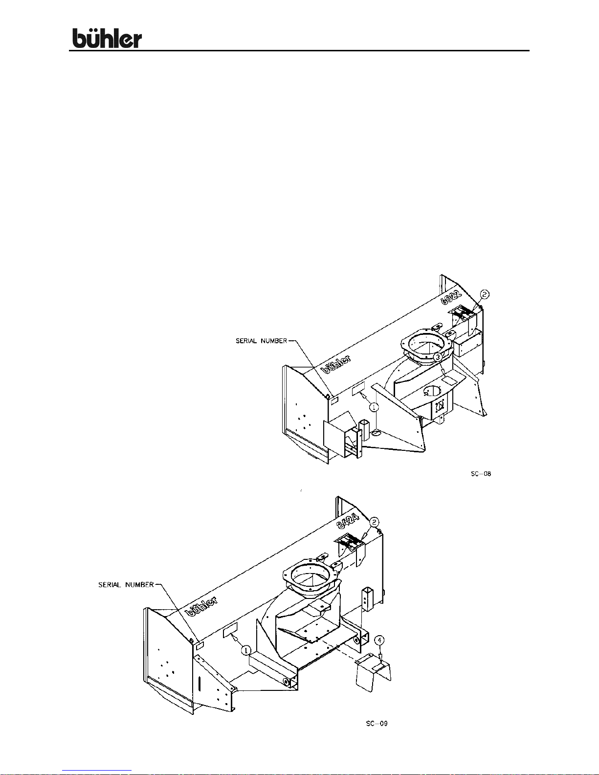
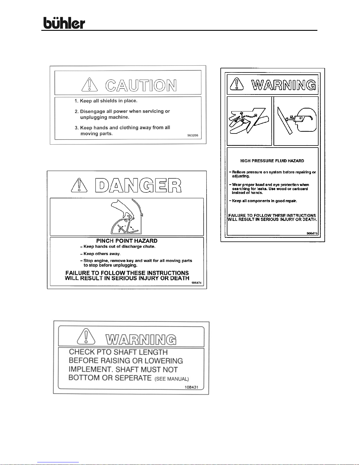
SAFETY SIGNS
#1
#3
#4
4
#3
Replace safety signs
immediately should they
become damaged, torn or
illegible. Obtain replacements
from your authorized dealer
using the part numbers shown.

Commercial Snowblower
OPERATING INSTRUCTIONS
1. HYDRAULIC DRIVE: All snowblower hydraulic blocks are set at the factory
for a 2800 - 3000 psi system. Refer to the section on the hydraulic control
block if your system does not fall into this range.
2. ALL: Depth of the cut can be partially controlled by tilting the snowblower
forward or backward.
3. PTO DRIVE: Adjust the top link of the tractor hitch so the snowblower is just
slightly tilted back when resting on the ground. CAUTION: Excessive
backward tilt may cause the “U” joints to flutter resulting in PTO shear bolt
failure.
4. PTO DRIVE: The inside holes on the hitch are spaced to fit a category 2
quick hitch using the pins supplied. The hitch will also fit category 2 three
point arms or category 3 if you add bushings.
5. PTO DRIVE: Adjust the lower link sway chains or blocks on the tractor to
restrict movement of the blower when operating.
6. ALL: All snowblowers have a hydraulic control spout and spout deflector.
Refer to the hydraulic control block section. The pressure to the chute control
is regulated by the two torque limit controls (#13b and #13c). Each controls
the hydraulic pressure in one direction. They are set at the factory to about
2 ½ turns. If the pressure is too low, the chute won’t turn. If the pressure is
too high you could damage the teeth on the spout control ring. To adjust the
pressure, you loosen the lock nut on the modulating valve and back off the
adjusting screw till the screw turns freely by hand. Turn the screw in till you
feel it making contact and turn in 2 ½ turns. Start with this setting to do any
fine adjustment if necessary. Pressure should not go over 1000 psi.
The deflector cylinder pressure is regulated by no-load control (#13a).
It is set at the factory to about 2 turns. If pressure is too low it will not
operate. Excess heat will be generated if it is set too high. Adjust if
necessary as per previous paragraph. Operating pressure should be about
700 psi.
7. ALL: Run the snowblower at low rpm to check operation before blowing
snow.
8. PTO DRIVE: The blower has three shear bolts to protect the tractor and
blower in case a large object enters the blower. PTO shear bolt – two 5/16” x
1” (grade 8); auger shear bolt – 5/16” x 1 ¼” (grade 5). Shear bolts should be
fastened with a lock nut or two jam nuts. These bolts must be tight to prevent
wear of the bolts and bolt holes.
9. PTO DRIVE: Never run PTO at over 600 rpm.
5

Commercial Snowblower
OPERATING INSTRUCTIONS – cont’d.
10. ALL: Chain tension on auger chain should be set at 3/8” to 1/2” slack.
11. LUBRICATION:
a) ALL: The gear teeth on the chute control should be periodically
lubricated with gun grease.
b) PTO DRIVE: PTO shaft universal joints and square shaft slide should
be periodically lubricated with a grease gun.
c) ALL: Regularly oiling the chain will significantly increase the life of the
chain.
d) PTO DRIVE: Use any 80-90 gear oil or multigrade with 80 minimum in
the gearbox up to the level plug height.
12. ALL: Periodically check all bolts for tightness. The bolt holding on the fan
and the bearing bolts are of particular importance.
13. HYDRAULIC DRIVE: Always use goggles and gloves when checking for
hydraulic leaks. Use a piece of cardboard instead of your hands to look for
leaks.
14. ALL: Always shut off snowblower for servicing or unplugging. Disengage
hydraulics or PTO shaft.
15. PTO DRIVE: Check the shear sprocket at the beginning of every season to
make sure it will spin freely. Clean to loosen if necessary.
16. ALL: When replacing bearings or tightening a loose bearing collar, always
tighten collar in the
tool.
17. HYDRAULIC DRIVE: WARNING: The locking pins must extend through
the holes in the attachment when mounting the snowblower to an implement.
Levers must be fully down and locked. Failure to secure pins can allow
attachment to come off and cause injury or death.
6
direction of shaft rotation using a center punch or a similar

Commercial Snowblower
HYDRAULIC CONTROL BLOCK
NON-STALLING-FAN FEATURE:
The Hydraulic Snowblower has a unique modulating element that keeps the blower fan
from stalling in an overloaded condition. This is accomplished by starving the hydraulic
flow to the front auger motor (which then stops feeding the fan) and diverts all of the
flow (and energy) to the main fan motor. As the fan clears itself, and the pressure
drops, the auger again begins feeding according to load. When the system is set up
properly the fan motor should not stall or plug up.
MODULATING ELEMENT SETUP:
For optimum performance the modulating element (#4) (page 8) must be adjusted to
match the system pressure of the tractor being used. The factory setting is for a 28003000 psi system. If your system is less, you should make adjustments accordingly. For
adjustment:
Loosen the LOCK NUT (on the MODULATING VALVE (#4) (page 8) and back off
the adjusting screw till the screw turns freely by hand, and then turn it in till you
feel the screw making contact with the pressure spring. One turn sets the
pressure up by about 600 psi.
For 2100 psi turn the screw in 3 ½ turns.
For 2400 psi, turn in 4 turns
For 2700 psi, turn in 4 ½ turns
For 3000 psi, turn in 5 turns.
If the fan stalls (in an over load condition), the (#4) (page 8) element is set too high. If
the Auger slows and stops too soon, it is set too low. Once it is set it should not need to
be adjusted any more.
Since there are a number of unknown variables that are unique to almost every
situation, it is difficult to give an exact setting for a particular model. The variables are:
hose size and length, type and size of quick couplers, etc.
7
Commercial Snowblower
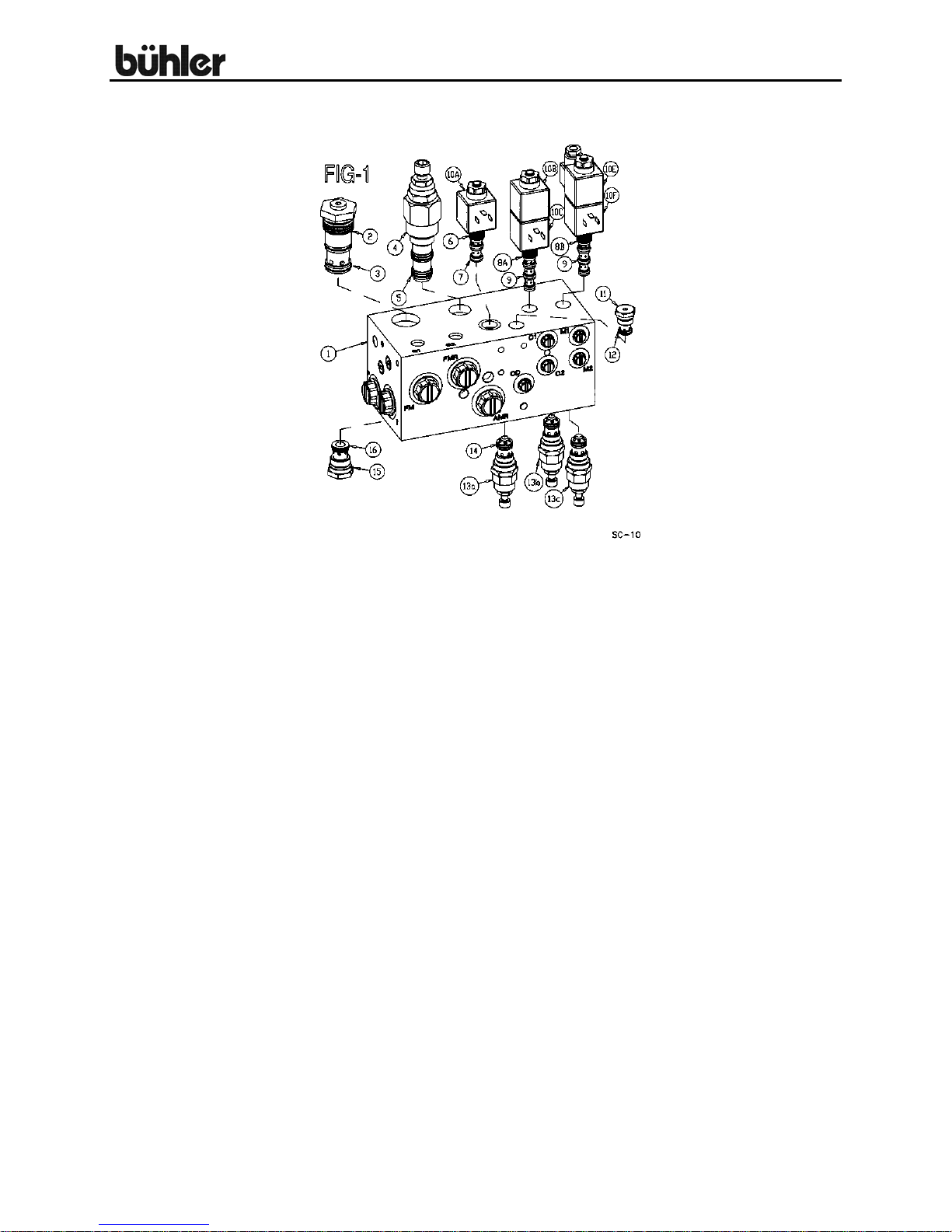
HYDRAULIC CONTROL BLOCK DRAWING AND PARTS LIST
HYD MANIFOLD ASSEMBLY
Item # Part # Description
1 905669 Main Block
2 813922 Logic Element
3 X2732 Element Seal Kit
4 813923 Control Valve
5 X2733 Seal Kit
6 813924 No-Load Valve
7 X2734 Seal Kit
8ab 813925 Chute Cont. Valves
9 X2735 Seal Kit
10a 813926 No-Load Press. Coil
10bc 813926 Chute Up Down Coil
10ef 813926 Chute Left Right Coil
11 813929 Check Valve
12 X2736 Seal Kit
13a 813930 No-Load Control
13bc 813930 Torque Limit Control
14 X2737 Seal Kit
15 813931 Check Valve
16 X2745 Seal Kit
8

Commercial Snowblower
ASSEMBLY INSTRUCTIONS
1. SPOUT ASSEMBLY FOR ALL SNOWBLOWERS: Remove two of the
grooved spout rollers to mount the discharge spout. Replace the two rollers
to hold spout in place. Install the 2 ½” x 8” cylinder on the spout using the
pins supplied.
2. HYDRAULIC DRIVE: (Page 21 & 22) The 80” long hydraulic lines (#14) for
the spout deflector cylinder should be connected to the two ports on the
hydraulic block labeled C1 and C2 (see Page 8 for block drawing). The 30”
long lines (#15) from the spout control motor connect to the two ports labeled
M1 and M2 on the hydraulic block. The ¾” diam. x 84” main
lines (#21) connect to the implement. NOTE: The customer must supply the
appropriate tips to connect the main lines to the implement. A two-piece
wiring harness is supplied with all hydraulic snowblowers. The 45” part of the
harness (#6) is mounted on the snowblower. One end of this wire connects
to the control block. The plug end mounts on a bracket welded to the top
edge of the quick hitch. The 155” part (#1) of the harness with the switch is
connected to the plug on the harness mounted on the snowblower. A switch
mounted in the cab controls the spout and the deflector. The alligator clips
attach to the battery which acts as a power source. A schematic of the wiring
harness is included in this manual. (See page 31)
3. PTO DRIVE: (Page 23-26)
1. Slide the two hitch adaptor weldments (#17) into the sleeves on the body.
These tubes are adjustable to three different positions. The correct position
for each individual tractor will be determined when mounting the snowblower
on the tractor (see section on mounting blower on tractor). Start with the
tubes pulled out to the last hole. Connect to the snowblower using pins (#71)
and linch pins (#73).
Mount the hitch Weldment (#7) to the body. The top arm of the hitch bolts on
top of the bracket on the body using a ¾” x 1 5/8” bolt, lock washer and hex
nut. The bottom of the hitch bolts to the outside of the two hitch adaptors
using 5/8” x 1 ¾” hex bolts, flat washers, lock washers and hex nuts.
2. Connect two 108” hoses (#76) to the hydraulic spout control motor and
two 108” hoses (#76) to the cylinder on the discharge spout. Connect these
hoses to the tractor after mounting the snowblower on the tractor.
3. Mounting blower on tractor:
a) The pins supplied with the snowblower are for a category 2 quick
hitch. The quick coupling hitch has two holes both at the top of the
hitch and at each lift arm. When using a quick coupler, the pins
must be in the inside set of holes. Use the outside set of holes
with a standard three-point hitch.
9
 Loading...