

Buhler BLK 1.2, BLK 2.4, BLK 2.2, BLK 3.2, BLK 3.4 Installation And Operation Instructions For
...
Fluidcontrol
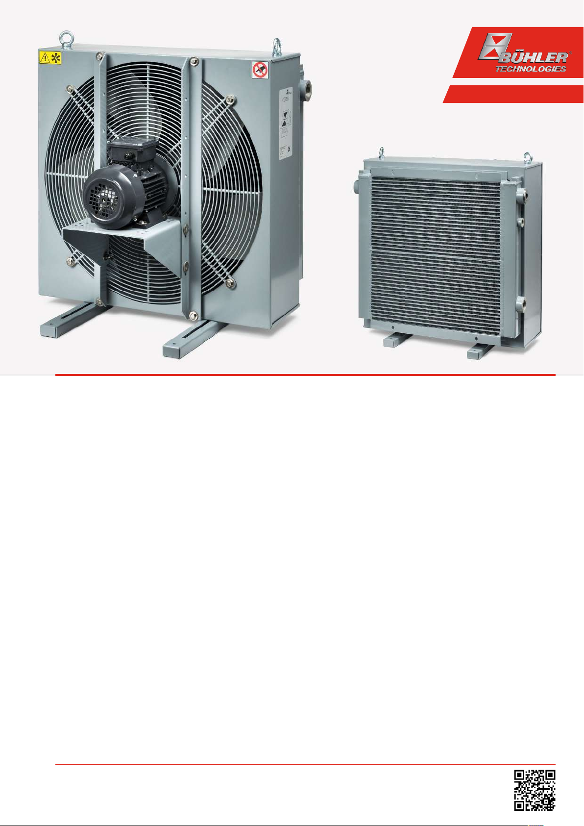
Oil/air cooler
BLK
Installation and Operation Instructions
Original instructions
BE350025
03/2019
Bühler Technologies GmbH, Harkortstr. 29, D-40880 Ratingen
Tel. +49 (0) 21 02 / 49 89-0, Fax: +49 (0) 21 02 / 49 89-20
E-Mail: fluidcontrol@buehler-technologies.com
Internet: www.buehler-technologies.com

Bühler Technologies GmbH, Harkortstr. 29, D-40880 Ratingen
Tel. +49 (0) 21 02 / 49 89-0, Fax: +49 (0) 21 02 / 49 89-20
Internet: www.buehler-technologies.com
E-Mail: fluidcontrol@buehler-technologies.com
Read this instruction carefully prior to installation and/or use. Pay attention particularly to all advises and safety instructions to prevent injuries. Bühler Technologies can not be held responsible for misusing
the product or unreliable function due to unauthorised modifications.
All rights reserved. Bühler Technologies GmbH 2019
Document information
Document No.......................................................... BE350025
Version......................................................................... 03/2019

BLK
Contents
1 Introduction..................................................................................................................................................................................................................... 2
1.1 Intended use .........................................................................................................................................................................................................2
1.2 Model key............................................................................................................................................................................................................... 2
1.3 Scope of delivery.................................................................................................................................................................................................. 2
2 Safety instructions......................................................................................................................................................................................................... 3
2.1 Important advice................................................................................................................................................................................................. 3
2.2 General hazard warnings ................................................................................................................................................................................. 3
3 Transport and storage .................................................................................................................................................................................................. 5
4 Installation and connection........................................................................................................................................................................................6
4.1 Requirements to the installation site............................................................................................................................................................6
4.2 Installing the unit................................................................................................................................................................................................6
4.2.1 Installing swivel nuts in the fitting body ..................................................................................................................................... 6
4.3 Hydraulic connection ......................................................................................................................................................................................... 7
4.4 Electrical connections ........................................................................................................................................................................................ 7
4.4.1 Electrical connections BLK 1-phase ................................................................................................................................................. 8
4.4.2 Electrical connection temperature switch TSA........................................................................................................................... 8
5 Operation and control ................................................................................................................................................................................................ 10
5.1 Before starting ................................................................................................................................................................................................... 10
5.2 During starting ..................................................................................................................................................................................................10
6 Maintenance...................................................................................................................................................................................................................11
6.1 Cleaning and disassembly of the cooler matrix ....................................................................................................................................... 12
6.2 Cleaning the cooler matrix inside ................................................................................................................................................................ 12
6.3 Cleaning the fan case ........................................................................................................................................................................................13
6.4 Replacing fan parts............................................................................................................................................................................................13
7 Service and repair......................................................................................................................................................................................................... 14
7.1 Troubleshooting ................................................................................................................................................................................................ 14
8 Disposal............................................................................................................................................................................................................................15
9 Appendices..................................................................................................................................................................................................................... 16
9.1 Technical data .................................................................................................................................................................................................... 16
9.1.1 Basic data (at 50 Hz frequency) ......................................................................................................................................................17
9.1.2 Performance curves frame size 1-6................................................................................................................................................18
9.1.3 Performance curves frame size 7-10 .............................................................................................................................................18
9.2 Dimensions ......................................................................................................................................................................................................... 19
9.3 Functional diagram ......................................................................................................................................................................................... 20
9.4 Installation torques and clamping range for cable fitting................................................................................................................... 21
9.5 Screw torques ..................................................................................................................................................................................................... 21
9.6 Hose torques....................................................................................................................................................................................................... 21
9.7 Calculations ........................................................................................................................................................................................................ 21
9.7.1 Calculating viscosity ..........................................................................................................................................................................21
9.7.2 Table of operational viscosity for VG oil ..................................................................................................................................... 22
9.7.3 Calculating the pressure loss ......................................................................................................................................................... 22
9.8 Pressure loss in straight pipes.......................................................................................................................................................................22
10 Attached documents...................................................................................................................................................................................................24
iBühler Technologies GmbHBE350025 ◦ 03/2019

BLK
Number of motor contacts
Frame size
BLK 4.6- IBx - T50
To also have a bypass and/or thermal contact, the specification will be added to the type
designation:
Bypass version
AB
IB
ITB
ATB
x
external bypass
internal bypass
internal temperature-dependent bypass 2 bar / 45 °C
external temperature-dependent bypass 2 bar / 45 °C
bypass value 2 bar, 5 bar, 8 bar
Temperature switch
T50, T60
T70, T80
Temperature in °C, specification see
separate data sheet
BLK 4.6- IBx - T50
(BLK 2-10)
(BLK 3-9)
(BLK 3-9)
(BLK 2-9)
1 Introduction
1.1 Intended use
BLK oil/air coolers are suited for the cooling of oils in hydraulic and lubrication systems. Their scope is given by their specifications. The use in other applications is not permitted without confirmation by Bühler Technologies GmbH.
1.2 Model key
1.3 Scope of delivery
– 1 x Oil/air cooler
– Product documentation
2 Bühler Technologies GmbH BE350025 ◦ 03/2019
BLK
DANGER
WARNING
CAUTION
NOTICE
2 Safety instructions
2.1 Important advice
Operation of the device is only valid if:
– the product is used under the conditions described in the installation- and operation instruction, the intended application
according to the type plate and the intended use. In case of unauthorized modifications done by the user Bühler Technologies GmbH can not be held responsible for any damage,
– when complying with the specifications and markings on the nameplates.
– the performance limits given in the datasheets and in the installation- and operation instruction are obeyed,
– monitoring devices and safety devices are installed properly,
– service and repair is carried out by Bühler Technologies GmbH,
– only original spare parts are used.
This manual is part of the equipment. The manufacturer keeps the right to modify specifications without advanced notice. Keep
this manual for later use.
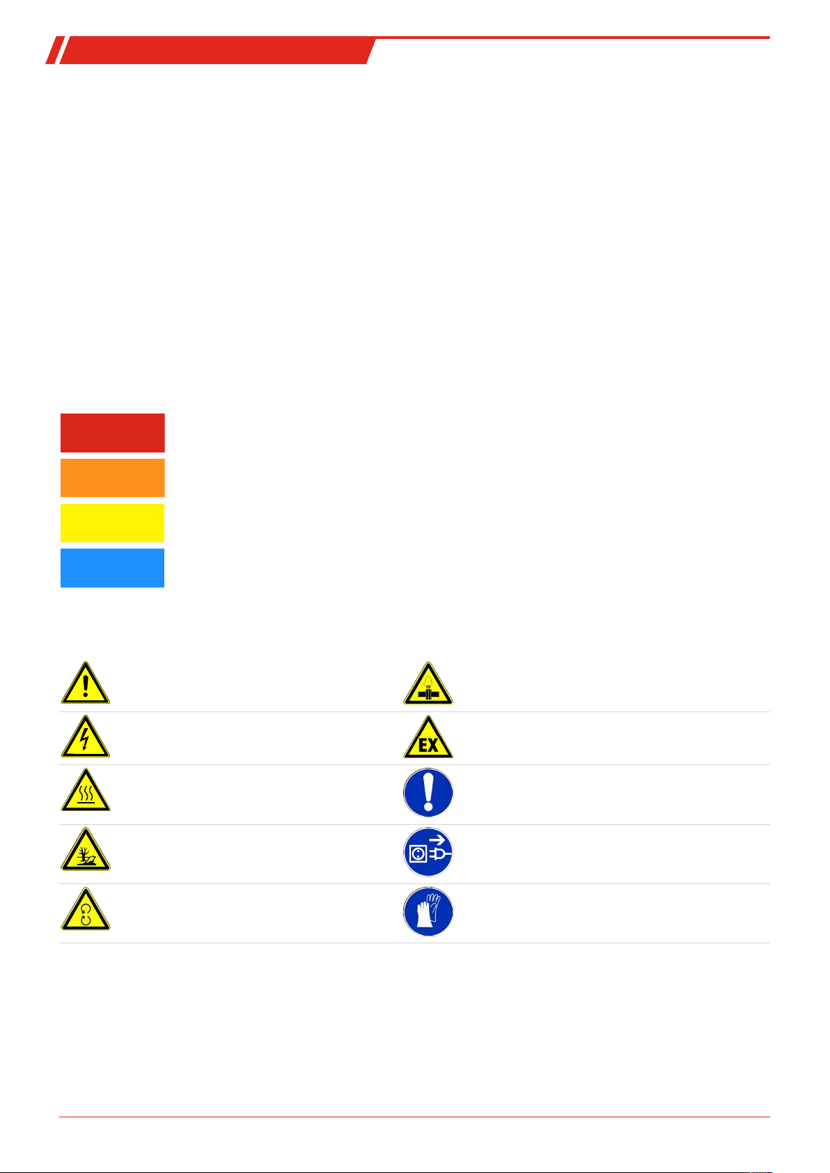
Signal words for warnings
Signal word for an imminent danger with high risk, resulting in severe injuries or death if not avoided.
Signal word for a hazardous situation with medium risk, possibly resulting in severe injuries or death if not
avoided.
Signal word for a hazardous situation with low risk, resulting in damaged to the device or the property or
minor or medium injuries if not avoided.
Signal word for important information to the product.
Warning signs
In this manual, the following warning signs are used:
Warning against hazardous situations Warning against high pressure
Warning against electrical voltage Warning against potentially explosive atmospheres
Warning against hot surface General notice
Warning against environmental hazard Disconnect from mains
Warning against rotating parts Wear protection gloves
2.2 General hazard warnings
The equipment must be installed by a professional familiar with the safety requirements and risks.
Be sure to observe the safety regulations and generally applicable rules of technology relevant for the installation site. Prevent
malfunctions and avoid personal injuries and property damage.
3Bühler Technologies GmbHBE350025 ◦ 03/2019
BLK
The operator of the system must ensure:
– Safety notices and operating instructions are available and observed,
– The respective national accident prevention regulations are observed,
– The permissible data and operational conditions are maintained,
– Safety guards are used and mandatory maintenance is performed,
– Legal regulations are observed during disposal,
– compliance with national installation regulations.
– Nearby equipment is EMC protected, e.g. through shielding.
– The current and voltage supply for the aggregate has a (mains) separator with adequate switching capacity. National re-
quirements must be observed.
Maintenance, Repair
Please note during maintenance and repairs:
– Repairs to the unit must be performed by Bühler authorised personnel.
– Only perform conversion-, maintenance or installation work described in these operating and installation instructions.
– Always use genuine spare parts.
Always observe the applicable safety and operating regulations in the respective country of use when performing any type of
maintenance.
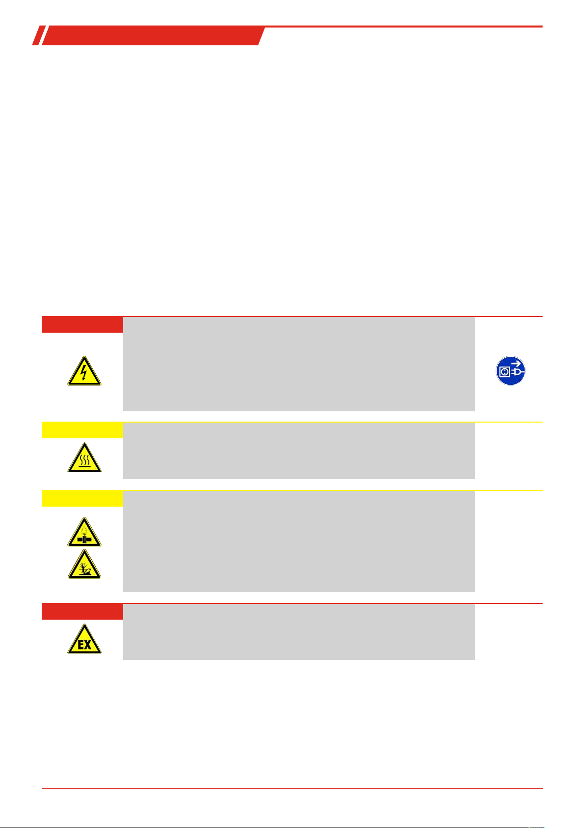
DANGER Electrical voltage
Electrocution hazard.
a) Disconnect the device from power supply.
b) Make sure that the equipment cannot be reconnected to mains unintentionally.
c) The device must be opened by trained staff only.
d) Regard correct mains voltage.
CAUTION Hot surface
Burning hazard
Let the device cool down before maintaining.
CAUTION High pressure
Hazard of injury due to flung off parts or oil, environmental hazard due to oil.
a) Before starting any maintenance or repair to the oil circuit, make sure that the device
is depressurized. This applies to the locking screws as well.
b) Avoid environmental pollution (oil spills) during cleaning or maintenance of the oil
circuit.
c) Use drip pans.
DANGER Potentially explosive atmosphere
Explosion hazard if used in hazardous areas.
The device is not suitable for operation in hazardous areas with potentially explosive atmospheres.
4 Bühler Technologies GmbH BE350025 ◦ 03/2019

BLK
3 Transport and storage
The product should only be transported inside the original packaging or a suitable alternative. Ensure secure fastening and
mooring.
Units with air coolers have M10 eye bolts at the top of cooler housing for transport. Please note, due to the variety of versions the
mounting bracket is not located at the exact centre of gravity and the cooler may swing when hoisted. Never hoist by the M8
threads in the cooling elements!
Only use the engine transport eyes to hoist the engine without add-ons.
Do not use the eye bolts according to DIN 580 in ambient temperatures below -20°C. The eye bolts could fracture in these temperatures, injuring personnel and/or damage the system.
Do not strain the eye bolts more than 45° in the thread direction.
When not in use, the equipment must be protected from moisture and heat. They must be stored in a covered, dry, dust-free
room at room temperature.
WARNING Crushing hazard
Crushing hazard during equipment transport and set-up.
Use the correct hoisting gear to prevent injuries during hoisting.
Be sure the hoisting gear is free from defects and approved for the weight of the oil/air
cooler.
Ensure secure fastening and mooring when transporting.
5Bühler Technologies GmbHBE350025 ◦ 03/2019

BLK
4 Installation and connection
4.1 Requirements to the installation site
Aggregate
The aggregate must be set up to allow for unobstructed air flow and adequate room for maintenance/repairs. When installed
outdoors, be sure to consider the motor protection rating (standard: IP 55) and ensure adequate protection from the weather.
Air cooler
The aggregate must be set up to allow for unobstructed air flow and adequate room for maintenance/repairs. When installed
outdoors, be sure to consider the motor protection rating and ensure adequate protection from the weather.
The cooler must be located in such a way that the air flowing through the matrix has free flow on entry and exit. The distance
between air intake or air outlet to the nearest surrounding obstacle should be at minimum half the height of the matrix. Free
air flow must be provided.If the cooler is to be sited near to working personnel, the effect of hot draught and noise emissions
must be taken into account.
If the cooler is installed in closed space, ensure sufficient air circulation. Avoid back flow of warmed air. If necessary, the room
must be vented.
Due to lower temperatures with respect to closed rooms, the cooling capacity outside raises, but on the other hand higher start
up pressure may result due to higher oil viscosity. In this case, consider a bypass valve and / or a heating.
The rotating fan might lead to static charging. Therefore sensitive equipment like electronics should be kept away from the
device.
4.2 Installing the unit
The units are screwed in place at the attachment points using screws. Be sure the support structure is sized adequately. To protect the system from damage, the connections must be stress free. We recommend using flexible hoses. Be sure the hose is
stable against negative pressure, e.g. steel wire reinforced. Avoid possible leaks in the circuit to prevent environmental damages. If necessary, use an oil pan. Protect the aggregate from mechanical impact.
4.2.1 Installing swivel nuts in the fitting body
Proceed as follows:
– Carefully slide the preinstalled pipe end into the 24° cone on the fitting body.
– Tighten the swivel nut until a considerable increase in force can be felt (fixed point).
– Use a suitable spanner to tighten the swivel nut a 1/12 turn more (30°) beyond the fixed point. A marker line on the swivel
nut and the fitting body facilitates observing the correct tightening angle.
Tube
A.D.
6 G 1/8" 18 13
8 G 1/4" 35 30
10 G 1/4" 35 30
12 G 3/8" 70 60
15 G 1/2" 90 80
18 G 1/2" 90 80
22 G 3/4" 180 140
28 G 1" 310 200
35 G 1 1/4" 450 400
42 G 1 1/2" 540 450
Thread Torque (Nm) for straight
screwed plug
Torque (Nm) sealing plug
6 Bühler Technologies GmbH BE350025 ◦ 03/2019
BLK
4.3 Hydraulic connection
Carry out the hydraulic connection as described in the attached data. Connect the lines stress and vibration free, so typically using hoses.
Be sure to use suitable lines (with regard to pressure, fluid resistance, environmental influences, fire) when connecting to the
hydraulic-, lubrication circuit. Tighten the hose lines with a suitable torque (see appendix).
Contaminated fluids impact the life of the cooling system, we therefore recommend a purity class of 23/19/13 per ISO4406.
If your hydraulic system is equipped with control or shut-off valves, we recommend protecting the cooling system with a pressure relief valve. No pressure relief valves are factory installed in the cooler.
When installing an air cooler in return lines, sudden changes to the flow rate can potentially cause significant pressure peaks
which even safety relief valves cannot dampen. The limits for the static pressure must not exceed max. 21bar, or 15bar for dynamic pressure peaks. Otherwise an off-line cooler must be used.
The coolers are optionally available with external or internal bypass valve in the cooling matrix.
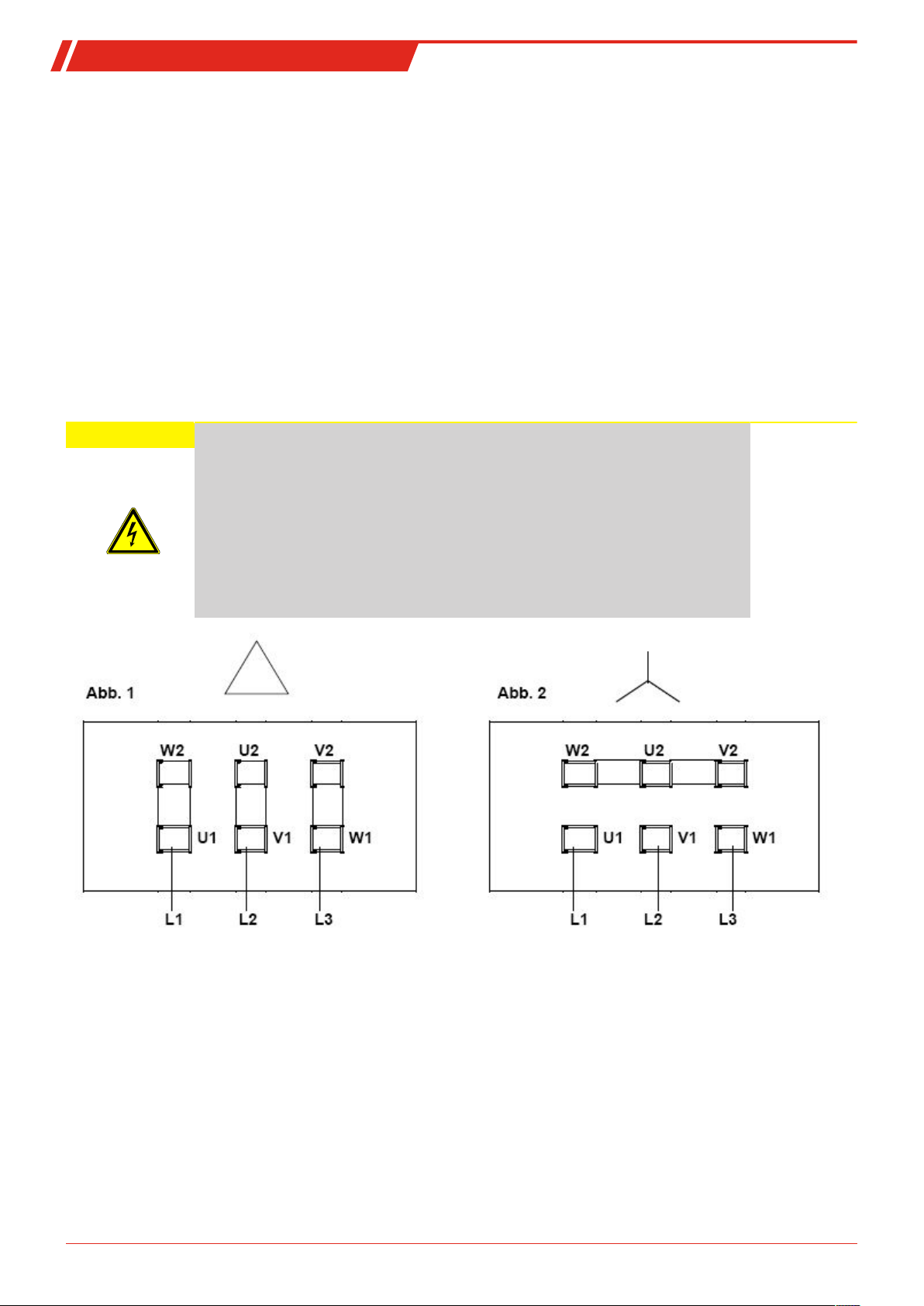
4.4 Electrical connections
CAUTION Electrical voltage
Wrong mains voltage may damage the device.
Installation of the device shall be performed by trained staff only. Regard the voltage
given on the type plate. Make sure that the cables have sufficient strain relief.
Fusing
Fusing has to be done due to local standards!
Polarity
Take care of the directional rotation of the motor. The fan rotates counter clockwise
when regarded form the motor’s side!
Watch the direction arrow on the sticker.
The direction of rotation can be changed by reversing any two phases.
Use the applicable local regulations to determine the safety values and the cross-sections of connection leads. The motor and, if
equipped, starting devices must be connected to protective earth.
Lead fuses protect the cables in case of a short circuit, but are not sufficient to protect the motor coils from burning due to overload. Therefore, install an adequate motor circuit breaker with high precision range of adjustment for thermal protection to protect the motor against overload and operation with two phases
Adjust the motor circuit breaker according to the nominal value specified on the type plate of the motor. Operation outside the
specified mains voltage and frequency range limits is prohibited.
Take appropriate measures to protect energised parts from being touched by persons and/or interference from foreign objects.
The operator of the equipment is responsible for ensuring lightning protection.
Connect the protective earth of the motor to the protective earth on site. Protective earth per DINVDE0100 must be connected
to the marked earth lead terminal.
7Bühler Technologies GmbHBE350025 ◦ 03/2019
 Loading...