

Page 1
Analysentechnik
Installation and Operation Instructions
Original instructions
Portable Oxygen Analyser
BA 4510
BE550013
09/2018
Bühler Technologies GmbH, Harkortstr. 29, D-40880 Ratingen
Tel. +49 (0) 21 02 / 49 89-0, Fax: +49 (0) 21 02 / 49 89-20
E-Mail: analyse@buehler-technologies.com
Internet: www.buehler-technologies.com
Page 2

Bühler Technologies GmbH, Harkortstr. 29, D-40880 Ratingen
Tel. +49 (0) 21 02 / 49 89-0, Fax: +49 (0) 21 02 / 49 89-20
Internet: www.buehler-technologies.com
E-Mail: analyse@buehler-technologies.com
Read this instruction carefully prior to installation and/or use. Pay attention particularly to all advises and safety instructions to prevent injuries. Bühler Technologies can not be held responsible for misusing
the product or unreliable function due to unauthorised modifications.
All rights reserved. Bühler Technologies GmbH 2018
Document information
Document No...........................................................BE550013
Version.........................................................................09/2018
Page 3

BA 4510
Table of Contents
1 Introduction..................................................................................................................................................................................................................... 2
1.1 Intended Use......................................................................................................................................................................................................... 2
1.2 Ordering instructions ........................................................................................................................................................................................ 2
1.3 Scope of delivery.................................................................................................................................................................................................. 2
1.4 BA 4510 Layout......................................................................................................................................................................................................2
1.4.1 Principle of Measurement .................................................................................................................................................................2
1.4.2 Measuring Requirements ..................................................................................................................................................................3
1.4.3 General Design ..................................................................................................................................................................................... 4
1.4.4 BA 4510 Layout...................................................................................................................................................................................... 6
2 Safety instructions.........................................................................................................................................................................................................8
2.1 Important Information......................................................................................................................................................................................8
2.2 General hazard warnings .................................................................................................................................................................................9
3 Transport and Storage................................................................................................................................................................................................ 10
4 Installation and connection....................................................................................................................................................................................... 11
4.1 Installation site requirements........................................................................................................................................................................ 11
4.2 Preparing for Operation................................................................................................................................................................................... 11
5 Operation and Parametrisation ...............................................................................................................................................................................13
5.1 Operation..............................................................................................................................................................................................................13
5.1.1 Switching On and Measurement Display ................................................................................................................................... 13
5.1.2 Setting the Sample Gas Flow Rate................................................................................................................................................. 13
5.1.3 Measurement Monitoring............................................................................................................................................................... 13
5.1.4 Status/Error Messages ......................................................................................................................................................................13
5.2 Parametrisation................................................................................................................................................................................................. 14
5.2.1 Adjustable Parameters ..................................................................................................................................................................... 14
5.2.2 Programming Menus........................................................................................................................................................................14
5.3 Calibration............................................................................................................................................................................................................17
5.3.1 Zero Gas Calibration.......................................................................................................................................................................... 17
5.3.2 Span Gas Calibration......................................................................................................................................................................... 17
6 Maintenance.................................................................................................................................................................................................................. 18
6.1 Replacing the Fuse ............................................................................................................................................................................................ 18
7 Service and repair.........................................................................................................................................................................................................20
7.1 Troubleshooting ............................................................................................................................................................................................... 20
8 Disposal............................................................................................................................................................................................................................21
9 Appendix.........................................................................................................................................................................................................................22
9.1 Technical Data ....................................................................................................................................................................................................22
9.2 Basics of using potentiometric ZrO2 solid electrolyte sensors in optimal combustion processes ...........................................23
9.3 Activated Carbon Filter: Description and Use........................................................................................................................................... 25
9.3.1 Filter Design .........................................................................................................................................................................................25
9.3.2 Filter use and functionality ............................................................................................................................................................ 26
9.3.3 Replacing the Activated Carbon.................................................................................................................................................... 26
10 Attached Documents................................................................................................................................................................................................... 27
iBühler Technologies GmbHBE550013 ◦ 09/2018
Page 4

BA 4510
1 Introduction
1.1 Intended Use
The BA 4510 analyser is used for continuous measurement of the oxygen concentration of industrial, laboratory and inert gases
as well as in the process of mixing and manufacturing special forming gases. Here, in inert gases the concentration of free oxygen, and in gas mixtures the concentration of bonded oxygen can be measured. The oxygen content of sample gas is measured
and displayed continuously. Deviations from the configurable set points are signalled. The purity and required protective effect
of inert gases is monitored. So specific production processes under inert gas can be monitored.
1.2 Ordering instructions
Device model
Item no. Description
55 15 000 BA 4510
55 15 001 BA 4510 KIZ
1.3 Scope of delivery
– Analyser
– Product documentation
– Connection/mounting accessories (optional)
1.4 BA 4510 Layout
1.4.1 Principle of Measurement
Determining the oxygen concentration in gases is often an established requirement in gases in the industrial sector, but also in
laboratories. Gases with an obvious oxygen concentration which fluctuates based on the temperature are most commonly
measured. The BA 4510 uses the NERNST equation as the basis for determining the oxygen concentration in gases.
U
=
RT
zF
ln
p
O
p
O
2
,sample gas
2
,air
Where:
U: Cell voltage in mV
R: Molar gas constant, R=8.31441 J/mol*K
T: Measuring temperature in K
F: Faraday constant, F=9.6485*10
4
C/mol
z: Valency of involved ions
Po
2Air:
Partial pressure of oxygen on the reference electrode in dry air in Pa
Po
2samplegas:
Partial pressure of oxygen on the measuring electrode in sample gas in Pa
The BA 4510 has a sensor which uses the conductivity of oxide ions in zirconium dioxide ceramics with stabilising additives. The
conductivity of the oxide ions of zirconium dioxide increases exponentially with the temperature and reaches adequate values
above 600°C (1112°F).
The ceramic oxide ion conductor is used as a gas-tight tube through which gas to be measured is conducted. The ceramic tube is
axially symmetrical inside a thermally well-insulated electric oven. The electrodes of the galvanic measuring cell are platinum.
The electrode on the outside of the tube, surrounded by dry air, serves as a reference electrode with a constant, established electrode potential.
Provided the total pressures of the gasses are about equal at both electrodes, volume concentrations can be expected instead of
partial pressures. After adding the numeric value for the constants in equation
(I)
results in the following conditional equation
for the oxygen concentration.
2 Bühler Technologies GmbH BE550013 ◦ 09/2018
Page 5

BA 4510
=
2
,air
=
20.64
U
T
U
T
φ
φ
φ
●
●
e
e
●
O
)(
)(
46.42
zF
R
O
2
,sample gas
O
2
,sample gas
Where:
Φ oxygen concentration in the sample gas in Vol.%
U: Potential difference in mV
T: Measuring temperature in K
20.64 oxygen concentration in air with a relative humidity of 50 % in Vol.%
1.4.2 Measuring Requirements
1.4.2.1 General Information
Sample gas can have free or bonded oxygen. Without sufficient "
free oxygen
" in addition to combustible gas components, a
chemical balance will occur on the hot board electrode. The cell then measures the concentration of the "
equilibrium oxygen
".
(The basics are explained in the appendix Basics of using potentiometric ZrO2 solid electrolyte sensors in optimal combustion
processes [> page23].)
Here the following dependencies apply:
U ~ T
Contains free oxygen
U
~
1
T
Contains bonded oxygen
The conditional equation
(II)
applies to both sample gases with free oxygen as well as for reduced gas mixtures which only con-
tain bonded oxygen, e.g. in H2/H2O or CO/CO2 mixtures.
1.4.2.2 Sample Gas Flow Rate
The sample gas flow rate must be between 5 and 10 L/h to ensure exact measurement. If the low flow rate is too low, the contamination effects of the gas lines (leaks, permeabilities, desorptions) will cause reading errors. If the flow rate is too high, asymmetric cooling of the sensor can cause measurement errors.
A differential pressure sensor measures the gas flow. When over- or underrunning the limit, the device will output an error message yet continue measuring.
When operating the device with the internal gas pump, the flow rate controls the pump. The gas flow will always be set to an
optimal flow rate of 7 L/h.
1.4.2.3 Measurement Accuracy
The manufacturer only guarantees a measuring error of < 5% (relative error) when measuring oxygen concentrations with an
order of 2*105 …10 ppm (this manual uses the unit ppm is used in the sense of Vol.-ppm). When measuring oxygen concentrations of 10…1 ppm, the relative error is under 5 % provided the gas supply has no leaks or permeabilities.
When measuring oxygen concentrations < 10 ppm, user must consider the following aspects when analysing the measured
value:
– composition of the sample gas (e.g. presence of reducing gas components)
– special production process conditions (e.g. material components)
– sample gas temperature
3Bühler Technologies GmbHBE550013 ◦ 09/2018
Page 6
BA 4510
NOTICE
To minimise the measuring error when measuring minimal oxygen concentrations, ensure the following measurement and equipment requirements are met:
a) Choose a location for extracting the sample gas to rule out any layers forming at the
extraction site.
b) The transport path for the sample gas to the measuring cell must be as short as pos-
sible to prevent a shift in the chemical balance along the way as best possible.
c) All gas supply and discharge lines must be absolutely tight.
d) Measuring oxygen concentrations < 1000 ppm requires stainless steel lines.
e) If the sample gas contains reducing components (e.g. alcohols), the concentration of
free oxygen cannot be determined, as chemical reactions occur at the electrode. In
these cases it is advisable to pass the sample gas through an activated carbon filter
before the gas inlet.
1.4.3 General Design
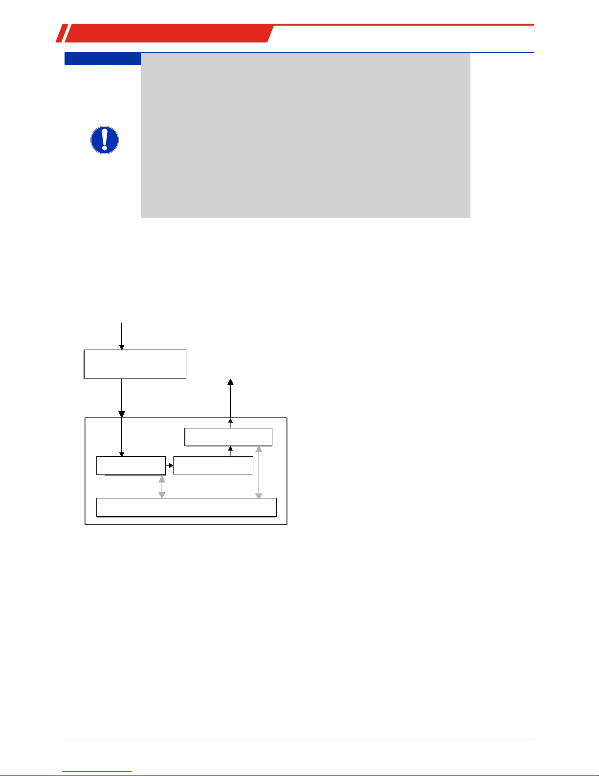
1.4.3.1 General Overview
This device is available in a portable, compact laboratory design. The general structure of the device is shown in figure 1.
Pressure regulator
(needle valve, optional
Gas inlet
Gas outlet
Flow meter
Measuring cell
Diaphragm pumps
Analysis electronics with display
Data exchange
Fig.1: General layout, components
The sample gas is pushed into the measuring cell at minimal overpressure or, on the version with pump, suctioned through the
measuring cell. A needle valve and/or a pressure regulator can be installed before the gas inlet to control the flow rate. On the
version with pump the flow rate is kept at a constant by regulating the pump output.
4 Bühler Technologies GmbH BE550013 ◦ 09/2018
Page 7
BA 4510
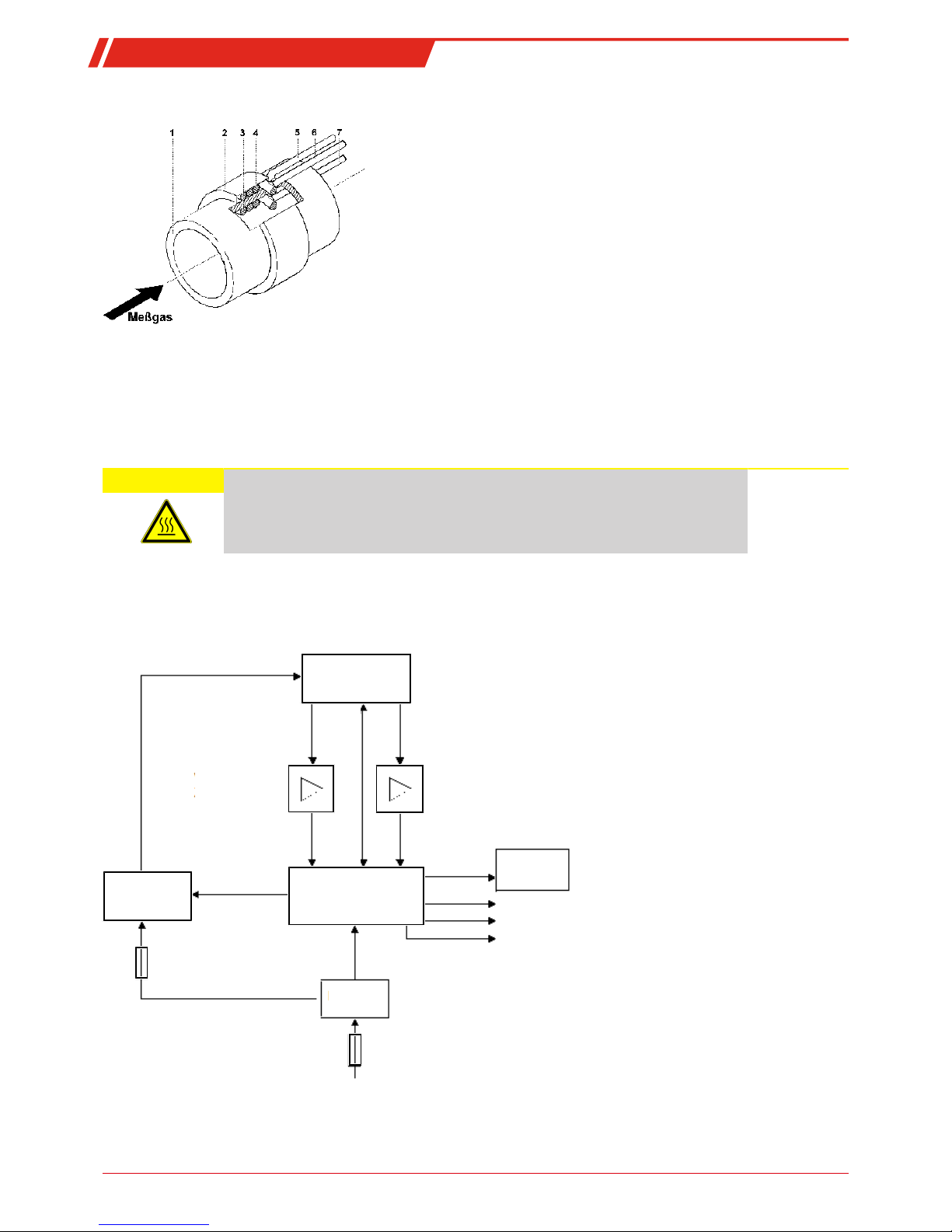
1.4.3.2 Solid Electrolyte Measuring Cell Design Principle
1 Ceramic tube
2 Ceramic cover for the reference electrode
3 Measuring electrode
4 Reference electrode
5 Thermocouple
6 Reference electrode connecting wire
7 Measuring electrode connecting wire
The measuring cell is a zirconium dioxide ceramic tube with two electrodes made from platinum wire. Inside the tube the
sample gas flows through is the measuring electrode. The electrode outside of the tube serves as reference electrode with constant electrode potential. The electrodes and the ceramic tube from a voltaic cell (solid electrolyte measuring cell).
For favourable oxide ions conductivity values of the zirconium dioxides and prevent interference reactions due to unbalance
with flammable components in the sample gas, the measuring cell is heated to 750 °C. A thermocouple on the measuring cell determines the current measuring temperature T. An electronic control circuit ensures a constant measuring temperature.
CAUTION Risk of overheating
Overheating will damage the device.
Heating results in heat loss in the inert gas measuring device. Therefore do not place
items on or in close proximity of the device.
The block diagram in the next chapter how measurements are processed electronically.
1.4.3.3 Electronic Processing of Measurements
The following block diagram outlines how signals are processed.
Measuring cell
Cell voltage
amplifier
Thermovoltage
amplifier
On-screen
keyboard
Heater
control
Microcontroller
Power
supply
0.8 A (resettable)
1.0 A
100...24 0V AC, 47...63 Hz
Relay output
RS232
Analog output
Measuring cell monitor
Fig.2: BA 4510 block diagram
5Bühler Technologies GmbHBE550013 ◦ 09/2018
Page 8
BA 4510
1.4.4 BA 4510 Layout
1.4.4.1 Mechanical Design
All components (main electronics, flow meter, pump, mains filter, measuring cell) are located inside a portable housing.
1.4.4.2 Electric Supply
The BA 4510 connects to the mains via fixed cord set.
The BA 4510 is designed as a tabletop device. The operating position is horizontal with a maximum tilt of 30°.
1.4.4.3 Front
The displays and controls are located in the front. A display shows the measured value in Vol.% or Vol.-ppm, depending on the
value and programming.
1 Vol.% corresponds to 104 Vol.-ppm, 1 Vol.-ppm corresponds to 0.0001 Vol.%.
A light diode serves as status light and indicates specific operating conditions or warnings in colour and possibly flashing (see
Operation and Control)
On the right is the keyboard used to select the view or program the device.
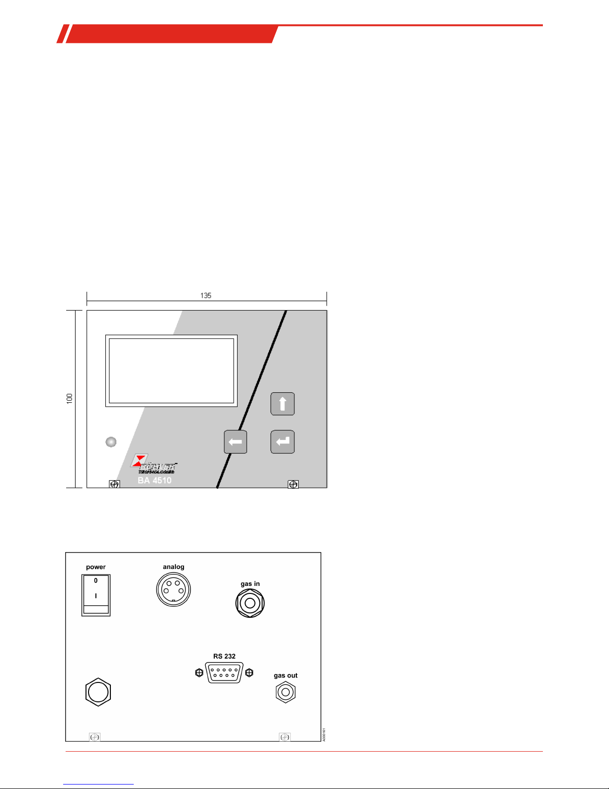
1.4.4.4 Back panel
At the back of the device are the gas inlet and outlet, a d-sub port for the RS232 interface and the mains switch. The mains cable
is fixed to the device.
6 Bühler Technologies GmbH BE550013 ◦ 09/2018
Page 9

BA 4510
1.4.4.5 Pin assignment
Serial port
RS232
Transfer rate max. 19200 baud, adjustable
Stopbits 1
Data bits 8
Parity none
Handshake without
Serial interface protocol (CR= carriage return)
Input Response Parameter
M2CR M2x.xxExxCR Oxygen concentration in ppm
A1CR A1xxxCR Cell voltage in mV
A2CR A2xxxCR Measuring temperature in °C
Error messages:
0 ERROR0 Transmission error
1 ERROR1 Warm up
2 ERROR2 Cell temperature too low
3 ERROR3 Thermocouple defect
4
5
6 ERROR6 System error
Analog output
Output
4 - 20 mA
Output
potential-free
Pin 1,2 measurement signal output 4-20 mA
Pin 3,4 potential-free connections for limit relays:
Note:
If the limit is breached, the limit relay opens and triggers a
general alarm.
7Bühler Technologies GmbHBE550013 ◦ 09/2018
Page 10
BA 4510
2 Safety instructions
2.1 Important Information
Operation of the device is only valid if:
– the product is used under the conditions described in the installation- and operation instruction, the intended application
according to the type plate and the intended use. In case of unauthorized modifications done by the user Bühler Technologies GmbH can not be held responsible for any damage,
– when complying with the specifications and markings on the nameplates.
– the performance limits given in the datasheets and in the installation- and operation instruction are obeyed,
– monitoring devices and safety devices are installed properly,
– service and repair is carried out by Bühler Technologies GmbH,
– only original spare parts are used.
This manual is part of the equipment. The manufacturer keeps the right to modify specifications without advanced notice. Keep
this manual for later use.
Please particularly note the following analyser instructions:
– Always transport the equipment diligently and carefully. Strong impact and shock may damage the measuring cells in the
analyser or shorten their life!
– Disconnect from the mains before opening the device.
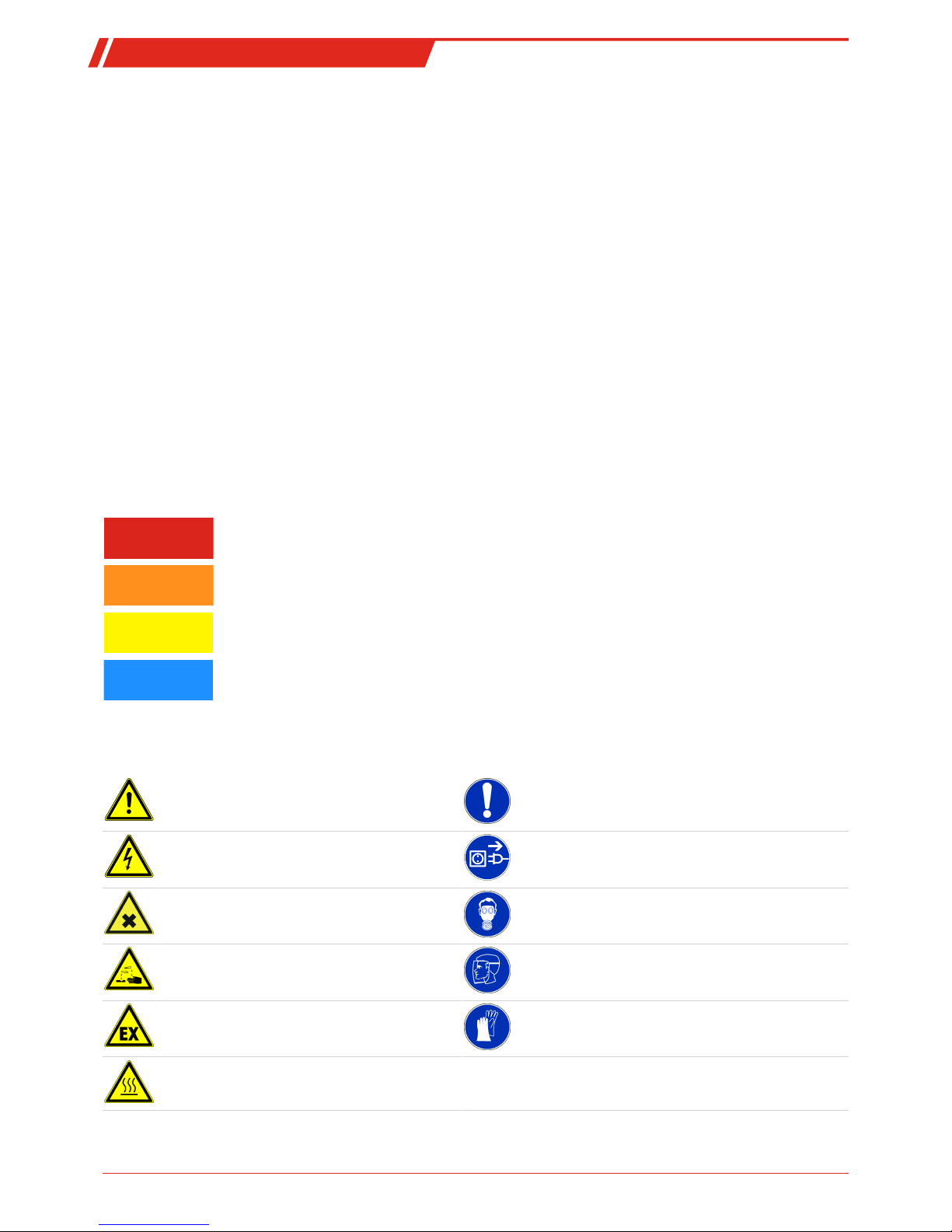
Signal words for warnings
DANGER
Signal word for an imminent danger with high risk, resulting in severe injuries or death if not avoided.
WARNING
Signal word for a hazardous situation with medium risk, possibly resulting in severe injuries or death if not
avoided.
CAUTION
Signal word for a hazardous situation with low risk, resulting in damaged to the device or the property or
minor or medium injuries if not avoided.
NOTICE
Signal word for important information to the product.
Warning signs
In this manual, the following warning signs are used:
Warning against hazardous situations General notice
Warning against electrical voltage Disconnect from mains
Warning against respiration of toxic gases Wear respirator
Warning against acid and corrosive substances Wear eye/face protection
Warning against potentially explosive atmospheres Wear protection gloves
Warning against hot surface
8 Bühler Technologies GmbH BE550013 ◦ 09/2018
Page 11

BA 4510
2.2 General hazard warnings
The equipment must be installed by a professional familiar with the safety requirements and risks.
Be sure to observe the safety regulations and generally applicable rules of technology relevant for the installation site. Prevent
malfunctions and avoid personal injuries and property damage.
The operator of the system must ensure:
– Safety notices and operating instructions are available and observed,
– The respective national accident prevention regulations are observed,
– The permissible data and operational conditions are maintained,
– Safety guards are used and mandatory maintenance is performed,
– Legal regulations are observed during disposal.
Maintenance, Repair
Please note during maintenance and repairs:
– Repairs to the unit must be performed by Bühler authorised personnel.
– Only perform conversion-, maintenance or installation work described in these operating and installation instructions.
– Always use genuine spare parts.
Always observe the applicable safety and operating regulations in the respective country of use when performing any type of
maintenance.
DANGER Electrical voltage
Electrocution hazard.
a) Disconnect the device from power supply.
b) Make sure that the equipment cannot be reconnected to mains unintentionally.
c) The device must be opened by trained staff only.
d) Regard correct mains voltage.
DANGER Toxic, acidic gasses
Sample gas / calibrating gas can be harmful.
a) If necessary, ensure a safe gas discharge.
b) Switch off the gas supply before performing maintenance and protect from opening
inadvertently.
c) Protect yourself from toxic / corrosive gasses when performing maintenance. Wear
suitable protective equipment.
DANGER Potentially explosive atmosphere
Explosion hazard if used in hazardous areas.
The device is not suitable for operation in hazardous areas with potentially explosive atmospheres.
Do not expose the device to combustible or explosive gas mixtures.
9Bühler Technologies GmbHBE550013 ◦ 09/2018
Page 12

BA 4510
3 Transport and Storage
Transport
The device is sensitive to shock and vibration. Therefore, where possible, transport in the original packaging or large, sturdy
packaging at a minimum consisting of 3 layer carton, plastic or aluminium sheet. Line the inside of the packaging with padding
at least 10 cm thick on all sides.
The device should be marked fragile for shipping.
Removal from service and storage
Purge the device with dry nitrogen or dry air before removing from service for extended periods. Then close the gas inputs and
outputs to prevent dirt, dust, and moisture from entering the device.
Store the device in a dry, ventilated, dust-free room. Cover the device with suitable packaging to protect it from liquids and dirt.
Never place objects on top of the device during storage.
Storage temperature: -20°C …+50°C (-4°F…+122°F)
10 Bühler Technologies GmbH BE550013 ◦ 09/2018
Page 13

BA 4510
4 Installation and connection
4.1 Installation site requirements
The inert gas measuring device must be set up in a dry and mostly dust-free location on a sturdy, level surface.
– An earthed wall socket with 10 A fuse, preferably on a separate circuit, must be installed in the immediate vicinity of the in-
stallation site to connect to the mains.
– No heat sources or equipment emitting strong magnetic fields (e.g. motors and transformers) may be located near the in-
stallation site.
– The operating position of the device is horizontal.
CAUTION Heat built-up
Insufficient ventilation will damage the device.
Always install the device horizontal. Vertical installation is prohibited due to potential
damage to the device from heat building up.
CAUTION Ingress of liquids
Water entering the device can cause serious damage to the device, potentially beyond
repair.
Do not place objects containing water on or in the immediate vicinity of the device!
4.2 Preparing for Operation
NOTICE
When transporting from cold environments to the installation site with higher ambient
temperatures or humidity, allow to
sit for at least two hours
to acclimate.
Install the device in the desired location.
– Install lines from the measuring point to the gas inlets and outlets. Ensure the lines are tight.
– If pressure limitation is required, install a pressure regulator with needle valve (available from the manufacturer of the
device) before the gas inlet.
– If the sample gas contains water vapour which could condensate inside the cold connection lines, the condensate must be
collected before the device. Water must not enter the hot measuring cell.
– An external flow meter should always be installed after the gas discharge (any leaks which may occur will not affect the
measurements at this point).
– Connect the device to the mains.
Connection options
The device can be connected by bypass (internal pump suctions the sample gas!) or via direct gas inlet (limit 0.1 bar overpressure).
Piping material
Particularly for long transport paths and unfavourable conditions, select piping to rule out oxygen permeability. The manufacturer recommends the following materials depending on the measuring conditions:
Sample gas temperature low thick PVC tubing
Higher sample gas temperature Tygon R 3603 (supplier, e.g. novodirect Kehl)
Oxygen concentration < 1000 ppm Stainless steel lines
11Bühler Technologies GmbHBE550013 ◦ 09/2018
Page 14

BA 4510
NOTICE
When installing
connections
for steel lines, the information in the appendix provided by
the manufacturer must be observed.
Silicone tubes
can cause inaccurate measurements due to their oxygen permeability.
The manufacturer therefore advises against using this type of tubing.
CAUTION Water entering the hot measuring cell
Water entering the hot measuring cell can damage it beyond repair and must therefore
be avoided.
If the sample gas contains so much water vapour there is a risk of water condensation,
inside cold tubing, a water separator must be installed before the sample gas enters the
device.
NOTICE
The sample gas can also flow with the device switched off.
12 Bühler Technologies GmbH BE550013 ◦ 09/2018
Page 15

BA 4510
5 Operation and Parametrisation
5.1 Operation
5.1.1 Switching On and Measurement Display
After preparing the inert gas measuring device for operation and installing all lines, the device can be switched on. The measuring cell reaches its operating temperature of 750°C (1382°F) after approx. 10 minutes. The current measured value will be displayed but will not be within the specified error limits until the thermal conditions inside the measuring cell are completely balanced, after about one hour.
The device enters display mode after being switched on. The display shows the value programmed in the output (typically the
current oxygen concentration) according to the selected dimension (Vol.% or ppm).
5.1.2 Setting the Sample Gas Flow Rate
NOTICE
To ensure exact measurements, set the flow rate to 5 ... 10 L/h. When measuring by bypass, the flow rate is controlled by the internal pump.
In the event of sample gas overpressure, the manufacturer recommends installing a high-quality needle valve directly at the gas
inlet of the device. Suitable needle valves are available from the manufacturer of the device. If higher pressure occurs, a pressure
regulator should be installed upstream to regulate its output pressure to approx. 100 kPa (1 bar) overpressure.
5.1.3 Measurement Monitoring
The device can be programmed for a limit, which sends alerts via relay output. The relay is open when active. (If a limit is activated this status will also appear in the status line). This signal is delayed. The response time for measurement monitoring (limit
delay) can be set to 1 to 99 seconds.
5.1.4 Status/Error Messages
Measuring cell functions are monitored during the measuring process. In the event of a failure/error, error messages are output. At the same time the relay output is activated to indicate a fault.
Status Display Note
0 OK
1 LIMIT
2 RANGE<<<
3 RANGE>>>
4 FLOW<<< < 5 L/h
5 FLOW>>> > 10 L/h
6
7
8
9 WARM UP Cell temperature too low (wait, after approx. 15 minutes 750°C (1382°F) must be reached)
10 CELL TEMP.<<< Set temp -10° and >30 min
11 THERMOCOUP. ERROR Thermocouple defect
12
13
14 SYSTEM ERROR
Status 1...8: Warnings, only alarm relay active
Status 9...14: Error, alarm relay active and current signal zero
13Bühler Technologies GmbHBE550013 ◦ 09/2018
Page 16

BA 4510
5.2 Parametrisation
5.2.1 Adjustable Parameters
Parameter Section Remarks
Display O2: 0…21 (100) Vol-% or in ppm Measuring range 100 Vol.% on request
Analog output 0…20 mA or 4…20 mA
alternatively 0…10 V or 2…10 V
Output scale Linear
Logarithmic (base 10)
Logarithmic scale recommended if the measured value spans several decades.
Suppressed zero point 0.00001…21 Vol.% or
0.1…21000.0 ppm
Advisable for optimal resolution in a certain
range
Maximum measured value 20.000…21.000 Vol.% or 200000…210000 ppm,
higher values on request
This value corresponds to the respective end
value of the analogue signal (e.g. 20 mA)
Measurement response time t901 ... 99 s Formed from arithmetical average of the
measured value
Limit 0…99.99 Vol.%
or 0…999999 ppm
Set as lower or upper limit with the symbol
">" or "<"
Limit delay 1 ... 99 s Time which must have been exceeded before
the alarm is signalled.
Transfer rate of the RS-232 port 4800, 9600, 19200 baud
Measuring gas flow rate Internal pump, switch on or off via keyboard The pumping capacity is regulated via flow
measurement
5.2.2 Programming Menus
Use the keys below the display to access the following menus (the display shows the current key configuration). Here you can al-
ways use the key to select specific parameters, which can be changed with the various keys, then press the key again to
confirm.
A main display
Flow
Status line
Pump status (on/off via key) and cell temperature
An LED indicates the following statuses:
Flashing red: Error
Green: OK
Yellow: Limit
14 Bühler Technologies GmbH BE550013 ◦ 09/2018
Page 17

BA 4510
B settings
B.1 Base settings
English, German
4800, 9600, 19200
+-9
OFF
B.2 limit
0…999999 ppm or 0…99.99 Vol.%
0…99s
B.3 Analog Output
Vol% O2, ppm O2, O2[log10] Optional:O2 NGW, H20/H2
0-20 mA or 4-20mA Optional: 0-10V or 2-10V
1-99s
15Bühler Technologies GmbHBE550013 ◦ 09/2018
Page 18

BA 4510
B.4 calibration
B.4.1 zero gas calibration
Current measured value
Zero gas always 20.64 %
Status
Calibration value
1)
1)
with this line activated, press the
Enter
key for approx. 3 s to set the calibration value to 0.0
Range calibration
Current measured value
Calibration status
Calibration value *2
*2 with this line activated, press the Enter key for approx. 3s to set the calibration value to 1.00
B.4.4 Saving
16 Bühler Technologies GmbH BE550013 ◦ 09/2018
Page 19

BA 4510
5.3 Calibration
Since the measuring system is linear, two calibration points will suffice for the check:
-Zero point
The zero point corresponds with the measurement if there is no oxygen in the measuring cell and there is neutral gas such as nitrogen in the unit.
-Measuring range (sensitivity)
The sensitivity for the measuring range is set with span gas or ambient air (~20.9%O2).
NOTICE
The device must be in operational state for at least 1 hour before calibrating.
5.3.1 Zero Gas Calibration
Checking this is particularly important when measuring near 20 Vol.%. Minor mechanical instabilities or ageing can change, resulting in minor changes in the temperature difference between the electrodes, thus the cell voltage. Zero point calibration compensates this false voltage. Zero point calibration requires ambient air to flow through the cell at the speed sample gas will later
flow. This condition is either implemented by the internal pump (ambient air suction) or external pump (e.g. aquarium pump).
First use the keyboard to open "Calibration", then "Zero gas calibration". After selecting "Calibr. zero:", press the
Enter
key to start
the calibration. The calibration takes approx. 5 s. Now press "Back" and press the Enter key to close the menu. Click "yes" to save.
5.3.2 Span Gas Calibration
For this, certified test gas will be passed through the device (preferably with the same concentration which will later be measured). The process is determined by the menu.
Use the keyboard to first open "Calibration", then "Span gas calibration". The O2 concentration of the test gas must be entered
via keyboard. After selecting "Cal. span:", press
Enter
to start calibration.
The stability of the measured value (O2 concentration) is checked during calibration. The actual calibration does not start until
the signal generated by the test gas is stable. The amount of time required for calibration can therefore vary (the fluctuation
range must be less than 1 % within 4s).
If it does not stabilise, calibration is cancelled after 60s.
This process further evaluates the deviation of the measured value from the set point. Zero gas calibration allows ±20mV (cell
voltage), span gas calibration allows ±20% from the measured value (cell voltage).
The following formula is used for correction:
U
cell
(corr)=( U
cell
+A)*B
With the values
U
cell
= measured cell voltage
A= cell voltage at zero point
B= value for end value correction
After calibration has completed, select "Back" with the keyboard and press Enter to close the menu. Click "yes" to save.
Calibration status message:
OK< (1.5) OK (1.5) last calibration OK (calibration value)
WARTEN! 5 WAIT! 5 Calibrating
ABBRUCH BREAK Press key to cancel
FEHLER STABIL. TIME OUT Not stable after 60 s
FEHLER BEREICH OUT OF RANGE Out of range
FEHLER SENSOR FAILED Device error
START< START Start calibration
17Bühler Technologies GmbHBE550013 ◦ 09/2018
Page 20

BA 4510
6 Maintenance
During maintenance, remember:
– The equipment must be maintained by a professional familiar with the safety requirements and risks.
– Only perform maintenance work described in these operating and installation instructions.
– When performing maintenance of any type, observe the respective safety and operation regulations.
DANGER Electric voltage
Risk of electric shock
a) Disconnect the unit from the mains when performing any maintenance.
b) Secure the equipment from accidental restarting.
c) The unit may only be maintained and opened by instructed, competent personnel.
DANGER Toxic, acidic gasses
Sample gas / calibrating gas can be harmful.
a) If necessary, ensure a safe gas discharge.
b) Switch off the gas supply before performing maintenance and protect from opening
inadvertently.
c) Protect yourself from toxic / corrosive gasses when performing maintenance. Wear
suitable protective equipment.
The electronics, measuring cell and, if applicable, the built-in sample gas pump, are maintenance free except for occasional calibration. The built-in protective filter in the puncture device must be checked regularly and replaced if dirty.
If the measuring cell or the thermocouple is defective, return the device to the manufacturer for repair.
6.1 Replacing the Fuse
WARNING Electrical voltage
Risk of electric shock
Switch off the device and disconnect from the mains before replacing the fuse.
WARNING Hot surface
Risk of burns
The measuring cell housing will have an excess temperature of approx. 60°C (140°F) for
some time after being switched off. Wait for the device to cool down before starting
maintenance.
18 Bühler Technologies GmbH BE550013 ◦ 09/2018
Page 21

BA 4510
The fuse (1AT) is located near the back wall inside the device (see arrow). Replace with the same type of fuse
19Bühler Technologies GmbHBE550013 ◦ 09/2018
Page 22

BA 4510
7 Service and repair
This chapter contains information on troubleshooting and correction should an error occur during operation.
Repairs to the unit must be performed by Bühler authorised personnel.
Please contact our Service Department with any questions:
Tel.: +49-(0)2102-498955
or your agent
If the equipment is not functioning properly after correcting any malfunctions and switching on the power, it must be inspected
by the manufacturer. Please send the equipment inside suitable packaging to:
Bühler Technologies GmbH
- Reparatur/Service -
Harkortstraße 29
40880 Ratingen
Germany
Please also attach the completed and signed RMA decontamination statement to the packaging. We will otherwise be unable to
process your repair order.
You will find the form in the appendix of these instructions, or simply request it by e-mail:
service@buehler-technologies.com
.
7.1 Troubleshooting
Problem/Failure Possible Cause Solution
– Display doesn't light up – Device off – Switch on device
– Power outage – Check power supply
– Check the connection of the mains supply
– Fuse tripped – Replace fuse
– Error "Low flow" – Gas supply clogged, too long for the
cross-section used or leaking
– Check lines, clear clogs, seal leaks
– Pump failure – Have replaced by manufacturer
– Relatively high measured value,
despite low oxygen concentration
expected
– Gas flow too low – Increase flow rate
– Micro-leak in gas supply – Tighten screw connections
– The measured value varies by
flow rate (the lower the flow rate,
the higher the measured value or
vice versa)
– Sample gas supply leaking – Check sample gas supply and screw con-
nections for leaks, tighten
– Measured value substantially
lower than expected
– The sample gas has components which
react with oxygen at high temperatures
(e.g. hydrocarbons)
– Pass the sample gas through activated
carbon filter, if necessary check saturation of activated carbon filter
– Warning: Warm up – Measuring cell has not yet reached the
operating temperature
– Wait 5 minutes, then monitor current
temperature in the display
– Heater fuse tripped – Switch off device and after restarting
check if the error occurs again - if so, consult Service
– Heater or controller failure – Contact service
– Error: Thermocouple defect – Thermocouple defective – Contact service
– Error: System error – Program or memory error – Contact service
20 Bühler Technologies GmbH BE550013 ◦ 09/2018
Page 23

BA 4510
8 Disposal
Dispose of parts so as not to endanger the health or environment. Follow the laws in the country of use for disposing of electronic components and devices during disposal.
21Bühler Technologies GmbHBE550013 ◦ 09/2018
Page 24

BA 4510
9 Appendix
9.1 Technical Data
Technical Data
Measuring components
Measuring component: Oxygen
Measuring range 0 Vol.-ppm … 20.9 Vol.-% O
2
Measuring principle: Zirconium dioxide
Measuring Data
Accuracy: < 5 % (from measured value)
Reproducibility: < 1.5 % O
2
Detection limit: 0.1 vpm O
2
Response time (T50) < 5 s
Linearity deviation < 0.4 vpm O
2
Zero drift < 0.2 vpm O2 per week
Sensitivity drift < 0.02 % from measured value per week or 200 vpb per week, whichever is higher
Gas inlet conditions
Gas temperature: +5 °C to 80 °C
Gas overpressure. max: 20 mbar
Gas flow without pump: 5 … 10 L/h (regulated to 7 L/h when using the internal pump)
Sample gas conditioning
Dew point: at least 5 °C below ambient temperature
Climatic conditions
Ambient temperature: +10 °C to 45 °C
Transport and storage temperature: -20 °C to 60 °C
Relative humidity: < 80 % at 20 °C
Signal outputs
Current signal: 0/4 … 20 mA (on error near 0 mA); scalable
Alarm relay: 1x limit, 200 VDC, 0.5 A, 10 W
Serial port: RS 232
Keyboard and displays
Measurement display: LCD plain text display
Keyboard: 3 keys
Power supply
Voltage: 100 - 240 V AC, 47 - 63 Hz
Power input: 20 VA
Construction
Housing: Aluminium housing with handle
Dimensions (h x w x d): 135 x 100 x 240 mm
Sample gas inlet: 3 mm screw-in connection
Sample gas outlet: Stainless steel hose nipple for hose with 4 mm inside diameter
Housing protection class: IP40
Weight: approx. 3 kg
22 Bühler Technologies GmbH BE550013 ◦ 09/2018
Page 25

BA 4510
9.2 Basics of using potentiometric ZrO2 solid electrolyte sensors in optimal
combustion processes
Many technological processes require optimising and reproducible combustion processes (e.g. production of glass or ceramic
fibres, firing porcelain, generating energy or crude gas from solid or liquid fuels, etc.) for consistent product quality and use of
resources. Quality assurance standards such as ISO9000 require acquisition and documentation of process-related data for ensure product quality. Monitoring and controlling these systems requires variables which are preferably acquired in real time
within a wide gas composition range and are clearly assigned to fully balanced gases.
In practice, these measured values are generally acquired using potentiometric ZrO2 solid electrolyte sensors. These (unheated
or electrically heated) probes can be short or very long, which are used in various types of combustion systems, technical furnaces or in flames in situ, and supply the required signals. There further are devices with electrically heated sensors to analyse
external premixed fuel-air mixtures or flue gases.
The following outlines the chemical, thermodynamic and electrochemical bases for using potentiometric solid electrolyte
sensors (= galvanic solid electrolyte cells) in combustion processes.
Oxygen concentration and air number lambda
The exchange of gaseous, liquid or solid fuels with air is best described using the air number lambda. These parameters specify
the ratio of air supplied during combustion and the air required for the stoichiometric conversion of the fuel used. Air can be
specified in volumes, masses or quantities (which are proportional according to the ideal gas law, as commonly known) (units
such as m3, kg or mol will be reduced when determining the ratio). With volumes, v is
λ = v(supplied air volume) / v(stoichiometric air volume required).
If too much air is supplied (excess air), λ > 1, when not supply enough air (lack of air), λ < 1. In the case of exact stoichiometric
combustion λ = 1.
(Only automotive engineering uses a different definition, as engine test stations weigh the amount of fuel used and convert the
supplied air volume into mass. Dividing the air mass by the fuel mass, e.g. with pure octane at exact, stoichiometric conversion,
then equals 15.3.)
The combustion of hydrocarbon (in engine fuel, natural gas, liquid gas) using a molecular formula of CnHm, with full combustion
at excess oxygen, λ then provides the reaction equation
CnHm + λ (n + m/4) O2 => n CO2 + m/2 H2 + (λ - 1) ∙ (n + m/4) O2.
In combustion with a lack of air (oxygen shortage), if the temperature is high enough and, if necessary, using catalysts to produce total gas balance, all organic substances will essentially turn into a mixture of nitrogen and hydrogen, water vapour, carbon monoxide and carbon dioxide, the so-called water gas (which can be produced from carbon and water). The reaction equation for conversions under oxygen shortage can not only be formulated with λ, n and m. Rather,
CnHm + [(1-a/2) ∙ n + (1-b) ∙ m/4] O2 => (1-a) ∙ n CO2 + a ∙ n CO + (1-b) ∙ m/2 H2O + b ∙ m/2 H2,
with a and b divided by ʎ and the state of the temperature-sensitive water gas balance
CO + H2O = CO2 + H
2
being specific quantities.
Gas potentiometry with solid electrolyte cells first only provides the oxygen concentration φ(O2) in the respective sample gases.
However, the goal is often to determine λ. This can be calculated based on the following equations:
λ
m
=
1
+
φ
(
O
2
)
1
+
2
V
λ
φ
(
)
O
2
φ
(
O
2
)
Air
1
=
f
1
1
1+2 V
V
1
+
φ
(
O
2
)
K
0.5
c
+
φ
(
O
2
)
0.5
1
+
K
1
H
These equations for some hydrocarbons with λ > 1 (lean) and with λ < 1 (rich) include the carbon/hydrogen ratio of the hydrocarbon, V = 2 n/m, and the thermodynamic equilibrium constants for the reactions
CO2 = CO + 1/2 O2 lg KC = 4.505 - 14700 K / T,
H2O = H2 + 1/2 O2 lg KH = 2.947 - 13008 K / T.
Practice, however, usually sees mixtures of different hydrocarbons, fuel gases can further contain hydrogen, carbon monoxide
and nitrogen, and the humidity and carbon dioxide content of the air used contributes to the gas equilibriums. Equations modified accordingly must use average V. Thinning with nitrogen slightly affects ʎ in the lean range, but not in rich, as the balance
between the water gas components is not affected by pressure, thus the water gas concentration.
23Bühler Technologies GmbHBE550013 ◦ 09/2018
Page 26

BA 4510
One specific problem is changing the form of equation to calculate λ when switching between an excess and shortage of oxygen.
The exact solution is to calculate the concentrations of the water gas components at every measuring point and using either
equation, depending on whether φ(CO) + φ(H2) is greater or less than 2 φ(O2) (DE4323879). The software and electronics developed by GO Messtechnik for this purpose provides results with virtually no delay.
Gas potentiometry with solid electrolyte sensors
Crystals of mixed oxides from ZrO2 and CaO or Y2O3 have vacancies in the oxygen ion sublattice, through which oxygen ions can
migrate at high temperatures. Thus, they are solid electrolytes (i.e. solid ion conductors). At platinum layers on ceramic bodies of
stabilized ZrO2 (stabilized against breaking), electrode reactions with the oxygen ion vacancies VO are possible:
1/2 O2(gas) + 2 e-(platinum) + VO(solid electrolyte) = O
2
-
(solid electrolyte),
H2O(gas) + 2 e-(platinum) + VO(solid electrolyte) = O
2
-
(solid electrolyte) + H2(gas)
Oxygen atoms which are splitted off from molecular oxygen or water vapour, take up electrons at the surface of the platinum
and move to oxygen vacancies of the solid electrolyte where they form oxide ions. This process however quickly comes to a
stand-still if the electrode is in an open circuit, and neither electrons nor oxygen ions can flow. In this state, the output of chemical work from the particle transfer equals the effort that has to be made in terms of electric work. An electrochemical equilibrium exists in this case, which is a dynamic equilibrium. The electrode reactions still occur, but equally fast in both directions.
The larger the so-called exchange current density, the less sensitive the electrode is against disturbances.
At electrochemical equilibrium, the platinum has either given off electrons and is positively charged, or it has taken up electrons
and is negatively charged. The first can be expected in oxygen, the second in hydrogen.
If two oxygen electrodes are exposed to different oxygen concentrations, on opposite sides of a gastight sintered ZrO2 solid electrolyte, then the electrode exposed to the higher oxygen concentration will be charged more positively than the electrode exposed to the lower oxygen concentration if the system is in electrochemical equilibrium. A cell potential can be measured
between the electrodes, that is higher the more the oxygen concentrations at the two electrodes differ.
In 1889 NERNST was the first to describe the quantitative connection between the cell potential and the particle concentrations
at the electrodes with the so-called NERNST-equation. In electrochemical thermodynamics, this equation can be deduced from
the chemical potentials (consisting of energy and entropy components) of the particles participating in the cell reaction (i.e. sum
of the electrode reactions). The chemical potential of the oxygen is given by
μ(O2) = μ(O2) + R ∙ T ∙ ln p(O2)
For a solid electrolyte cell with two oxygen electrodes, the cell reaction is merely the transfer of oxygen from higher to lower partial pressure. The chemical work in cell reactions is described with the molar free reaction enthalpy (Gibbs free energy) ∆RG,
which equals the difference in chemical potentials:
∆RG = μ(O2)' - μ(O2)" = R ∙ T ∙ ln [p(O2)'/p(O2)"].
In isotherm cells, the standard potentials μ(O2) on both sides are equally high, and thus drop out. ∆RG equals the maximum work
that can be won for an infinitely slow reaction, i.e. at extremely slow current flowing through the external circuit. It can be calculated using the equilibrium cell voltage Ueq, the molar charge F (Faraday’s constant), and the amount of electrons that are exchanged in the cell reaction (4 electrons in case of O2):
W
electric
= 4 ∙ F ∙ Ueq.
From this follows the NERNST-equation for the equilibrium cell voltage:
Ueq = (R ∙ T / 4 ∙ F) ∙ ln [p(O2)'/p(O2)"].
In gas potentiometry, one of the electrodes is fed with a gas of known composition (reference electrode), and by measuring U
eq
and T the gas at the measuring electrode is analysed. For dry air at normal pressure at the reference electrode, inserting the values for R and F into the equation above and converting it into the lg-form, the following equation is obtained
Ueq/mV = 0.049606 ∙ T/K ∙ lg [0.2093 ∙ 1013.25 mbar / p(O2)].
In practice often the oxygen concentration (O2) in vol.% is used for calculations. This relates to the partial pressure as p(O2) =
φ(O2) ∙ p / 100. If the total pressure does not vary much from the normal pressure (1013.25 mbar), the following equations are
used for calculations
Ueq/mV = 0.049606 ∙T/K ∙lg [20.93 Vol.% / φ(O2)]
φ(O2)/Vol.% = 20.93 ∙ 10
(Ueq/mV)/(0.049606 ∙ T/K)
.
If a gas is present at the measuring electrode that mainly consists of reducing components, the chemical standard potentials do
not drop out in deducing the cell voltage equation. In this case one obtains a NERNST-equation for reaction cells with concentration-independent terms, for example for cells with hydrogen and water vapour at one of the electrodes and air at the other electrode the equation, valid in the range 400 to 1000°C
Ueq(H2,H2O-air)/mV = -1280.6 + { 0.3165 + 0.0992 ∙lg [φ(H2O)/φ(H2)] } ∙ T/K ± 1 .
24 Bühler Technologies GmbH BE550013 ◦ 09/2018
Page 27

BA 4510
In several technical processes the quotient Q = φ(H2O)/φ(H2) has to be known, which can be calculated from this equation. If the
measuring electrode is the negative pole of the cell, the cell voltage is given a negative sign.
In the diagram plotted below the dependence of the equilibrium cell voltage on λ, the oxygen concentration, and an excess
CH4in methane combustion is shown.
The cell voltages calculated with the above-mentioned equations and presented in the diagram are only valid for isotherm cells,
with equal temperature at both electrodes. Such isotherm cells have been realized very carefully in the products. Unlike these,
the well-known lambda probes used in cars with catalysts in the exhaust pipe, are not isotherm. Their main purpose is indicating λ > or < 1, and they are less suited for precise gaspotentiometric analysis.
9.3 Activated Carbon Filter: Description and Use
Compression fitting
SW19
Cover
Cylinder
Active carbon
SW19
Cover
Compression fitting
Gasket
Fleece
Fleece
Marker for
gas inlet
Filter paper
approx. 156
approx. 196
DIRECTION OF FLOW
9.3.1 Filter Design
The activated carbon filter (ACF) in the drawing consists of a tubular vessel. The ends are closed by caps with connections for
tubes. Both caps are pressfit into the tube and glued. The tube connections are 3 mm with stoppers to prevent activated carbon
from falling out. The connections to the caps are sealed with special gaskets. The ACF output has a pre-filter and a fine filter to
prevent fine dust from entering the gas path. It is filled with activated carbon granules.
25Bühler Technologies GmbHBE550013 ◦ 09/2018
Page 28

BA 4510
9.3.2 Filter use and functionality
The activated carbon filter retains and adsorbs organic residue (e.g. alcohols) from the gas to be analysed.
After some time of use, if the cell voltage increases unexpectedly or the oxygen concentration drops considerably on the inert
gas measuring device, one can assume the filter is saturated with organic components, thus ineffective. The filter or activated
carbon must be replaced.
When consecutively using the filter in different measurement setups, ensure the direction of flow of the sample gas is the same.
Otherwise the previously collected organic compounds can desorb, falsifying measurements. The sample gas should therefore
always flow in the direction of the arrow on the filter housing.
9.3.3 Replacing the Activated Carbon
If the filter is saturated, it must be replaced. To replace the activated carbon yourself, disconnect the gas connection at the filter
INLET (spanner width 19) and empty the activated carbon. Use a small funnel to add fresh activated carbon and compact by
tamping the wall with a plastic or wooden object. Then reconnect the screw-in connection and gaskets. The filter is then again
ready for use.
NOTICE
The stopper inside the connections must not be removed!
26 Bühler Technologies GmbH BE550013 ◦ 09/2018
Page 29

BA 4510
10 Attached Documents
– Declaration of Conformity KX550011
– RMA - Decontamination Statement
27Bühler Technologies GmbHBE550013 ◦ 09/2018
Page 30

Page 31

Page 32

 Loading...