

Buhler Allied FK314, FK314 Operator's & Parts Manual

85” Snowblower
TABLE OF CONTENTS
DESCRIPTION PAGE
Warranty ......................................................................1
Safety Instructions .......................................................2
Safety Sign Locations..................................................3
Assembly Instructions..................................................4
Operating Instructions..................................................5
85” Allied Snowblower Drawings..................................6
85” Allied Snowblower Parts List..................................8
Manual Chute Control Instructions & Drawing.............10
Manual Chute Control Parts List..................................11
Hydraulic Chute Control Instructions & Drawing..........12
Hydraulic Chute Control Parts List...............................13
85” Allied Snowblower PTO Drawing...........................14
85” Allied Snowblower PTO Parts Lists .......................15
Gearbox Assembly Drawing.........................................17
Gearbox Assembly Parts List.......................................18
Cylinder Assembly Drawings & Parts Lists ..................19
Shipping Bundles.........................................................20

85” Snowblower
WARRANTY POLICY
Buhler Manufacturing products are warranted for a period of twelve (12) months (90 days for
commercial application) from original date of purchase, by original purchaser, to be free from
defects in material and workmanship under correct, normal agricultural use and proper
applications.
Buhler Manufacturing’s obligations under this warranty shall be limited to the repair or
exchange, at Buhler Manufacturing’s option, of any Buhler Manufacturing product or part which
proves to be defective as provided. Buhler Manufacturing reserves the right to either inspect
the product at the buyer’s location or have it returned to the factory for inspection.
The above warranty does not extend to goods damaged or subject to accident, abuse or misuse
after shipment from Buhler Manufacturing’s factory, nor to goods altered or repair ed by anyone
other than an authorized Buhler Manufacturing representative.
Buhler Manufacturing makes no Express Warranties other than those, which are specifically
described. Any description of goods, including any references and specifications in catalogues,
circulars and other written material published, is for the sole purpose of identifying goods and
shall conform to such descriptions. Any sample or model is f or illustrative purposes only and
does not create an Express Warranty that the goods conform to sample or model shown.
The purchaser is solely responsible for determining suitabilit y of goods sold. This warranty is
expressly in lieu of all other warranties expressed or implied. Buhler Manufacturing will in no
event be liable for any incidental or consequential damages whatsoever. Nor for any sum in
excess of the price received for the goods for which liability is claimed.
WARRANTY CLAIMS:
Warranty requests must be prepared on Buhler Manufacturing Warranty Claim Forms with all
requested information properly completed. Warranty Claim s must be submitted within a thirty
(30) day period from date of failure repair.
WARRANTY LABOR:
Any labor subject to warranty must be authorized by Buhler Manufacturing. The labor rate for
replacing defective parts, where applicable, will be credited at 100% of the dealer’s posted shop
rate. Defective parts will receive an extra 10% discount t o assist with freight or other incidental
costs.
GOVERNMENT LEGISLATION:
Warranty terms and conditions are subject to Provincial or State legislation.
IMPORTANT FACTS:
Buckets and Bucket Tines Carry No Warranty
Bent Spears Carry No Warranty
Snowblower Fan Shafts Carry No Warranty
Mower Blades Carry No Warranty
Portable Auger Parts Have Two (2) Year Warranty
Loader Parts Have Two (2) Year Warranty
IMPORTANT NOTE: This warranty does not apply to rentals
- 1 -

85” Snowblower
CAUTION
1. Always review operator’s manual before starting new machine.
2. Do not let inexperienced operators or children run this equipment.
3. Never service or clean unit while it is running.
4. Do not remove shields.
5. Stay clear of augers.
6. Stay clear of discharge chute. Rocks can be picked up and thrown.
7. Poor judgment results in accidents. Always be careful.
8. Remember a careful operator is the best insurance.
THIS SYMBOL MEANS
STAY ALERT! WATCH FOR IT!
- 2 -
85” Snowblower
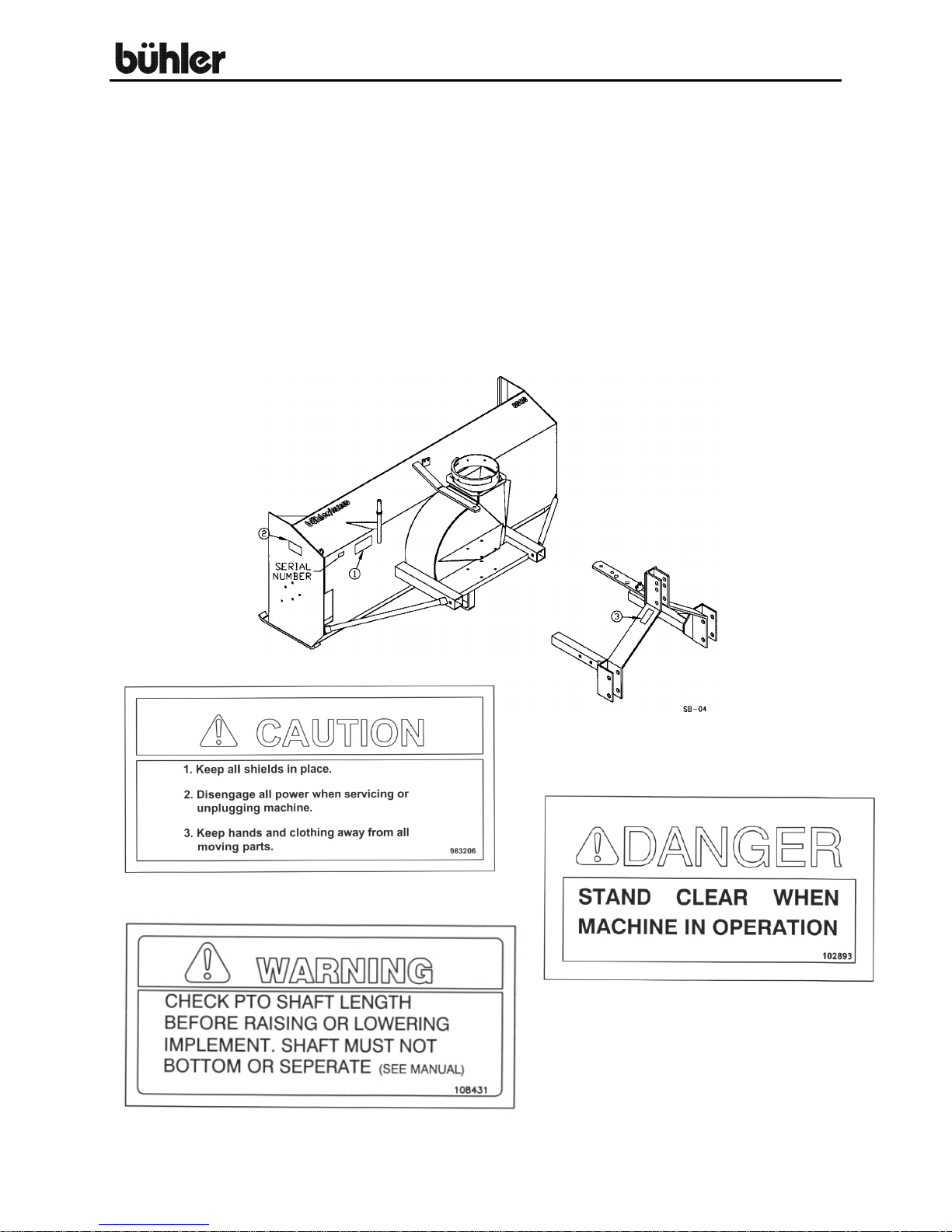
SNOWBLOWER
This manual covers the 85” model snowblower. When ordering parts, be sure to list the
serial number of your unit and blower width. The snowblower is the push type and will
mount to a tractor with a category 1 or 2 three point hitch and 540 rpm PTO. The 85"
model has a single auger and comes with a hydraulic control for the chute with a
manual control avail able as an optio n.
The auger and the blower are equipped with shear bolts to protect the machine from
damage in case a large object is picked up. Any gravel picked up in the snow will be
thrown with it and could cause serious injury. Be careful when operating the
snowblower. Do not let children play behind the tractor or in the area of the discharged
snow.
#
#2
#3
- 3 -
85” Snowblower
BASIC ASSEMBLY INSTRUCTIONS
STEP 1. Assemble the snow chute, referring to instructions under the appropriate
heading for “manual chute” or “hydraulic chute”.
STEP 2. Check the gearbox and fill to the lower level with a winter grade
transmission oil.
STEP 3. The snowblower is shipped with lower three point hitch pins for a category
2 hitch.
STEP 4. Using tape or bright colored marking pen, mark on the outer shields of the
PTO, the position where the shaft is completely pushed together and the
position where you have a 4” overlap. Watch these marks when moving
the blower through all possible operating angles to see that the PTO shaft
stays within this range.
STEP 5. With the engine on the tractor shut off, attach the PTO shaft. The tractor
end has a standard 6-spline end with a spring loaded locking collar. The
snowblower end has a clamp style yoke with a 3/8” keyway. Slide the
yoke onto the gearbox shaft with the 3/8” shaft supplied. Lock the yoke in
place with a ½” x 3” hex bolt and lock nut fitted through the groove in the
gearbox shaft. After tightening the bolt, insert and tighten the 3/8” socket
set screw supplied. CAUTION: Always check to see that
both ends of the PTO shaft are securely attached every time the
snowblower is used. This should always be done with the tractor shut off.
STEP 6. Check that the PTO shaft does not bottom or separate with the
snowblower in the extreme high and low positions. A longer optional PTO
shaft is available if the standard shaft is too short. Check for free
movement of all parts in various raised positions: particularly the PTO
shaft.
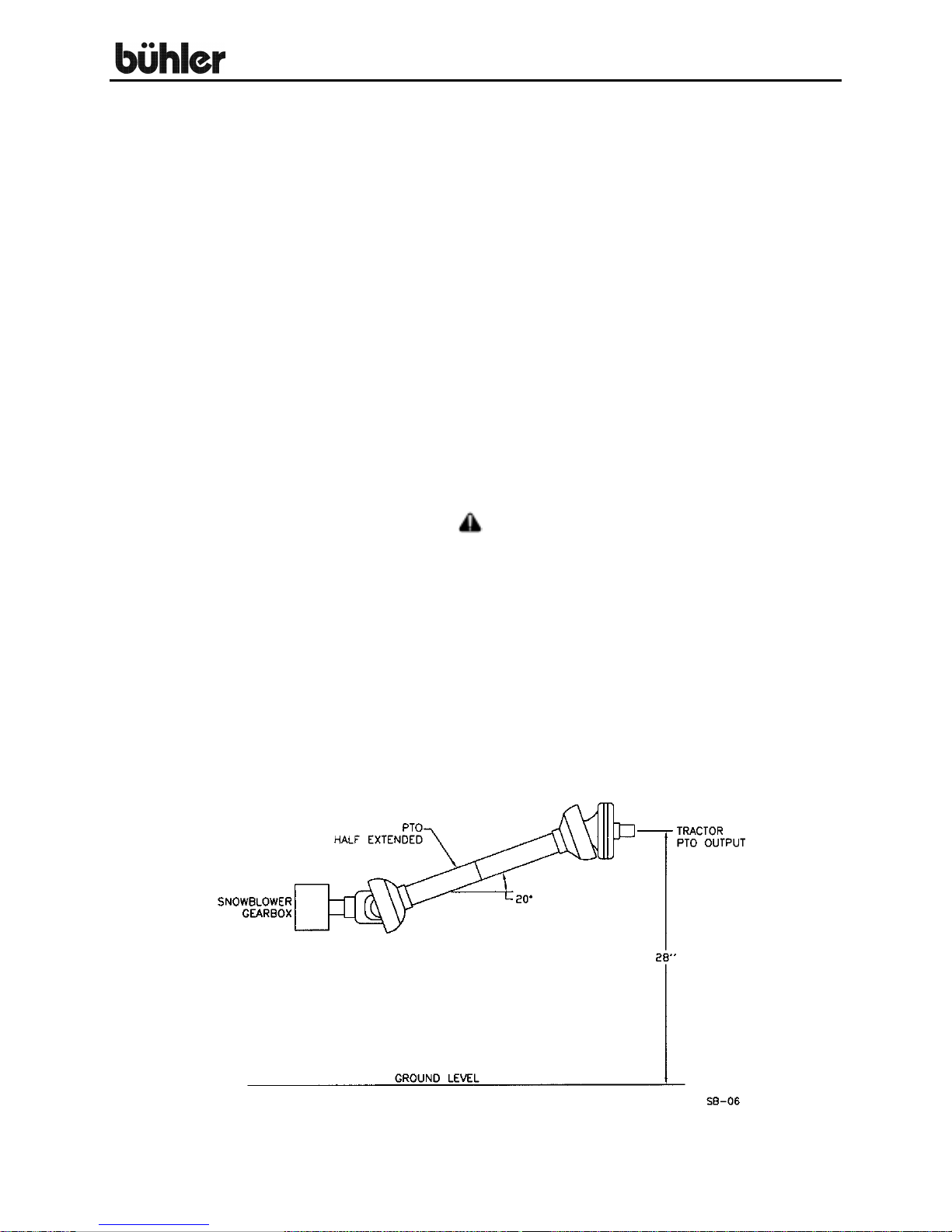
STEP 7. NOTE: Excessive u-joint wear and shear pin failure may result if the
PTO angle exceeds 20°. The drawing below gives an approximate way to
check this angle. With the PTO half extended, the tractor output should
not be over 28 inches high. Use 30 inches if the PTO is nearly fully
extended and 26 inches if it is nearly compressed.
- 4 -

85” Snowblower
OPERATING INSTRUCTIONS
1. Adjust the top link of the tractor hitch so that the snowblower is level when
resting on the ground.
2. Adjust the lower link sway chains or blocks on the tractor to restrict side
movement of the blower when operating.
3. Run the blower at low RPM to check operation.
4. The snowblower has two shear bolts to protect the tractor and blower in
case a large object enters the blower. PTO shear bolt – two 5/16" x 1"
(grade 5), auger shear bolt - 5/16" x 1 ¼” (grade 5). These bolts must be
checked every five operating hours and kept tight to prevent wear of the
bolts and bolt holes.
5. Daily check the auger bearing bolts on each side of the snowblower, the
drive sprocket bearings and the bolt holding the blower fan on the gearbox
shaft.
6. Grease the PTO and bearings every 40 hours of operation.
7. A little engine oil applied to the chain daily can double the life of the drive
chain.
8. Occasionally apply a light winter grade oil to the chute bottom ring to ease
turning.
9. Always disengage the PTO before dismounting from the tractor.
10. CAUTION: Always check to see that both ends of the PTO shaft
are securely attached as per instructions every time you are preparing to
use the snowblower.
11. Shear sprocket: The shear sprocket (#6) should be checked at the
beginning of every season to make sure it will spin freely. With time this
sprocket could corrode and seize which will not allow the shear bolt to
break if something jams in the snowblower auger. Clean to loosen if
necessary.
12. Gearbox: Use any 80-90 gear oil or multigrade with 80 minimum.
13. When replacing bearings or tightening a loose bearing collar, always
tighten collar in the direction of shaft rotation using a center punch or
similar tool.
- 5 -
 Loading...