

Page 1
Bedienungs- und Installationsanleitung
BX410013, 09/2010 Art. Nr. 90 31 150
Bühler Technologies GmbH, Harkortstr. 29, D-40880 Ratingen,
Tel. +49 (0) 21 02 / 49 89-0, Fax. +49 (0) 21 02 / 49 89-20
Internet: www.buehler-technologies.com
Email: analyse@buehler-technologies.com
1
AP000218
Installation- and Operation Instruction
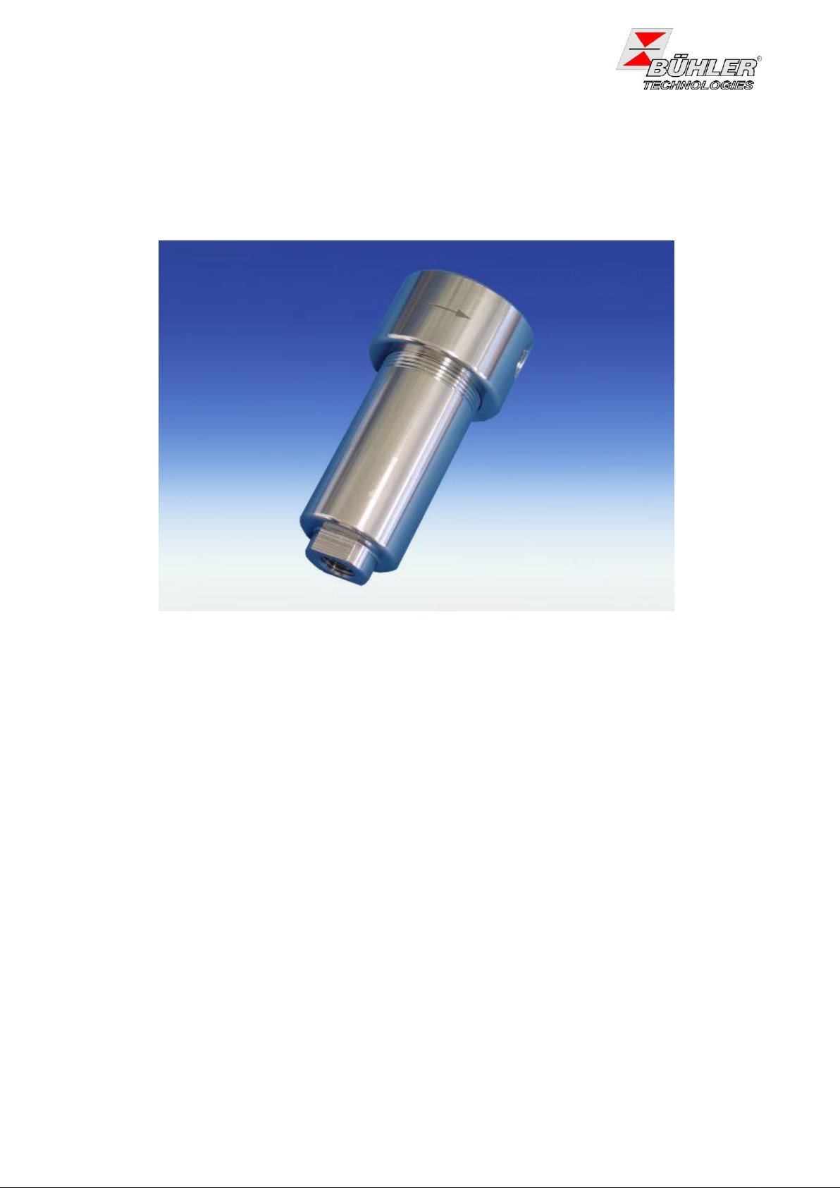
Feinfilter / fine filter AGF-VA-350
Koaleszenzfilter / coalescence filter K-AGF-VA-350
Lesen Sie die Bedienungsanleitung vor dem Gebrauch des Gerätes gründlich durch, insbesondere
die Hinweise unter Gliederungspunkt 2. Andernfalls könnten Gesundheits- oder Sachschäden
auftreten. Die Bühler Technologies GmbH haftet nicht bei eigenmächtigen Änderungen des Gerätes
oder für unsachgemäßen Gebrauch.
Read this instruction carefully prior to installation and/or use. Pay attention particularly to all
advises and safety instructions to prevent injuries. Bühler Technologies GmbH can not be held
responsible for misusing the product or unreliable function due to unauthorised modifications.
Page 2

Bedienungs- und Installationsanleitung
2
BX410013, 09/2010 Art. Nr. 90 31 150
Installation- and Operation Instruction
Feinfilter / fine filterFeinfilter: AGF-VA-350
Koaleszenzfilter / coalescence filter K-AGF-VA-350
Inhaltsverzeichnis Seite
1 Einleitung .......................................................................................................................... 3
2 Hinweise ............................................................................................................................ 3
2.1 Gefahrenhinweise ............................................................................................................................. 3
3 Produktbeschreibung ....................................................................................................... 4
3.1 Lieferumfang ..................................................................................................................................... 4
4 Transport und Lagerungsvorschriften ............................................................................ 4
5 Aufbauen und Anschließen .............................................................................................. 5
5.1 Gasanschlüsse und Bypass/Kondensatablass ................................................................................. 5
6 Wartung ................................ ................................................................ ............................. 5
6.1 Wechsel des Filterelementes ............................................................................................................ 6
6.2 Ersatzteile.......................................................................................................................................... 6
7 Instandsetzung und Entsorgung ..................................................................................... 7
7.1 Entsorgung ........................................................................................................................................ 7
8 Beigefügte Dokumente ..................................................................................................... 7
Contents Page
1 Introduction ....................................................................................................................... 8
2 Indications ......................................................................................................................... 8
2.1 Indications of Risk ............................................................................................................................. 8
3 Product Description .......................................................................................................... 9
3.1 Included Items in Delivery ................................................................................................................. 9
4 Transport and Storing Regulations ............................................................................... 10
5 Installation and Connection ........................................................................................... 10
5.1 Gas connections and bypass / condensate outlet ........................................................................... 10
6 Maintenance .................................................................................................................... 10
6.1 Replacing the Filter Element ........................................................................................................... 11
6.2 Spare Parts ..................................................................................................................................... 11
7 Repair and Disposal ....................................................................................................... 12
7.1 Disposal .......................................................................................................................................... 12
8 Attached Documents ...................................................................................................... 12
Page 3
Bedienungs- und Installationsanleitung
BX410013, 09/2010 Art. Nr. 90 31 150
3
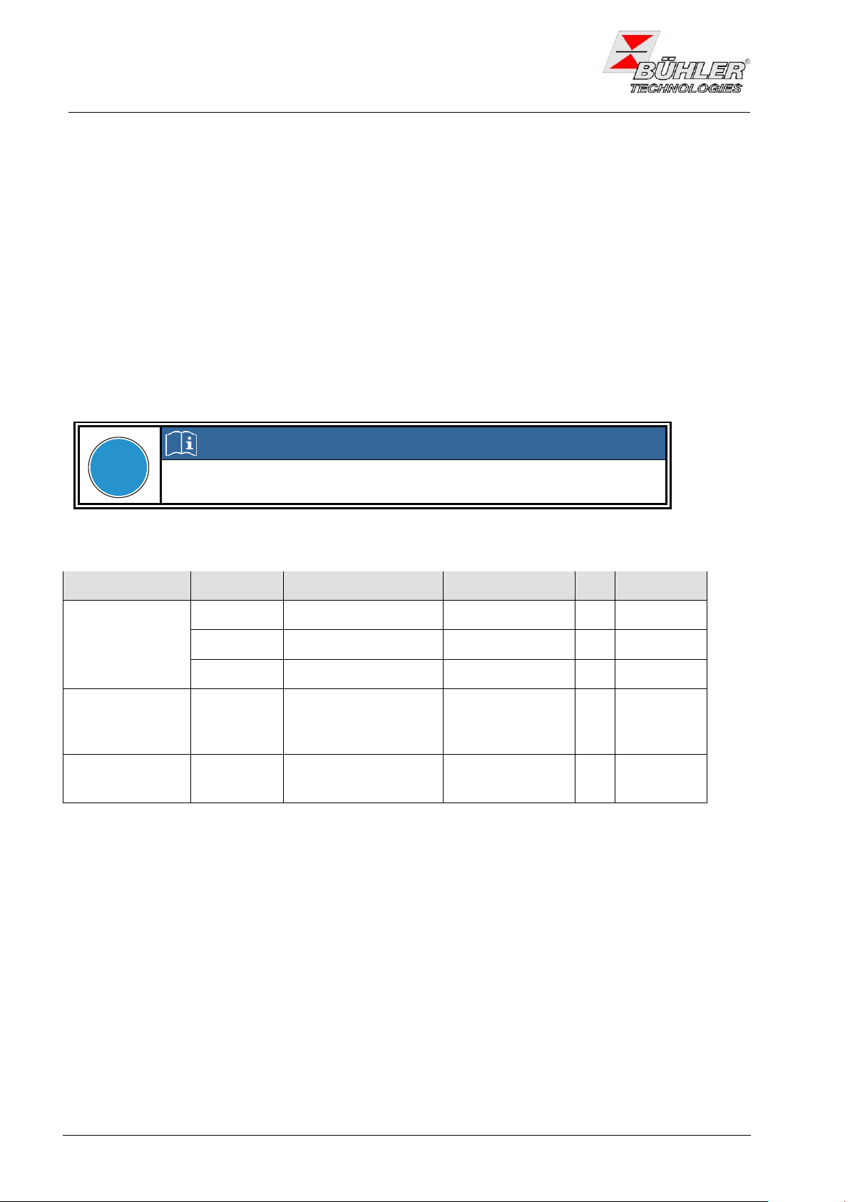
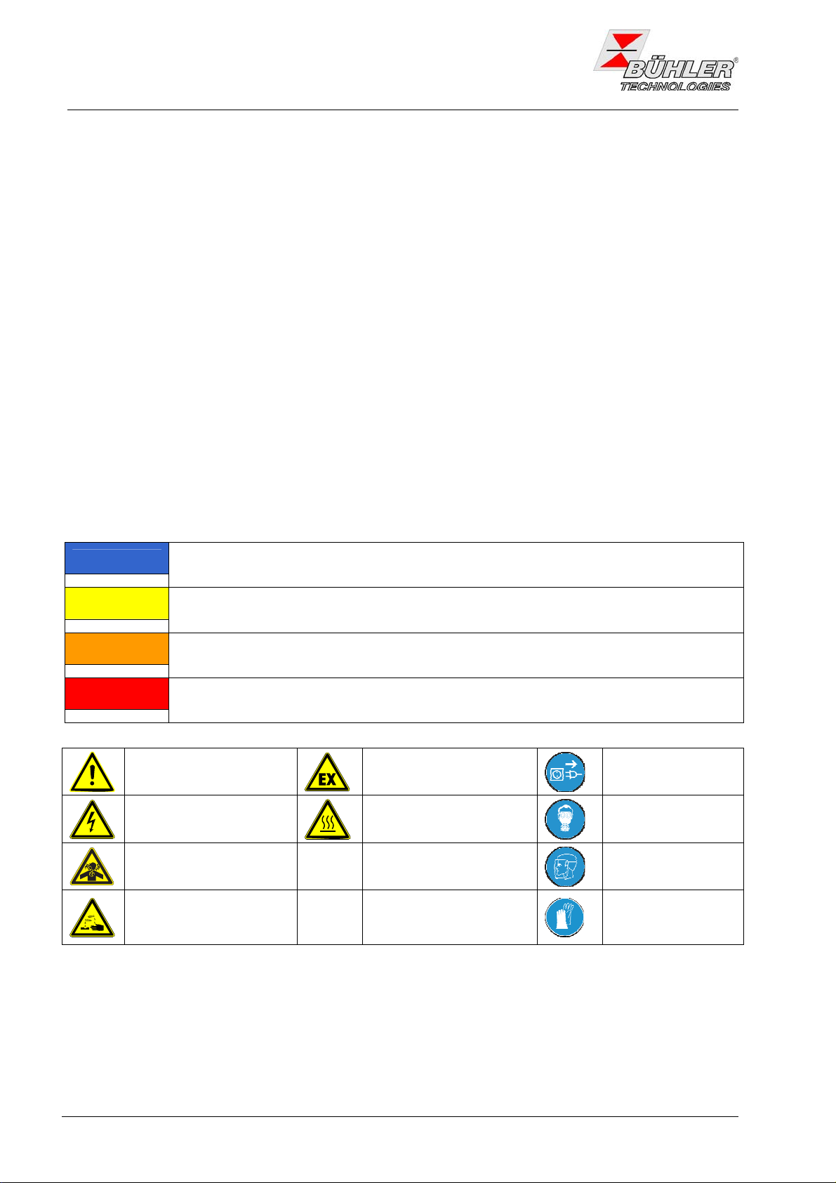
HINWEIS
Signalwort für wichtige Information zum Produkt, auf die im besonderen Maße
aufmerksam gemacht werden soll.
VORSICHT
Signalwort zur Kennzeichnung einer Gefährdung mit geringem Risiko, die zu einem Sachschaden oder leichten bis mittelschweren Körperverletzungen führen kann, wenn sie nicht
vermieden wird.
WARNUNG
Signalwort zur Kennzeichnung einer Gefährdung mit mittlerem Risiko, die möglicherweise
Tod oder schwere Körperverletzungen zur folge hat, wenn sie nicht vermieden wird.
GEFAHR
Signalwort zur Kennzeichnung einer Gefährdung mit hohem Risiko, die unmittelbar Tod
oder schwere Körperverletzung zur folge hat, wenn sie nicht vermieden wird.
Warnung vor einer
allgemeinen Gefahr
Warnung vor
explosions-gefährdeten
Bereichen
Netzstecker ziehen
Warnung vor elektrischer
Spannung
Warnung vor heißer
Oberfläche
Atemschutz tragen
Warnung vor dem Einatmen
giftiger Gase
Gesichtsschutz
tragen
Warnung vor ätzenden
Flüssigkeiten
Handschuhe
tragen
Installation- and Operation Instruction
Feinfilter / fine filterFeinfilter: AGF-VA-350
Koaleszenzfilter / coalescence filter K-AGF-VA-350
1 Einleitung
Diese Bedienungs- und Installationsanleitung gilt für Filter vom Typ AGF-VA-350 und K-AGF-VA-350.
Die Filter können innerhalb eines Gasanalysesystems zur Filterung von Messgasen verwendet werden.
Welchen Typ Sie vor sich haben, ersehen Sie aus dem Typenschild. Auf diesem finden Sie neben der
Auftragsnummer auch die Artikelnummer und Typbezeichnung. Sofern für einen Filtertyp Besonderheiten
gelten, sind diese in der Bedienungsanleitung gesondert beschrieben. Bitte beachten Sie beim Anschluss
die Kennwerte der Filter und bei Ersatzteilbestellungen die richtigen Ausführungen.
2 Hinweise
Der Einsatz der Geräte ist nur zulässig, wenn:
- das Produkt unter den in der Bedienungs- und Installationsanleitung beschriebenen Bedingungen, dem
Einsatz gemäß Typenschild und für Anwendungen, für die es vorgesehen ist, verwendet wird.
- die Service- und Reparaturarbeiten von Bühler Technologies GmbH durchgeführt werden, soweit sie
nicht in dieser Anleitung beschrieben sind.
- Originalersatzteile verwendet werden.
Diese Bedienungsanleitung ist Teil des Betriebsmittels. Der Hersteller behält sich das Recht vor, die
Leistungs-, die Spezifikations- oder die Auslegungsdaten ohne Vorankündigung zu ändern. Bewahren Sie
die Anleitung für den späteren Gebrauch auf.
2.1 Gefahrenhinweise
Begriffsbestimmungen für Warnhinweise:
Das Gerät darf nur von Fachpersonal installiert werden, das mit den Sicherheitsanforderungen und den
Risiken vertraut ist.
Beachten Sie unbedingt die für den Einbauort relevanten Sicherheitsvorschriften und allgemein gültigen
Regeln der Technik. Beugen Sie Störungen vor und vermeiden Sie dadurch Personen- und Sachschäden.
Page 4
Bedienungs- und Installationsanleitung
4
BX410013, 09/2010 Art. Nr. 90 31 150
!
GEFAHR
Giftige, ätzende Gase
Messgas kann gesundheitsgefährdend sein.
Sorgen Sie ggf. für eine sichere Ableitung des Gases.
Stellen Sie vor Beginn der Wartungsarbeiten die Gaszufuhr ab und sichern
Sie sie gegen unbeabsichtigtes Aufdrehen.
Schützen Sie sich bei der Wartung vor giftigen / ätzenden Gasen. Tragen Sie
die entsprechende Schutzausrüstung.
Installation- and Operation Instruction
Feinfilter / fine filterFeinfilter: AGF-VA-350
Koaleszenzfilter / coalescence filter K-AGF-VA-350
Der für die Anlage Verantwortliche muss sicherstellen, dass:
- Sicherheitshinweise und Betriebsanleitungen verfügbar sind und eingehalten werden,
- Unfallverhütungsvorschriften der Berufsgenossenschaften beachtet werden; in Deutschland:
„Allgemeine Vorschriften” (VBG 1) und „Elektrische Anlagen und Betriebsmittel (VBG 4)”,
- die zulässigen Daten und Einsatzbedingungen eingehalten werden,
- Schutzeinrichtungen verwendet werden und vorgeschriebene Wartungsarbeiten durchgeführt werden,
- bei der Entsorgung die gesetzlichen Regelungen beachtet werden.
Wartung, Reparatur:
- Reparaturen an den Betriebsmitteln dürfen nur von Bühler autorisiertem Personal ausgeführt werden.
- Nur Umbau-, Wartungs- oder Montagearbeiten ausführen, die in dieser Bedienungs- und
Installationsanleitung beschrieben sind.
- Nur Original-Ersatzteile verwenden.
Bei Durchführung von Wartungsarbeiten jeglicher Art müssen die relevanten Sicherheits- und
Betriebsbestimmungen beachtet werden.
3 Produktbeschreibung
AGF-VA-350-T Filter aus Edelstahl mit Dichtung Viton / FEP ummantelt
K-AGF-VA-350-T Koaleszenzfilter aus Edelstahl mit Dichtung Viton / FEP ummantelt
Der maximal zulässige Druck beträgt 270 bar abs. bei Temperaturen bis 150°C.
3.1 Lieferumfang
1. Feinfilter AGF-VA-350 oder Koaleszenzfilter K-AGF-VA-350
2. Bedienungsanleitung BX410013
4 Transport und Lagerungsvorschriften
Die Produkte nur in der Originalverpackung oder einem geeigneten Ersatz transportieren.
Bei längerer Nichtbenutzung sind die Betriebsmittel gegen Feuchtigkeit und Wärme zu schützen.
Sie müssen in einem überdachten, trockenen und staubfreien Raum bei einer Temperatur von –20°C bis
+60°C aufbewahrt werden.
Page 5
Bedienungs- und Installationsanleitung
BX410013, 09/2010 Art. Nr. 90 31 150
5
GEFAHR
Giftige, ätzende Gase
Gas im Filter, Kondensat und auch verbrauchte Filterelemente können giftig
oder ätzend sein.
Schalten Sie vor Beginn der Wartungsarbeiten die Gaszufuhr ab und spülen
Sie die Gasleitungen und den Filter ggf. mit Luft.
Bitte sorgen Sie ggf. für eine sichere Ableitung des Gases.
Schützen Sie sich bei der Wartung vor giftigen / ätzenden Gasen. Tragen Sie
die entsprechende Schutzausrüstung.
Beschädigte Teile oder O-Ringe nicht wieder verwenden.
Installation- and Operation Instruction
Feinfilter / fine filterFeinfilter: AGF-VA-350
Koaleszenzfilter / coalescence filter K-AGF-VA-350
5 Aufbauen und Anschließen
Der Filter soll so eingebaut werden, dass ein Wechsel des Filterelements noch möglich ist (siehe unter 6.).
Wenn der Filter aus einer Kontur herausragt, beachten Sie bitte, dass die Gefahr einer Beschädigung
besteht.
Der Abstand für die Befestigungslöcher (für Schrauben M6) beträgt 25 mm.
5.1 Gasanschlüsse und Bypass/Kondensatablass
Die Anschlüsse sind mittels geeigneter Verschraubungen (Gasanschlüsse rechts und links und
Bypass/Kondensatablass unten: NPT 1/4) und Dichtmittel sorgfältig und fachgerecht anzuschließen. Wenn
der Bypass/Kondensatablass nicht genutzt wird, ist das Gewinde mit einem Verschlussstopfen zu versehen,
der als Zubehör erhältlich ist (siehe Datenblatt). Die Durchflussrichtung ist auf dem Filterkopf mit einem
Pfeil gekennzeichnet. Der Filter kann auf dem Montagewinkel gedreht werden, um die Seite von Ein- und
Ausgang zu tauschen.
6 Wartung
Das Gerät darf nur von Fachpersonal installiert und gewartet werden, das mit den Sicherheitsanforderungen und den Risiken vertraut ist.
- Das Gerät darf nicht außerhalb seiner Spezifikationen betrieben werden.
- Reparaturen an den Betriebsmitteln dürfen nur von Bühler autorisiertem Personal ausgeführt werden.
- Führen Sie nur Umbau-, Wartungs- oder Montagearbeiten aus, die in dieser Bedienungs- und
Installationsanleitung beschrieben sind.
- Verwenden Sie nur Original-Ersatzteile.
- Beachten Sie bei der Durchführung von Wartungsarbeiten jeglicher Art die relevanten Sicherheits- und
Betriebsbestimmungen.
Page 6
Bedienungs- und Installationsanleitung
6
BX410013, 09/2010 Art. Nr. 90 31 150
!
HINWEIS
Beachten Sie bei der Entsorgung der Filterelemente die gesetzlichen
Regelungen.
Filtertyp
Element
Filtereinheit
Temperatur max.
VE
Artikel-Nr.
AGF-VA-350
GF2
2 m
150°C
1
41 35 G002
GF5
5 m
150°C
1
41 35 G005
GF10
10 m
150°C
1
41 35 G010
K-AGF-VA-350
Koaleszenz
Abscheidegrad
>99,99% Luft (0,1
m)
150°C
1
49 32 002
O-Ring Viton /
FEP ummantelt
1
90 09 297
Installation- and Operation Instruction
Feinfilter / fine filterFeinfilter: AGF-VA-350
Koaleszenzfilter / coalescence filter K-AGF-VA-350
6.1 Wechsel des Filterelementes
Vorgehensweise:
Anlage druckfrei setzen u. Filter vor dem Öffnen mit Luft spülen
Filtertopf im Uhrzeigersinn vom Filterkopf abschrauben.
Stützrohr mit Filterelement vom Filterkopf abschrauben.
Filterelement vom Stützrohr abziehen uns neues Element aufschieben.
Stützrohr mit Filterelement handfest in den Filterkopf einschrauben. Die Selbstabdichtung erfolgt
über den leichten stirnseitigen Andruck des Filterelements. Eine zu starke Flächenpressung ist zu
vermeiden.
O-Ring des Filtertopfes überprüfen und bei Beschädigung gegen einen neuen austauschen.
Filtertopf handfest mit dem Filterkopf verschrauben.
Dichtigkeit prüfen.
6.2 Ersatzteile
Page 7

Bedienungs- und Installationsanleitung
BX410013, 09/2010 Art. Nr. 90 31 150
7
Installation- and Operation Instruction
Feinfilter / fine filterFeinfilter: AGF-VA-350
Koaleszenzfilter / coalescence filter K-AGF-VA-350
7 Instandsetzung und Entsorgung
Sollte ein Fehler beim Betrieb auftreten, wenden Sie sich bitte an unseren Service
Tel.: +49-(0)2102-498955 oder Ihre zuständige Vertretung.
Ist nach Beseitigung eventueller Störungen und nach Einschalten der Netzspannung die korrekte Funktion
nicht gegeben, muss das Gerät durch den Hersteller überprüft werden. Bitte senden Sie das Gerät zu
diesem Zweck in geeigneter Verpackung an:
Bühler Technologies GmbH
- Reparatur/Service Harkortstraße 29
40880 Ratingen
Deutschland
Bringen Sie zusätzlich die Dekontaminierungserklärung ausgefüllt und unterschrieben an der Verpackung
an. Ansonsten ist eine Bearbeitung Ihres Reparaturauftrages nicht möglich! Das Formular kann per E-Mail
angefordert werden: service@buehler-technologies.com.
7.1 Entsorgung
Bei der Entsorgung sind die gesetzlichen Vorschriften, insbesondere für die Entsorgung von elektronischen
Bauteilen, zu beachten.
8 Beigefügte Dokumente
- Datenblatt DD 4100013
- Datenblatt DD 4100017
- Dekontaminierungserklärung
Page 8
Bedienungs- und Installationsanleitung
Installation- and Operation Instruction
Feinfilter / fine filter AGF-VA-350
Koaleszenzfilter / coalescence filter K-AGF-VA-350
1 Introduction
This installation and operation manual describes filter models AGF-VA-350 and K-AGF-VA-35.
The filters are designed for use in sample gas systems for filtering sample gas probes.
The exact type is indicated on the type plate. Here also order number, part number, and type designation
are indicated. If there are special instructions for a certain type, they are described in the manual. Regard
the specific limits of the filter. Please only order the spare parts matching the filter type.
2 Indications
Operation of the device is only valid if
- the product is used under the conditions described in the installation- and operation instruction.
- service and repair is carried out by Bühler Technologies GmbH (unless described in this manual).
- only original spare parts are used.
This manual is part of the equipment. The manufacturer keeps the right to modify specifications without
advanced notice. Keep this manual for later use
.
2.1 Indications of Risk
Definitions for warnings:
NOTE
CAUTION
WARNING
DANGER
Warning against
hazardous situation
Warning against
electrical voltage
Warning against
respiration of toxic gases
Warning against acid
and corrosive
substances
Signal word for important information to the product.
Signal word for a hazardous situation with low risk, resulting in damaged to the device or
the property or minor or medium injuries if not avoided.
Signal word for a hazardous situation with medium risk, possibly resulting in severe
injuries or death if not avoided.
Signal word for an imminent danger with high risk, resulting in severe injuries or death if
not avoided.
Warning against possible
explosive atmospheres
Warning against hot
surface
disconnect from
mains
wear respirator
wear face
protection
wear gloves
Installation of the device shall be performed by trained staff only, familiar with the safety requirements and
risks. Check all relevant safety regulations and technical indications for the specific installation place.
Prevent failures and protect persons against injuries and the device against damage.
8
BX410013, 09/2010 Art. Nr. 90 31 150
Page 9

Bedienungs- und Installationsanleitung
BX410013, 09/2010 Art. Nr. 90 31 150
9
DANGER
Toxic and corrosive gases
Sample gas can be hazardous.
Take care that the gas is exhausted in a place where no persons are in
danger.
Before maintenance turn off the gas supply and make sure that it cannot be
turned on unintentionally.
Protect yourself during maintenance against toxic / corrosive gases. Use
gloves, respirator and face protector under certain circumstances.
Installation- and Operation Instruction
Feinfilter / fine filterFeinfilter: AGF-VA-350
Koaleszenzfilter / coalescence filter K-AGF-VA-350
The person responsible for the system must secure that:
- safety and operation instructions are accessible and followed,
- local safety regulations and standards are obeyed,
- performance data and installation specifications are regarded,
- safety devices are installed and recommended maintenance is performed,
- national regulations for disposal of electrical equipment are obeyed.
Maintenance and repair
- Repairs on the device must be carried out by Bühler authorized persons only.
- Only perform modifications, maintenance or mounting described in this manual.
- Only use original spare parts.
During maintenance regard all safety regulations and internal operation instructions.
3 Product Description
AGF-VA-350-T Filter made of stainless steel with Viton seal / FEP covered
K-AGF-VA-350-T stainless steel coalescence filter with Viton seal / FEP covered
The maximum pressure is 270 bar abs. for temperatures up to 150°C.
3.1 Included Items in Delivery
1. Fine filter AGF-VA-350 or coalescence filter K-AGF-VA-350
2. Installation and Operation Instruction BX410013
Page 10

Bedienungs- und Installationsanleitung
10
BX410013, 09/2010 Art. Nr. 90 31 150
DANGER
Toxic, corrosive gases
The gas inside the filter, condensate and used filter elements may be caustic
or corrosive.
Before maintenance turn off the gas supply and make sure that it cannot be
turned on unintentionally. Rinse filter with air before opening!
Please exhaust sample gas to a safe place.
Protect yourself against toxic / corrosive gas during maintenance. Use gloves,
respirator and face protector under certain circumstances.
Installation- and Operation Instruction
Feinfilter / fine filterFeinfilter: AGF-VA-350
Koaleszenzfilter / coalescence filter K-AGF-VA-350
4 Transport and Storing Regulations
The equipment should be only transported in the original case or in appropriate packing.
Protect the equipment against heat and humidity.
The filter must be stored in roofed, dry, and dust free room. Temperature should be between –20°C and
+60°C (-4°F to 320°F).
5 Installation and Connection
The filter should be mounted in such a way to assure easy replacing of the filter element (see 6. for the
procedure). Be aware that the filter may be damaged if is mounted outside a housings shape. In this case
take precautions against damage.
Mounting is done by two screws M6 in a distance of 25 mm (0.98 in)
5.1 Gas connections and bypass / condensate outlet
The connections (NPT 1/4 fittings for gas inlets and outlets on the left and right and bypass / condensate
outlet at the bottom) have to be made correctly and with care using sealant. If the bypass / condensate
outlet is not used, close the fitting with a sealing plug, available as accessory (see data sheet). An arrow on
the filter head indicates the flow direction. The filter can be rotated on the mounting bracket to change inlet
and outlet.
6 Maintenance
Installation and maintenance of the device shall be performed by trained staff only, familiar with the safety
requirements and risks.
- The device must be operated within its specifications.
- All repairs must be carried out by Bühler authorised personnel only.
- Only perform modifications, servicing or mounting described in this manual.
- Only use original spare parts.
- Regard all relevant safety regulations and internal operating instructions during maintenance.
Page 11

Bedienungs- und Installationsanleitung
BX410013, 09/2010 Art. Nr. 90 31 150
11
!
NOTE
Regard Local Regulations for disposal of used filter elements.
Filter type
Element
Filter retention
Temperature max.
pcs
Part no.
AGF-VA-350
GF2
2 m
150°C
1
41 35 G002
GF5
5 m
150°C
1
41 35 G005
GF10
10 m
150°C
1
41 35 G010
K-AGF-VA-350
coalescence
Filtration efficiency
>99,99% air (0,1 m)
150°C
1
49 32 002
O-ring Viton /
FEP covered
1
90 09 297
Installation- and Operation Instruction
Feinfilter / fine filterFeinfilter: AGF-VA-350
Koaleszenzfilter / coalescence filter K-AGF-VA-350
6.1 Replacing the Filter Element
Procedure:
Before opening the filter release the pressure and rinse filter with air.
Turn the filter housing counter clock wise to unscrew it from the filter head.
Unscrew the supporting tube carrying the filter element.
Remove the filter element from the supporting tube and replace it by a new one.
Refit the supporting tube to the filter head by hand. The filter element is self-sealing due to a slight
surface pressure. Avoid to high surface pressure
Check the O-ring at the filter case and replace it in case of damage or defects. Screw the filter case
to the filter head by hand.
Check leak-tightness.
6.2 Spare Parts
Page 12

Bedienungs- und Installationsanleitung
12
BX410013, 09/2010 Art. Nr. 90 31 150
Installation- and Operation Instruction
Feinfilter / fine filterFeinfilter: AGF-VA-350
Koaleszenzfilter / coalescence filter K-AGF-VA-350
7 Repair and Disposal
If the device shows irregularities
call +49(0)2102-498955 or your local agent.
If the device doesn’t work correctly after elimination of failures and turning power on, the device must be
checked by the manufacturer. Please ship the device with suitable packing to
Bühler Technologies GmbH
- Service Harkortstraße 29
40880 Ratingen
Germany
In Addition, attach the filled in and signed Declaration of Decontamination status to the packing. Otherwise,
your repair order cannot be processed! The form can be requested by e-mail to service@buehler-
technologies.com.
7.1 Disposal
Regard the local regulations for disposal of electric and electronic equipment.
8 Attached Documents
- Datasheet DE/DA 410013
- Datasheet DE/DA 410017
- Declaration of Contamination status
Page 13

Feinfilter
AGF - VA - 350
®
In der allgemeinen Gas- und Flüssigkeitsfiltration,
besonders aber in Analysesystemen, werden kompakte, einfach zu bedienende Filter benötigt. Das
Filtergehäuse erfüllt die Anforderungen dieser Werkzeuge
Einsatzfelder in besonderem Maße.
§ Sehr einfaches und schnelles
Wechseln der Filterelemente ohne
§ Geringes Totvolumen
Der Montagewinkel kann um 180° gedreht montiert
werden und gestattet so die Wandmontage des
Filtergehäuses in der gewünschten Durchflussrichtung.
Für unterschiedliche Einsatzparameter stehen
passende Filterelemente zur Auswahl. Elemente und
Gehäuse sind so aufeinander abgestimmt, dass
geringe Totvolumina entstehen.
DD 41 0013
09/2008
Tel.: + 49 (0) 2102 / 49 89-0 Fax: + 49 (0) 2102 / 49 89-20
§ Variable Wandmontage über einen
Montagewinkel
§ Möglichkeit der (autom.) Kondensatableitung durch Anschlussgewinde
(NPT 1/4) in der Filterglocke
Bühler Technologies GmbH
D - 40880 Ratingen, Harkortstr. 29
Internet: www.buehler-technologies.com
e-mail: analyse@buehler-technologies.com
Page 14

Abmessungen (mm)
80
ø7
X
5
0 9
00 1
A
Bypass
NPT 1/4
Aus
NPT 1/4
1 30
10
35
60
Ein
NPT 1/4
153
169
0
Technische Daten Material
Temperatur max. 150 °C
Druck max. 350 bar
Totvolumen mit Filterelement 18 ml
Gewicht ca. 0,8 kg
Gehäuse komplett 1.4404 (SS 316L)
Filterelemente siehe Tabelle
Dichtungsmaterial Viton FEP ummantelt
55
Ø50
Ø36
Bestellhinweise
Filter
Art. Nr. Typ Material
41 35 999 AGF-VA-350-T, Leergehäuse Dichtung Viton, FEP ummantelt
41 35 9993 Montagewinkel 1.4301 (SS 304)
90 08 802 Stopfen NPT 1/4 1.4401 (SS 316)
Filterelemente
Art. Nr. Type Material Filterfeinheit max. Temperatur
41 35 G002 GF2 Glasfaser / Epoxidharz 2 µm 150 °C
41 35 G005 GF5 Glasfaser / Epoxidharz 5 µm 150 °C
41 35 G010 GF10 Glasfaser / Epoxidharz 10 µm 150 °C
Technische Änderungen vorbehalten
Page 15

Sample Gas Filter
AGF - VA - 350
®
Sample gas streams must be conditioned to provide § Easy filter change without tools
particulate and moisture-free gas to the analyser.
§ Low dead volume
The AGF-VA-350 provides fine filtration and easy replacement of the filter media without the use of tools. This means
the filter media can be changed in a matter of seconds.
§ Variable attachment configurations
§ Optional condensate drain
The mounting bracket can be installed at an angle of 180°
making the mounting of the filter independent from the flow
direction chosen.
A choice of filter media is available to meet any specific
application need. The filter and housing provide a small dead
volume.
Bühler Technologies GmbH
DE 41 0013
09/2008
Tel.: + 49 (0) 2102 / 49 89-0 Fax: + 49 (0) 2102 / 49 89-20
D - 40880 Ratingen, Harkortstr. 29
Internet: www.buehler-technologies.com
e-mail: analyse@buehler-technologies.com
Page 16

Dimensions in mm
80
ø7
X
5
0 9
00 1
A
Bypass
NPT 1/4
OUT
NPT 1/4
1 30
10
35
60
IN
NPT 1/4
153
169
0
Technical Data Material
Temperature max. 150 °C
Pressure max. 350 bar
Dead volume 18 ml with filter element
Weight approx. 0.8 kg
Housing 1.4404 (SS 316L)
Filter elements See table below
Seal Viton FEP covered
55
Ø50
Ø36
Please indicate with order
Filter
Part no. Type Material
41 35 999 AGF-VA-350-T, housing Seal Viton FEP covered
41 35 9993 Mounting bracket 1.4301 (SS 304)
90 08 802 Plug NPT 1/4 1.4401 (SS 316)
Filter elements
Part no. Type Material Pore size max. Temperature
41 35 G002 GF2 glass fibre / epoxy resin 2 µm 150 °C
41 35 G005 GF5 glass fibre / epoxy resin 5 µm 150 °C
41 35 G010 G10 glass fibre / epoxy resin 10 µm 150 °C
we reserve the right to amend specification
Page 17

Sample Gas Filter
AGF - VA - 350
Sample gas streams must be conditioned to provide § Easy filter change without tools
particulate and moisture-free gas to the analyser.
§ Low dead volume
The AGF-VA-350 provides fine filtration and easy replacement of the filter media without the use of tools. This means
the filter media can be changed in a matter of seconds.
§ Variable attachment configurations
§ Optional condensate drain
The mounting bracket can be installed at an angle of 180°
making the mounting of the filter independent from the flow
direction chosen.
A choice of filter media is available to meet any specific
application need. The filter and housing provide a small dead
volume.
Buhler Technologies LLC
Internet: www.buhler-technologies.com
e-mail: r.brown@buhler-technologies.com
DA 41 0013
09/2008
1030 West Hamlin Road, Rochester Hills, MI 48309
Phone: 248.652.1546 Fax: 248.652.1598
Page 18

Dimensions (inch)
3.15
X
9
5
00
0 1
A
Bypass
NPT 1/4
ø0.28
OUT
NPT 1/4
6
4 0.
IN
NPT 1/4
0
0.39
1.38
2.36
6.02
6.65
Technical Data Material
Temperature max. 302 °F
Pressure max. 5076 psi
Dead volume 18 ml with filter element
Weight approx. 1.76 lb
Housing 1.4404 (SS 316L)
Filter elements See table below
Seal Viton FEP covered
2.17
Ø1.97
Ø1.42
Please indicate with order
Filter
Part no. Type Material
41 35 999 AGF-VA-350-T, housing Seal Viton FEP covered
41 35 9993 Mounting bracket 1.4301 (SS 304)
90 08 802 Plug NPT 1/4 1.4401 (SS 316)
Filter elements
Part no. Type Material Pore size max. Temperature
41 35 G002 GF2 glass fibre / epoxy resin 2 µm 302°F
41 35 G005 GF5 glass fibre / epoxy resin 5 µm 302°F
41 35 G010 G10 glass fibre / epoxy resin 10 µm 302°F
we reserve the right to amend specification
Page 19

Koaleszenzfilter
K - AGF - VA - 350
®
In Gasaufbereitungssystemen der Analysentechnik ist
häufig die Entfernung von Aerosolen aus dem Gasstrom
erforderlich. Hierbei handelt es sich um schwebende
Flüssigkeitströpfchen (Aerosole), die in einer speziell Werkzeuge
aufgebauten Filtermatrix abgeschieden werden. Dies erfolgt
mit hohem Wirkungsgrad dadurch, dass der Gasstrom von
innen nach außen durch die Filtermatrix geführt wird. Dabei
werden die kleinen Flüssigkeitströpfchen soweit koaliert, bis
sich große Tropfen gebildet haben, die infolge der Schwerkraft im Filterelement absinken und sich im Boden der
Filterglocke ansammeln bzw. durch die Ablaßöffnung
abfließen. Die Lebensdauer des Filterelementes hängt im
wesentlichen davon ab, ob der Gasstrom noch zusätzlich
mit Feststoffpartikeln belastet ist. Diese werden ebenfalls in
der Filtermatrix abgeschieden und reduzieren dadurch die
Standzeit. Wenn der Gasstrom frei von Partikeln ist, bleibt
die Funktion des Filterelementes nahezu unbegrenzt
erhalten. Das Ableiten des gesammelten Kondensates
erfolgt bei druckbeaufschlagten Systemen über automatische Kondensatentleerungsventile oder bei Unterdruck im
System über Sammelgefäße und/oder Schlauchpumpen.
DD 41 0017
12/2010
Tel.: + 49 (0) 2102 / 49 89-0 Fax: + 49 (0) 2102 / 49 89-20
§ Sehr einfaches und schnelles
Wechseln der Filterelemente ohne
§ Geringes Totvolumen
§ Variable Wandmontage über einen
Montagewinkel
§ Kondensatableitung durch
Anschlussgewinde
(NPT 1/4) in der Filterglocke
Bühler Technologies GmbH
D - 40880 Ratingen, Harkortstr. 29
Internet: www.buehler-technologies.com
e-mail: analyse@buehler-technologies.com
Page 20

Abmessungen (mm)
80
ø7
X
5
0 9
00 1
A
Bypass
NPT 1/4
Aus
NPT 1/4
1 30
10
35
60
Ein
NPT 1/4
153
169
0
Technische Daten Material
Temperatur max. 150 °C
Druck max. 350 bar
Totvolumen mit Filterelement 18 ml
Gewicht ca. 0,8 kg
Gehäuse komplett 1.4404 (SS 316L)
Filterelement siehe Tabelle
Dichtungsmaterial Viton FEP ummantelt
55
Ø50
Ø36
Bestellhinweise
Filter
Art. Nr. Typ Material
41 35 099 K-AGF-VA-350-T, Leergehäuse Dichtung Viton, FEP ummantelt
41 35 9993 Montagewinkel 1.4301 (SS 304)
90 08 802 Stopfen NPT 1/4 1.4401 (SS 316)
Filterelement
Art. Nr. Type Filtereinsatz Material Filterfläche VE Stück
49 32 002 12-57-C Hülse Borosilikatfaser 28 cm² 1
Technische Änderungen vorbehalten
Page 21

Sample Gas Coalescing Filter
K - AGF - VA - 350
®
The removal of aerosols from sample gas streams is a
requirement in many applications. To meet this need, the § Easy filter change without tools
Bühler Model K-AGF-VA-350 filter makes use of a coalesc-
§ Low dead volume ing element made of borosilicate fibers. The gas stream
passes through the element from inside to outside. The
aerosols are caught in the matrix forming steadily growing
droplets which eventually drop into the bowl as a liquid. The
liquid collected in the bowl is drained off by either by a
condensate drain or peristaltic pump.
The lifetime of the element depends on the concentration of
particulate matter in the gas stream. With upstream
particulate filtration, the coalescing filter life is almost
unlimited.
DE 41 0017
12/2010
Tel.: + 49 (0) 2102 / 49 89-0 Fax: + 49 (0) 2102 / 49 89-20
§ Variable attachment configurations
§ Condensate drain
Bühler Technologies GmbH
D - 40880 Ratingen, Harkortstr. 29
Internet: www.buehler-technologies.com
e-mail: analyse@buehler-technologies.com
Page 22

Dimensions in mm
80
ø7
X
5
0 9
00 1
A
Bypass
NPT 1/4
OUT
NPT 1/4
1 30
10
35
60
IN
NPT 1/4
153
169
0
Technical Data Material
Temperature max. 150 °C
Pressure max. 350 bar
Dead volume 18 ml with filter element
Weight approx. 0.8 kg
Housing 1.4404 (SS 316L)
Filter element See table below
Seal Viton FEP covered
55
Ø50
Ø36
Please indicate with order
Filter
Part no. Type Material
41 35 099 K-AGF-VA-350-T, housing Seal Viton FEP covered
41 35 9993 Mounting bracket 1.4301 (SS 304)
90 08 802 Plug NPT 1/4 1.4401 (SS 316)
Filter element
Part no. Type Filter element Material Surface area Package
49 32 002 12-57-C husk borosilicat 28 cm² 1 pc.
we reserve the right to amend specification
Page 23

Sample Gas Coalescing Filter
K - AGF - VA - 350
The removal of aerosols from sample gas streams is a § Easy filter change without tools
requirement in many applications. To meet this need, the
§ Low dead volume Bühler Model K-AGF-VA-350 filter makes use of a coalesc-
ing element made of borosilicate fibers. The gas stream
passes through the element from inside to outside. The
aerosols are caught in the matrix forming steadily growing
droplets which eventually drop into the bowl as a liquid. The
liquid collected in the bowl is drained off by either by a
condensate drain or peristaltic pump.
The lifetime of the element depends on the concentration of
particulate matter in the gas stream. With upstream
particulate filtration, the coalescing filter life is almost
unlimited.
DA 41 0017
12/2010
1030 West Hamlin Road, Rochester Hills, MI 48309
§ Variable attachment configurations
§ Condensate drain
Buhler Technologies LLC
Phone: 248.652.1546 Fax: 248.652.1598
Internet: www.buhlertech.com
e-mail: sales@buhlertech.com
Page 24

Dimensions (inch)
3.15
X
9
5
00
0 1
A
Bypass
NPT 1/4
ø0.28
OUT
NPT 1/4
6
4 0.
IN
NPT 1/4
0
0.39
1.38
2.36
6.02
6.65
Technical Data Material
Temperature max. 302 °F
Pressure max. 5076 psi
Dead volume 18 ml with filter element
Weight approx. 1.76 lb
Housing 1.4404 (SS 316L)
Filter element See table below
Seal Viton FEP covered
2.17
Ø1.97
Ø1.42
Please indicate with order
Filter
Part no. Type Material
41 35 099 K-AGF-VA-350-T, housing Seal Viton FEP covered
41 35 9993 Mounting bracket 1.4301 (SS 304)
90 08 802 Plug NPT 1/4 1.4401 (SS 316)
Filter element
Part no. Type Filter element Material Surface area Package
49 32 002 12-57-C husk borosilicate 4.3 in² 1 pc.
we reserve the right to amend specification
Page 25

Dekontaminierungserklärung
Declaration of Contamination status
Gültig ab / valid since: 2011/05/01 Revision 0 ersetzt Rev. / replaces Rev ---
Die gesetzlichen Vorschriften schreiben vor, dass Sie uns die Dekontaminierungserklärung ausgefüllt und unterschrieben
zurück zu senden haben. Die Angaben dienen zum Schutz unserer Mitarbeiter. Bringen Sie die Bescheinigung an der
Verpackung an. Ansonsten ist eine Bearbeitung Ihres Reparaturauftrages nicht möglich!
Legal regulations prescribe that you have to fill in and sign the Declaration of Contamination status and send it back. This
information is used to protect our employees. Please attach the declaration to the packing. Otherwise, your repair
order cannot be processed.
Gerät /
Device:
Rücksendegrund /
Reason for return:
[ ] Ich bestätige hiermit, dass das oben spezifizierte Gerät ordnungsgemäß gereinigt und dekontaminiert wurde
und keinerlei Gefahren im Umgang mit dem Produkt bestehen.
I herewith declare that the device as specified above has been properly cleaned and decontaminated and that
there are no risks present when dealing with the device.
Ansonsten ist die mögliche Gefährdung genauer zu beschreiben / In other cases, please describe the hazards in
detail:
Aggregatzustand (bitte ankreuzen) / Condition of aggregation (please check):
Flüssig / Liquid Fest / Solid Pulvrig / Powdery Gasförmig / Gaseous
Folgende Warnhinweise sind zu beachten (bitte ankreuzen) / The following safety advices must be obeyed (please
check):
Serien-Nr. /
Serial no. :
Explosiv
Explosives
Komprimierte Gase
Gas under pressure
Bitte legen Sie ein aktuelles Datenblatt des Gefahrenstoffes bei / Please include the current material safety data sheet
of the hazardous material!
Angaben zum Absender / Information about the dispatcher:
Firma / Company: Anschrift / Address:
Ansprechpartner /
Contact person:
Abteilung / Division: E-Mail:
Tel. / Phone: Fax:
Ort, Datum /
Location, date:
Giftig / Tödlich
Acute toxicity
Gesundheitsgefährdend
Irritant toxicity
Unterschrift /
Entzündliche Stoffe
Flammable
Gesundheitsschädlich
Health hazard
Stempel
Signature / Stamp:
Brandfördernd
Oxidizing
Umweltgefährdend
Environmental hazard
Bühler Technologies GmbH
Tel.: + 49 (0) 2102 / 4989-0 Fax: + 49 (0) 2102 / 4989-20
D - 40880 Ratingen, Harkortstr. 29
e-mail: service@buehler-technologies.com
Internet: www.buehler-technologies.com
 Loading...