

Page 1

INTRODUCTION
1.1 AirStation Versatile Access Point
(WLMR-L11G)
Welcome to AirStation, the easy way to
wireless computing. Building your wireless
home network has never been simpler. This
book, which describes the most common
configurations, introduces you to the
AirStation Versatile AP, and will help you to
connect to your network quickly.
The AirStation Versatile Access Point (AP),
WLMR-L11G, is the wireless small/medium
business (SMB) network device that complies
with the IEEE 802.11b standard on wireless
LANs (Revision B). It suppor ts data rates up
to 11 Mbps in the basic mode with built-in
firewall functions and is used as a multifunctional router/bridge between wired LAN
and wireless LAN PCs. The WLMR-L11G
incorporates features of high-end networking
environments as well as home networking
environments.
Summary of the AirStation WLMR-L11G
features:
• Wi-Fi( (Wireless Fidelity) certified by the
Wi-Fi Alliance. AirStation will communicate
with other IEEE 802.11b/Wi-Fi compliant
wireless LAN products.
• Automatic Transmit Rate Select mechanism
in the transmit range of 11, 5.5, 2 and 1
Mbps.
• Expandable to IEEE802.11a and
IEEE802.11g, offering an extra card slot, to
support dual band operation.
• Scalable system size, depending on the
coverage area.
• DHCP server/client functions.
• Auto roaming, suppor ts seamless roaming
over multiple channels.
• Load balancing, to keep a fast connection
while roaming.
• Security feature of Auto VPN setup, for
secure communications.
• IEEE802.1x security feature and 128bit
Wired Equivalent Privacy (WEP) data
encryption (future suppor t for TKIP).
• Packet filtering, for eliminating unwanted
communication.
• Additional Filtering, block communication
to/from a specified URL.
• SOHO/SMB routing and firewall functions,
provide a safer private networking
environment including MS NetMeeting and
Audio/Video applications.
• Syslog, records all system activities.
• Extended range, with additional antennas.
• Power over Ethernet (PoE), to supply
power over a CAT5 cable.
• Auto Media Dependent Interface/
Crossover (MDI/X) port, allows connection
by standard and crossover CAT5 cables.
• Supports Universal Plug and Play (UpnP).
Other features to be supported by upgrades:
• SNMP functions, for remote access to the
network configuration.
• EAP-TLS, expanding the 802.1x authentication method.
• Additional Firewall Functions, attack
detection and notification.
• PPPoE multi-session, for use with multiple
stations.
• AP-to-AP communication, repeating and
outdoor point-to-point broadcasting
functions, for better and larger coverage.
• Remote setup and remote control by
TELNET.
1.2 AirStation Wireless Network
Scenarios
• Enhanced security features:
- EAP/802.1x authentication method for
limiting access to an existing network
and 128bit WEP for protecting data.
- IPSec multi-pass through, PPPTP multi-
pass through and PPPoE.
- MAC address, IP address, port and URL
monitoring and packet filtering.
1
Page 2
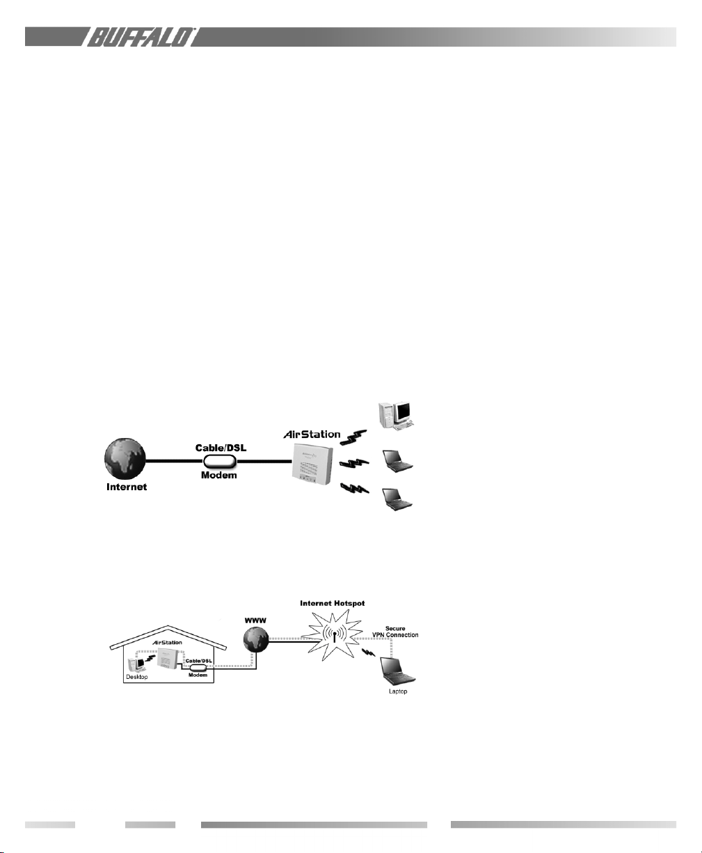
Figure 1.3
SOHO/SMB
Networking
Figure 1.4
Buffalo
Anywhere
Networking
- Firewall and DMZ zone functions to
prevent unknown intruders.
- Internal Network Security, for blocking
changes to AP configuration by wireless
clients or through another AP.
• Buffalo’s 1-2-3 connection method.
• Versatile static and dynamic routing
methods between WAN and LAN based
on the updated routing table. An economical way to bridge multiple networks.
• Remote monitoring and setup of the AP.
• Optional external antennas for boosting
the range and signal quality.
• Resistance to environmental conditions.
1.3 SOHO/SMB Networking
Connect the Buffalo AirStation Versatile AP
to a CATV or DSL modem in order to:
• Share broadband access
• Share files and printers
• Bridge between multiple networks and
multiple PC platforms
• Provide easy and secure access to home or
company networks from remote locations
1.4 Buffalo Anywhere Networking
Connect securely to a private network from
hotspots through a virtual private network
(VPN). Other remote control features make
a home network system accessible from
anywhere.
Buffalo’s firewall function provides:
• Protection of personal data/files by either
eliminating the intruder on the spot or
sending intruders to a non-functional zone
• Notification of the attack
1.5 AirStation Versatile Access Point
Package
The AirStation WLMR-L11 package consists
of the following items. If any item is missing,
please contact the seller.
1. WLMR-L11G Access Point
2. AC adapter
3. Power cable
4. CAT5 straight cable
5. WLMR-L11G Manual
6. WLMR-L11G utility CD
7. Warranty and Registration card
2
Page 3
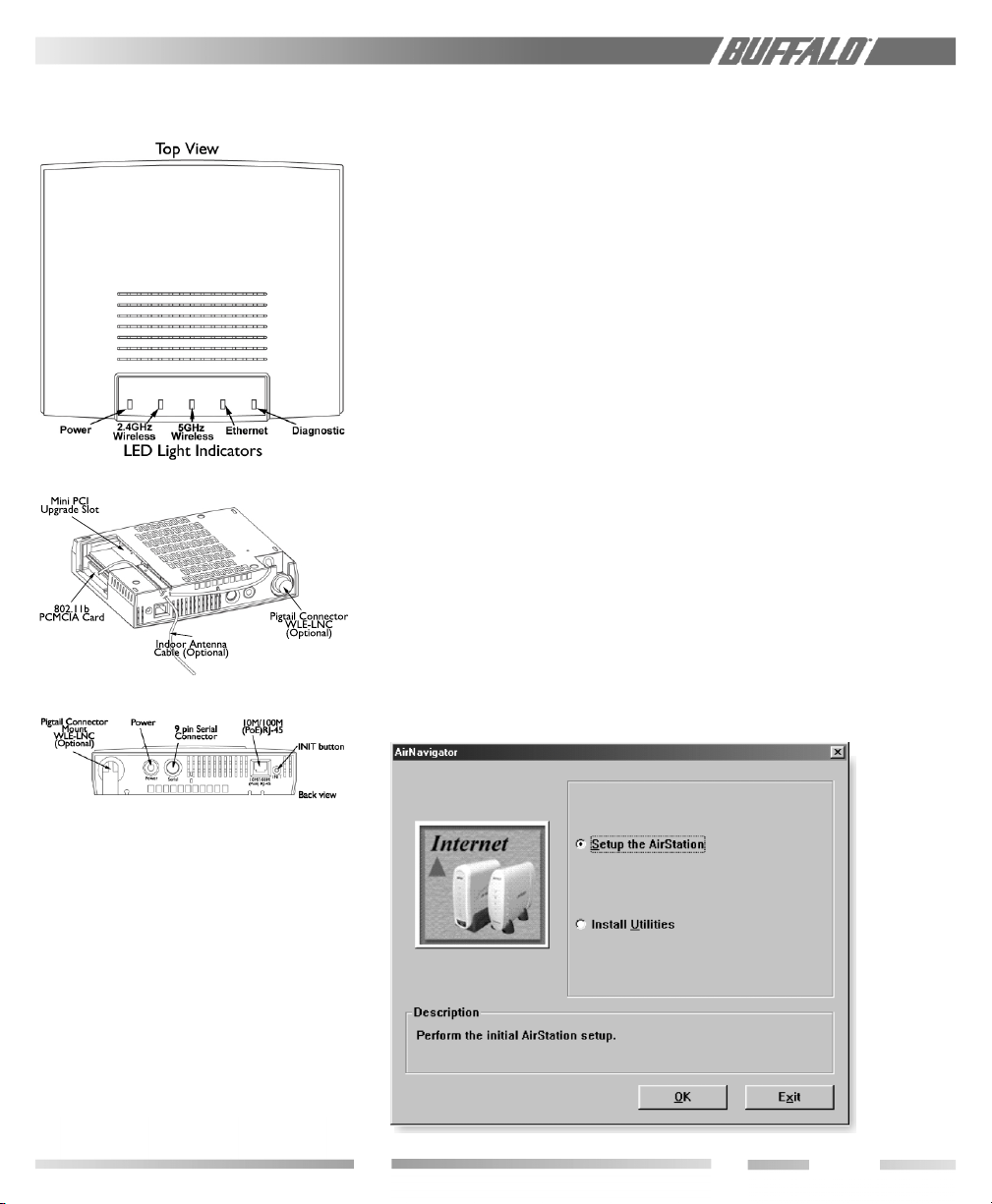
1.6 Product Views
firmware become available. Before you
proceed with the installation of this product,
please consult the AirStation website
(http://www.buffalotech.com) to
download and install the latest software for
your product.
BASIC SETUP
2.1 Using AirNavigator
For easy setup, the WLMR-L11G CD
contains a web-based utility, AirNavigator.
Use it to set up the wireless LAN environment for both AP and PC (client). The
system requires Explorer 4.0 or higher, or
Netscape Communicator 4.0 or higher.
To set up the parameters manually, refer to
chapter 3. Before installation, verify the PC is
set up for browsing the Internet.
1. Insert the CD into the CD drive. The
following screen will appear. For
AirStation setup, select “Setup the
AirStation” and click OK.
1.7 About the AirStation CD
Prior to copying or installing the software,
please read the Software License Agreement
“license.txt”, located in the root folder of the
CD. By installing, copying or using the
AirStation software, you are consenting to the
terms of this agreement. If you do not agree
to all of the terms of the Software License
Agreement, do not download, copy or install
the AirStation software. It is the policy of
Buffalo Technology to improve products as
new technology, components, software and
2.1.1
AirStation
Setup
3
Page 4
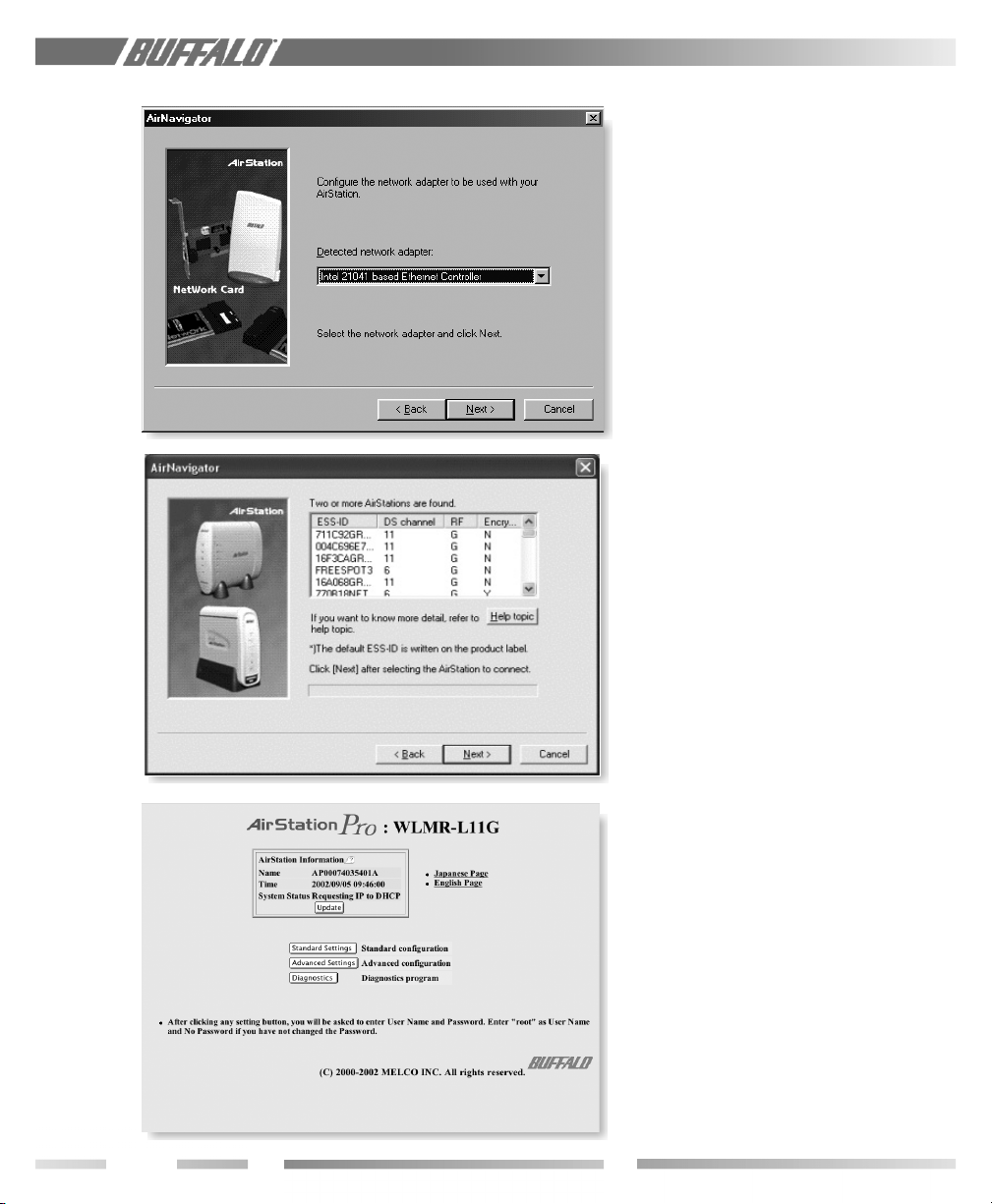
Figure 2.1.2
AirStation
Setup:
Network
Adapter
2. The Network Adapter confirmation screen
will appear. Verify the adapter shown
matches that of the PC.
Figure 2.1.3
AirStation
Setup: ESS-ID
Figure 2.1.4
AirStation
Setup:
Completion
3. Click Next until a list of access points
shows up in the ESS-ID field. Select the
one you want to communicate with and
highlight it. Click Next.
4. If the following screen is shown, connection to the access point is complete.
4
Page 5
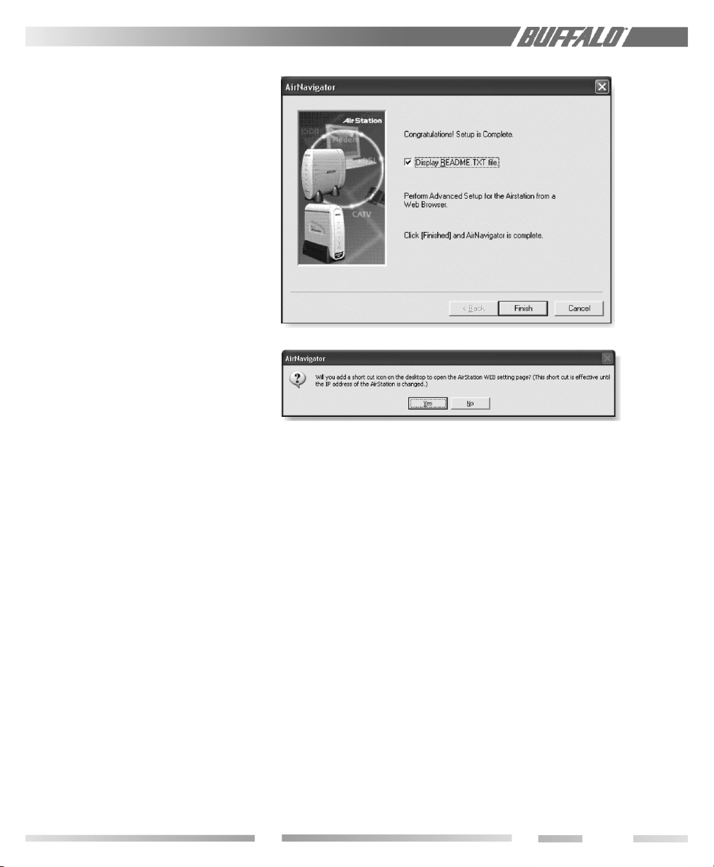
5. Click Finish.
Figure 2.1.5
AirStation
Setup:
Completion
6. To place a shortcut icon on the desktop,
click Ye s . Otherwise, click No.
STANDARD SETTINGS
3.1 Introduction
Setting up the AirStation parameters using
Buffalo’s utility tool, Client Manager, requires
basic wireless configuration knowledge.
Setup includes manual wireless configuration
and basic administrative management.
Explanation of each parameter and details of
how to use the parameter are described in
the next chapter.
3.2 Setup Preparation
Make note of the WLMR-L11G’s wired MAC
address (found on the bottom label of the
WLMR-L11G).
3.3 Setup Overview
The WLMR-L11G CD contains the Client
Manager program. The Client Manager is
used for setting up and configuring the access
point and for monitoring the wireless signal
between the AP and client.
A general setup process follows. Specialized
setups for security, filtering and other features
will be explained in later sections.
Figure 2.1.6
AirStation
Setup:
Shortcut
3.4 Open the Setup Screen
• Connect the WLMR-L11G according to the
wiring instructions.
• Install the setup utility, Client Manager, from
the CD.
• The WLMR-L11G has a default LAN IP
address of 192.168.0.1 and Subnet Mask of
255.255.255.0.
Ex: The setting PC can use 192.168.0.2 as
an IP and 255.255.255.0 as the Subnet
Mask during setup unless a different IP
range is entered for the AirStation.
1. Click Start and select Programs ➔
AirStation Utility ➔ Client Manager
2. Select Edit ➔ Search AirStation to find the
nearest AirStation.
3. Highlight the WLMR-L11G, click the
Admin menu button, then the Configure
AirStation tab to open the setup screen.
4. Select the language. English and Japanese
are available.
5
Page 6
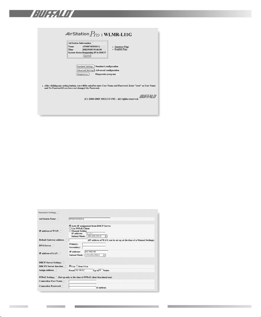
Figure 3.4.4
AirStation
Setup:
Language
Selection
Figure 3.5.10
AirStation
Setup:
Standard
Settings
3.5 Input Parameters Through the
Client Manager
1. Click the Standard Settings button to
open the next page.
2. In the password page, enter the following
information:
User Name: root
Password: [leave blank]
Click OK.
3. AirStation Name: Allows the administrator to
choose a unique AirStation name to
distinguish between multiple AirStations on
the same network.
4. Default Gateway address: If ISP supplies a
Gateway IP, enter it here. Otherwise, leave
blank.
5. DNS Server: If ISP supplies DNS addresses,
enter them here. Otherwise, leave blank.
6. IP address of LAN: Allows the administrator
to specify an IP address and Subnet Mask.
7. DHCP Server function: Allows the
administrator to set up the AirStation’s
DHCP server functions for the wireless
LAN. Select Use to enable the DHCP
server. Select Don’t Use to disable the
DHCP server.
8. Assign address: Allows administrator to set
the range of IP addresses given by the
DHCP server. Enter the first address, then
specify the number of addresses to follow.
Allows up to 253 consecutive addresses
(nodes).
9. PPPoE Settings: Allows administrator to
configure the PPPoE client function. Specify
up to 64 characters for User Name. The ISP
supplies password. Password must be
reentered for confirmation of password.If
the service name or other parameters are
required for the PPPoE connection, enter
them in the Advanced Settings/PPPoE screen.
10. Click Set. If new addresses were entered,
the setting PC will require addresses in the
same range as the AirStation. Enter the new
address scheme in the setting PC and use
Client Manager to reconnect to the
AirStation.
6
Page 7
USING AIRSTATION FOR
ADVANCED
CONFIGURATIONS
4.1 Introduction
Although your AirStation will function fine
using only the settings from Section 3, you
may wish to explore more advanced options.
This chapter explains each parameter in the
“Advanced Settings” screens. Open the initial
Setup screen and select Advanced
Settings.
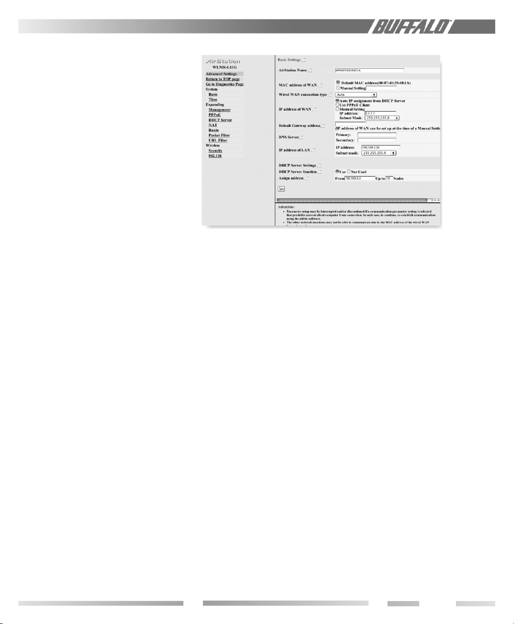
4.1.1 AirStation Name
A unique name can be set for your
AirStation in order for clients to recognize it.
It differentiates each access point when
multiple access points are present. Once it is
set, the name will be shown in the top of the
initial setup page.
4.1.2 MAC Address of WAN
The AirStation MAC address to be used for
WAN communication is set either automatically or manually.
4.1.3 Wired WAN connection type
The following options are possible for the
wired LAN port setting:
10 Mbps Half Duplex
10 Mbps Full Duplex
100 Mbps Half Duplex
100 Mbps Full Duplex
Auto Selection
The WLMR-L11G’s communication method
should be set to Full Duplex if the port
selection at the LAN hub is set to Full
Duplex. Otherwise you can select Auto or
Half Duplex on the WLMR-L11G side.
4.1.4 IP Address of WAN
Allows administrator to select DHCP server,
PPPoE, or manual setting for the WAN port
of the AirStation.
Figure 4.1
Advanced
Configuration
Screen
4.1.4.1 Auto IP assignment from DHCP
Server
DHCP may be used by selecting Auto IP
assignment from DHCP Server. The
DHCP client function of the AirStation will
pick up the address parameters supplied by a
DHCP server.
4.1.4.2 Use PPPoE Client
PPPoE may be used by selecting Use PPPoE
Client. Further parameters may be entered
on the Advanced Settings/PPPoE screen.
4.1.4.3 Manual Setting
If a DHCP server is not available for the
WAN port, static addresses must be entered.
Select Manual Setting and enter the
appropriate addresses for the network.
4.1.5 Default Gateway address
A default gateway IP should be assigned to the
AirStation. If unknown, leave the box blank. If
Auto IP assignment from DHCP Server
is selected in section 4.1.4.1, a gateway IP will
be assigned automatically, provided the DHCP
server is set to provide one.
7
Page 8
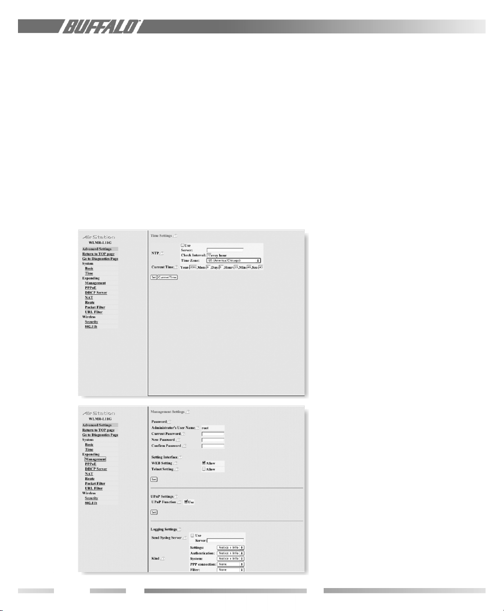
Figure 4.2
Time Setup
4.1.6 DNS Server
Input the DNS address(es) of the server to
be used by the WLMR-L11G for DNS
resolution. If DNS is not used, leave blank. If
“Auto IP assignment from DHCP Server” is
selected in section 4.1.4.1, DNS addresses will
be assigned automatically, provided the DHCP
server is set to provide them.
4.1.7 IP address of LAN
Allows administrator to specify a static IP and
Subnet Mask for the LAN side of the
AirStation.
4.1.8 DHCP Server function
Allows administrator to enable/disable the
DHCP server function for the AirStation LAN
side. Select Use to enable and Not Used
to disable the function.
4.1.9 Assign address
Sets the beginning address and range of
addresses to be assigned by the AirStation’s
DHCP server function. Select up to 253
consecutive addresses (nodes).
4.1.10 Click Set
Click Set to save the settings to the
AirStation.
4.2 Time
Set the time to synchronize the log outputs
to the correct time.
4.2.1 NTP
Check the NTP (Network Time Protocol) box to use an external time source. If
checked, specify the address of the time
server, update interval, and time zone of
AirStation. If NTP is used, manual set up of
time is disabled. Click Set.
Figure 4.3
Management
Settings
4.2.2 Current Time
Leave the NTP box unchecked. Enter the
current time. Click Set.
4.3 Management (Management
Settings)
4.3.1 Password
Allows the administrator to enter an
administrator password to restrict access to
the setting screens.
• Current Password-Enter current password
when changing the password. If setting a
password for the first time, leave blank.
• New Password-Enter new password. Use
up to eight alphanumeric characters and
the underscore (_) symbol for the
password.
8
Page 9

• Confirm Password-Reenter the new
password for confirmation.
Click Set.
4.3.2 Setting Interface
Limits the interfaces allowed for AirStation
setup. Web (browser) and Telnet settings are
options.
4.3.3 UPnP Settings
Select Use to enable UPnP (Universal Plug
and Play) support. When a computer with
UPnP support connects to the AirStation, the
computer obtains configuration information
from the AirStation. Click Set.
4.3.4 Logging Settings
• Send Syslog Server-Select Use and enter
the address of the Syslog server. Syslog
reports will be sent to this server. Refer to
the Syslog server’s documentation for
exact settings.
• Kind-Select the types of reports to be sent
to the Syslog server.
Click Set.
4.4 PPPoE
4.4.1 Connection User Name
Enter user name (up to 64 alphanumeric
characters) for PPPoE authorization.
4.4.2 Connection Password
Enter ISP provided password (up to 64
alphanumeric characters). Reenter password
in Confirm box.
4.4.4 Connection Type
Select from:
• Continuous Connection-Connects
immediately after setting and never
disconnects.
• Connect on Demand-Reconnects when
the Disconnect time elapses.
• Manual-Disables Automatic Connection.
Connect to Internet using Connect
button on initial settings page. Connect
button will not appear until PPPoE is set.
4.4.5 Disconnect Time
Specify number of minutes (0-1440) before
automatic disconnect is performed. If zero is
entered, disconnect function is disabled. If
Continuous Connection is selected, timer is
disabled.
4.4.6 No Key
Authorization Method for accessing the ISP
PPPoE server. If unknown, select Auto
authorization.
4.4.7 MRU (Maximum Receive Unit)
Maximum Receive Unit (578-1492) when
using PPPoE.
Figure 4.4
PPPoE
Configuration
4.4.3 Service Name
Enter PPPoE service name (up to 64
alphanumeric characters). If ISP doesn’t
require service name, leave blank.
9
Page 10
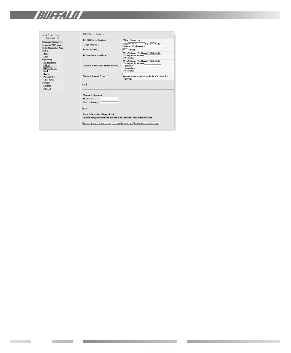
Figure 4.5
DHCP Server
Settings
4.4.8 Keep Alive
Enables the PPPoE client to send a Link
Control Protocol (LCP) echo request to the
PPPoE server once per minute. If there is no
reply within six minutes, the client disconnects. Set to Disable if frequent disconnection occurs.
4.4.9 Set
Click Set.
4.5 DHCP Server (Settings)
4.5.1 DHCP Server function
Select Use to enable or Don’t Use to
disable the LAN DHCP Server function in the
AirStation.
4.5.2 Assign Address
Allows administrator to specify the starting IP
address and range of addresses (nodes) for
DHCP Server function. Allows selected
addresses to be excluded.
4.5.3 Lease Duration
Specifies the number of hours (1-999) an
assigned IP address is valid. The client PC will
request a renewal of IP address at the end of
the valid time period.
4.5.4 Default Gateway address
Allows administrator to use the Default
Gateway address (the AirStation’s IP address),
assign a specific Gateway address, or block
clients from notice of a Gateway.
4.5.5 Notice of DNS (Name) Server Address
Allows administrator to use the default DNS
address (the AirStation’s IP address), assign a
specific DNS address, or block clients from
notice of a DNS address.
4.5.6 Notice of Domain Name
Domain name will be sent to LAN PCs when
an IP address is assigned. Enter a maximum of
64 alphanumerical characters. Click Set.
4.5.7 Manual Assignment
Allows a PC to receive a specific IP address
when a specific MAC address is detected.
• Enter the IP address to be assigned to a
specific MAC address.
• Enter the matching MAC address for the IP
address. Click Add.
4.6 NAT (Network Address Translation
Settings)
4.6.1 Address Translation
Select Use or Don’t Use. Address Transla-
tion must be enabled for client PCs to connect
to the Internet. Selecting Use enables the
following functions:
• IP Masquerade-When the LAN PC
connects to the WAN side, the IP address of
LAN PC is dynamically translated to
become the WAN IP address of the
AirStation. Multiple LAN PCs can share one
WAN IP address to access the Internet.
• Static IP address translation-When the
WAN requests connection to the LAN, the
WAN IP address of the AirStation is
translated into the IP address of the LAN
PC.
Click Set.
10
Page 11

4.6.2 DMZ Address/Log Output
• DMZ-Enter DMZ’s IP address. Incoming
packets containing no recognizable
destination port information will be
redirected to the DMZ’s IP address.
• Select Log Output of the canceled
packet information to record a Log
Output for discarded packets.
Select Set.
4.6.3 IP address of WAN
Select AirStation’s IP address of WAN
or Manual setting. For Manual setting,
enter the IP address used by the WAN PC to
connect to the local PC. Some network
applications (online games or streaming
software) require adding Address Translation
tables.
4.6.4 Protocol
• Select FTP or HTTP. Configures
necessary protocol to translate.
• All-Selects all IP protocols.
• Manual-Specify the protocol by protocol
number (0-255).
• ICMP-Network Diagnostic Protocol (1).
• Optional-Select Protocol number
• TCP/UDP Optional Port-Select TCP
or UDP, then enter port number.
Figure 4.6
NAT Settings
Figure 4.7
Route
Settings
4.6.5 IP address of LAN
Select Manual and enter the destination IP
address of the LAN PC; or select
AirStation’s IP address of LAN.
• Select Add to NAT table.
4.6.6 NAT Table (Display/Delete)
• Allows administrator to delete NAT tables.
4.7 Route
Set communication routing between the
WLMR-L11G and other network devices in
the same network.
4.7.1 Route Settings
Set RIP information received by WLMR-L11G
for each parameter. Select Both RIP1 and
RIP2, RIP1, RIP2 or None (no RIP).
• Click Set.
4.7.2 Add Routing Table Entry
Set routing information.
Destination address=Network IP address
and the subnet mask for the destination.
11
Page 12
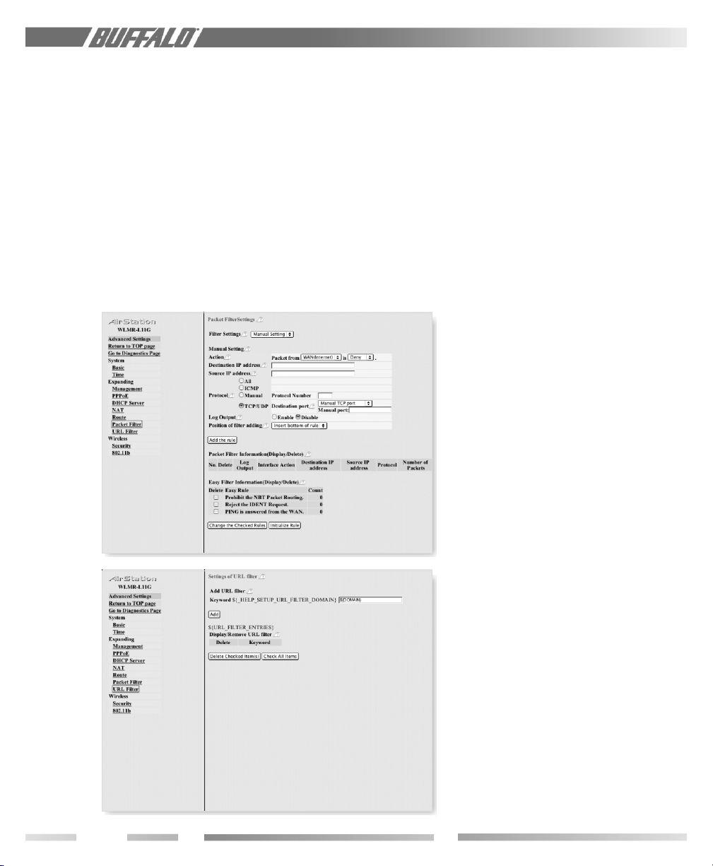
Figure 4.8
Packet
Filtering
Gateway=Address through which the
packet passes before it reaches the
destination address.
Metric=Number of routers (1-15) to be
passed before the packet reaches its
destination.
• Click Add.
4.7.3 Routing Table Entries (Display/Delete)
Allows administrator to delete Routing tables.
4.8 Packet Filter (Packet Filter
Settings)
Configures packet restrictions.
4.8.1 Setup for filtering
• Action-If administrator selects Packet
from LAN is Deny or Reject, the
administrator will no longer have access to
the AirStation configuration screens.
This function prohibits setup from a wireless
PC. The WLMR-L11G can be returned to the
factory default settings (ALL of them!) by
holding down the INIT button on the back of
the unit for three seconds.
Filtering is controlled by the following
parameters:
- Destination IP Address
- Source IP Address
- Protocol (all protocols, ICMP, arbitrary
protocol number, TCP/UDP protocol
number)
- Destination port number
- Log of filtering Click Add the rule.
4.9 URL Filter
Allows administrator to configure URL filter
settings. Enter key words for the AirStation to
block from Internet access.
Figure 4.9
URL Filtering
4.10 Security/MAC Restrict
Select “Security”, then “MAC Restrict” from
the menu on the left.
■ Note: If configuring from a wireless PC,
add your MAC address to the list of authorized wireless LAN PCs.
4.10.1 MAC Restrict Settings
Add MAC addresses to the authorized list
manually. If RADIUS is enabled, the client
must first be authenticated. Enter the MAC
address in the “MAC address of wireless LAN
PC” field and click Add. The MAC address
must be in two-digit groups separated by
colons.
Example: 00:40:26:00:11:22
12
Page 13

4.10.2 List of the Wireless PC(s)
Click Look for Wireless LAN PC(s) to
display the current list of wireless PCs
communicating with the WLMR-L11G.
Check the Registration box and click the
Change button to add a MAC address to
the list of Authorized wireless LAN PCs.
4.10.3 Authorized Wireless LAN PCs
Displays all MAC addresses that are allowed
to communicate with the WLMR-L11G. The
status shows the current active MAC
addresses on the network (0=currently
connected). To eliminate a specific MAC
address from the network, check the Delete
box and click the Change button.
■ Note: MAC Address Restriction must be
enabled in the next section for MAC
Restriction to be active.
4.11 Security/802.11b
Select “Security”, then “802.11b” from the
menu on the left. Restrict access from
wireless LAN PCs by MAC address restriction and EAP authentication.
Figure 4.10
Security/MAC
Restrict
Figure 4.11
Security/
802.11b
4.11.1 MAC Access Restriction
Click Enable to activate MAC access
restriction set up in the previous section.
4.11.2 EAP Authentication
Enable and configure EAP protocol authorization. The WLMR-L11G supports EAP-MD5,
EAP-TLS and chooses either method
automatically. If Enable is selected, the
following configuration is required:
• Configure 802.1x or EAP settings of the
wireless LAN PC.
• Register user account and set EAP to the
RADIUS server. If WEP Dynamic
Change is selected, automatic generation,
automatic delivery, and continuous renewal
of the WEP key is performed.
4.11.3 Encryption Code (WEP)
Set the encryption code used in wireless
communications. The WEP key must match
between two parties for secure communications. If multiple keys are used, the order
must match. For a 40bit WEP wireless card to
communicate, all WEP must be limited to
40bit (104/128bit WEP may not be used).
Examples of WEP key:
40bit ASCII: 5 digits of alphanumeric
characters, “ab34Y”
104bit ASCII: 13 digits of alphanumeric
characters, “123456abcdef7”
13
Page 14
■ Note: ASCII WEP is case sensitive.
40bit HEX: 10 digits, using characters 0-9
and a-f, “00234ABCDE”
104bit HEX: 26 digits, using characters 0-9
and a-f, “20123456789abcdeabcdewxyzh”
Click Set.
and asks for communication approval to the
client. Once the RADIUS recognizes the
client, the RADIUS issues a key to the
AirStation and the client for initiation of
communication. Clients must register with a
RADIUS server on a network, before wireless
authentication is possible.
Figure 4.12
RADIUS
Settings
Figure 4.13
802.11b
Settings
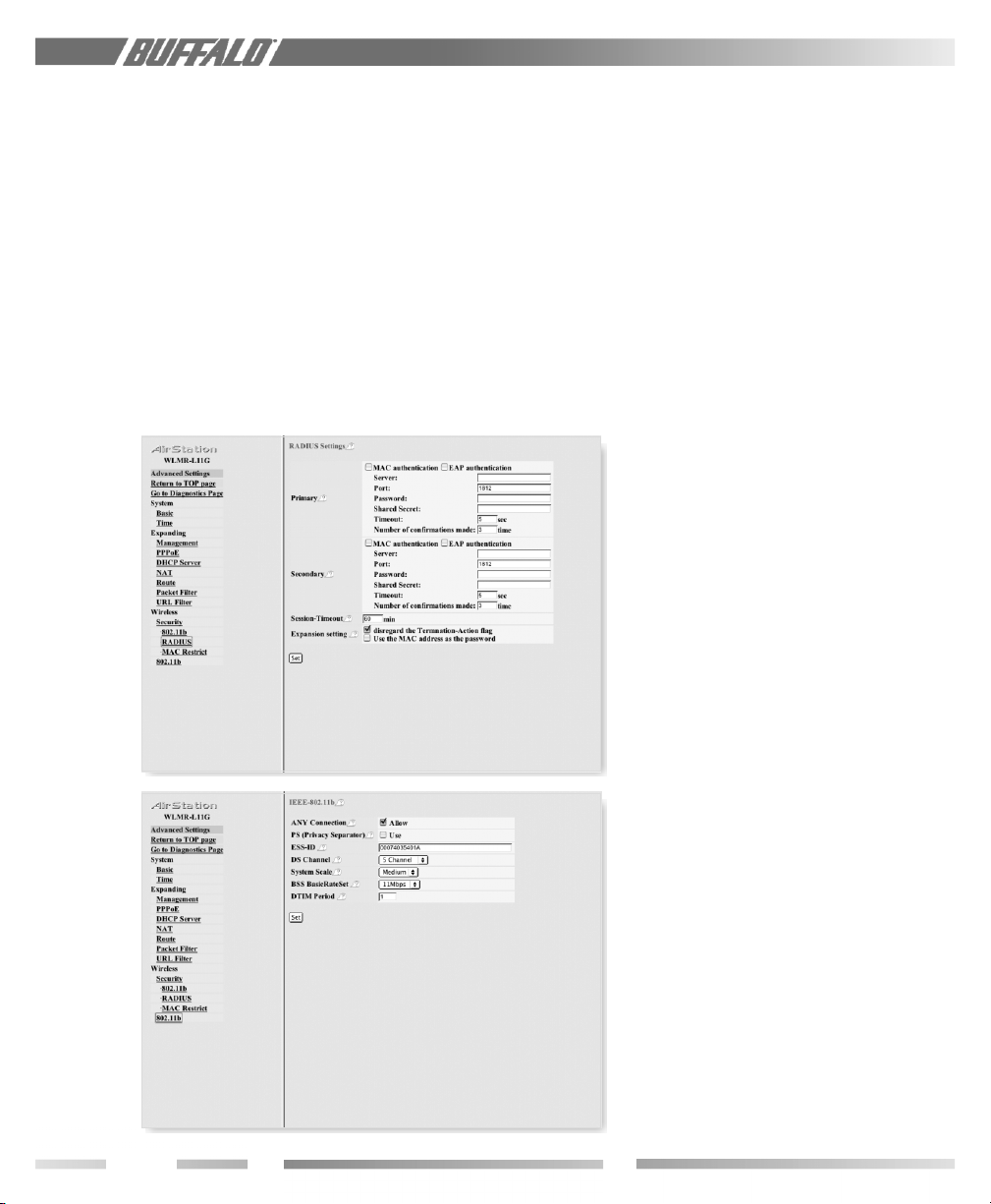
4.12 Security/RADIUS
Select “Security”, then “RADIUS” from the
menu on the left. Set up RADIUS parameters.
When a client requests communication with
the WLMR-L11G, the WLMR-L11G reports
its own MAC address to the RADIUS server
4.12.1 RADIUS with MAC/EAP
Authentication
Set up the authentication by MAC address or
EAP. If EAP authentication is selected, set
the following parameters:
- Server = Name of the RADIUS server
or IP address.
- Port = Number to be used by the
RADIUS upon authentication. AirStation
default is port 1812. Some RADIUS
servers use port 1645.
- Password = Password for RADIUS
server.
- Shared Secret=Use lower case alphanumeric characters between 1-255.
- Timeout = Number of seconds for
connecting to a RADIUS server before
the AirStation will time out.
- Number of confirmations made =
Number of times the AirStation will try
to connect to a RADIUS server. If a
Secondary RADIUS ser ver is set up, the
AirStation will attempt authentication
with the Secondary.
4.13 802.11b
4.13.1 ANY Connection
Enables a client PC to connect to the nearest
WLMR-L11G by entering the word “any” for
the ESS-ID. If the “ANY Connection” is
deselected, the WLMR-L11G will not be
found using the ESS-ID of “any” in the client
PC.
14
4.13.2 PS (Privacy Separator)
Enables a client PC to connect to the nearest
WLMR-L11G, blocking communications to
and from other clients.
Page 15

4.13.3 ESS-ID (Auto or Manual Set) and
Roaming
Allows administrator to alter the ESS-ID of
the AirStation. To communicate with a
specific AP only, the AP’s ESS-ID must be
entered in the client PC. The client PC looks
for the specific AP (or ESS-ID) for wireless
communication. Use up to 32 alphanumeric
characters for the ESS-ID (case sensitive).
When AirStations have an identical ESS-ID,
WEP, and DS channel, client PCs may Roam
between the AirStations.
4.13.4 DS Channel
Channel used for wireless communication.
There are 11 channels.
■ Note: This is automatically set in the client
computer.
4.13.5 System Scale (Roaming Area Range)
Mini = 10 to 20 meters.
Small = 20 to 40 meters
Medium = 40 to 60 meters
Large = Above 60 meters
Roaming distance varies with the wireless
environment.
Allows configuration of the Roaming area
around the WLMR-L11G. For difficulty in
Roaming, change to a Small or Mini setting,
which will switch the client PC to another
access point more quickly.
■ Note: The client card must support this
feature.
interval time (1-255 sec.). Selection of a larger
number may save energy consumption for the
client PC (when client power management is
enabled), but may delay wireless communication. The default value of 1 is recommended.
NETWORK DIAGNOSIS
USING THE AIRSTATION
5.1 Unit Information
Model Name = AirStation model name
and firmware version number
AirStation Name = Alias for the AirStation
Wireless module firmware = Wireless LAN
card model name and firmware version
number
(Wired) MAC address = WLMR-L11G’s
wired side MAC address
(Wireless) MAC address = WLMR-L11G’s
wireless side MAC address
IEEE-802.11b = Indicates wireless communications setting such as ANY connection,
ESS-ID connection, WEP, Channel
IP address = Selection for setting the IP
address. If auto IP address acquisition from
the DHCP server is selected, the acquisition success or failed parameter will be
shown.
Figure 5.1
Unit
Information
4.13.6 BSS (Basic Service Set) Basic Rate
The transmission data rate between devices.
If one device supports 2Mbps only, the data
rate for the entire network should be limited
to 2Mbps. Otherwise, use 11Mbps max.
4.13.7 DTIM Period
An access point transmits beacon signals to
nearby clients at a preset interval. This
parameter sets the beacon transmission
15
Page 16

Figure 5.2
Transfer
Packet
Information
Auto IP address acquisition = Acquisition
of the IP address from the DHCP or
update is performed. Once the IP address
is released to the DHCP, the WLMR-L11G
must be restarted or renewed using the
button marked RENEW to get the new
IP address in order to re-connect to the
WLMR-L11G.
5.2 Transfer Packet
Displays the packet volume and errors for
transmission sending/receiving with wired
and wireless communication.
Figure 5.3
Wireless LAN
PC
Figure 5.4
Ping Test
5.3 Wireless LAN PC Information
Displays all MAC addresses of PCs communicating wirelessly with the WLMR-L11G.
5.4 Ping Test
The WLMR-L11G issues a ping test to the
target IP address in order to confirm the
communication link. Enter the target device’s
IP address and click Exec.
16
Page 17

5.5 Log Information
Includes system operation, setup history,
Login approval, and wireless communication
access approval.
Figure 5.5
Log
Information
5.5 Updating Firmware
Allows the administrator to update firmware
from a specified Web server using the HTTP
protocol. Specify the URL containing new
firmware. When using a proxy server, select
Use, and enter the IP address and port
number of the Proxy server. Click Exec.
5.6 Set to Default
Sets all parameters back to factory defaults.
After the reinitialization, the AirStation must
be restarted. Selecting Restart the
AirStation restarts the WLMR-L11G
without initialized values.
Figure 5.6
Updating
Firmware
Figure 5.7
Set to Default
17
Page 18

ADDITIONAL
INFORMATION
For more information, please consult one of
the following:
• The on-line help system of your
AirStation wireless system - for information about software and driver functionality.
• The AirStation website at: http://
www.buffalotech.com – for frequently
asked questions (FAQ’s) and Software
Updates.
18
Page 19

APPENDIX A
WLMR-L11G ACCESS POINT SPECIFICATIONS
Physical Specifications
Dimensions (LxWxH) 195 x 169 x 46 mm
Weight 620 grams
Temperature & Humidity
Operation 0° to 60° C
Maximum humidity 90%
Transit/Storage -20° to 75° C maximum humidity 95% (no condensation)
Power Characteristics
Transmit Mode 1.2A (Nominal), (0.16 A with PoE)
Power Supply 5 V (48V with PoE)
Regulatory Information
Wireless communication is often subject to local radio regulations. Although AirStation wireless
networking products have been designed for operation in the license-free 2.4 GHz band, local
radio regulations may impose limitations on the use of wireless communication equipment.
Networking Characteristics
Compatibility
• IEEE 802.11 Standard for Wireless LANs (DSSS)
• Wi-Fi (Wireless Fidelity) certified by the Wireless Ethernet Compatibility Alliance (WECA).
Host Operating System
• Microsoft Windows(r) ME/98/NT4.0/2000/XP, Unix/Linux/MacOS
• NDIS5 Miniport Driver Media Access Protocol CSMA/CA (Collision Avoidance) with
Acknowledgment (ACK)
Radio Characteristics
R-F Frequency Band 2.4 GHz (2400-2500 MHz)
11 selectable sub-channels
Modulation Technique Direct Sequence Spread Spectrum
• CCK for High & Medium Transmit Rate
• DQPSK for Standard Transmit Rate
• DBPSK for Low Transmit Rate
Spreading 11-chip Barker Sequence
Bit Error Rate (BER) Better than 10 -5
Nominal Output Power 15 dBm
19
Page 20

Transmit Rate / Range
High Speed 11 Mbps
Medium Speed 5.5 Mbps
Standard Speed 2 Mbps
Low Speed 1 Mbps
Open Office Environment
160 m (525 ft.)
270 m (885 ft.)
400 m (1300 ft.)
550 m (1750 ft.)
Semi-Open Office Environment
50 m (165 ft.)
70 m (230 ft.)
90 m (300 ft.)
115 m (375 ft.)
Closed Office
25 m (80 ft.)
35 m (115 ft.)
40 m (130 ft.)
50 m (165 ft.)
Receiver Sensitivity -83 dBm -87 dBm -91 dBm -94 dBm (depends on data rate)
Delay Spread (at FER of <1%) 65 ns 225 ns 400 ns 500 ns (depends on data rate)
• The range of wireless devices can be affected by metal surfaces, solid high-density materials
and obstacles in the signal path.
Table “Radio Characteristics” lists the typical ranges when used indoors:
• In Open Office environments, clients can “see” each other, i.e. there are no physical obstructions between them.
• In Semi-open Office environments, work space is separated by room dividers; client cards are
at desktop level.
• In Closed Office environments, workspace is separated by floor-to-ceiling brick walls.
■ NOTE: The range values listed in Table “Radio Characteristics” are typical distances as
measured at Buffalo Technology AirStation laboratories. These values are provided for your
guidance but may vary according to the actual radio conditions at the location where the
AirStation product is installed.
20
AirStation IEEE 802.11 Channel Sets
The range of the wireless signal is related to the Transmit Rate of the wireless communication.
Communications at a lower Transmit range may travel longer distances.
Channel ID FCC
1 2412 4 2427 7 2442 10 2457
2 2417 5 2432 8 2447 11 2462
†
3 2422 6 2437 9 2452
†
Default Channel
Page 21

TROUBLESHOOTING
B.1 Common Troubleshooting Tips
Common Problems
• Out of range, client cannot connect to the AirStation.
• Configuration mismatch, client cannot connect to the AirStation.
• Absence or conflict with the Client Driver.
• Conflict of another device with the AirStation hardware.
B.1.1 LED Activity B
Monitoring LED activity helps identify problems.
- Power LED should be GREEN,
- Wireless LED should be GREEN if the line is active. If is it blinking GREEN, wireless
communication is active.
- Ethernet LED should be GREEN (100Mbps) or AMBER (10Mbps) while the communication
is active.
DIAG LED Activity
Unplug the power for three seconds. Plug the power back in to monitor the DIAG LEDs during
start-up. If the symptom matches Table B.1.1, email techsupport@buffalotech.com or call
800-688-7466 between the hours of 8:30 am and 7:30pm, CST.
Table B.1.1 DIAG LED Activity Table
DIAG LED Display Time Description/Action
Continuous Red Starting RAM Error Red flash, 2 times Starting Flash ROM Error
Red flash, 3 times Starting A problem in the wired LAN side
Red flash, 4 times Starting A problem in the wireless LAN side
Red flash, 2 times After setup is complete Flash ROM Error
Red flash, 2 times During the firmware update Flash ROM Error
B. 1.2 LEDs Work But Client PC Cannot Connect to Network
If the LEDs indicate that the network is working properly (Power LED is on, Transmit/Receive
LED blinks), check the TCP/IP settings of the network.
Changing Client TCP/IP Settings in Windows
Consult the LAN Administrator for TCP/IP settings.
To add or change the TCP/IP Settings:
1. On the Windows task bar click Start.
2. Select Settings, then Control Panel.
3. Double-click on the Network icon to view the Network Properties.
4. From the list of installed components, verify the TCP/IP -> Buffalo WLI-USB-L11G wireless
LAN adapter protocol (or appropriate wireless LAN adapter) is installed.
• If this protocol is not yet installed, click the Add button and select the TCP/IP protocol
from the list. Refer to Windows Help for more information.
21
Page 22

• If this protocol is installed, select this protocol and click the Properties button. Verify the
parameters match the settings provided by your LAN Administrator. Make changes if
necessary, and click OK.
5. When prompted, restart your computer.
B. 1.3 Other Problems
Please refer to www.buffalotech.com and www.airstation.com for further reference
materials.
22
Page 23

Glossary
10BaseT or 100BaseTx: 802.3 based
Ethernet network that uses UTP (Unshielded
twisted pair) cable and a star topology. 10 is
10 Mbps and 100 is 100 Mbps.
802.1x: The standard for wireless LAN
authentication used between an AP and a
client. 802.1x with EAP will initiate key
handling.
Ad-Hoc Network: The wireless network
based on a peer-to-peer communications
session. Also referred to as AdHoc.
Bandwidth: The transmission capacity of a
computer or a communication channel,
stated in Megabits per second (Mbps).
BSS (Basic Service Set): An 802.11
networking framework that includes an
Access Point.
Bus Mastering: A system in which the
specified Input/Output device (e.g. NIC Card)
can perform tasks without the intervention of
the CPU.
Client: A PC or workstation on a network.
Cross-Over Wiring: A UTP cable that has
its transmit and receive pair crossed to allow
communications between two devices.
DCE (Data Communications Equipment): Hardware used for communication
with a Data Terminal Equipment (DTE)
device.
Default Gateway: The IP Address of either
the nearest router or server for the LAN.
Default Parameter: Parameter set by the
manufacturer.
Destination Address: The address por tion
of a packet that identifies the intended
recipient station.
DHCP (Dynamic Host Configuration
Protocol): Based on BOOTP, it uses a pool
of IP addresses, which it assigns to each
device connected to it, and retrieves the
address when the device becomes dormant
for a period of time.
DNS (Domain Name System): System
used to map readable machine names into IP
addresses
Driver: Software that interfaces a computer
with a specific hardware device.
DSSS (Direct Sequence Spread
Spectrum): Method of spreading a wireless
signal into wide frequency bandwidth.
DTE (Data Terminal Equipment):
Device that controls data flowing to and from
a computer.
Dynamic IP Address: An IP address that is
automatically assigned to a client station in a
TCP/IP network, typically by a DHCP server.
ESS (Extended Service Set): A set of
two or more BSSs that form a single subnetwork. ESS-ID is user identification used in
the ESS LAN configuration.
Ethernet: The most widely used architecture
for Local Area Networks (LANs). It is a
shared-media network architecture. The IEEE
802.3 standard details its functionality.
Ethernet cable: A wire similar to telephone
cable that carries signals between Ethernet
devices.
File and Print Sharing: A Microsoft
application that allows computers on a
network to share files and printers.
Firmware: Programming inserted into
programmable read-only memory, thus
becoming a permanent part of a computing
device.
Frame: A fixed block of data, transmitted as a
single entity. Also referred to as packet.
Full-Duplex: To transmit on the same
channel in both directions simultaneously.
Gbps (Giga Bits per second): One billion
bits per second.
Half-duplex: To transmit on the same
channel in both directions, one direction at a
time.
Hub: A device which allows connection of
computers and other devices to form a LAN.
23
Page 24

IEEE (Institute of Electrical and
Electronics Engineers): The professional
organization which promotes development
of electronics technology.
IP (Internet Protocol) Address: A
unique 32-binary-digit number that identifies
each sender or receiver of information sent
in packets.
Infrastructure: A wireless network or
other small network in which the wireless
network devices are made a part of the
network through the Access Point.
ISP (Internet Service Provider): A
company that provides access to the Internet
and other related services.
IV (Initialization Vector): The header
section of a message packet.
LAN (Local Area Network): A group of
computers and peripheral devices connected
to share resources.
LED (Light Emitting Diode): The lights
on a hardware device representing the activity
through the ports.
MAC (Medium Access Control)
Address: A unique number that distinguishes
network cards.
Mbps (Mega Bits Per Second): A
measurement of millions of bits per second.
MDI/X (Media Dependent Interface/
Cross-over): Port on a network hub or
switch that crosses the incoming transmit lines
with the outgoing receive lines.
MHz (MegaHertz): One million cycles per
second.
MIB II: A database containing performance
information and statistics on each device in a
network.
MIPS (Million Instructions Per Second):
A measurement of processing speed.
NAT (Network Address Translation):
An internet standard that enables a LAN to
use one set of IP addresses for internal traffic
and a second set for external traffic.
NIC (Network Interface Card): A n
expansion card connected to a computer so
the computer can be connected to a
network.
Packet: A block of data that is transferred as
a single unit, also called a frame or a block.
Packet Filtering: Discarding unwanted
network traffic based on its originating
address or its type.
PCI (Peripheral Component Interconnect): A bus that is connected directly to the
CPU.
PCMCIA (Personal Computer
Memory Card International Association) Card: Removable module that adds
features to a portable computer.
Ping (Packet Internet Groper): An
Internet utility used to determine whether a
particular IP address is online.
Plug and Play: Hardware that, once
installed (“plugged in”), can immediately be
used (“played”), as opposed to hardware that
requires manual configuration.
PoE (Power over Ethernet): A mechanism to send DC power to a device using a
CAT5 Ethernet cable.
PPPoE (Point-to-Point Protocol over
Ethernet): A specification for connecting
users on an Ethernet line to the Internet
through a common broadband medium.
Protocol: A standard way of exchanging
information between computers.
RADIUS (Remote Authentication Dial
In User Service): A server that issues
authentication key to clients.
RAM (Random Access Memory): Non-
permanent memory.
Repeater Hub: A device that collects,
strengthens and transmits information to all
connected devices, allowing the network to
be extended to accommodate additional
workstations.
24
Page 25

RC4: The encryption algorithm that is used
in WEP.
RJ-45 connector: An 8-pin connector used
between a twisted pair cable and a data
transmission device.
ROM (Read Only Memory): Permanent
memory.
Router: Device that can connect individual
LANs and remote sites to a server.
Roaming: The ability to use a wireless
device while moving from one access point
to another without losing the connection.
Script: A macro or batch file containing
instructions and used by a computer to
perform a task.
Server: Any computer that makes files or
peripheral devices available to users of the
network and has a resident Network OS.
SMTP (Simple Mail Transfer Protocol):
The protocol used to define and deliver
electronic mail (e-mail) from one location to
another.
SNMP (Simple Network Management
Protocol: An application layer protocol that
outlines the formal structure for communication among network devices.
Static IP Address: A permanent IP
address is assigned to a node in a TCP/IP
network. Also known as global IP.
STP (Shielded Twisted Pair): Twisted
Pair cable wrapped in a metal sheath to
provide extra protection from external
interfering signals.
Subnet Mask: An eight-byte address
divided into 4 parts separated by periods.
TCP/IP (Transmission Control
Protocol/Internet Protocol): Protocol
used by computers when communicating
across the Internet or Intranet.
TFTP (Trivial File Transfer Protocol):
Simple form of FTP (File Transfer Protocol),
which Uses UDP (User Datagram Protocol),
rather than TCP/IP for data transport and
provides no security features.
TKIP (Temporal Key Integrity Protocol): An encryption method replacing WEP.
TKIP uses random IV and frequent key
exchanges.
Topology: The shape of a LAN (Local Area
Network) or other communications system.
Twisted Pair: Cable that comprises 2 or
more pair of insulated wires twisted together.
UDP (User Datagram Protocol): A
communication method (protocol) that offers
a limited amount of service when messages
are exchanged between computers in a
network. UDP is used as an alternative to
TCP/IP.
Uplink: Link to the next level up in a
communication hierarchy.
UTP (Unshielded Twisted Pair) cable:
Two or more unshielded wires twisted
together to form a cable.
WAN (Wide Area Network): A
networking system covering a wide geographical area.
WEP (Wired Equivalent Privacy): A n
encryption method based on 64 or 128bit
algorithm.
Web Browser: A software program that
allows viewing of web pages.
Wi-Fi (Wireless Fidelity): An organization that tests and assures interoperability
among WLAN devices.
Wire Speed: The maximum speed at which
a given packet can be transferred using
Ethernet and Fast Ethernet standard
specifications.
WLAN (Wireless LAN): A LAN
topology using wireless devices.
VPN (Virtual Private Network): A
security method to connect remote LAN
users to a corporate LAN system.
25
 Loading...