

Page 1
User Manual - WZR-HP-G300NH
High Power
Wireless N Router & AP
www.buffalotech.com
35010849 ver.01 v1.8
Page 2

Table of Contents
Introduction . . . . . . . . . . . . . . . . . . . . . . . . . . . . . . . . . . . . . . . . . . 3
Initial Setup . . . . . . . . . . . . . . . . . . . . . . . . . . . . . . . . . . . . . . . . . . 4
Automatic Installation . . . . . . . . . . . . . . . . . . . . . . . . . . . . . . 7
Manual Installation . . . . . . . . . . . . . . . . . . . . . . . . . . . . . . 8
Connecting Wireless Clients . . . . . . . . . . . . . . . . . . . . . . . . . . 11
Web Admin Tool . . . . . . . . . . . . . . . . . . . . . . . . . . . . . . . . . . . . . . . . . . . . . 14
AOSS . . . . . . . . . . . . . . . . . . . . . . . . . . . . . . . . . . . . . . . . . . . . . . . . . . . . . . . . . . . . 17
WPS . . . . . . . . . . . . . . . . . . . . . . . . . . . . . . . . . . . . . . . . . . . . . . . . . . . . . . . . . . . . . . . . . . . 20
Movie Engine (QoS) Switch . . . . . . . . . . . . . . . . . . . . . . . . . . . . . . . . . . . . . . . . . . . . . 22
Router/Access Point Mode Switch . . . . . . . . . . . . . . . . . . . . . . . . . . . . . 23
Encryption and Security . . . . . . . . . . . . . . . . . . . . . . . . . . . . . . . . . . . . . . . . . . . . . . 24
Connecting to an Existing Network. . . . . . . . . . . . . . . . . . . . . . . . . . . . . . . 26
Connecting from Outside the Network with a VPN . . . . . . . . . . . . . . . . . . . . . . . . . . . . . . . . . . . . . . 27
Dynamic DNS . . . . . . . . . . . . . . . . . . . . . . . . . . . . . . . . . . . . . . . . . . . . . . . . . . . . . . . 33
USB Devices . . . . . . . . . . . . . . . . . . . . . . . . . . . . . . . . . . . . . . . . . . . . . . . . . . . . . . . 34
Sharing . . . . . . . . . . . . . . . . . . . . . . . . . . . . . . . . . . . . . . . . . . . . . . . . 35
Disconnecting . . . . . . . . . . . . . . . . . . . . . . . . . . . . . . . . . . . . . . . . . . . . . . 39
WebAccess . . . . . . . . . . . . . . . . . . . . . . . . . . . . . . . . . . . . . . . . . . . . . . . . 40
BitTorrent . . . . . . . . . . . . . . . . . . . . . . . . . . . . . . . . . . . . . . . . . . . . . . . . 44
Specications . . . . . . . . . . . . . . . . . . . . . . . . . . . . . . . . . . . . . . . . . . . . . . 46
Troubleshooting . . . . . . . . . . . . . . . . . . . . . . . . . . . . . . . . . . . . . . . . . . . . . . . . . 48
Glossary . . . . . . . . . . . . . . . . . . . . . . . . . . . . . . . . . . . . . . . . . . . . . . . . . . . . . . . . . . . . . 50
Warranty . . . . . . . . . . . . . . . . . . . . . . . . . . . . . . . . . . . . . . . . . . . . . . . . . . . . . . . . . 62
Contact Information . . . . . . . . . . . . . . . . . . . . . . . . . . . . . . . . . . . . . . . . . . . . . . . . . . . . . . . . . . 63
GPL Information . . . . . . . . . . . . . . . . . . . . . . . . . . . . . . . . . . . . . . . . . . . . . . . . . . . . . . . . 65
2
Page 3

Introduction
Work and play - further and faster! Your AirStation Nniti combines gigabit Ethernet
networking with extended wireless range and speed. It offers excellent compatibility with
most wireless clients, giving superb performance with Wireless-N, Wireless-G, and legacy
Wireless-B clients. For best overall performance, use with Buffalo Technology Nniti
wireless clients.
System Requirements:
• A high-speed (Broadband) Internet connection or existing local area connection.
• A computer with a network connection (wired or wireless) and a web browser such as
Firefox, Internet Explorer, Opera, or Safari.
Package Contents:
• WZR-HP-G300NH AirStation
• AC adapter
• CAT5 LAN cable
• Screws for wall mounting
• Utility CD with User Manual
• Quick Setup Guide
• Warranty Statement
3
Page 4

Initial Setup
Begin by nding a good place to set up your router/access point. Some things to
consider:
• You’ll need to be able to plug your internet connection into it, so it should go within
reach of the LAN cable from your DSL or Cable modem. You’ll also want a power outlet
nearby.
• Keep the access point as central in your work area as possible. Signal strength and
speed fall off with distance.
• Higher is often better. For instance, set it up on the top shelf of a bookcase rather than
the bottom one, if possible.
Do you need a password or other information to log in to your internet connection?
Many DSL connections require information like global IP address, subnet mask, default
gateway address, DNS server address, or PPPoE parameters in order to connect. Cable
modems usually don’t require extra information. If you have a DSL internet connection,
make sure that you have any necessary information handy before you continue. Your
Internet Service Provider can give you this information if you don’t know it.
4
Page 5
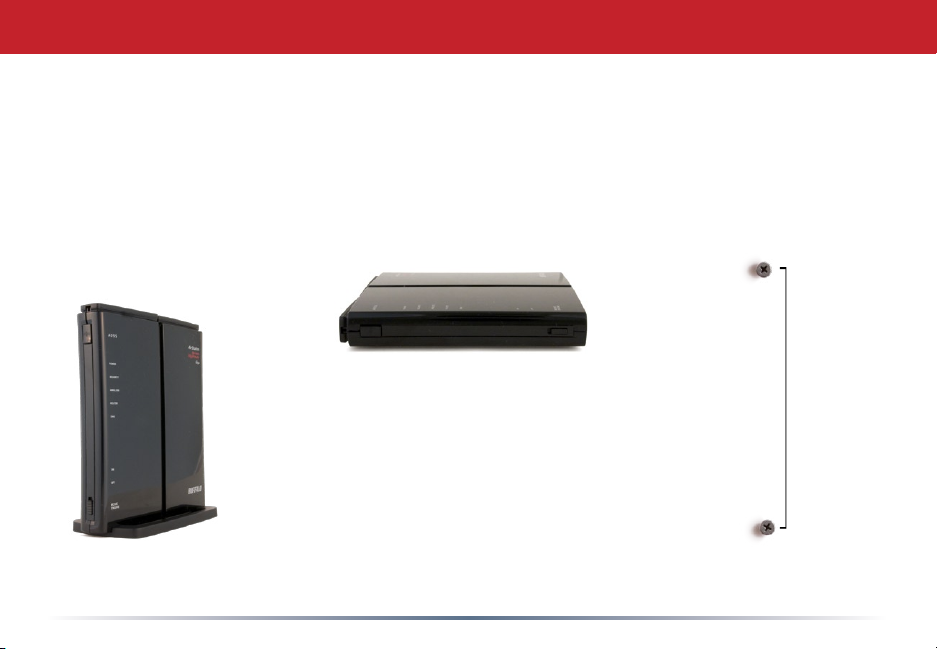
Placing Your AirStation
Your AirStation may be placed horizontally, or vertically with its stand attached. Without
the stand, you can even mount it on the wall.
For wall mounting, screw two of the included wall-mounting screws into the wall as shown
below. With the detachable base removed, slots on the back of the AirStation will t over a
pair of screws in this conguration.
8.6 cm
(~3.3 inches)
5
Page 6
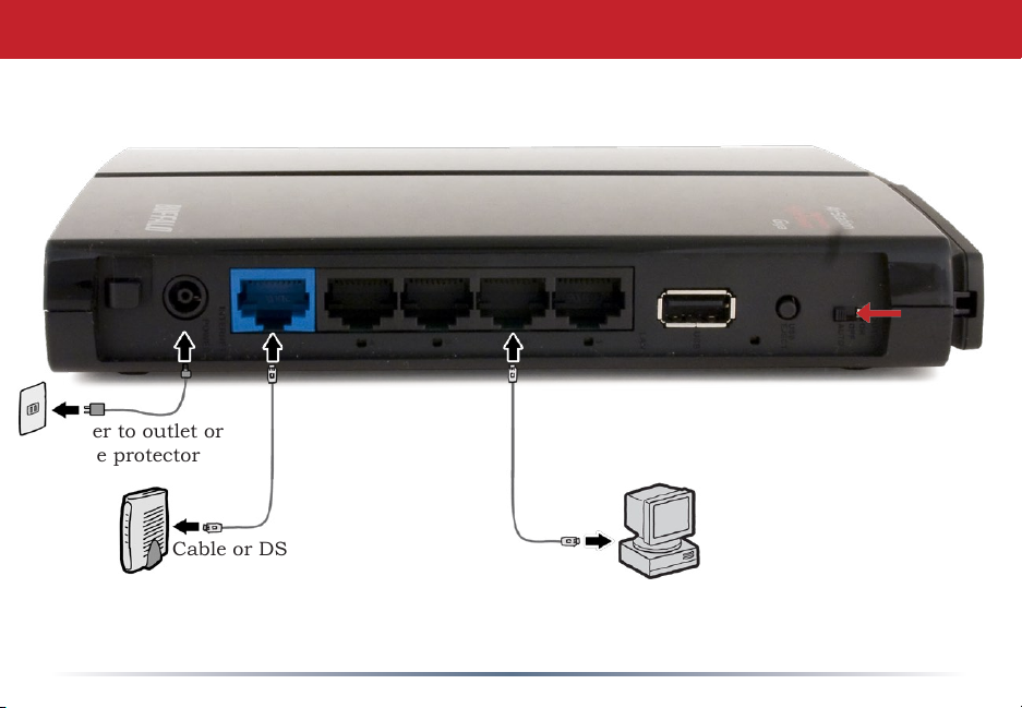
Power to outlet or
surge protector
Connecting your AirStation
Router switch should
be set to Auto for
normal use.
Cable or DSL Modem
PC
6
Page 7
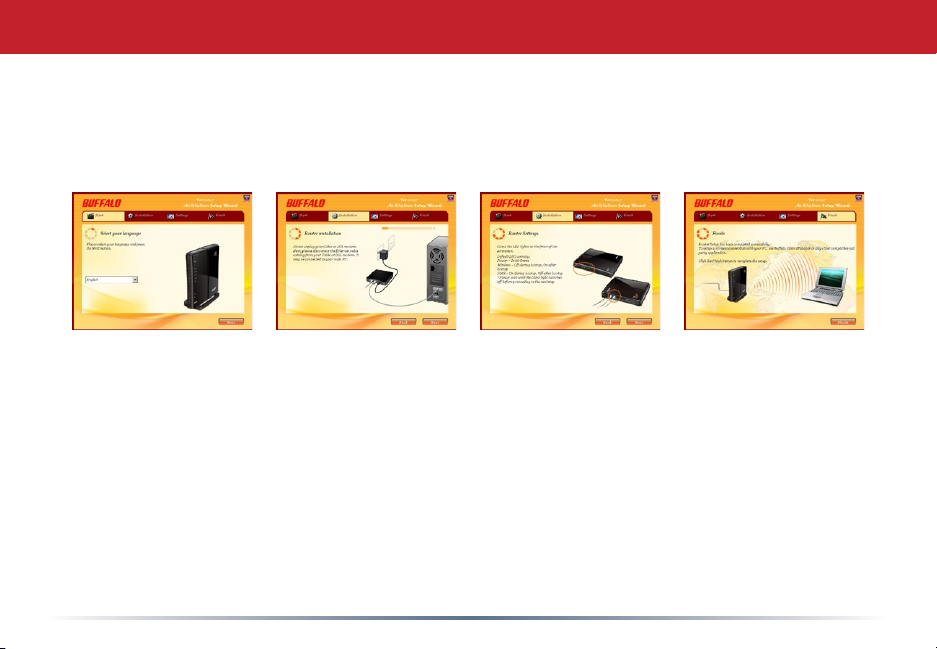
Automatic Installation
The AirNavigator CD can install your AirStation for you automatically. To use the
automatic installation program, insert your AirNavigator CD into your computer and
follow the onscreen directions.
The wizard will guide you through installing your AirStation.
7
Page 8

Manual Installation: Connections
To install the AirStation manually,
1. Power down the Cable or DSL modem and the computer which will be used to
congure the AirStation router.
2. Plug the Cable or DSL modem’s Ethernet cable into the AirStation’s WAN port.
Initially, you may need to unplug this cable from your computer, hub or other router.
3. Plug the provided Ethernet cable into one of the four LAN ports on the AirStation and
plug the other end into your computer’s Ethernet adapter (NIC).
4. Important: turn everything on in the correct order!! Power on your cable or DSL modem
and wait one full minute, then power on the AirStation and wait one full minute, and
nally power on the computer which will be used to congure the AirStation.
8
Page 9

Manual Installation: Log in to the Conguration Tool
Launch a web browser on the computer that you’re
using to congure the AirStation.
Enter 192.168.11.1 into the URL eld. Naturally, if
you change your AirStation’s LAN-side IP address,
you’ll have to enter the new address instead.*
A window will open, prompting you to enter a User ID
and Password.
Enter root as the User name and leave the password
eld blank.
*In AP mode (mode switch Off), the default IP address is 192.168.11.100.
9
Page 10
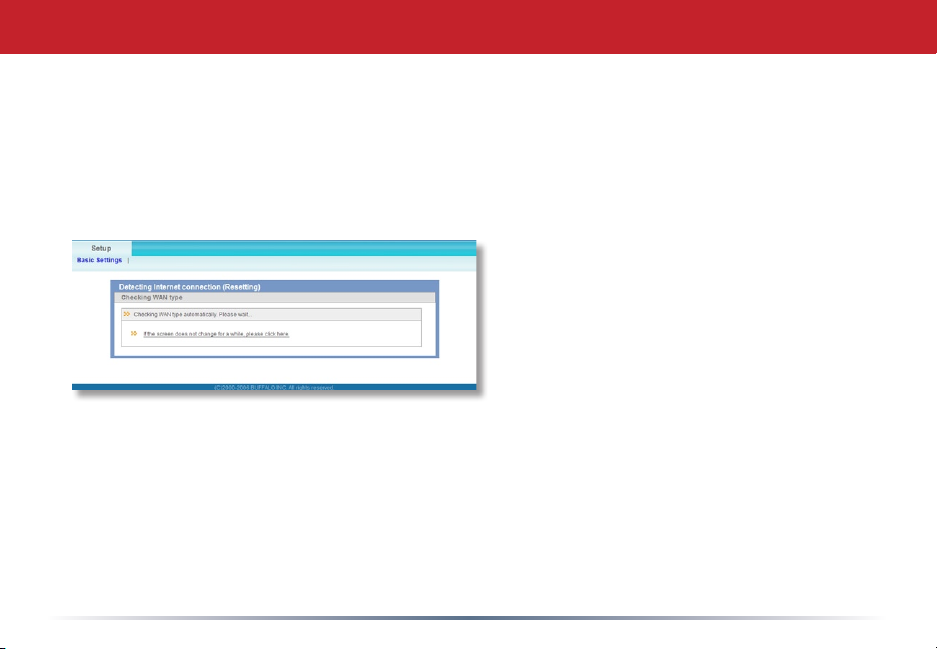
Detecting Your Broadband Connection
Your AirStation’s SmartRouter technology will determine the type of internet
connection you have automatically, and ask you for any needed information. If
your ISP assigns IPs automatically (most cable providers do), their DHCP server
will give your router an IP address. If additional login information is required
to connect to the internet, the wizard will ask for it. Enter any required login
information if asked. Contact your
DSL provider for any missing login
information.
Congratulations! You are now connected to the internet. Open a familiar web
page to make sure everything is working correctly.
10
Page 11
Connecting Wireless Clients to the Access Point
To connect
wireless
devices to the
AirStation, you
may either enter
the SSID and
encryption key
manually, or you
can use AOSS or
WPS.
Consult your
wireless clients’
manuals for
instructions on
conguring them manually. You can get SSID and encryption information from
the AirStation’s Wireless Cong section.
Turn to the next page for instructions on using Windows Zero Cong to connect
Windows computers to the wireless network.
11
Page 12
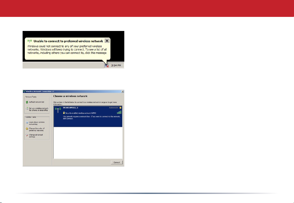
Windows Zero Cong
Each of your wireless clients will need your
password to connect to the network. Click on the
wireless icon in your computer’s systray, or this
message if it pops up.
Any wireless networks available in the area will be
listed as available. Click on your wireless network
SSID so that it turns blue and the click on Connect
at the bottom right.
12
Page 13
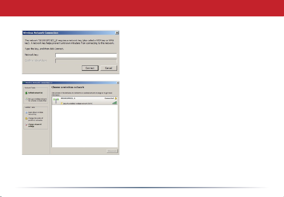
Enter your network key (“password”) twice and click
Connect.
Repeat for each Windows computer that connects to
your network wirelessly.
Other wireless devices may have different conguration requirements. Consult their
documentation for instructions on how to enter your network key and connect them to your
wireless network.
13
Page 14
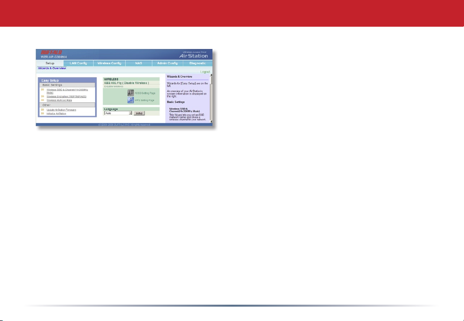
Web Admin Tool
The Setup page is the opening screen of
the Web Admin Tool. From here, you can
change your wireless SSID and channel,
and choose your encryption type under
Basic Settings. The Wireless Cong section
also shows your SSID and encryption
settings.
You can also update your AirStation’s rmware and reset your AirStation to
factory settings. As you explore the conguration tool, you’ll see that context
sensitive help is available on the right side of each page.
14
Page 15
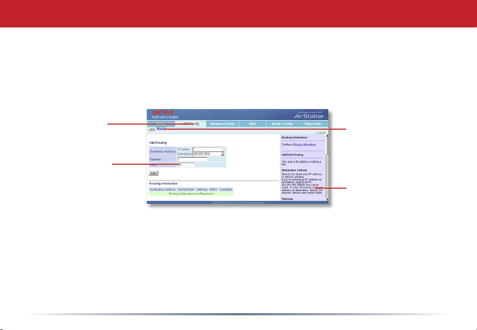
Navigating the Menus
The menus in the Web Admin Tool let you change your AirStation’s settings. To
navigate settings, choose a category at the top of the page and then a submenu
below. Settings will appear on the left, help les on the right. This example
shows the LAN Conguration category with the Route submenu item selected.
Category
Tabs
Individual
Settings
Submenus
Help and
Instructions
15
Page 16
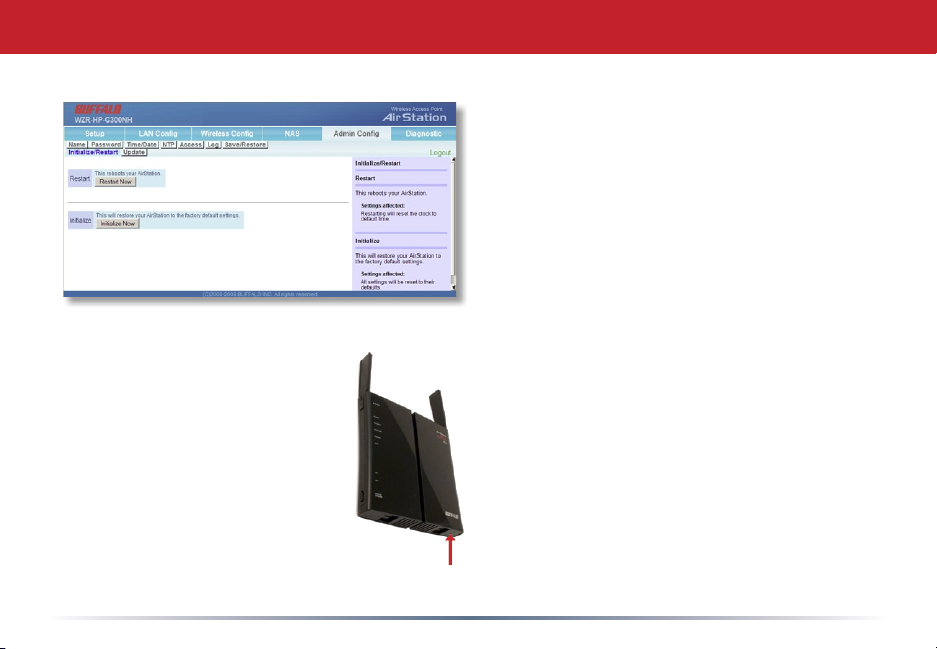
Initialize/Reboot
The Initialize/Restart page can be
reached by choosing the Admin
Cong category tab and then clicking
on the Initialize/Restart submenu.
Click Restart Now from this page
to restart your AirStation. Click
Initialize Now to restore your
AirStation to factory defaults and
restart it.
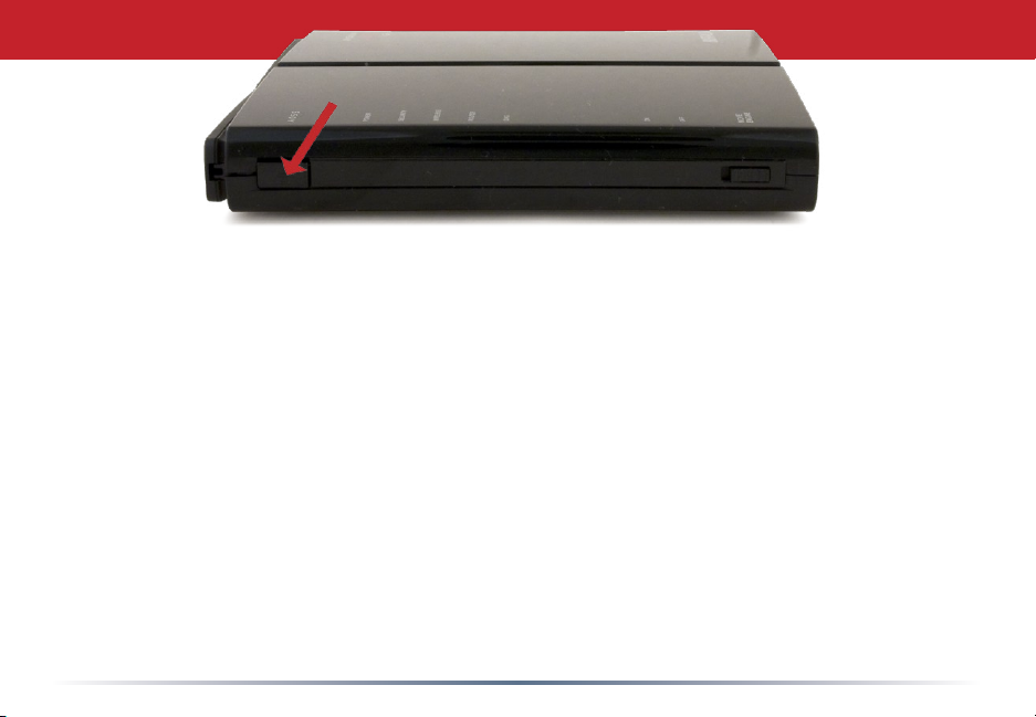
You may also initialize your
AirStation by holding down the Reset
button on the bottom for 3 seconds
with a straightened-out paper-clip or
similar object.
16
Page 17
AOSS
AOSS
AOSS (AirStation One-Touch Secure System) is a simple system for conguring your
wireless network securely. If your router and your client device are installed and both
support AOSS, then making a secure wireless connection between them is very easy.
Push the AOSS button on the front of your router and hold it in for a few seconds. The
AOSS light will begin to ash amber. You now have two minutes to push the AOSS
button on your client device and nish the connection.
An AOSS compatible standalone client device will probably have a little red button labeled
“AOSS” on it. Push the button! About 15 seconds later, you’ll have a secure network
connection.
If your client device is a PC card, CardBus, or PCI adaptor, the AOSS button will
probably be in its Client Manager Software. Check your client device’s user manual for
instructions on where to push or click the AOSS button.
After you’ve pressed both buttons, it will take about 15 seconds for the connection to
complete. When it’s nished, the AOSS light will glow a solid amber. You now have a
secure network connection!
17
Page 18
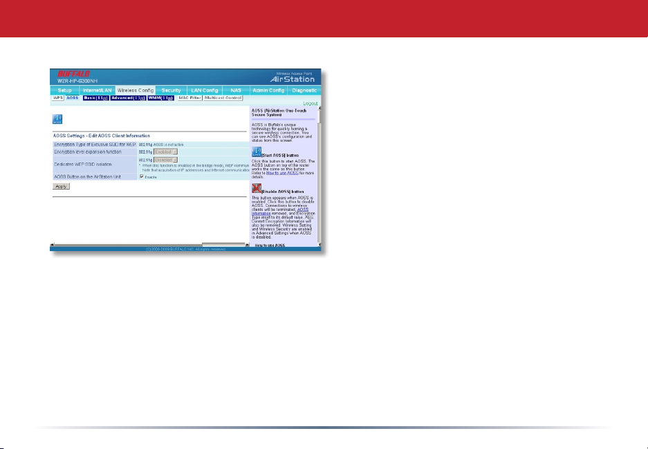
AOSS Advanced Settings
You can get to this page by selecting the
Wireless Cong category and choosing the
AOSS submenu.
The blue AOSS button at the top left of the
page has the same function as the physical
AOSS button on the top of the router: it
initiates the AOSS process.
If all your clients support AOSS, it’s very
simple to set them up. Press the AOSS
button on the router, or the one on this
page, and then push the AOSS button on the
client device. Consult your client device’s
documentation for the location of its AOSS
button.
Each client device should be set up separately. Wait for each AOSS process to nish before
starting the next one.
If you’ve used AOSS to congure some wireless clients, and now want to add other wireless
clients that don’t support AOSS to your network, you’ll need this screen will give you the
information you need to connect them manually.
18
Page 19

If you enable Dedicated WEP SSID Isolation,
then AOSS clients that access the network
via less-secure WEP connections (such
as game devices) will be connected on
an isolated network. They will be able to
communicate with the Internet and each
other, but will not be able to access data on
computers and other clients on the network
that are connected by more secure wireless
encryption techniques.
19
Page 20
AOSS
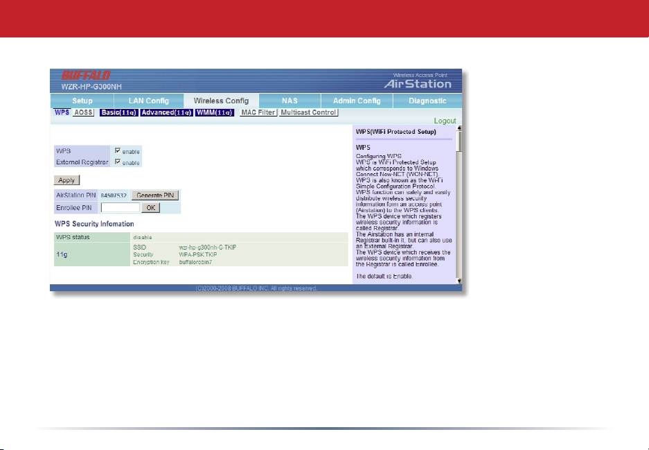
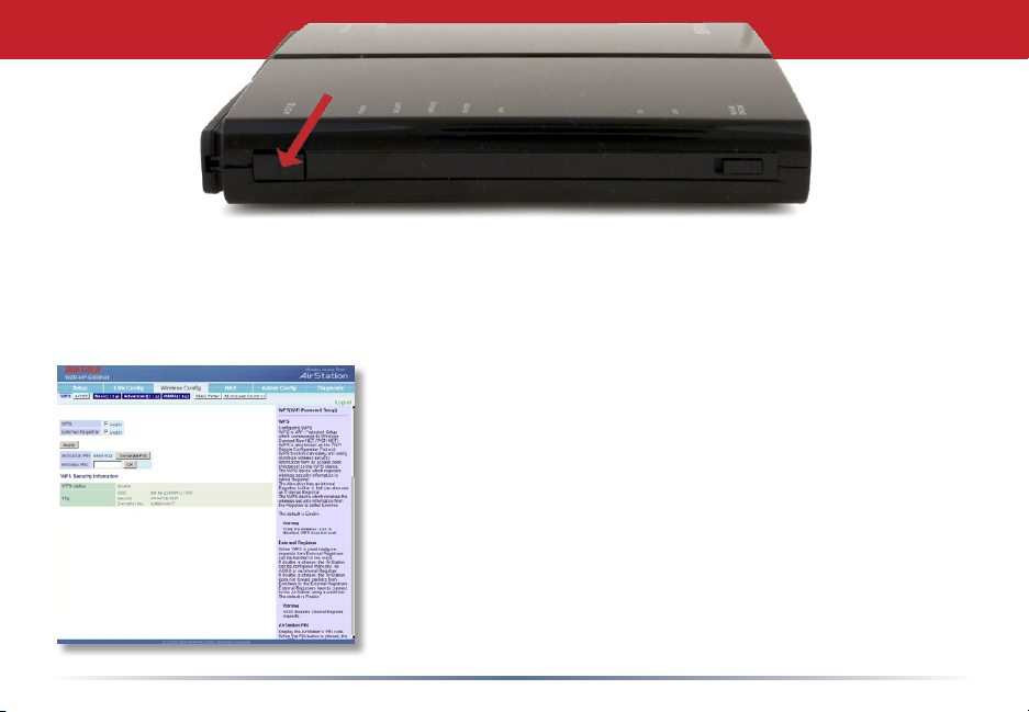
WPS
WPS (Wi-Fi Protected Setup) is a simple system for conguring your wireless network securely.
It’s similar to AOSS, but supported by many brands and types of wireless equipment. Your
wireless clients must support WPS to use this method of setup.
There are three different ways to connect your network devices with WPS.
Method # 1: Within two minutes, push the AOSS/WPS button on your AirStation and then
push the WPS button on your wireless client. WPS will
automatically form a secure wireless connection. Consult
your wireless client’s documentation for the location of its
WPS button.
Method # 2: If your wireless client requests a PIN code, enter
the AirStation’s PIN code. You can get it from the sticker on
the back of the AirStation, or from the WPS page in the Web
Conguration tool.
Method # 3: If your wireless client has a PIN code of its
own, you can enter it into the Enrollee PIN eld on the WPS
conguration page in the AirStation’s Web Cong Tool.
Within minutes, your wireless client will be connected to the
AirStation.
20
Page 21

Automatic Connection
Some things to keep in mind when automatically connecting with
AOSS or WPS:
• Only one wireless client adapter can be congured with AOSS or WPS at a time.
• It is not necessary to reconnect client devices that have already been congured via
AOSS or WPS unless signicant changes have been made to the wireless network.
• Do not attempt to congure two separate AOSS or WPS networks at the same time, as
it may cause undesired congurations.
• If an undesired client has connected via AOSS or WPS, it can be disconnected from
within the WZR-HP-G300NH’s web-based conguration tool.
• Even if your client device doesn’t ofcially support AOSS, you may still be able to use
AOSS if you install Buffalo’s Client Manager software on your computer. It works with
most client devices, including many made by other manufacturers. You can download
it from www.buffalotech.com.
21
Page 22

Movie Engine (QoS) Switch
The Movie Engine feature optimizes multimedia trafc in your network. This feature is also
called “Quality of Service”, often abbreviated to “QoS”. The “Movie Engine” switch on the
front of the AirStation has two positions:
On - With the Movie Engine switch on, the AirStation optimizes the transfer of multimedia
packets. IPv6 passthrough is enabled, the wireless multi-cast rate is increased, and the size
of TCP Rwin is limited. This is ideal for streaming video, audio, and similar multimedia les.
Off - With the Movie Engine switch off, the AirStation acts as a standard router.
The default setting is Off.
22
Page 23

Router/Access Point Mode Switch
The AirStation may be used as either a full wireless router or a simple access point. The
switch has three positions:
On (Router Mode) - The default LAN-side IP address is 192.168.11.1 and DHCP and NAT are
enabled.
Off (AP Mode) - The default LAN-side IP address of the AirStation is 192.168.11.100, and
DHCP and NAT are disabled. The WAN port becomes a fth LAN port.
Auto - The AirStation will attempt to detect another router on the network. If one is
detected, it will switch to AP Mode, but get its IP address from the router’s DHCP. If no
router is detected, then the AirStation will switch to Router Mode. AUTO is the default
setting, and is recommended for most users.
23
Page 24

Encryption and Security
The AirStation supports many types of security and
encryption. During your initial setup, you had the
opportunity to enter a 13 digit encryption key. If you
did, then three SSIDs were set up, and you can now
connect to any of those SSIDs using that encryption
key.
To congure an SSID and encryption key manually,
navigate to Wireless Cong/Basic.
24
Page 25

Encryption and Security
Many kinds of encryption are available. WEP
works with almost everything. WPA2-PSK is
much more secure. Choose the strongest method
of encryption that works with all of your wireless
devices.
If you must use WEP, it is available under “SSID3”.
Check Use to enable WEP.
Enter a “pre-shared key” (password) for this
connection. Passwords should have 8-64
alphanumeric characters. Write down your
password and put it in a safe place. You will not
be able to connect wireless devices to your network
without this password.
25
Page 26

Connecting to an Existing Network
To add an AirStation to a network without changing the existing LAN conguration,
proceed as follows:
1. Set the AirStation to AP mode by moving the switch from AUTO to OFF.
2. Connect one of the AirStation’s LAN ports to an existing router or switch on your
network.
3. Temporarily change your computer’s IP address to an unused address on the
192.168.11.x subnet, with subnet mask 255.255.255.0.
4. Type “192.168.11.100” into a browser window to open the AirStation’s Conguration
Tool.
5. In LAN Cong, congure the following settings:
IP Address = [192.168.1.137] (Specify an unused network address from the existing
LAN.)
Subnet Mask=[255.255.255.0] (Use the same Subnet Mask as the existing LAN.)
6. Restore your PC’s IP address settings to their original values.
Note: While the mode switch is in the OFF position, the AirStation’s WAN port may also
be used as a fth LAN port.
26
Page 27

Setting Up a VPN Server
The AirStation’s VPN server capability lets you
remotely connect to your local network securely
and easily. Even though you may be hundreds
or thousands of miles away, you can still access
servers, printers, and other devices on you local
network as though you were directly connected to
the same router (though somewhat more slowly).
To congure a VPN server on the WZR-HP-G300NH,
navigate to Internet/LAN/VPN Server in the Web
Admin Tool. If you receive an error about your LAN
side IP address being unsuitable for use with VPN
clients, click on the Enter recommended IP address
button. This will move your LAN side IP address
and DHCP address pool to a suitable subnet.
To begin, create one or more user accounts for VPN
by clicking the Edit User Information button.
27
Page 28

Adding Users to a VPN Server
To add a VPN user, enter a User Name and Password
(twice), and click Add User. Repeat for each user
that you want to be able to access the network
remotely.
When nished adding users, click Return to the
Previous Screen.
Make sure that PPTP Server is Enabled and select the
Authorization type that you want to use. Click Apply.
Your VPN server is now ready for use. You can now
connect to the AirStation’s local network remotely
with a VPN client. Many VPN clients are available
that will work with the AirStation. Turn to the next
page for instructions on making a VPN connection
with Windows’ built-in VPN client.
28
Page 29

Remote Connection to the VPN Server
Many VPN clients are available for connecting to the AirStation’s VPN server. In this
example, we’ll use the one built-in to Windows XP. Many other operating systems include
similar VPN clients.
Click Start. Navigate to Network Connections - New
Connection Wizard. Click Next.
Select Connect to the network at my workplace and
click Next.
29
Page 30

Choose Virtual Private Network connection. Click Next.
Choose a name for your VPN connection and click Next.
Select Do not dial the initial connection and click Next.
30
Page 31

Enter the WAN-side IP address of the AirStation.
Click Next.
You can get the AirStation’s WAN-side IP
address from the Internet/LAN - DDNS
section of its Web Admin Tool, where
it is referred to as the “Internet Side IP
Address”.
31
Page 32

Choose whether this connection is to be for your own use only, or
whether to allow anyone using the computer to connect with it.
Click Next.
You may coose whether or not to add a shortcut for this
connection to you desktop. Click Next.
Your VPN connection is ready to use! Enter your username and
password, and click Connect.
Note: Some encryption options may require further
conguration. Consult your operating system’s documentation
for more information on connecting to a VPN server.
32
Page 33

Dynamic DNS
If you have a Dynamic DNS account with DynDNS or TZO, you can let it manage your
AirStation’s hostname for you. Even if your ISP changes your WAN-side IP address, you can
still easily access your network by its dynamically congured hostname. This is particularly
useful if you are using the AirStation
as a VPN server with a non-static IP
address.
To congure Dynamic DNS, navigate to
Internet/LAN - DDNS in the Web Admin
Tool and choose your Dynamic DNS
Service. Enter any necessary login
information and click Apply.
33
Page 34

Connecting USB Devices
To add a USB hard drive or ash drive to the AirStation, plug it in to the AirStation’s USB
port.
USB devices with FAT or XFS formats are supported.
In the Web Cong Tool, select the NAS tab.
34
Page 35

In NAS/Shared service, put a check next to
Use to enable shared folder functionality.
Click Apply.
Connecting USB Devices
Before sharing the hard drive, you must
add at least one user. Navigate to NAS/
User Management and enter a user name
and password. Click Add. The new user
will appear at the bottom of the page under
User Information.
35
Page 36

Connecting USB Devices
Navigate to NAS/Shared folder. Choose a name for the shared folder. For normal use on
your local network, check Samba. To be able to access the share from outside your local
network, check Web access. To use this share as the destination for your downloaded
BitTorrent les, check BitTorrent. Use the arrow buttons to give read-write or read-only
access to users. Click Add when done.
Note: Only one shared folder may be set as the destination folder for downloaded
BitTorrents. Disable BitTorrent in any previously created shares before enabling it for a
new one.
36
Page 37

Accessing Shares on your USB Device
Now that your USB hard drive is congured, you may access it from anywhere on your
local network. For ease of use, map a driveletter to the NAS share. Then, you can treat
the shared drive just like any other drive on the PC.
From your Windows PC, open Network Neighborhood. Click
on Tools, then Map Network Drive.
Chose the drive letter that you want to map to the share.
Click the Browse... button.
37
Page 38

Accessing Shares on your USB Device
Browse to the new share. It will be located at Network/
Entire Network/Microsoft Windows Network/Workgroup/
ApMACaddress/share, where MACaddress is the MAC address
of the AirStation and share is the name of the shared folder on
the drive attached to the AirStation. Click OK.
Click Finish to map the driveletter. In this example, Z: is being
mapped to the network drive.
Your shared drive is now available for use.
38
Page 39

Disconnecting USB Devices
To release the USB device, hold down the USB Release button for 3 seconds. The USB
device will be dismounted. When the USB LED stops blinking, it is safe to unplug the
USB drive.
Note: Unplugging USB devices without properly dismounting them rst may result in
loss or corruption of data.
39
Page 40

WebAccess
If you checked WebAccess when
you were setting up your share on
page 28, then you can congure
your share so that you can access it
from outside of your local network.
To turn on WebAccess, navigate to
NAS/Web Access and check the Use
box.
You may enable encryption if
desired.
If checked, Auto-congure Firewall
will congure your router for you.
Otherwise, you will need to manually
forward internal port 9000 to the
Internet.
Choose a name for your BuffaloNAS account and a password (“key”). This name is the
name that will be used to access your data. The password for this protects your data from
being accessed by unauthorized people, so picking a strong password is recommended.
Click Apply when done.
40
Page 41

To access your share remotely with WebAccess, open a
browser window on any computer connected to the Internet
and go to buffalonas.com.
In the dialog box, type the BuffaloNAS name that you set on
the previous page.
Alternately, you can go directly to your share by typing
BuffaloNAS.com/your_BuffaloNAS_name in the URL window.
The folders from your share will appear. Files from anonymous
shares will appear to the right. To see les from shares that
are not set to anonymous, or to upload les, you will need to
log in. The ‘login’ link is on the top left corner of the page.
Using WebAccess
41
Page 42

Clicking on individual les will give you other
options, depending on the letype. Clicking
on the Audio link at the bottom left corner of
the page will give you options for playing music
les, including the opportunity to launch a
Flash-based music player that will stream your
audio les directly through the Web interface.
Using WebAccess
To access individual folders on the right, click
on their open links.
42
Page 43

Using WebAccess (Uploading Files)
To upload les, click Upload in the bottom left corner of the
window. Note: This option will not appear unless you are
logged in and at least one user (besides admin) has been
given access to the share.
This window will pop up. Click on Browse and
navigate to the le that you want to upload.
Then, click Upload.
The le uploads.
Once the upload is complete, the le is available for use.
43
Page 44

Click Apply when done, then click Download Manager.
BitTorrent
If you checked BitTorrent
when you were setting up
your share on page 28, then
you can use the AirStation’s
built-in BitTorrent client
to download your les for
you. To turn on BitTorrent
functionality, navigate to
NAS/BitTorrent and check
the Enable box.
You may specify the port
used for downloads if
desired.
Bandwidth restrictions may
be modied or disabled if
desired.
44
Page 45

BitTorrent (Download Manager)
Once a download is complete, the le will be available
in your shared folder. Double-click on the mapped
drive in My Computer to access it.
Note: Instructions for mapping a driveletter to your
shared folder are on pages 29 and 30.
To add torrents, Browse to them
and then click Add. The le(s)
will automatically download in
the background. Buttons to the
right of each torrent allow you to
terminate the download or delete
the torrent.
45
Page 46

Specications
WZR-HP-G300NH AirStation Specications
Wireless LAN
Standards: IEEE 802.11n Draft 2.0, IEEE 802.11g, IEEE 802.11b
Frequency Range: 2.412-2.462
2 External and 1 Internal Antennas
Security: WPA2-PSK, WPA-PSK, WEP, MAC Address Registration
Wired LAN
Standards: IEEE 802.3ab, IEEE 802.3u, IEEE 802.3
(4) 10/100/1000 Mbps RJ-45 auto-sensing Ethernet ports
(1) 10/100/1000 Mbps RJ-45 WAN port with DPF and NAT/SPI rewall
Temperature & Humidity
Operation 32˚ - 104˚ F, 0˚ - 40˚ C
Maximum humidity 80%
Power Characteristics
Power Supply: 100 - 240V AC Universal, 50/60 Hz.
Power Output: 12V DC
Power Consumption about 24 Watts (Max)
46
Page 47

Specications
Regulatory Information
Wireless communication is often subject to local radio regulations. Although AirStation
wireless networking products have been designed for operation in the license-free 2.4 GHz
band, local radio regulations may impose limitations on the use of wireless communication
equipment.
Network Compatibility
Draft-N support built off of the Draft Specication 3.0 for 802.11n.
IEEE802.11g/b Standard for Wireless LANs.
Host Operating System
Microsoft Windows® 98SE/ME/2000/XP/Vista 32bit, and Mac OS X 10.4x and later
47
Page 48

Troubleshooting
Common Problems
• Out of range, client cannot connect to the AirStation.
• Conguration mismatch, client cannot connect to the AirStation.
• Absence or conict with the Client Driver.
• Conict of another device with the AirStation hardware.
LED Activity
Monitoring LED activity may help identify problems.
• Power LED should be Green when the AirStation is on.
• The Security LED lights when encryption or authorization is turned on.
• Wireless LED should be Green if the line is active. If it is blinking Green, wireless
communication is active.
• Router LED should be Green in Router Mode. It will be off if the AirStation is in AP or
Auto modes.
• The Red Diag LED will ash during boot and rmware updates. 3 red ashes at boot
indicates a problem with the wired LAN side. 4 red ashes at boot indicates a problem
with the wireless LAN side.
To check the Diag LED, unplug the power for three seconds. Plug the power back in and
watch the Diag LED during boot-up.
48
Page 49

Troubleshooting
LEDs Work But Client PC Cannot Connect to Network
If the LEDs indicate that the network is working properly (Power LED is on, Transmit/
Receive LED blinks), check the TCP/IP settings of the network.
Changing Client TCP/IP Settings in Windows
Consult the LAN Administrator for correct TCP/IP settings.
To add or change TCP/IP Settings:
1. On the Windows task bar, click Start.
2. Select Settings, then Control Panel.
3. Double-click on the Network icon to view Network Properties.
4. From the list of installed components, verify the “TCP/IP - wireless LAN adapter”
protocol is installed.
• If the wireless adapter protocol is not yet installed, click the Add button and select
the TCP/IP protocol from the list. Refer to Windows Help for more information.
• If the wireless adapter protocol is installed, select the protocol and click the
Properties button. Verify that the parameters match the settings provided by your
LAN Administrator. Make changes if necessary, and click OK.
5. If prompted, restart your computer.
Other Problems
Please refer to www.buffalotech.com for further reference materials.
49
Page 50

Glossary
10BaseT: 802.3 based Ethernet network
that uses UTP (Unshielded twisted pair)
cable and a star topology. 10 Mbps data
transmission speed.
100BaseT: 802.3 based Ethernet network
that uses UTP (Unshielded twisted pair)
cable and a star topology. 100 Mbps data
transmission speed.
1000BaseT: 802.3 based Ethernet
network that uses UTP (Unshielded twisted
pair) cable and a star topology. 1000 Mbps
data transmission speed.
802.1x: The standard for wireless LAN
authentication used between an AP and a
client. 802.1x with EAP will initiate key
handling.
Access Point: A hardware device that acts
as a communication hub for Clients (users
of wireless devices) to connect to a wired
LAN.
Bandwidth: The transmission capacity of
a computer or a communication channel,
usually stated in Megabits per second
(Mbps).
Bridge: A device which forwards trafc
between network segments with a common
network layer address, based on data link
layer information.
Client: A PC, workstation, or other device
that connects to a network wirelessly
through an Access Point.
Cross-Over Cable: A UTP cable that has its
transmit and receive pair crossed to allow
communications between two devices.
Default Gateway: The IP Address of either
the nearest router or server for the LAN.
Destination Address: The address portion
of a packet that identies the intended
recipient station.
50
Page 51

Glossary
DHCP (Dynamic Host Conguration
Protocol): Based on BOOTP, it uses a pool
of IP addresses, which it assigns to each
device connected to it, and retrieves the
address when the device becomes dormant
for a period of time.
DNS (Domain Name System): System
used to map readable machine names into
IP addresses.
Driver: Software that interfaces a
computer with a specic hardware device.
Dynamic IP Address: An IP address that
is automatically assigned to a client station
in a TCP/IP network, typically by a DHCP
server.
Ethernet: The most widely used
architecture for Local Area Networks
(LANs). It is a shared-media network
architecture. The IEEE 802.3 standard
details its functionality.
Ethernet cable: A wire similar to telephone
cable that carries signals between Ethernet
devices. It is designed to connect a single
device’s NIC to a router, switch, or hub.
See also Crossover cable.
File and Print Sharing: A Microsoft
application that allows computers on a
network to share les and printers.
Firmware: Computer programming
instructions that are stored in a readonly memory unit rather than being
implemented through software.
Frame: A xed block of data, transmitted
as a single entity. Also referred to as a
packet.
Full-Duplex: To transmit in both
directions simultaneously.
Half-duplex: To transmit in both
directions, one direction at a time.
51
Page 52

Glossary
Hub: A device which allows connection
of computers and other devices to form a
LAN.
IEEE (Institute of Electrical and
Electronics Engineers): The professional
organization which promotes development
of electronics technology.
IP (Internet Protocol) Address: A unique
32-binary-digit number that identies each
sender or receiver of information sent in
packets.
Infrastructure: A wireless network or
other small network in which the wireless
network devices are made a part of the
network through the Access Point.
ISP (Internet Service Provider): A
company that provides access to the
Internet and other related services.
IV (Initialization Vector): The header
section of an encrypted message packet.
LAN (Local Area Network): A group
of computers and peripheral devices
connected to share resources.
LED (Light Emitting Diode): The lights
on a hardware device representing the
activity through the ports.
MAC (Medium Access Control) Address:
The unique number that distinguishes
every network interface card.
Mbps (Mega Bits Per Second): A
measurement of millions of bits per
second.
MDI/X (Media Dependent Interface/
Cross-over): Port on a network hub or
switch that crosses the incoming transmit
lines with the outgoing receive lines.
MHz (MegaHertz): One million cycles per
second.
52
Page 53

Glossary
NAT (Network Address Translation): An
internet standard that enables a LAN to
use one set of IP addresses for internal
trafc and a second set for external trafc.
NIC (Network Interface Card): An
expansion card connected to a computer
so the computer can be connected to a
network.
Packet: A block of data that is transferred
as a single unit, also called a frame or a
block.
Packet Filtering: Discarding unwanted
network trafc based on its originating
address or its type.
PCMCIA (Personal Computer Memory
Card International Association) Card:
Removable module that adds features to a
portable computer.
Ping (Packet Internet Groper): An
Internet utility used to determine whether
a particular IP address is accessible.
Plug and Play: Hardware that, once physically
installed, nishes its installation automatically
and may immediately be used, as opposed
to hardware that requires further manual
conguration.
PoE (Power over Ethernet): A mechanism to
send DC power to a device along its Ethernet
cable.
PPPoE (Point-to-Point Protocol over
Ethernet): A specication for connecting users
on an Ethernet line to the Internet through a
common broadband medium.
Protocol: A standard way of exchanging
information between computers.
RADIUS (Remote Authentication Dial
In User Service): A server that issues
authentication keys to clients.
RAM (Random Access Memory): Nonpermanent memory.
53
Page 54

Glossary
RJ-45 connector: An 8-pin connector
used between a twisted pair cable and a
data transmission device.
ROM (Read Only Memory): Memory
hardware that allows fast access to
permanently stored data but prevents
addition to or modication of the data.
Roaming: The ability to use a wireless
device while moving from one access point
to another without losing the connection.
SMTP (Simple Mail Transfer Protocol):
The protocol used to dene and deliver
electronic mail (E-mail) from one location
to another.
SNMP (Simple Network Management
Protocol: An application layer protocol
that outlines the formal structure for
communication among network devices.
Static IP Address: A permanent IP
address assigned to a node in a TCP/IP
network.
SSID: The “name” of your wireless
network. You can get it from the Setup
page of the conguration utility.
STP (Shielded Twisted Pair): Twisted Pair
cable wrapped in a metal sheath to provide
extra protection from external interfering
signals.
Subnet Mask: An eight-byte address
divided into 4 parts separated by periods.
TCP/IP (Transmission Control Protocol/
Internet Protocol: Protocol used by
computers when communicating across
the Internet or Intranet.
TKIP (Temporal Key Integrity Protocol):
An encryption method replacing WEP.
TKIP uses random IV and frequent key
exchanges.
Twisted Pair: Cable that comprises 2
or more pair of insulated wires twisted
together.
54
Page 55

Glossary
UDP (User Datagram Protocol): A
communication method (protocol)
that offers a limited amount of service
when messages are exchanged between
computers in a network. UDP is used as
an alternative to TCP/IP.
UTP (Unshielded Twisted Pair) cable:
Two or more unshielded wires twisted
together to form a cable.
WAN (Wide Area Network): A networking
system covering a wide geographical area.
WEP Encryption: A common security
protocol for wireless networks. WEP is
compatible with almost all wireless devices.
Web Browser: A software program that
allows viewing of web pages.
Wi-Fi (Wireless Fidelity): An organization
that tests and assures interoperability
among WLAN devices.
WLAN (Wireless LAN): A LAN topology
using wireless devices.
WPA Encryption: An encryption algorithm
designed to improve on the security of
WEP.
WPA2 Encryption: An advanced AESbased encryption algorithm. This is the
latest, best security algorithm currently
available for Buffalo Wi-Fi products.
VPN (Virtual Private Network): A security
method to connect remote users to a LAN.
55
Page 56

FCC / CE Information
Federal Communication Commission Interference Statement
This equipment has been tested and found to comply with the limits for a Class B digital
device, pursuant to Part 15 of the FCC Rules. These limits are designed to provide reasonable
protection against harmful interference in a residential installation. This equipment
generates, uses and can radiate radio frequency energy and, if not installed and used in
accordance with the instructions, may cause harmful interference to radio communications.
However, there is no guarantee that interference will not occur in a particular installation.
If this equipment does cause harmful interference to radio or television reception, which
can be determined by turning the equipment off and on, the user is encouraged to try to
correct the interference by one of the following measures:
• Reorient or relocate the receiving antenna.
• Increase the separation between the equipment and receiver.
• Connect the equipment into an outlet on a circuit different from that to which the receiver
is connected.
• Consult the dealer or an experienced radio/TV technician for help.
FCC Caution:
Any changes or modifications not expressly approved by the party responsible for compliance
could void the user’s authority to operate the equipment.
56
Page 57

FCC / CE Information
This device complies with Part 15 of the FCC Rules. Operation is subject to the following two
conditions: (1) This device may not cause harmful interference, and (2) this device must accept
any interference received, including interference that may cause undesired operation.
Important Note - FCC Radiation Exposure Statement:
This equipment complies with FCC radiation exposure limits set forth for uncontrolled
equipment. This equipment should be installed and operated with minimum distance 20cm
between the radiator and your body.
This transmitter must not be co-located or operating in conjunction with any other antenna
or transmitter.
The availability of some specific channels and/or operational frequency bands are country
dependent and are firmware programmed at the factory to match the intended destination.
The firmware setting is not accessible by the end user.
Industry Canada statement:
This device complies with RSS-210 of the Industry Canada Rules. Operation is subject to
the following two conditions:
(1) This device may not cause harmful interference, and (2) this device must accept any
interference received, including interference that may cause undesired operation.
57
Page 58

Important Note - Radiation Exposure Statement:
This equipment complies with IC radiation exposure limits set forth for an uncontrolled
environment. This equipment should be installed and operated with minimum distance 20cm
between the radiator & your body.
European Union Notice:
Radio products with the CE marking comply with the R&TTE Directive (1999/5/EC), the
EMC Directive (89/336/EEC) and the Low Voltage Directive (73/23/EEC) issued by the
Commission of the European Community.
Compliance with these directives implies conformity to the following European Norms:
• EN 60950 Product Safety
• EN 300 328 Technical requirement for radio equipment
• EN 301 489-1/-17 General EMC requirements for radio equipment
Taiwan:
SAR compliance has been established in typical laptop computer(s) with CardBus
slot, and product could be used in typical laptop computer with CardBus slot. Other
application like handheld PC or similar device has not been veried, may not comply with
related RF exposure rules, and such use shall be prohibited.
58
Page 59

Safety
This equipment is designed with the utmost care for the safety of those who install and
use it. However, special attention must be paid to the dangers of electric shock and static
electricity when working with electrical equipment. All guidelines of this manual and of
the computer manufacturer must therefore be allowed at all times to ensure the safe use
of the equipment.
Intended use
This device is a 2.4 GHz wireless LAN transceiver, intended for indoor home and ofce
use in USA, Canada, all EU and EFTA member states.
EU Countries intended for use
This device is intended for indoor home and ofce use in the following countries: Austria,
Belgium, Denmark, France, Finland, Germany, Greece, Italy, Ireland, Luxembourg,
The Netherlands, Portugal, Spain, Sweden, United Kingdom, Cyprus, Czech Republic,
Estonia, Hungry, Latvia, Lithuania, Malta, Poland, Slovak Republic, and Slovenia.
The device is also authorized for use in all EFTA member states Iceland, Liechtenstein,
Norway and Switzerland.
EU countries not intended for use
None
59
Page 60

Potential restrictive use
This device is a 2.4 GHz wireless LAN transceiver, intended for indoor home and ofce
use in all EU and EFTA member states, except in France, Belgium and Italy where
restrictive use applies.
In Italy the end-user should apply for a license at the national spectrum authorities in
order to obtain an authorization to use the device for setting up outdoor radio links.
In Belgium there is a restriction in outdoor use. The frequency range in which outdoor
operation in Belgium is permitted is 2460 – 2483.5 MHz.
In France only channels 10,11,12 and 13 are available.
This device may not be used for setting up outdoor radio links in France. For more
information see http://www.anfr.fr/ and/or http://www.art-telecom.fr
60
Page 61

Environmental Information
• The equipment that you have purchased has required the extraction and use of natural
resources for its production.
• The equipment may contain hazardous substances that could impact health and the
environment.
• In order to avoid the dissemination of those substances in our environment and to diminish the
pressure on the natural resources, we encourage you to use the appropriate take-back systems.
• The take-back systems will reuse or recycle most of the materials of your end life equipment in
a sound way.
• The crossed-out wheeled bin symbol invites you to use those systems.
• If you need more information on the collection, reuse and recycling systems, please contact
your local or regional waste administration.
61
Page 62

Warranty Information
Buffalo Technology (Melco Inc.) products come with a two-year limited warranty from the
date of purchase. Buffalo Technology (Melco Inc.) warrants to the original purchaser the
product; good operating condition for the warranty period. This warranty does not include
non-Buffalo Technology (Melco Inc.) installed components. If the Buffalo product malfunctions
during the warranty period, Buffalo Technology/(Melco Inc.) will replace the unit, provided
the unit has not been subjected to misuse, abuse, or non-Buffalo Technology/(Melco Inc.)
authorized alteration, modications or repair.
All expressed and implied warranties for the Buffalo Technology (Melco Inc) product line
including, but not limited to, the warranties of merchantability and tness of a particular
purpose are limited in duration to the above period.
Under no circumstances shall Buffalo Technology/(Melco Inc.) be liable in any way to the
user for damages, including any lost prots, lost savings or other incidental or consequential
damages arising out of the use of, or inability to use the Buffalo products.
In no event shall Buffalo Technology/(Melco Inc.) liability exceed the price paid for the product
from direct, indirect, special, incidental, or consequential damages resulting from the use of
the product, its accompanying software, or its documentation. Buffalo Technology (Melco
Inc.) does not offer refunds for any product.
@ 2003-2009 Buffalo Technology (Melco, Inc.)
62
Page 63

Contact Information (North America)
Buffalo Technology USA Inc.
11100 Metric Blvd, Suite 750
Austin, TX 78758
GENERAL INQUIRIES
Monday through Friday
8:30am-5:30pm CST
Direct: 512-794-8533 | Toll-free: 800-456-9799 | Fax: 512-794-8520 | Email: sales@
buffalotech.com
TECHNICAL SUPPORT
North American Technical Support by phone is available 24 hours a day, 7 days a week. (USA
and Canada).
Toll-free: (866) 752-6210 | Email: info@buffalotech.com
63
Page 64

Contact Information (Europe)
Buffalo Technology UK Ltd.
2 Bracknell Beeches, Old Bracknell Lane
Bracknell, Berkshire, RG12 7BW
United Kingdom
GENERAL INQUIRIES
Email: sales@buffalo-technology.com
TECHNICAL SUPPORT
Buffalo Technology provides technical support in English, German, French, Italian, and
Spanish. For opening hours and relevant telephone numbers, please go to
www.buffalo-technology.com/contact
64
Page 65

GPL Source Code
Source code for Buffalo products that use GPL code is available at http://opensource.buffalo.jp.
65
Page 66

300* High Speed Mode
*300 Mbps is the link speed when using Wireless-N mode. It represents
actual wireless data speeds, including overhead. Because the overhead
is not available for user data transfer, usable wireless throughput will be
substantially slower.
66
 Loading...