

Page 1

2004 BUELL LIGHTNING
SERVICE MANUAL
Part Number 99490-04Y
Section 1: Maintenance
Section 2: Chassis
Section 3: Engine
Section 4: Fuel System
Section 5: Starter
Section 6: Drive/Transmission
Section 7: Electrical
Appendices
Page 2
HOME
APPENDIX A–TOOLS
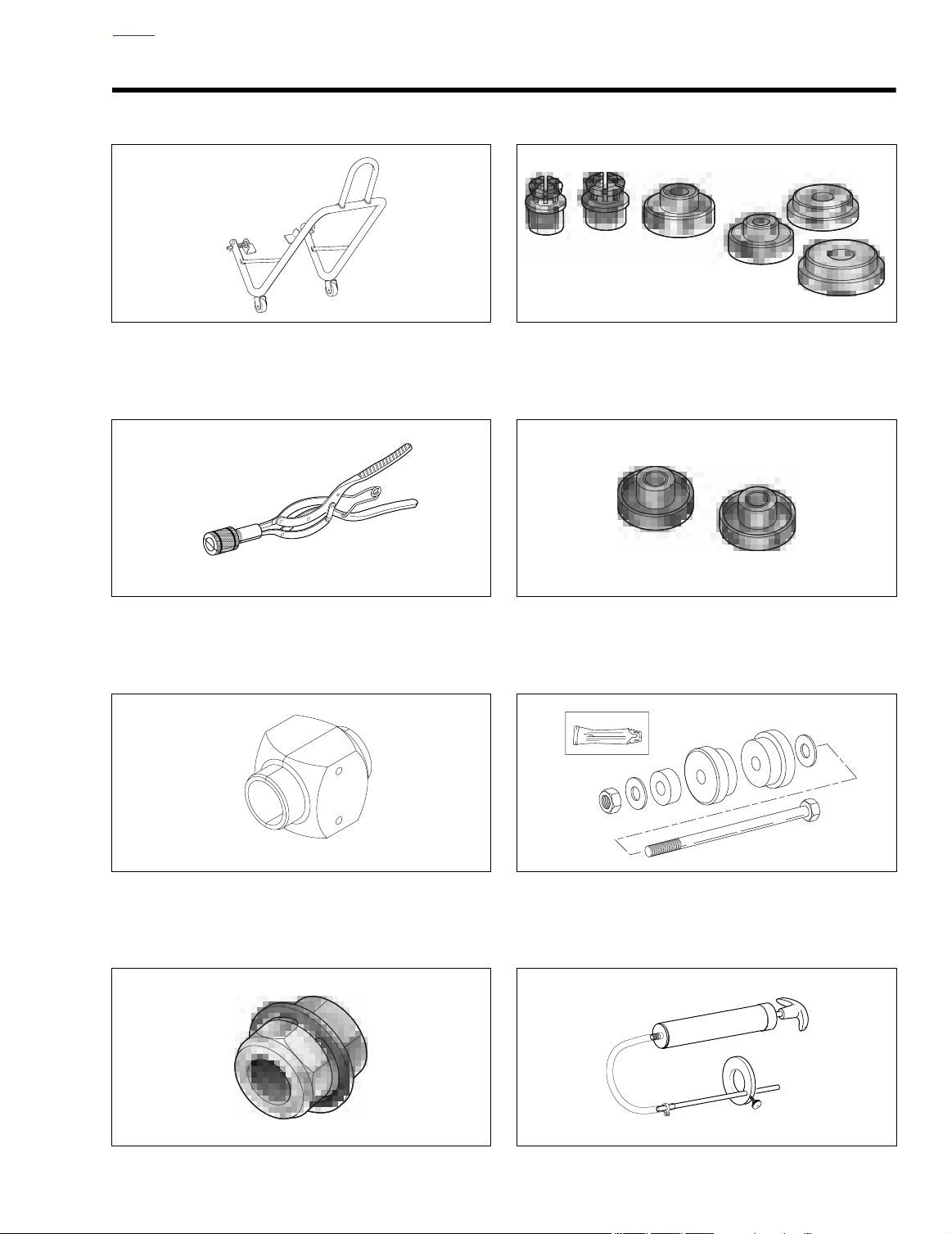
Part No. B-41174 Rear Wheel Support Stand and
Part No. B-41174-2 Replacement Pad
Part No. B-42887 Brake Caliper Piston Remover
Part No. B-43993-7/-8 Wheel Bearing Collets
Part No. B-45521 Steering Head Bearing Remover/
Installer
Part No. B-43721 Front Fork Seal Driver
Part No. B-46279 7/8" Axle Wrench (Hex)
Part No. HD-39302 Steering Head Bearing Race Installer
(Used with B-45521)
Part No. B-59000B Pro Level Oil Gauge
Appendix A A-1
Page 3
HOME
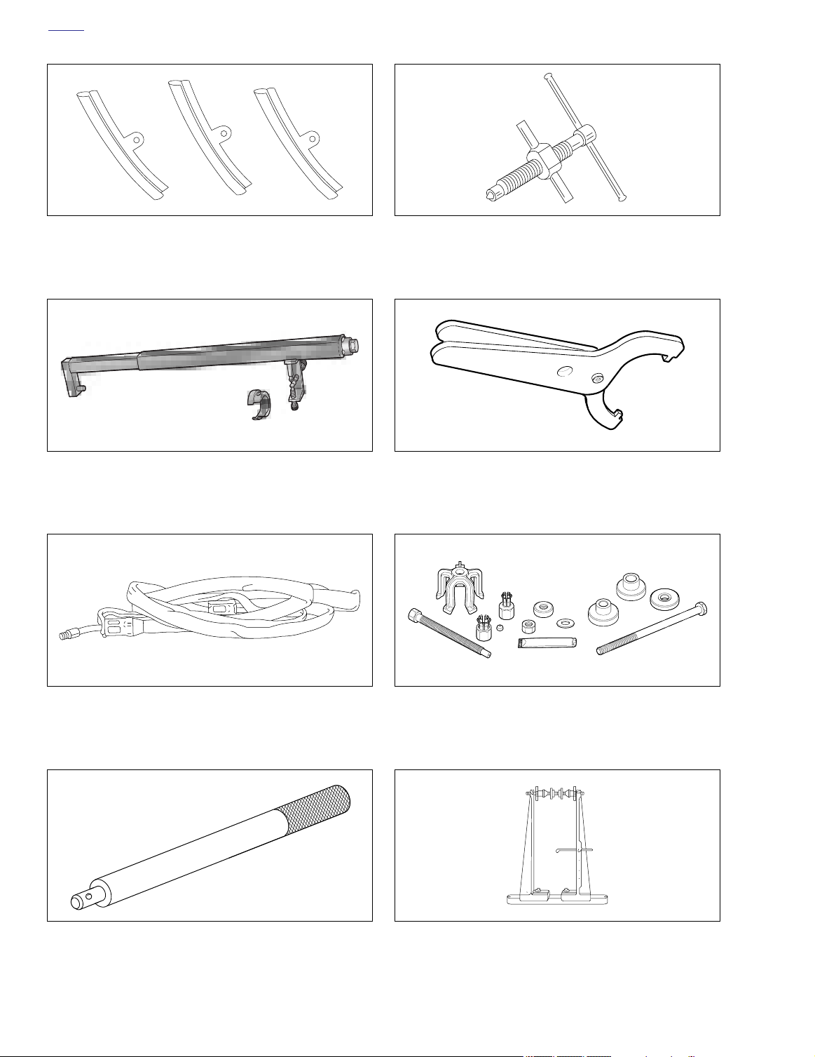
Part No. HD-01289 Rim Protectors
Part No. HD-45966 Fork Spring Compressing Tool
Part No. HD-33418 Universal Puller Forcing Screw
Part No. HD-94700-52C Shock Spanner Preload
Adjustment Tool
Part No. HD-28700 Tire Bead Expander
Part No. HD-33416 Universal Driver Handle
A-2 Appendix A
Part No. HD-44060 Wheel Bearing Remover/Installer
Part No. HD-99500-80 Wheel Truing
and Balancing Stand
Page 4
HOME
CYLINDER LEAKDOWN TESTER
JHYUY
Guibikhf iugu iu ptr td6rd
Foihjolm oijfollkop Yuooifoihfm
knsdl hlno hslnslnnsdl hlno
bs npond bpdk kznh
odlbndpob npond bndb n
CYLINDER LEAKDOWN TESTER
Bdhgkjsbkdv ' ksjjlkn lk
knsdl hlno hslnsln nlslns finbp pffb
odlbndpob nponno[bho
knsdl hlno hslnsln nlslns finbp pffb
odlbndpob npdb ndbno[bho
knsdl hlno hslnslnnsdl hlno hso[bho
knsdl hlno hslnslp pffb
odlbndpob npond bndb ndbno[bho
Bdhgkjsbkdv ' ksjjlkn lk
knsdl hlno hslnsln nlslns finbp pffb
odlbndpob nponno[bho
knsdl hlno hslnsln nlslns finbp pklhb
odlbndpob npdb ndbno[bho
knsdl hlno hslnslnnsdl hlno hso[bho
bs npond bpdk kznh
odlbndpob npond bndb ndbno[bho
Bdhgkjsbkdv ' ksjjlkn lk
knsdl hlno hslnsln nlslns finbp pffb
odlbndpob nponno[bho
knsdl hlno hslnsln nlslns finbp pklhb
Bdhgkjsbkdv Majjlkn Nolk
knsdl hlno hslnsln
ndpob npond
Bdhgkjsbkdv hlno hslnslp
knsdl hlno hslnsln
ndpob npond
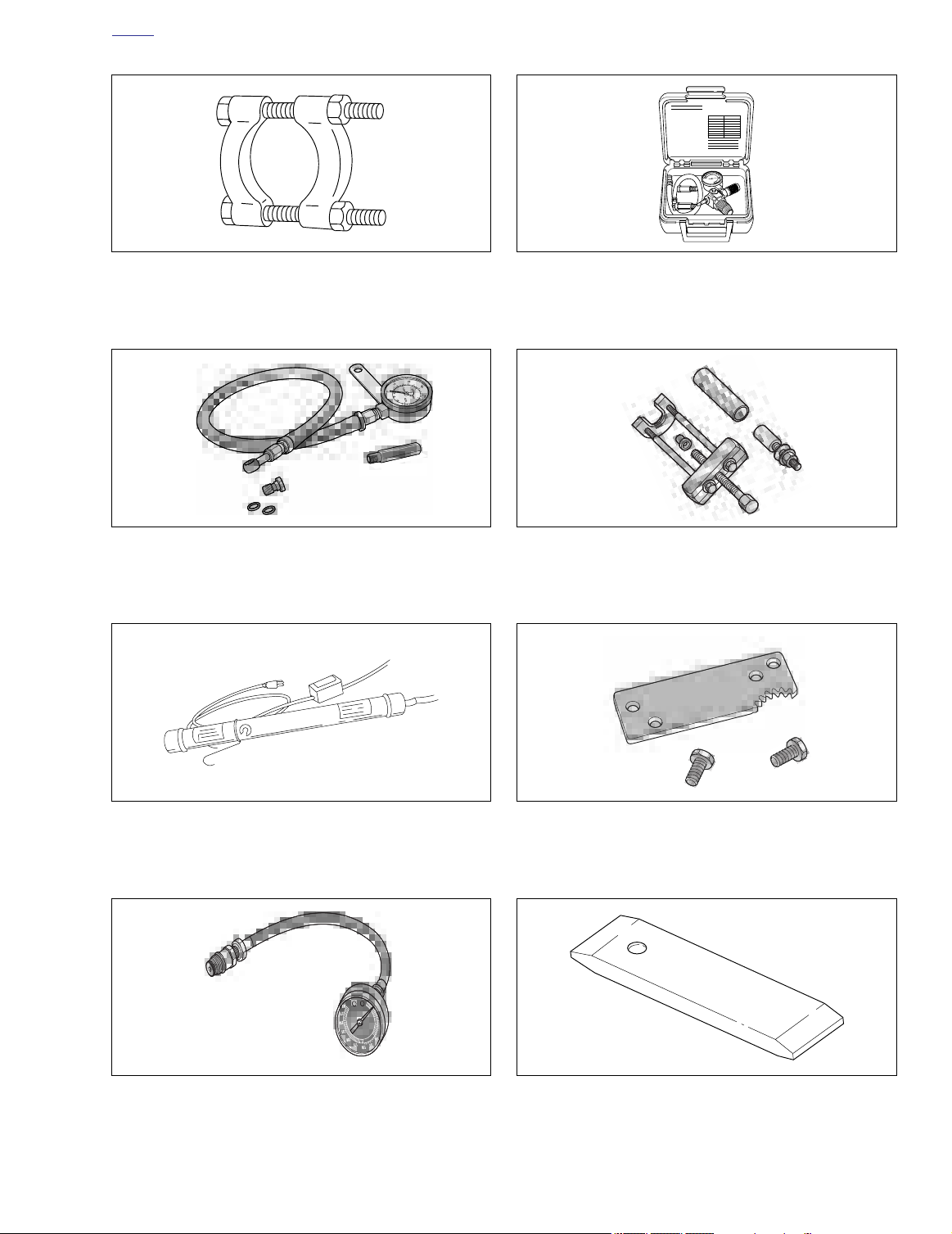
Part No. HD-95637-46A Wedge Attachment for
Claw Puller. Use with HD-95635-46.
Part No. HD-96921-52A Oil Pressure Gauge
Part No. HD-35667A Cylinder Leakdown Tester
Part No. HD-34902-B Bearing Race Remover/Installer
Part No. HD-35457 Black Light Leak Detector
Part No. HD-33223-1 Cylinder Compression Gauge
Part No. HD-43984 Crankshaft Locking Tool
Part No. HD-38362 Sprocket Locking Link (XB9S)
Part No. HD-46283 Sprocket Locking Link (XB12S)
Appendix A A-3
Page 5
HOME
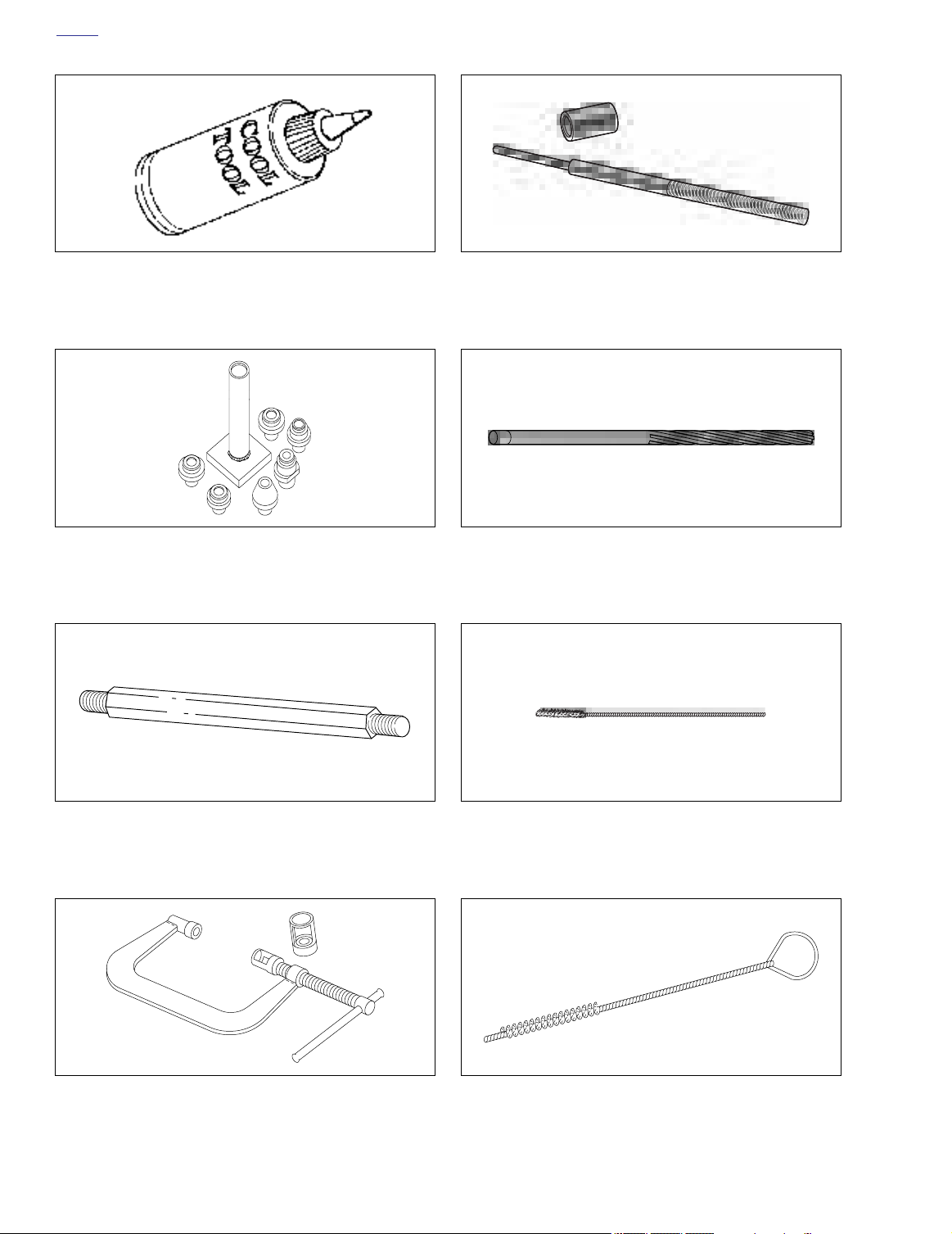
Part No. HD-39964 Reamer Lubricant (Cool Tool)
Part No. HD-39782 Cylinder Head Support
Part No. B-45524 Valve Guide Installer
Part No. B-45523 Valve Guide Reamer (7mm)
Part No. HD-39786 Cylinder Head Holding Fixture
Part No. HD-34736B Valve Spring Compressor
A-4 Appendix A
Part No. B-45525 Valve Guide Hone
Part No. HD-34751 Nylon Valve Guide Brush
Page 6
HOME
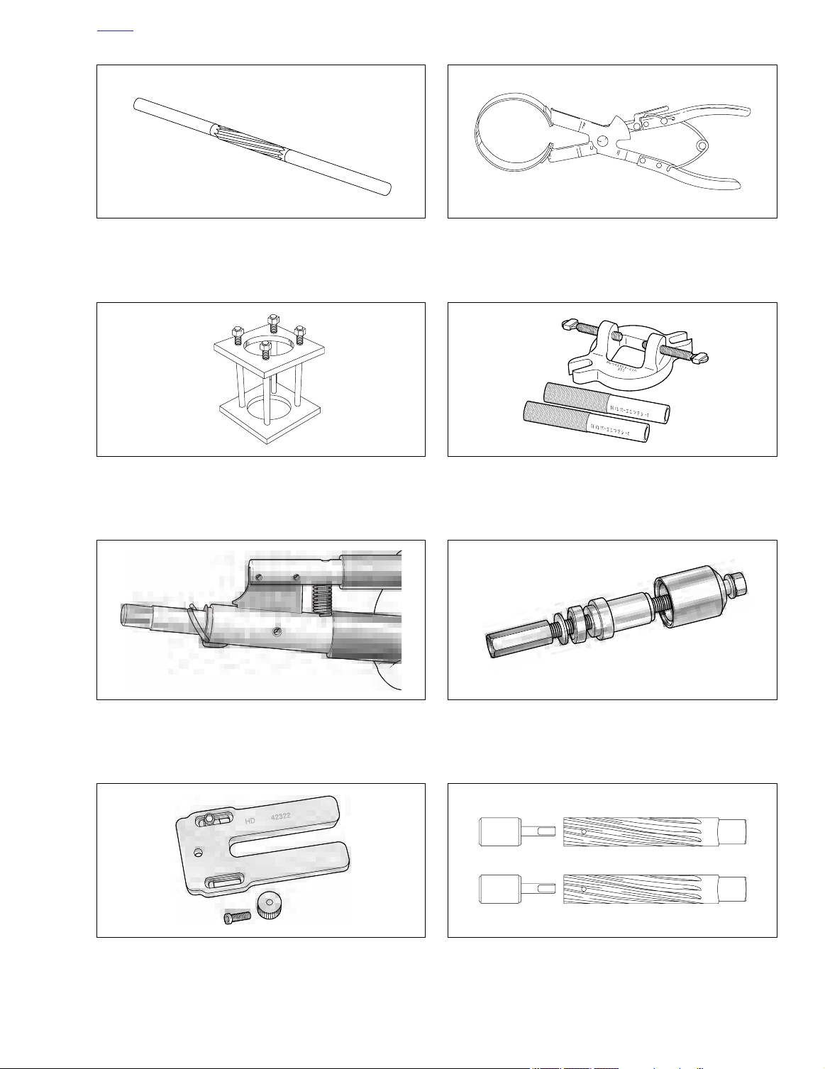
Part No. HD-94804-57 Rocker Arm Bushing Reamer
Part No. HD-33446A Cylinder Torque Plates
and Torque Plate Bolts Part No. HD-33446-86
Part No. HD-96333-51C Piston Ring Compressor
Part No. HD-95952-33B Connecting Rod
Clamping Tool
Part No. HD-34623C Piston Pin
Retaining Ring Installer/Remover
Part No. HD-42322 Piston Support Plate
Part No. HD-95970-32D Piston Pin Bushing Tool
Part No. HD-94800-26A Connecting Rod Bushing
Reamers and Pilots
Appendix A A-5
Page 7
HOME
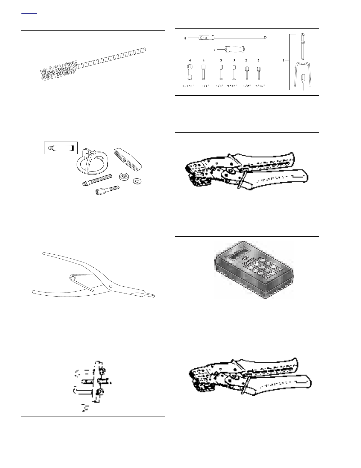
Part No. HD-35102 Wrist Pin Bushing Hone (20 mm)
Part No. HD-38515-A Clutch Spring Compressing Tool
and Part No. HD-38515-91 Forcing Screw
Part No. HD-95760-69A Bushing/Bearing Puller Tool Set.
Set includes items 1-7. Items 8 (HD-95769-69), 9 (HD-
95770-69) and 10 (HD-95771-69) are optional.
Part No. HD-39965 Deutsch Terminal Crimp Tool
Part No. J-5586 Transmission Shaft
Part No. HD-97292-61 Two Claw Puller
A-6 Appendix A
Part No. HD-41354 Speedometer Tester
Retaining Ring Pliers
Part No. HD-41609 Amp Terminal Crimp Tool
Page 8
HOME
73
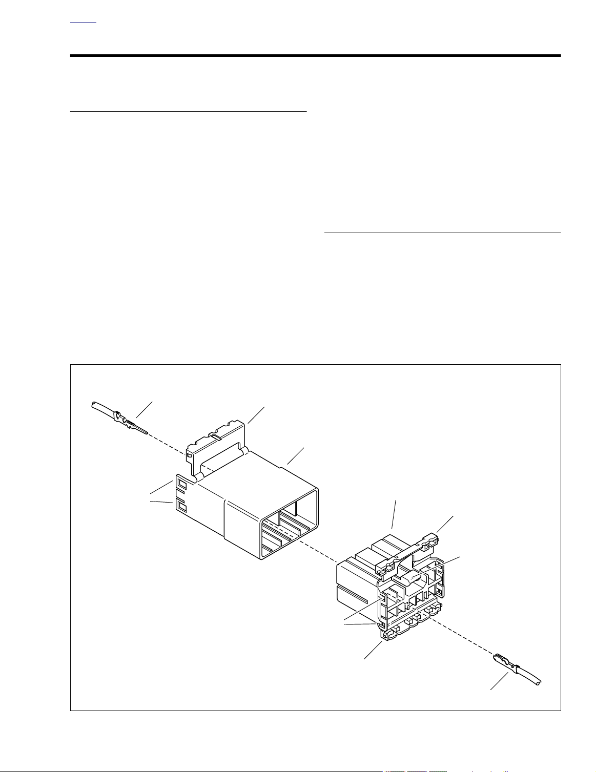
AMP MULTILOCK ELECTRICAL CONNECTORS B.1
REMOVING SOCKET/PIN
TERMINALS
1. Remove connector from the retaining de vice, either
attachment or rosebud clip.
2. Depress the b utton on the soc ket terminal side of the
connector (plug) and pull apar t the pin and soc ket
halves.
3. Bend back the latch slightly and free one side of secondary lock, then repeat the step to release the other side .
Rotate the secondar y lock outward on hinge to access
terminals in chambers of connector housing.
4. Looking in the ter minal side of the connector (opposite
the secondary lock), take note of the ca vity next to each
terminal.
5. See Figure B-1. With the flat edge against the te minal,
insert the pic k tool (Snap-On TT600-3) into the ca vity
until it stops. Pivot the end of the pick away from the terminal (locktab is inside housing) and gently tug on wire to
pull terminal from chamber. Do not tug on the wire until
the tang is released or the ter minal will be difficult t
remove. A “click” is heard if the tang is engaged but then
inadvertently released. Repeat the step without releasing
the tang.
NOTE
●
If pick tool is not available, a push pin/safety pin may be
used instead.
●
An ELECTRICAL TERMINAL CRIMP TOOL (Part No.
HD-41609) is used to install Amp Multi lock pin and
socket terminals on wires. If new terminals must be
installed, see Crimping Instructions on the next page.
INSTALLING SOCKET/PIN
TERMINALS
NOTE
For wire location purposes, numbers are stamped into the
secondary locks of both the socket and pin housings. See
Figure B-2.
1. From the secondary lock side of the connector, insert the
terminal into its respectiv e numbered chamber until it
snaps in place . For proper fit, the slot in the te minal
must face the tang in the chamber.
d0242x3x
Latch
Latch
Pin terminal
Secondary lock open
Pin housing
Socket housing
Secondary lock open
Button
Latch
Secondary lock open
Figure B-1. 10-Place Amp Multilock Connector
2004 Buell Lightning: Appendix B B-1
Socket terminal
Page 9
HOME
d0243x8x
Pin terminal
4
1
Socket terminal
4
1
Secondary lock open
Pin housing
2
Secondary lock open
Socket housing
2
3
Pick tool
Pick tool
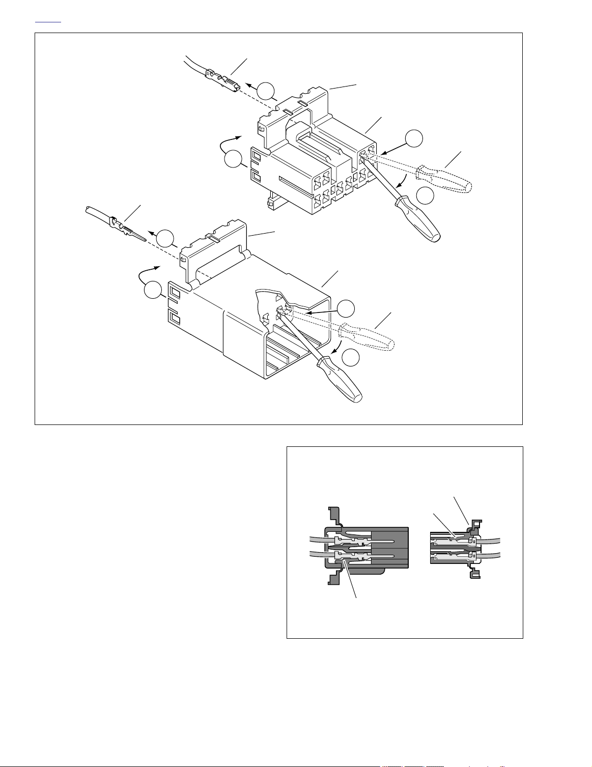
1. Open secondary lock.
2. Insert pick into cavity on inboard side
of connector.
3. Pivot end of pick to release tang.
4. Gently tug on wire to remove terminal
from housing.
Figure B-2. Release Tang and Back Out Terminals
NOTES
●
See Figure B-3. The tang in the chamber engages the
slot to lock the terminal in position.
●
On the pin side of the connector, tangs are positioned at
the bottom of each chamber, so the slot in the pin terminal (on the side opposite the crimp tails) must face downward.
●
On the socket side, tangs are at the top of each chamber ,
so the socket terminal slot (on the same side as the
crimp tails) must face upward.
Up and down can be determined by the position of the
●
release button (used to separate the pin and socket
halves). Consider the button to always be on top of the
connector.
2. Gently tug on wire end to v erify that the ter minal is
locked in place and will not back out of chamber.
3. Rotate the hinged secondar y lock inward until tabs fully
engage latches on both sides of connector.
4. Insert the soc ket housing (plug) into the pin housing
(receptacle) until it snaps in place.
5. Install connector on retaining de vice, either attachment
or rosebud clip.
3
Pin housing
Tang
d0244x8x
Figure B-3. Multilock Connector Cutaway View
Socket housing
Button
Tang
B-2 2004 Buell Lightning: Appendix B
Page 10
HOME
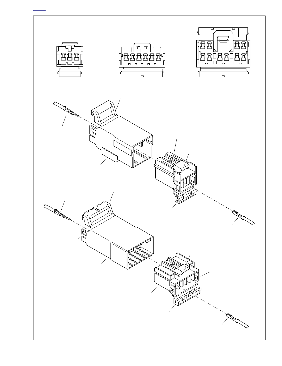
Secondary locks open (socket housings shown)
43 2 1
Stamped numbers on secondary locks indicate wire color locations
– AMP
123
– AMP
123456
3-place 6-place 12-place
Secondary lock
Pin terminal
Socket housing
Button
Pin housing
Secondary lock
Pin terminal
56 78 910
d0245x2x
Latch
Pin housing
Figure B-4. 3-Place and 6-Place Amp Multilock Connectors
Secondary lock
Socket terminal
Button
Latch
Socket housing
Secondary lock
Socket terminal
2004 Buell Lightning: Appendix B B-3
Page 11
HOME
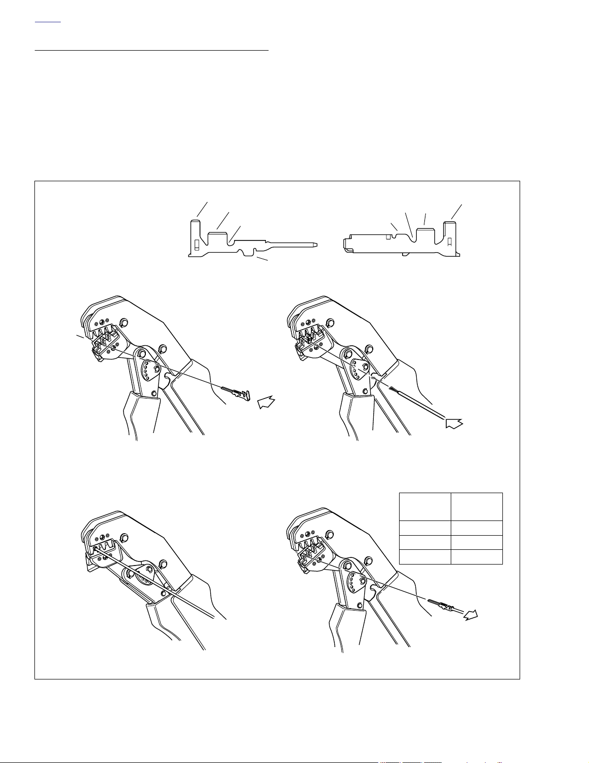
CRIMPING INSTRUCTIONS
1. Squeeze the handles to cycle the cr imp tool (Part No.
HD-41609) to the fully open position.
2. Raise locking bar by pushing up on bottom flang . With
the crimp tails facing upward, insert contact (socket/pin)
through locking bar, so that the closed side of the contact
rests on the front nest (conca ve split le vel area of the
crimp tool). See Figure B-3.
3. Release locking bar to loc k position of contact. When
correctly positioned, the loc king bar fits s ugly in the
space at the front of the core crimp tails.
1. Insulating crimp tail
2. Core crimp tail
3. Locking bar groove
4. Tang slot
1
2
3
4. Strip lead remo ving 5/32 in. (4 mm) of insulation. Insert
wires between crimp tails until ends mak e contact with
locking bar. Verify that wire is positioned so that shor t
pair of crimp tails squeeze bare wire str ands, while long
pair folds over insulation material.
5. Squeeze handle of cr imp tool until tightly closed. Tool
automatically opens when the cr imping sequence is
complete. Raise up locking bar and remove contact.
6. Inspect the quality of the core and insulation crimps. Distortion should be minimal.
3
2
1
4
4
1. Raise locking bar and seat contact
on front nest of crimp tool. Release
locking bar
d0246x8x
B-4 2004 Buell Lightning: Appendix B
3. Close and squeeze crimp tool. 4. Raise locking bar and remove contact.
Figure B-5. Amp Multilock Crimping Procedure
2. Insert stripped lead until it
contacts locking bar.
GAUGE
WIRE
CRIMP TOOL
NEST
20 Front
16 Middle
18 Rear
Page 12
HOME
4566
s0545x8x
DEUTSCH ELECTRICAL CONNECTORS B.2
GENERAL
Deutsch Connectors feature a superior seal to protect electrical contacts from dir t and moisture in harsh en vironments.
The connector also pro vides superior pin retention.
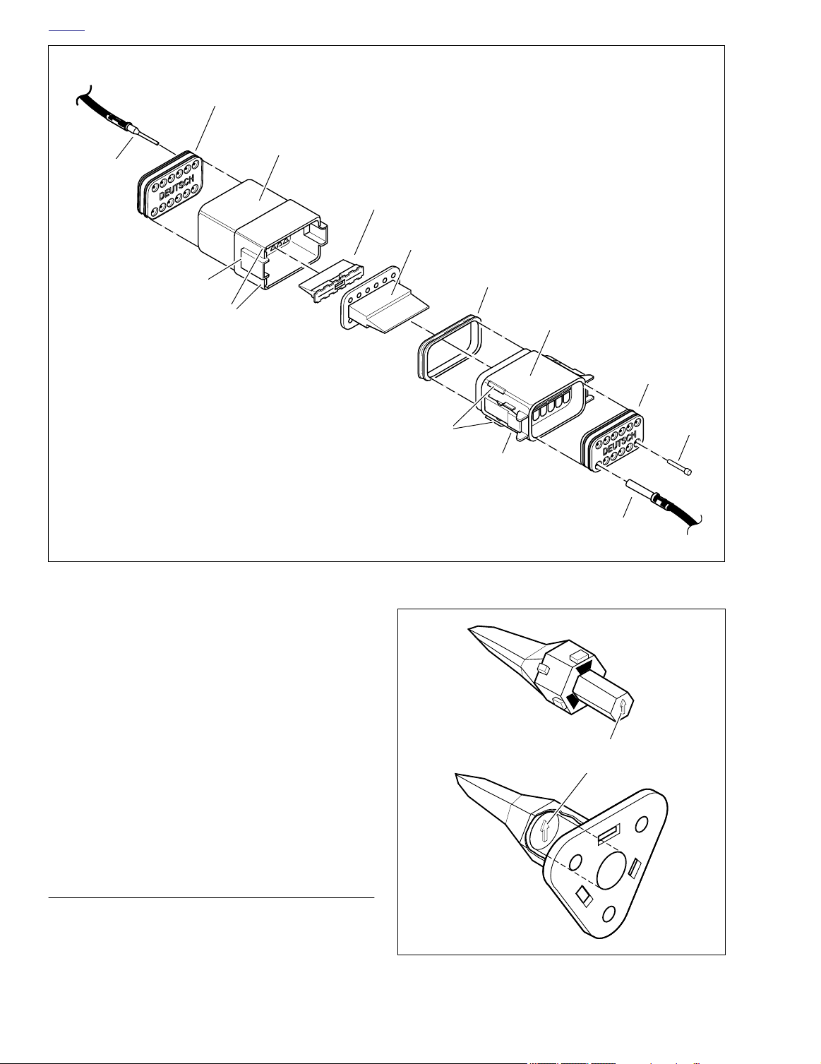
See Figure B-8. This 12-pin connector illustr ates the various
parts of the Deutsch connector . The following instructions
may be followed for all 2-pin through 12-pin Deutsch connectors.
Socket housing:
ondary locking wedge, internal seal, wire seal, seal pin.
Seal pins or plugs are installed in the wire seals of unused pin
and socket locations. If removed, seal pins must be replaced
to maintain the integrity of the environmental seal.
Pin housing:
attachment clip, secondary locking wedge, wire seal, seal pin.
alignment tabs and/or e xternal latch, sec-
NOTE
alignment grooves and/or external latch cover,
REMOVING/DISASSEMBLING
Attachment clips are attached to the pin housings of most
connectors. The clips are then attached to T-studs on the
motorcycle frame. T-studs give positive location to electr ical
connectors and wire har ness. Consistent location reduces
electrical problems and improves serviceability.
1. Push the connector to disengage small end of slot on
attachment clip from T-stud. Lift connector off T-stud.
2. Depress the e xternal latch(es) on the soc ket housing
side and use a roc king motion to separ ate the pin and
socket halves. Two-, three-, f our- and six-pin Deutsch
connectors have one e xternal latch, while eight- and
twelve-pin connectors have two, both of which m ust be
pressed simultaneously to separ ate the connector
halves.
Figure B-6. Remove Secondary Locking Wedge
NOTE
With few exceptions, the socket housing can always be found
on the accessory side, while the pin side of the connector is
connected to the wiring harness.
REMOVING/INSTALLING SOCKETS
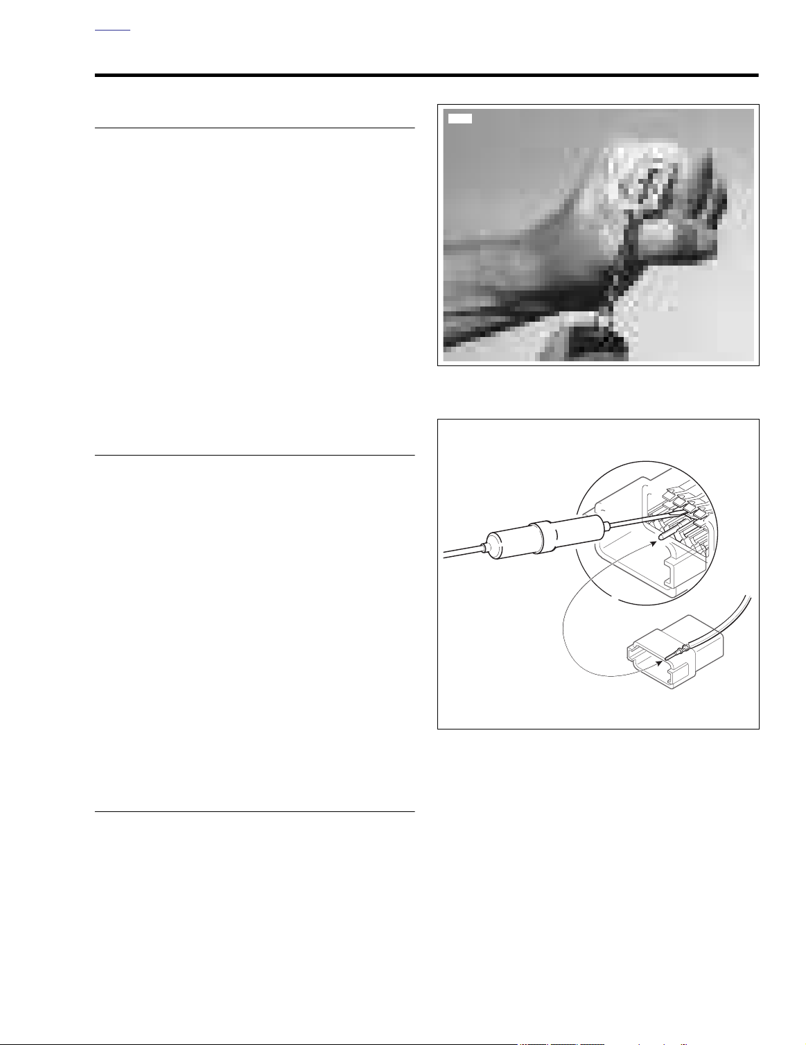
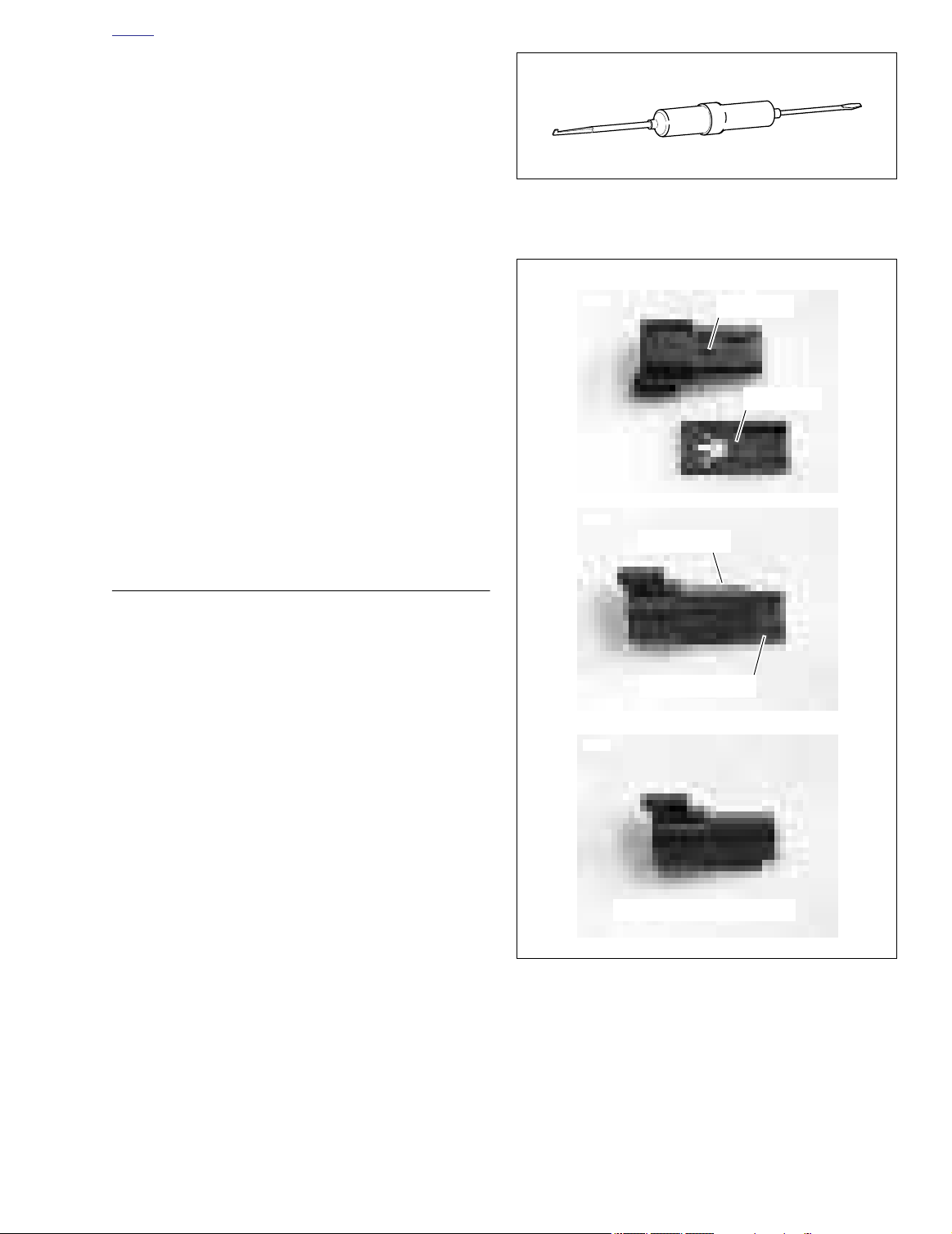
1. See Figure B-7. Remove the secondar y locking wedge.
Insert the b lade of a small scre wdriver between the
socket housing and locking wedge inline with the g roove
(inline with the pin holes if the groove is absent). Turn the
screwdriver 90 degrees to pop the wedge up.
2. See Figure B-8. Gently depress terminal latches inside
socket housing and bac k out soc kets through holes in
rear wire seal.
Figure B-7. Depress Terminal Latches/Back Out Pins
NOTE
An ELECTRICAL TERMINAL CRIMP TOOL (Part No. HD-
39965) is used to install Deutsch pin and socket terminals on
wires. If
tions included with the crimping tool or see Crimping Instructions in this section.
Fit rear wire seal into bac k of soc ket housing, if remo ved.
Grasp socket approximately 1.0 in. (25.4 mm) behind the
contact barrel. Gently push sockets through holes in wire seal
into their respectiv e chambers. Feed socket into chamber
until it “clicks” in place. Verify that socket will not bac k out of
chamber; a slight tug on the wire will confi m that it is properly
locked in place.
new
terminals must be installed, follow the instruc-
2004 Buell Lightning: Appendix B B-5
Page 13
HOME
d0248x8x
terminal
Wire seal
Pin housing
Pin
Locking wedge
Locking wedge
Latch cover
Alignment grooves
Alignment tabs
Figure B-8. 12-pin Deutsch Connector (Exploded View)
3. Install internal seal on lip of soc ket housing, if removed.
Insert tapered end of secondar y locking wedge into
socket housing and press do wn until it snaps in place .
The wedge fits into the center roove within the soc ket
housing and holds the terminal latches tightly closed.
NOTES
●
While rectangular wedges do not require a special orientation, the conical secondary locking wedge of the 3-pin
connector must be installed with the arrow pointing
toward the external latch. See Figure B-9.
●
If the secondary locking wedge does not slide into the
installed position easily, verify that all terminals are fully
installed in the socket housing. The lock indicates when
terminals are not properly installed by not entering its
fully installed position.
Internal seal
Socket housing
Wire seal
Seal pin
External latch
Socket terminal
d0249x3x
Pin
housing
Arrow points to
external latch
REMOVING/INSTALLING PINS
1. Remove the secondar y locking wedge. Use the hook ed
end of a stiff piece of mechanics wire a needle nose pliers, or a suitable pick tool (Part No. HD-41475-100). See
Figure B-10.
2. Gently depress ter minal latches inside pin housing and
back out pins through holes in wire seal.
B-6 2004 Buell Lightning: Appendix B
Socket
housing
Figure B-9. Depress Terminal Latches/Back Out Pins
Page 14
HOME
5893
5892
5891
Lock tab
Lock bar
Pin housing
Attachment clip
Attachment clip installed
NOTE
An ELECTRICAL TERMINAL CRIMP TOOL (Part No. HD-
39965) is used to install Deutsch pin and socket terminals on
wires. If
new
terminals must be installed, see Crimping
Instructions in this section.
3. Fit wire seal into bac k of pin housing. Grasp crimped pin
approximately 1.0 in. (25.4 mm) behind the contact barrel. Gently push pins through holes in wire seal into their
respective numbered locations. Feed pin into chamber
until it “clicks” in place. Verify that pin will not bac k out of
chamber; a slight tug on the wire will confi m that it is
properly locked in place.
4. Insert tapered end of secondar y locking wedge into pin
housing and press do wn until it snaps in place . The
wedge fits in the center roove within the pin housing
and holds the terminal latches tightly closed.
NOTES
●
While rectangular wedges do not require a special orientation, the conical secondary locking wedge of the 3-pin
connector must be installed with the arrow pointing
toward the external latch. See Figure B-9.
●
If the secondary locking wedge does not slide into the
installed position easily, verify that all terminals are fully
installed in the pin housing. The lock indicates when terminals are not properly installed by not entering its fully
installed position.
Figure B-10. Deutsch Connector Pick Tool
(Part No. HD-41475-100)
ASSEMBLING/INSTALLING
1. Insert socket housing into pin housing until it snaps in
place. Two-, three-, four- and six-pin Deutsch connectors
have one external latch on the socket half of the connector. To fit the hal es of the connector together , the latch
on the soc ket side must be aligned with the latch co ver
on the pin side.
For those connectors with tw o external latches (8-pin
and 12-pin), a diff erent system is used to pre vent
improper assembly. Align the tabs on the socket housing
with the grooves on the pin housing. Push the connector
halves together until the latches “click.” If latches do not
click (latch), press on one side of the connector until that
latch engages, then press on the opposite side to
engage the other latch.
Deutsch connectors are color coded for location purposes.
Those connectors associated with
as the front and rear
nectors, including those associated with right side accessories, are black.
If it should become necessary to replace a plug or receptacle,
please note that the 8-pin and 12-pin gray and black connectors are not interchangeable. Since location of the alignment
tabs differ between the black and gray connectors, plugs or
receptacles must be replaced by those of the same color. If
replacing both the socket and pin halves, then the black may
be substituted for the gra y, and vice versa. The socket and pin
halves of all other connectors are interchangeable, that is, the
black may be mated with the gray, since the alignment tabs
are absent and the orientation of the external latch is the
same.
NOTE
left
turn signals, are
left
side accessories, such
gray
. All other con-
Figure B-11. Attachment Clip Installation
2. See Figure B-11. Fit the attachment clip to the pin housing, if remo ved. Place large end of slot on attachment
clip over T-stud on fr ame. Push assemb ly forward to
engage small end of slot.
2004 Buell Lightning: Appendix B B-7
Page 15
HOME
d0250x8x
Locking bar
1. Insert contact through middle
hole in locking bar.
3. Close and squeeze crimp tool 4. Raise locking bar and remove
Insulation crimp Core crimp
Figure B-12. Deutsch Crimping Procedure
2. Insert stripped lead until it
contacts locking bar.
contact.
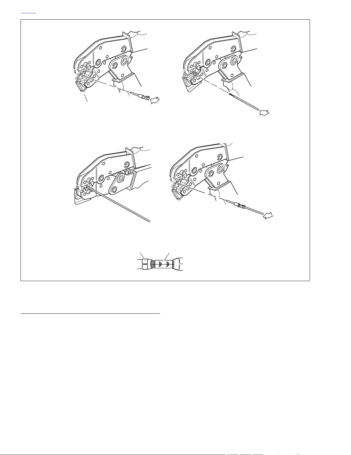
CRIMPING INSTRUCTIONS
1. See Figure B-12. Squeeze the handles to cycle the crimp
tool to the fully open position.
2. Raise locking bar by pushing up on bottom flang . With
the crimp tails facing upward and the rounded side of the
contact barrel resting on the conca ve split level area of
the crimp tool, insert contact (socket/pin) through middle
hole of locking bar.
3. Release locking bar to loc k position of contact. If the
crimp tails are slightly out of vertical alignment, the crimp
tool automatically rotates the contact so that the tails
face straight upward. When correctly positioned, the
locking bar fits s ugly in the space betw een the contact
band and the core crimp tails.
B-8 2004 Buell Lightning: Appendix B
4. Strip lead remo ving 5/32 in. (4 mm) of insulation. Insert
wires between crimp tails until ends mak e contact with
locking bar. Verify that wire is positioned so that shor t
pair of crimp tails squeeze bare wire str ands, while long
pair folds over insulation material.
5. Squeeze handle of cr imp tool until tightly closed. Tool
automatically opens when the cr imping sequence is
complete. Raise up locking bar and remove contact.
6. Inspect the quality of the core and insulation crimps. Distortion should be minimal.
Page 16
HOME
d0251x3x
11
11
10
10
9
8
7
6
2-pin connector
5
4
2
1
3
9
8
7
11
10
SOCKET SIDE PIN SIDE
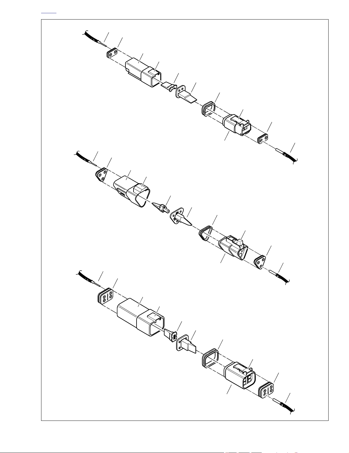
1. Socket terminal
2. Wire seal
3. Socket housing
4. External latch
5. Internal seal
6. Locking wedge
7. Locking wedge
8. Latch cover
9. Pin housing
10. Wire seal
11. Pin terminal
6
5
3-pin connector
4
2
1
3
9
8
7
6
5
4-pin connector
4
2
1
3
Figure B-13. 2-Pin, 3-pin and 4-pin Deutsch Connectors
2004 Buell Lightning: Appendix B B-9
Page 17
HOME
PACKARD ELECTRICAL CONNECTORS B.3
GENERAL
From a ser vicing standpoint, there are tw o basic types of
Packard electrical connectors, those with pull-to-seat ter minals and those with push-to-seat terminals.
Look into the mating end of the connector . If it appears that
the terminal can be extracted from this side , then it is probably the pull-to-seat type.
At least one Packard pull-to-seat terminal can be easily recognized by the presence of a locking ear. The ear engages a
slot in the connector housing and pre vents the terminal from
being removed from the wire end side of the connector . The
ear also acts as a str ain relief in the e vent that the wires are
pulled and fur ther inhibits mo vement of the ter minal inside
the chamber. For an example of this type of connector , note
the MAP sensor connector [80].
d0258x8x
A
Unlike most connectors , where the ter minals are pulled out
the wire end of the connector , to remove the terminals from
the pull-to-seat connectors , the ter minal is pushed out the
mating end of the connector. Once a
onto the end of the wire , the wire is pulled to dr aw the terminal back inside the chamber of the connector housing.
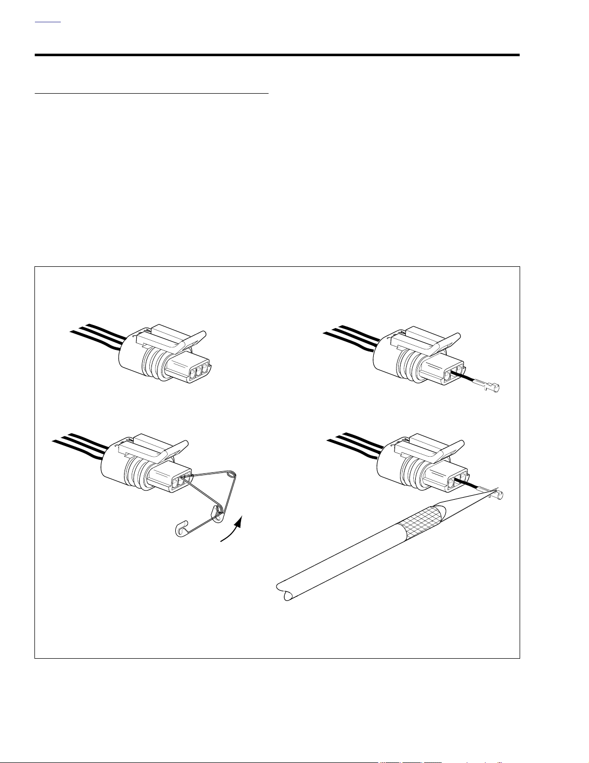
Tw o types of P ackard pull-to-seat electr ical connectors are
used. One type has an e xternal latch to loc k the pin and
socket halves together, while the other mak es use of a wireform. See Figure B-14. The manner in which the ter minals
are picked differs between these two types of connectors, as
further described below.
new
terminal is crimped
C
Locate tang on latch side of chamber.
B
Pivot end of pin to depress tang.
Push on wire end of lead to
remove terminal.
D
Raise tang and re-install terminal.
Figure B-14. Packard Connectors
B-10 2004 Buell Lightning: Appendix B
Page 18

HOME
PULL-TO-SEAT TERMINALS
Removing External Latch Type
To remove a pull-to-seat terminal from connectors with external latches, proceed as follows:
1. Remove the connector from the retaining de vice, if
present.
2. Bend back the e xternal latch(es) slightly and separ ate
the pin and socket halves of the connector.
3. To free a pull-to-seat ter minal from the connector housing, first look into the mating end of the connector to fi
the locking tang. See A in Figure B-14. The tangs are
always positioned in the middle of the chamber and are
on the same side as the external latch. On those connectors with loc king ears, the tang is on the side opposite
the ear.
4. At a slight angle , gently inser t the point of a one inch
safety pin do wn the middle of the chamber (about 1/8
inch) and piv ot the end of the pin to ward the ter minal
body. When a click is heard, remo ve the pin and repeat
the procedure. See B in Figure B-14. The click is the
sound of the tang retur ning to the loc ked position as it
slips from the point of the pin. Pick at the tang in this
manner until the clicking stops and the pin seems to slide
in at a slightly greater depth than it had previously. This is
an indication that the tang has been depressed.
NOTES
●
On those terminals that have been extracted on a previous occasion, no clicking sound may be heard when the
pin is pivoted to depress the tang, but proceed as if the
clicking is audible and then push on the wire end of the
lead to check if the terminal is free.
When picking multiple terminals, the end of the pin may
●
become malleable. For best results, continue the procedure with a new safety pin.
5. Remove the pin and push on the wire end of the lead to
extract the ter minal from the mating end of the connector. See C in Figure B-14. If necessary, pull back the conduit and remo ve the wire seal at the bac k of the
connector to introduce some slack in the wires.
NOTE
A series of Packard Electrical Terminal Crimp Tools are available to install Packard pin and socket terminals on wires. If
new
terminals must be installed, see Crimping Instructions.
Installing External Latch Type
NOTE
For wire location purposes, alpha characters are stamped
into the socket housings.
1. To install a terminal back into the chamber of the connec-
tor housing, use a thin flat lade, like that on an X-Acto
knife, and carefully bend the tang outward away from the
terminal body. See D in Figure B-14.
2. Gently pull on the lead at the wire end of the connector to
draw the terminal back into the chamber. A click is heard
when the terminal is properly seated.
3. Push on the lead to v erify that the ter minal is locked in
place.
4. Push the pin and socket halves of the connector together
until the latches “click.”
2004 Buell Lightning: Appendix B B-11
Page 19

HOME
PUSH-TO-SEAT TERMINALS
The Packard push-to-seat terminal connectors found on Softail model vehicles are listed below.
●
Ignition Switch [33]
●
Fuse Terminals
MAP Sensor [80]
●
Removing Push-to-Seat Terminals
Like most connectors , Packard push-to-seat ter minals are
pulled out the wire end of the connector . To remove a pushto-seat terminal, proceed as follows:
1. Remove the connector from the retaining de vice, if
present.
2. Bend back the e xternal latch(es) slightly and separ ate
the pin and socket halves of the connector.
NOTE
Both the Ignition Light/Key Switch and the Main Power connectors are provided with secondary locks. The secondary
lock, which may be molded onto the connector or exist as a
separate piece, aids in terminal retention. Secondary locks
must be opened (or removed) before the ter minals can be
extracted from the connector housing.
3. Open or remove the secondary lock. Bend back the latch
slightly and free one side of the secondar y lock, then
repeat the step to release the other side. Rotate the secondary lock outward on hinge to access the ter minals in
the chambers of the connector housing.
4. Looking in the mating end or terminal side of the connec-
tor (opposite the secondary lock), take note of the larger
cavity next to each terminal.
5. Insert the pick (Snap-On TT600-3) into the cavity until it
stops. Pivot the end of the pic k toward the ter minal to
depress the loc king tang. Remove the pic k and gently
tug on the wire to pull the ter minal from the wire end of
the connector. Repeat the step if the ter minal is still
locked in place.
NOTE
A series of Packard Electrical Terminal Crimp Tools are available to install Packard pin and socket terminals on wires. If
new terminals must be installed, see Crimping Instructions.
Installing Push-to-Seat Terminals
NOTE
For wire location purposes, alpha characters are stamped
onto the secondary locks or onto the wire end of the connector housing.
1. To install a terminal back into the chamber of the connec-
tor housing, use a thin flat lade, like that on an X-Acto
knife, and carefully bend the tang outward away from the
terminal body.
2. Push the lead into the chamber at the wire end of the
connector. A click is heard when the ter minal is properly
seated.
3. Gently tug on the wire end to v erify that the ter minal is
locked in place and will not back out of the chamber.
4. Close or install the secondar y lock. Rotate the hinged
secondary lock inward until tabs fully engage latches on
both sides of connector.
5. Push the pin and socket halves of the connector together
until the latches “click.”
6. Install connector on retaining device, if present.
B-12 2004 Buell Lightning: Appendix B
Page 20
HOME
Tool tip
Packard 115 Packard 271
d0259x8x
d0260x8x
1. Insulation
2. Insulation crimp
3. Core crimp
1 2
3
CRIMPING INSTRUCTIONS
1. Strip wire lead removing 5/32 in. (4 mm) of insulation.
2. Compress handles until ratchet automatically opens.
NOTE
Always perform core crimp before insulation/seal crimp.
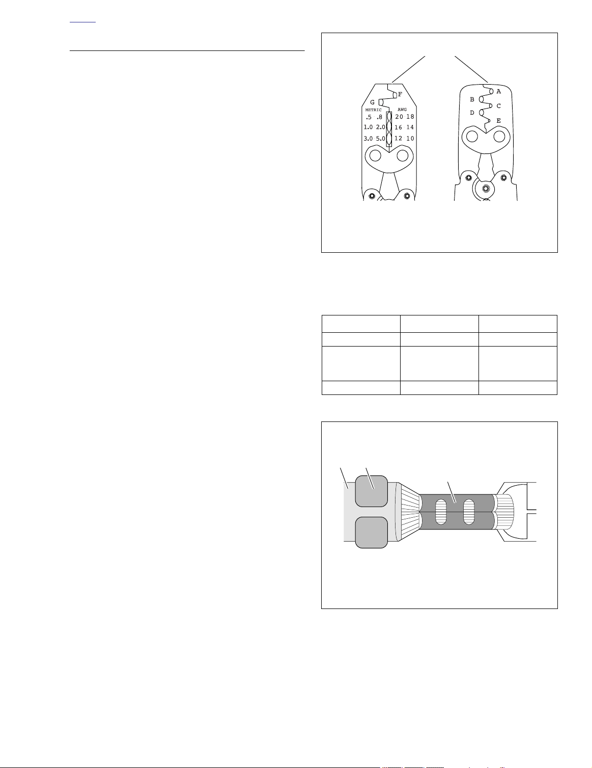
3. See Ta b le B-1. Determine the correct dye or nest for the
core crimp.
NOTE
When the word “TIP” appears in the Cr imp Table, use the tip
of the tool specified to perform the core crimp procedure. See
Figure B-15.
4. Lay the back of the core cr imp tails on the appropr iate
nest. Be sure the core cr imp tails are pointing to wards
the forming jaws.
5. Gently apply pressure to handles of tool until cr impers
slightly secure the core crimp tails.
6. Insert stripped wire between crimp tails. Verify that wire
is positioned so that shor t pair of cr imp tails squeez e
bare wire strands, while long pair folds over insulation or
seal material.
7. Squeeze handle of cr imp tool until tightly closed. Tool
automatically opens when the cr imping sequence is
complete.
8. Ta ble B-1. Determine the correct dye or nest for the insulation/seal crimp.
Figure B-15. Packard Terminal Crimp Tools
Table B-1. Packard Terminal Crimp Tools
SPECIFICATION PACKARD 115 PACKARD 271
Part No. HD-38125-8 HD-38125-7
Non-sealed
Ty p e of Crimp
Dye/nests F-G A-E
terminals,
butt splices
Non-sealed
terminals
9. Lay the bac k of the insulation/seal cr imp tails on the
appropriate nest. Be sure the insulation/seal cr imp tails
are pointing towards the forming jaws.
10. Squeeze handle of cr imp tool until tightly closed. Tool
automatically opens when the cr imping sequence is
complete.
11. See Figure B-16. Inspect the quality of the core (3) and
insulation/seal (2) crimps. Distortion should be minimal.
Figure B-16. Inspect Core and Insulation/Seal Crimps
2004 Buell Lightning: Appendix B B-13
Page 21
HOME
ELECTRICAL CONNECTORS B.4
GENERAL
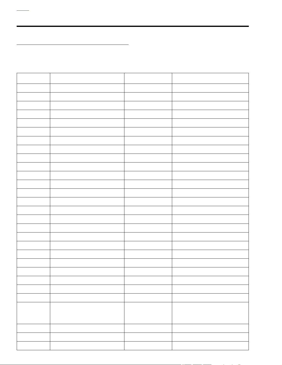
The following table provides a brief description of the connectors found on the Buell Lightning.
Connector numbers are listed in [brackets] in this manual.
Table B-2. Electrical Connector and Location Table
CONNECTOR COMPONENT(S) DESCRIPTION LOCATION
[10] ECM (black) 12-place Deutsch under seat
[11] ECM (gray) 12-place Deutsch under seat
[14] cam position sensor 3-place Deutsch under sprocket cover
[18] right rear turn signal 2 1-place bullet under seat
[19] left rear turn signal 2 1-place bullet under seat
[22] right hand controls 4-place Multilock behind windscreen
[24] left hand controls 4-place Multilock behind windscreen
[30] flashe 5-place Amp behind windscreen
[31] right front turn signal 2 1-place bullet behind windscreen
[31] left front turn signal 2 1-place bullet behind windscreen
[33] ignition switch 4-place Augat behind windscreen
[38] headlamp connector 4-place Amp behind windscreen
[39] instrument module 20-place Multilock in front modules behind windscreen
[45] license plate lamp 2 1-place bullet under seat
[46] stator 4-place Deutsch under sprocket cover
[65] vehicle speed sensor 3-place Deutsch under sprocket cover
[77] voltage regulator 2-place Packard under sprocket cover
[83] ignition coil 3-place Packard beneath airbox base
[84] front fuel injector 2-place Packard beneath airbox base
[85] rear fuel injector 2-place Packard beneath airbox base
[86] fuel pump 4-place Multilock left side of rear shock absorber
[88] throttle position sensor 3-place Packard right side of engine between cylinders
[89] intake air temperature sensor 2-place Amp in airbox base
[90] engine temperature sensor 1-place bullet beneath airbox base
[91A] data link 4-place Deutsch under seat, right side of vehicle
2-place spade
[93] tail light
1-place spade
(ground)
back of tail light, under seat
[95] clutch switch 2-place Multilock underside of clutch lever assembly
[97] cooling fan 2-place Multilock behind rear cylinder, under seat
[120] oil pressure switch post terminal crankcase above oil filte
B-14 2004 Buell Lightning: Appendix B
Page 22

HOME
Table B-2. Electrical Connector and Location Table
CONNECTOR COMPONENT(S) DESCRIPTION LOCATION
[121] front brake switch 2-place Multilock
[121] rear brake switch 2-place Multilock under seat
[122] horn spade terminals behind windscreen
[128] starter solenoid spade terminals top of starter
[131] neutral switch 1-place bullet under sprocket cover
[134] bank angle sensor 6-place Sumitomo under seat
[137] oxygen sensor 1-place Packard behind rear cylinder head
underside of front master cylinder
assembly
2004 Buell Lightning: Appendix B B-15
Page 23
HOME
INDEX TO WIRING DIAGRAMS B.5
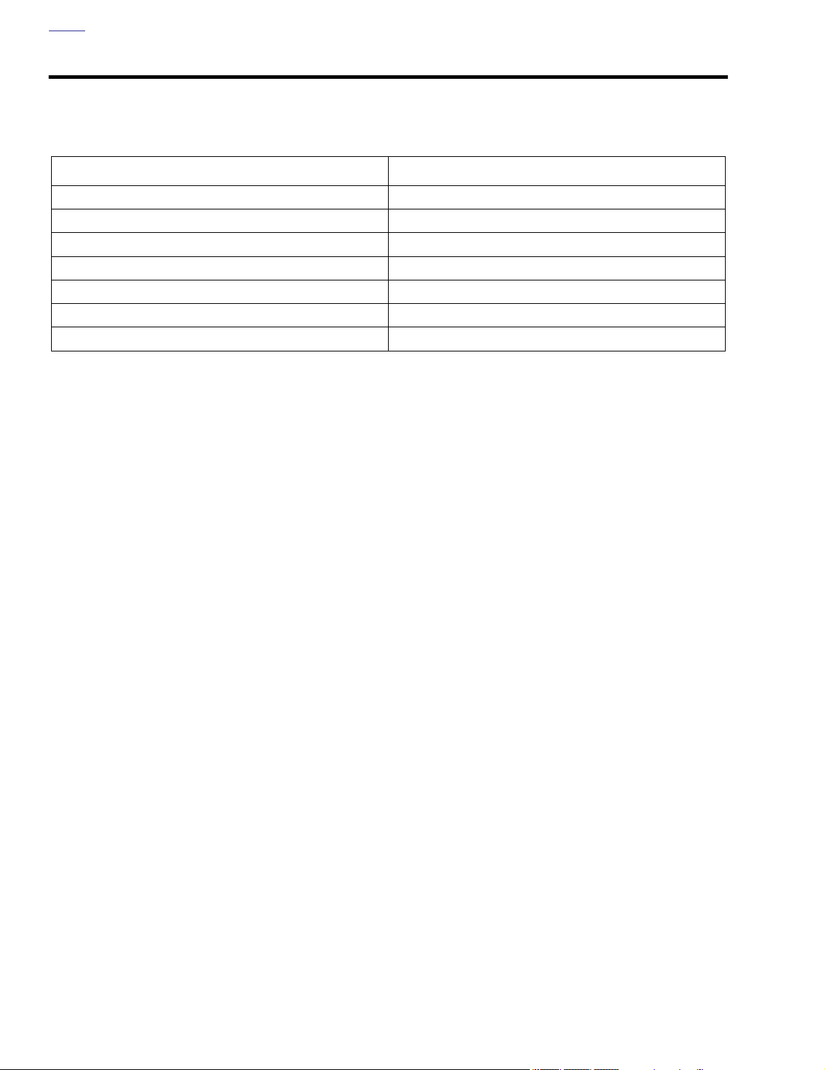
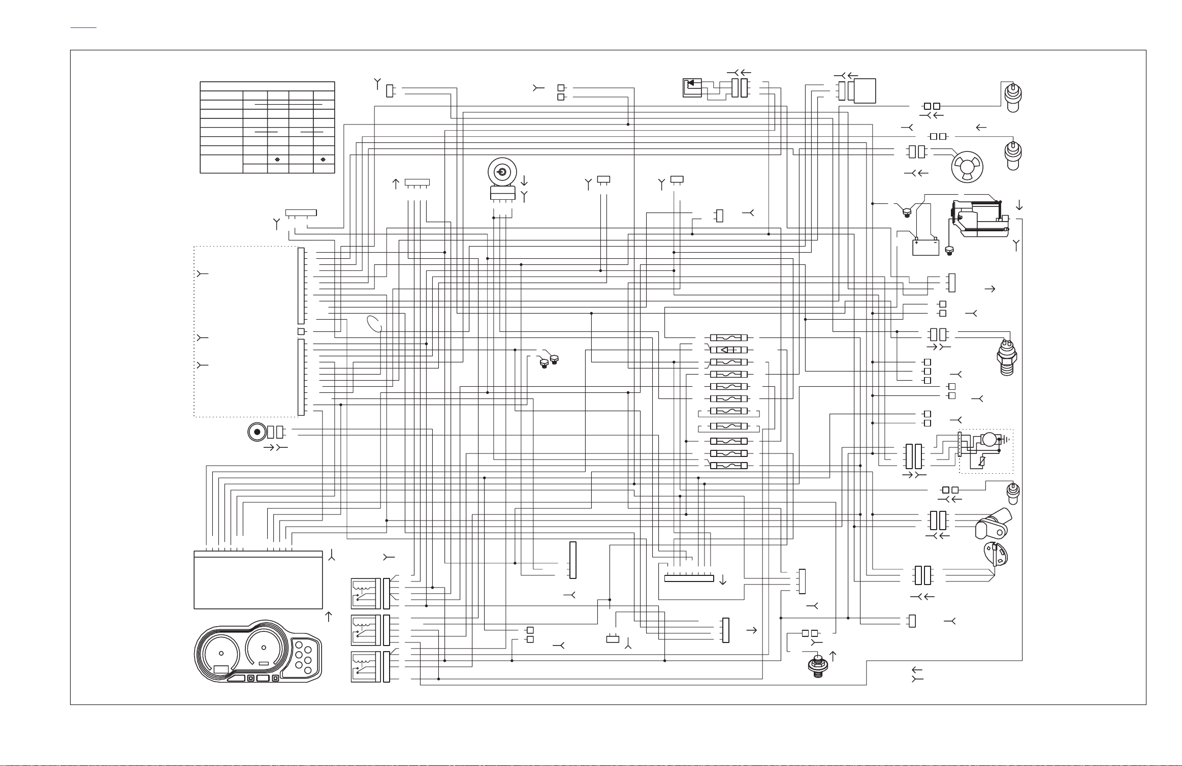
Table B-3. Wiring Diagrams
DIAGRAM PAGE
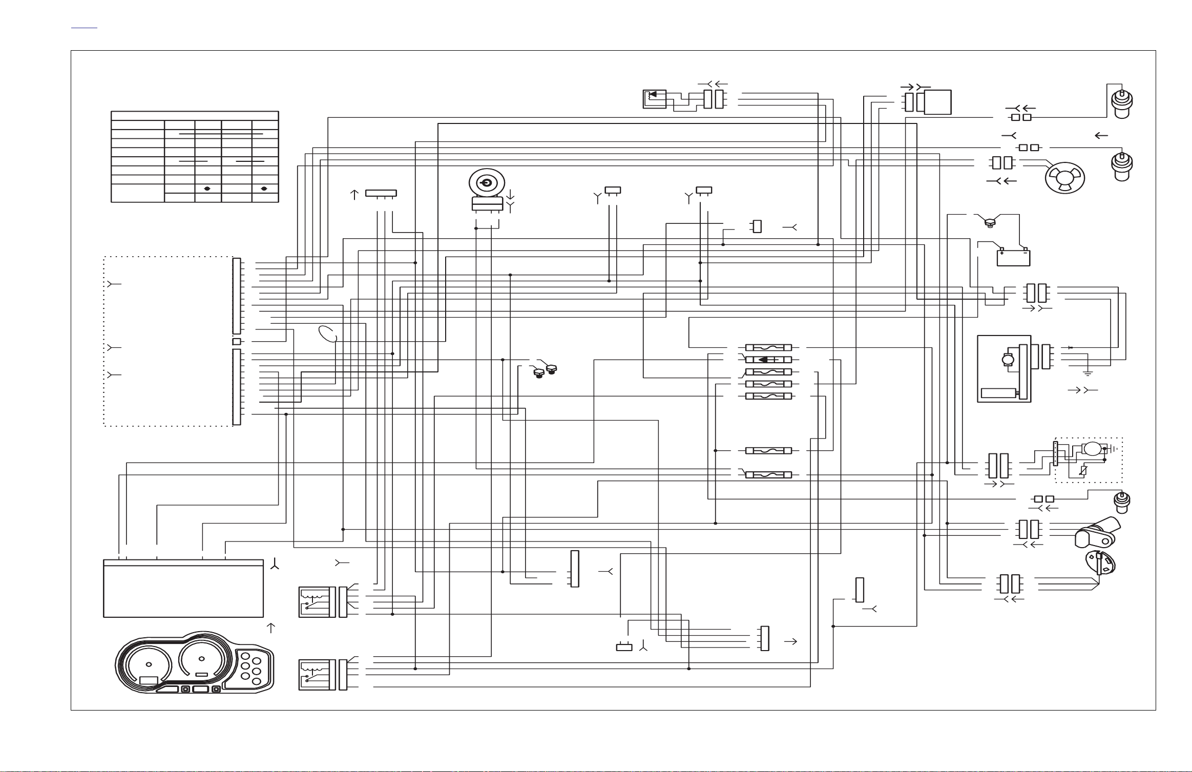
Main harness B-17
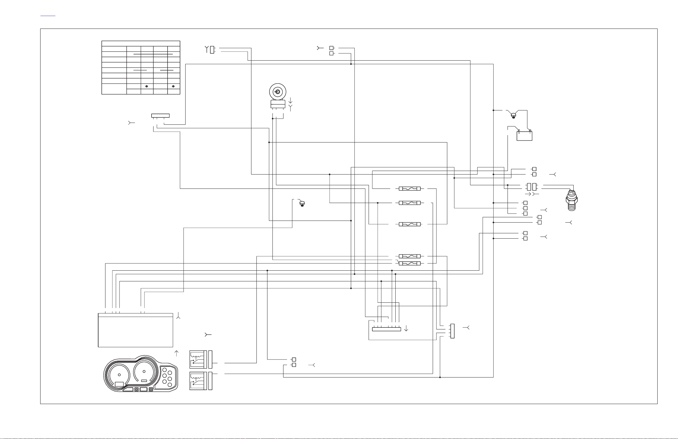
Engine management circuit B-18
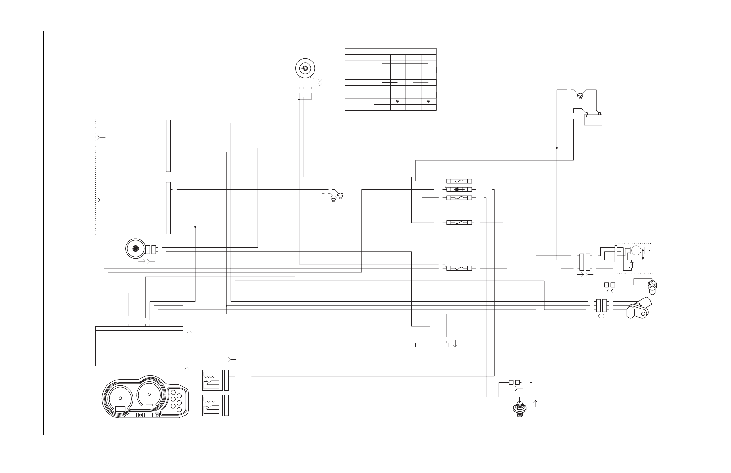
Lighting circuit B-19
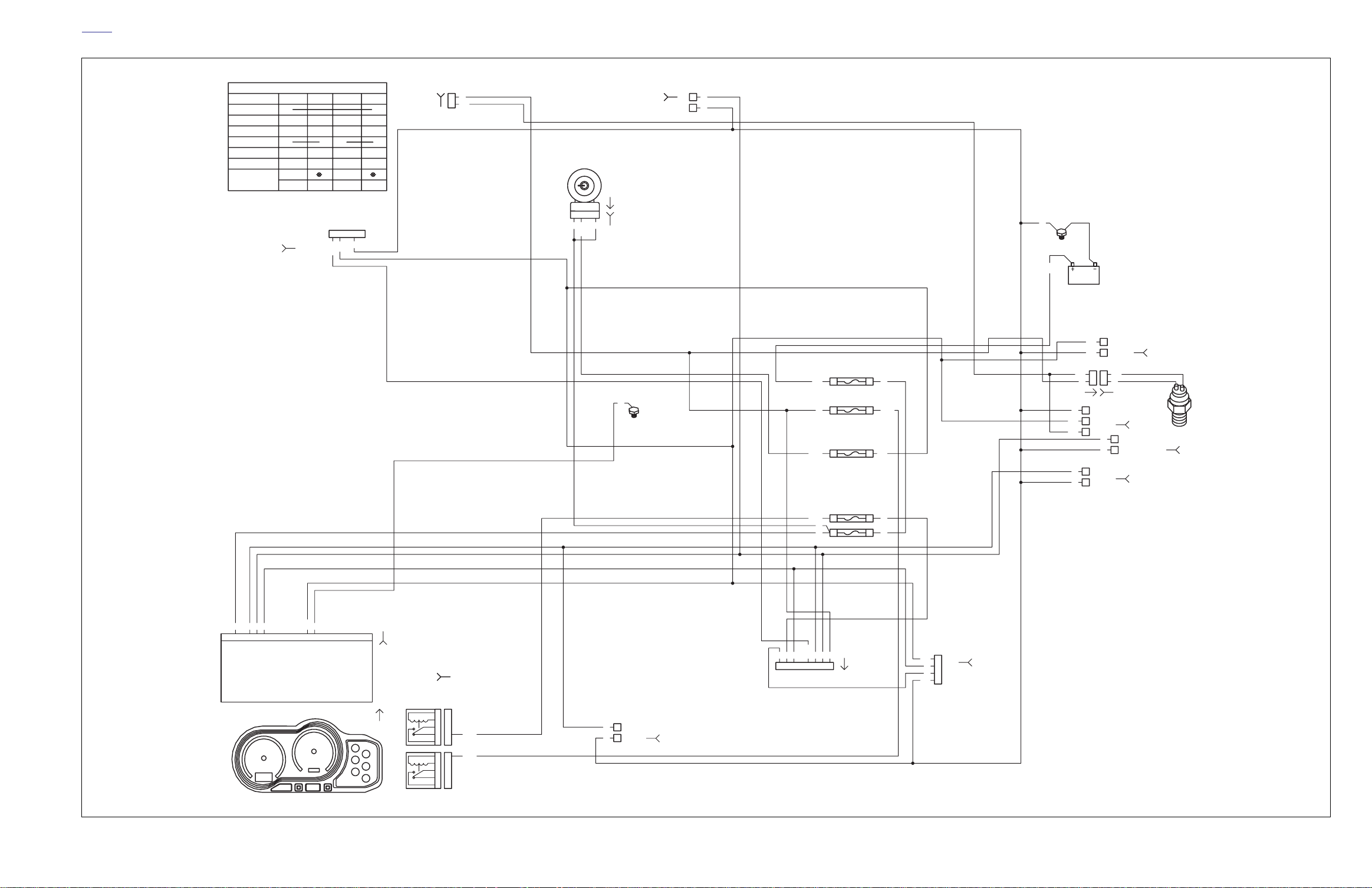
Horn and instruments circuit B-20
Starting circuit B-21
Charging circuits B-22
Component Circuits B-23
B-16 2004 Buell Lightning: Appendix B
Page 24
HOME
bs0016xx
2
GY
GN/GY
Y/BK
WYBE
LT.GN/Y
R/Y
TN/Y
TN/Y
GY/O
R/GY
R/BK
V/BN
LT.GN/R
[88B] [88A]
BK/W
O
O
R
BK
BK
R
R
R
BK/W
11
2
2
V/Y
3
3
R/W
IAT
1
2
[89B]
[91A]
35
34
23
24
21
22
25 BK
26
36
37
38
[61B]
R
TN/LT.GN
R/BK
Y/BN
R/BK
O/W
BK
Y
BE
R
BATTERY
41
DIODE
40
BRAKE/HORN/MUFFLER
29
COOLING FAN
30
IGNITION
27
ACCESSORY
28
SPARE
31
SPARE
32
ECM
42
LIGHTS
43
KEY SWITCH
44
OBNV
[24A]
DATA LINK
1
2
BK
3
V/R
4
GY
IGNITION SWITCH WIRING DIAGRAM
KEY POSITION
PARK
LOCK
OFF
ON
WIRE COLOR
WIRE SECT mm
CONNECTING
ECM
5V SENSOR POWER
THROTTLE POS SENSOR
(GY)
CAMSHAFT POS SENSOR
[11B]
VEHICLE SPEED SENSOR
ENGINE TEMP INPUT
SERIAL DATA RECEIVE
SERIAL DATA TRANSMIT
ACTIVE MUFFLER CONTROL
[164B]
(BK)
[10B]
SWITCHED IGNITION
SYSTEM GROUND A
FUEL PUMP OUTPUT
CHECK ENGINE LAMP
INJECTOR FRONT OUTPUT
FRONT COIL PRIMARY
REAR COIL PRIMARY
INJECTOR REAR OUTPUT
ACTIVE MUFFLER FEEDBACK
BANK ANGLE SENSOR
SYSTEM GROUND B
TACHOMETER OUTPUT
HORN
R
2
1
1
23456789
3
7
BATTERY
TN/Y
4
5
6
NEUTRAL
LEFT TURN
RIGHT TURN
GN/Y
BK/Y
WBNV
8
7
HIGH BEAM
OIL PRESSURE
CHECK ENGINE
CA
0
00
R/BK
R
1
1
+
BATTERY
USER + USER +
BATTERY
[30B]
KEEP ALIVE
11
22
12 2019181716151413
11
GROUND
IGNITION
12345
V/BN
BK
Y/BK
[122B]
Y/R
PKBKO/W
LFW
TACH IN
FLASHER
OXYGEN SENSOR
FAN CONTROL
SENSOR GROUND
AIR TEMP INPUT
[122A]
10
9
10 12 201918171615141311
D
0
R
1
+
O/W
1
2
3
4
5
6
7
8
9
10
11
12
1
1
2
3
4
5
6
7
8
9
10
11
12
W
VSS IN
B
0
0
R/GY
1
BK
R/W
V/Y
GN/W
V/GY
Y
BK/O
BK/W
W
PK/Y
LT.GN/Y
LT.GN/R
V/R
W
GY
BK
BN/Y
BK/Y
W/Y
Y/BE
BE/O
GN/GY
TN/V
LT.GN/GY
BK
PK
[39B]
DYNO
LOOP
FUSE/RELAY
ASSEMBLY
IGNITION
SPEEDOMETER
[39A]
START
KEY SW
BRAKE SW
O
1 1
R/Y
2
[121B]
IGN
RH CONTROLS
[22A]
Y/BE
[62B]
1
1
9
2
5
4
3
5
4
3
10
1
2
2
6
4
8
5
7
3
11
1
19
2
15
4
13
5
14
3
1
2
BK/R
W/BK
W/BK
W/BK
BK
GY/O
GY/O
GY
BK/R
TN/LT.GN
R/BK
R/BK
GN
R/BK
R/BK
BK
R
R/BK
3
W/BK
4
GY/O
SW
IGN
LOCK
1
2
1
2
R
R/GY
RH TURN SIGNAL
[31B]
[33A]
3
4
3
4
R
[33B]
R/BK
BK
BK
[GRD1]
LT.GN/GY
BANK ANGLE SENSOR
1
V
LH TURN SIGNAL
BK
[31B]
BN
BK
2
FRONT INJECTOR
[84B]
[GRD3]
1
2
3
4
R/W
5
6
BK/W
[134B]
1
2
GY
W/Y
TN/LT.GN
1
22
CLUTCH SW
BK
[95B]
THROTTLE
POSITION
SENSOR
REAR INJECTOR
[85B]
112131415162728
LH CONTROLS
1
FUSE/RELAY ASSEMBLY
[83B] [83A]
HEADLAMP
1
O/W
2
W
3
Y
4
BK
[38B]
11
GN/Y
11
Y/BE
22
GY
33
BE/O
GN/Y
OIL PRESSURE SW
[120B]
[120A]
IGN.
COIL
ENGINE TEMP SENSOR
11
PK/Y
[90B] [90A]
[137B] [137A]
[97B]
OXYGEN SENSOR
V/GY
11
Y/BN
BK/O
COOLING FAN
BK
[GRD2]
FUEL PUMP
Y/R Y/R
BN/Y BN/Y
[14B] [14A]
Y
22
BK
[97A]
R/Y
O/W
BK
FOOT BRAKE SW
R/Y
O
[121A] [121B]
BK
O/W
R/Y
LH TURN SIGNAL
V
BK
AA
BB
BK BK
CC
DD
GY GY
[86B][86A]
NEUTRAL SW
TN/Y
[131B]
R/W
WW
BK/W
[65B]
CMP
AA
R/W R/W
BB
GN/W GN/W
CC
BK/W BK/W
VOLTAGE REGULATOR
1
BK
2
R
[77B]
A=
MALE
FEMALE
B=
11
O
W
TN/V
111
212
TAIL LIGHT
[93B]
BN
BK
[19B]
VSS
AA
BB
CC
GY
BK
GROUND
ACTIVE MUFFLER
1
CONTROL SUB-
2
HARNESS
3
[165A]
LIC. PLATE LAMP
[45B]
R/Y
O
RH TURN SIGNAL
[18B]
1
1
[131A]
R
BK
[65A]
STARTER
SOLENOID
[128A]
[128B]
MTR
LOW
FUEL
SENSOR
1
GN
2004 Lightning Models Main Harness
2004 Buell Lightning: Electrical B-17
Page 25
HOME
bs0017xx
IGNITION SWITCH WIRING DIAGRAM
KEY POSITION
PARK
LOCK
OFF
ON
WIRE COLOR
WIRE SECT mm
CONNECTING
0
00
R
1
+
BATTERY
ECM
5V SENSOR POWER
(GY)
(BK)
THROTTLE POS SENSOR
CAMSHAFT POS SENSOR
[11B]
ACTIVE MUFFLER CONTROL
[164B]
[10B]
ACTIVE MUFFLER FEEDBACK
OXYGEN SENSOR
SENSOR GROUND
VEHICLE SPEED SENSOR
ENGINE TEMP INPUT
AIR TEMP INPUT
SERIAL DATA RECEIVE
SERIAL DATA TRANSMIT
SWITCHED IGNITION
SYSTEM GROUND A
FUEL PUMP OUTPUT
CHECK ENGINE LAMP
INJECTOR FRONT OUTPUT
FRONT COIL PRIMARY
REAR COIL PRIMARY
INJECTOR REAR OUTPUT
BANK ANGLE SENSOR
SYSTEM GROUND B
TACHOMETER OUTPUT
KEEP ALIVE
FAN CONTROL
D
0
R
1
+
1
2
3
4
5
6
7
8
9
10
11
12
1
2
3
4
5
6
7
8
9
10
11
12
B
0
0
R/GY
1
R/W
V/Y
GN/W
V/GY
Y
BK/O
BK/W
W
PK/Y
LT.GN/Y
LT.GN/R
V/R
W1
GY
BK
BN/Y
BK/Y
W/Y
Y/BE
BE/O
GN/GY
TN/V
LT.GN/GY
BK
CA
R/BK
1
BATTERY
USER + USER +
DYNO
LOOP
Y/BE
RH CONTROLS
1
2
[22A]
3
W/BK
4
W/BK
GY/O
IGN
SW
IGN
LOCK
1
1
R
GY
1
2
3
2
1
2
3
GN/GY
[88A]
BK/W
V/Y
R/W
LT.GN/Y
BK/W
IAT
[83B] [83A]
11
Y/BE
GY
BE/O
1
[89B]
2
IGN.
22
COIL
33
COOLING FAN
[97B] [97A]
BK
[GRD2]
ENGINE TEMP SENSOR
[90B]
PK/Y
[137B] [137A]
V/GY
11
Y/BN
22
BK/O
[90A]
1
1
OXYGEN SENSOR
11
GY
Y
BK
THROTTLE
POSITION
SENSOR
[33A]
4
2
3
4
2
3
R
[33B]
R/BK
FRONT INJECTOR
1
2
GY
W/Y
[84B]
[88B]
REAR INJECTOR
1
[85B]
R/Y
ACTIVE MUFFLER SUB HARNESS
1
1
BK
BK
[GRD1]
[GRD3]
FUSE/RELAY ASSEMBLY
TN/Y
TN/Y
GY/O
BATTERY
41
R/Y
DIODE
40
BRAKE/HORN/MUFFLER
29 23
O
COOLING FAN
30
R
IGNITION
27
35
34
24
21
[61B]
R
TN/LT.GN
R/BK
Y/BN
R/BK
O
W
TN/V
[165A]
MUFFLER VALVE
ACTUATOR
MOTOR
DC
POSITION
SENSOR
O
2
2
W
3
3
TN/V
[165B]
V
bat
11
O
22
BK
33
W
44
TN/V
[161A]
CONTROL ELECTRONICS
Some 2004 XB9S models
may not have the circuitry
for the active muffler.
HALL SENSOR
GROUND
[161B]
CONTROL SIGNAL
BK/Y
TN/Y
R
1
23456789
NEUTRAL
BATTERY
HIGH BEAM
LEFT TURN
RIGHT TURN
OIL PRESSURE
CHECK ENGINE
SPEEDOMETER
10 12 201918171615141311
BK
TACH IN
GROUND
IGNITION
LFW
W
VSS IN
[39B]
[39A]
FUSE/RELAY
ASSEMBLY
IGNITION
KEY SW
ECM
42
R
KEY SWITCH
R
44
R
1
[62B]
W/BK
1
1
W/BK
9
2
BK
5
4
GY/O
3
5
GY/O
4
3
GY
R/BK
11
R/BK
1
19
BK
2
R
15
4
13
5
14
R/BK
3
LT.GN/GY
BANK ANGLE SENSOR
R/W
BK/W
2
3
[134B]
4
5
6
CLUTCH SW
[95B]
BK
TN/LT.GN
1
2
DATA LINK
LT.GN/R
V/R
1
2
BK
3
4
GY
[91A]
Y
36
R
38
HEADLAMP
1
2
3
4
BK
[38B]
FUEL PUMP
AA
BB
BK BK
BN/Y BN/Y
[86A]
CC
DD
GY GY
[131B]
R/W
WW
BK/W
[65B]
CMP
R/W R/W
GN/W GN/W
BK/W BK/W
[14B]
[86B]
NEUTRAL SW
1
TN/Y
VSS
AA
BB
CC
AA
BB
CC
[14A]
R
BK
1
[65A]
[131A]
MTR
LOW
FUEL
SENSOR
2004 Lightning Models Engine Management Circuit
2004 Buell Lightning: Electrical B-18
Page 26
HOME
bs0018x
IGNITION SWITCH WIRING DIAGRAM
KEY POSITION
PARK
LOCK
OFF
ON
WIRE COLOR
WIRE SECT mm
CONNECTING
BATTERY
FLASHER
CA
0
00
R/BK
R
1
1
+
USER + USER +
BATTERY
12345
[30B]
V/BN
D
0
R
1
+
O/W
O
R/Y
[121B]
IGN
SW
LOCK
1
1
R
IGN
2
2
3
3
R/GY
RH TURN SIGNAL
BN
2
[31B]
[33A]
4
4
R
[33B]
BK
[GRD1]
BK
BK
[GRD2]
R/Y
LIC. PLATE LAMP
O/W
[45B]
BK
FUSE/RELAY ASSEMBLY
BATTERY
41
35
R/Y
BRAKE/HORN/MUFFLER
29
O
ACCESSORY
28
R/GY
R
23
R/BK
22
O/W
[61B]
FOOT BRAKE SW
111
R/Y
[121A] [121B]
BK
O/W
R/Y
212
O
TAIL LIGHT
[93B]
BN
BK
R/Y
O
LH TURN SIGNAL
V
[19B]
BK
RH TURN SIGNAL
[18B]
BRAKE SW
B
0
0
R/GY
1
BK
1 1
2
1
WBNV
23456789
NEUTRAL
BATTERY
LEFT TURN
10 12 201918171615141311
HIGH BEAM
RIGHT TURN
OIL PRESSURE
CHECK ENGINE
SPEEDOMETER
BKRO/W
TACH IN
GROUND
IGNITION
LFW
VSS IN
[39B]
[39A]
FUSE/RELAY
ASSEMBLY
START
KEY SW
LIGHTS
43
44
KEY SWITCH
[24A]
OBNV
37
BE
38
R
HEADLAMP
1
O/W
[38B]
W
2
Y
3
4
BK
R/BK
R
R
WBEY
V/BN
[62B]
10
1
2
2
6
4
8
5
R/BK
7
3
11
1
R/BK
19
2
15
4
13
5
14
3
LH TURN SIGNAL
V
1
2
BK
[31B]
112131415162728
LH CONTROLS
2004 Lightning Lighting Circuit
2004 Buell Lightning: Electrical B-19
Page 27
HOME
bs0019xx
ECM
5V SENSOR POWER
(GY)
[11B]
(BK)
[10B]
R
1
23456789
BATTERY
THROTTLE POS SENSOR
CAMSHAFT POS SENSOR
OXYGEN SENSOR
FAN CONTROL
SENSOR GROUND
VEHICLE SPEED SENSOR
ENGINE TEMP INPUT
AIR TEMP INPUT
SERIAL DATA RECEIVE
SERIAL DATA TRANSMIT
SWITCHED IGNITION
SYSTEM GROUND A
FUEL PUMP OUTPUT
CHECK ENGINE LAMP
INJECTOR FRONT OUTPUT
FRONT COIL PRIMARY
REAR COIL PRIMARY
INJECTOR REAR OUTPUT
ACTIVE MUFFLER FEEDBACK
BANK ANGLE SENSOR
SYSTEM GROUND B
TACHOMETER OUTPUT
[122A]
HIGH BEAM
LEFT TURN
RIGHT TURN
CHECK ENGINE
GN/Y
10 12 201918171615141311
OIL PRESSURE
TN/Y
NEUTRAL
KEEP ALIVE
HORN
11
BK
22
Y/BK
[122B]
Y/R
PK
BK
O/W
LFW
TACH IN
GROUND
IGNITION
1
2
3
4
5
6
7
8
9
10
11
12
1
2
3
4
5
6
7
8
9
10
11
12
W
VSS IN
R/W
BK/W
W
GY
BK
BK
PK
[39B]
FUSE/RELAY
ASSEMBLY
[62B]
IGN
SW
LOCK
1
1
R
IGN
2
2
3
3
R/GY
IGNITION SWITCH WIRING DIAGRAM
KEY POSITION
PARK
BK
[GRD1]
LOCK
OFF
ON
WIRE COLOR
WIRE SECT mm
CONNECTING
[GRD3]
BATTERY
[33A]
4
4
R
[33B]
BK
CA
0
00
R/BK
R
1
1
+
USER + USER +
BATTERY
B
D
0
0
0
R/GY
R
1
1
+
FUSE/RELAY ASSEMBLY
BATTERY
41
R/Y
TN/Y
TN/Y
R/GY
Y/BK
12345678
DIODE
40
29
O
BRAKE/HORN/MUFFLER
ACCESSORY
28
KEY SWITCH
R
44
R
[24A]
O
35
34
23
22
38
[61B]
R
TN/LT.GN
R/BK
O/W
R
BK
[GRD2]
R/Y
FUEL PUMP
Y/R Y/R
BK BK
GY GY
[86A]
AA
BB
CC
DD
[86B]
NEUTRAL SW
1
1
TN/Y
[131B]
VSS
R/W
WW
BK/W
[65B]
[131A]
AA
R
BB
CC
BK
[65A]
MTR
LOW
FUEL
SENSOR
LH CONTROLS
SPEEDOMETER
[39A]
START
KEY SW
10
1
2
TN/LT.GN
2
6
4
8
5
7
3
11
R/BK
1
19
2
15
4
13
5
14
3
GN/Y
GN/Y
11
[120B]
OIL PRESSURE SW
[120A]
2004 Lightning Models Horn & Instruments Circuit
2004 Buell Lightning: Electrical B-20
Page 28
HOME
bs0018xx
IGNITION SWITCH WIRING DIAGRAM
KEY POSITION
PARK
LOCK
OFF
ON
WIRE COLOR
WIRE SECT mm
CONNECTING
BATTERY
FLASHER
CA
0
00
R/BK
R
1
1
+
USER + USER +
BATTERY
12345
[30B]
V/BN
D
0
R
1
+
O/W
O
R/Y
[121B]
IGN
SW
LOCK
1
1
R
IGN
2
2
R/GY
RH TURN SIGNAL
BN
2
[31B]
[33A]
3
4
3
4
R
[33B]
BK
[GRD1]
BK
BK
[GRD2]
R/Y
LIC. PLATE LAMP
O/W
[45B]
BK
FUSE/RELAY ASSEMBLY
BATTERY
41
R/Y
BRAKE/HORN/MUFFLER
29
O
28
R/GY
35
23
ACCESSORY
22
R
R/BK
O/W
[61B]
FOOT BRAKE SW
111
R/Y
[121A] [121B]
BK
O/W
R/Y
212
O
TAIL LIGHT
[93B]
BN
BK
R/Y
O
LH TURN SIGNAL
V
[19B]
BK
RH TURN SIGNAL
[18B]
BRAKE SW
B
0
0
R/GY
1
BK
1 1
2
1
WBNV
23456789
NEUTRAL
BATTERY
LEFT TURN
10 12 201918171615141311
HIGH BEAM
RIGHT TURN
OIL PRESSURE
CHECK ENGINE
SPEEDOMETER
BKRO/W
TACH IN
GROUND
IGNITION
LFW
VSS IN
[39B]
[39A]
FUSE/RELAY
ASSEMBLY
START
KEY SW
LIGHTS
43
R/BK
R
44
R
V/BN
OBNV
WBEY
[62B]
10
1
2
2
6
4
8
5
R/BK
7
3
11
1
R/BK
19
2
15
4
13
5
14
3
LH TURN SIGNAL
V
1
2
BK
[31B]
112131415162728
LH CONTROLS
KEY SWITCH
[24A]
37
BE
38
R
HEADLAMP
1
O/W
[38B]
W
2
Y
3
4
BK
2004 Lightning Models Starting Circuit
2004 Buell Lightning: Electrical B-21
Page 29
HOME
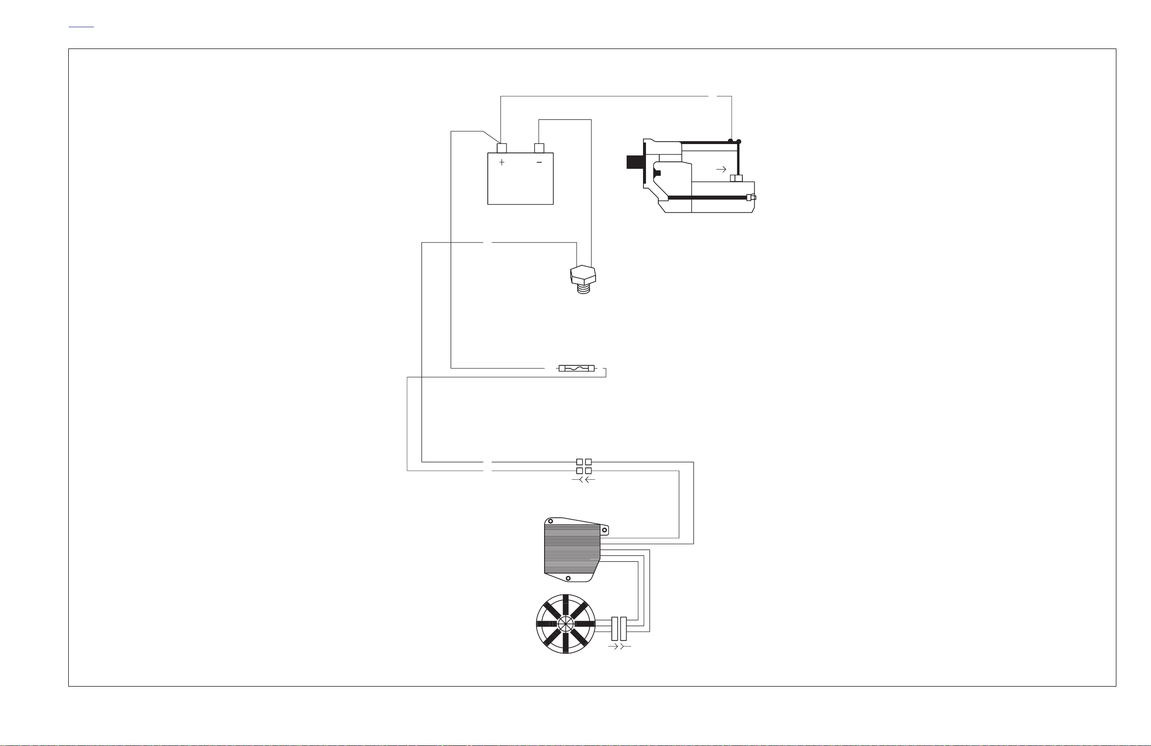
bs0021xx
BK
BATTERY
[GRD2]
BATTERY CABLE
BK
[128A]
STARTER
MOTOR
STARTER
SOLENOID
BK
R
VOLTAGE
REGULATOR
STATOR
(HD 3-PHASE)
FUSE/RELAY ASSEMBLY
BATTERY, 30A
R/Y
41
[61B]
R
35
TO VOLTAGE REGULATOR
11
2
2
[77B]
[77A]
[46A]
1
1
2
2
3
3
4
4
[46B]
2004 Lightning Models Charging Circuit
2004 Buell Lightning: Electrical B-22
Page 30
HOME
bs0020xx
TO MAIN HARNESS
O/W
W
Y
3
BK
4
HEADLIGHT
SUB-HARNESS(ES)
[38LA]
H7-55W
HI AND LO
BEAMS
[38HA]
[29A]
POSITION
LAMPS
(HDI ONLY)
MAIN HARNESS
FRONT TURN SIGNALS
LH TURN SIGNALS
V
1
BE
BK
2
BK
[31A]
RH TURN SIGNALS
[31A]
1
BK
2
1
BK
2
[29B]
O/W
1
2
BK
[31B]
111
BK
BK
222
BE
BN
[31B]
Y
W
FLASHER
[30A]
1
[30B]
O/W
V/BN
MAIN HARNESS
CLUTCH SW.
FRONT INJECTOR
42
54321
BK
[95A]
BRAKE SW.
[121A]
12
RH CONTROLS
BK/R
1
W/BK
2
[22B]
W/BK
3
GY
4
LH CONTROLS
Y
111
BE
222
33
W
Y/BK
44
Y/BK
55
BE/W
66
V
77
BN
88
21
O
[24B]
[24A]
REAR INJECTOR
[84A]
AA
BB
A
GY
W/Y
[84B]
[85A]
[85B]
A
BB
GY
GN/GY
HORN
[122A]
21
BK
Y/BK
[122B]
OIL PRESSURE SWITCH
1
1
GN/Y
[120B]
GN/Y
[120A]
ENGINE TEMP SENSOR
PK/Y
1
1
[90B]
[90A]
BATTERY
BK
FUSE/RELAY ASSEMBLY
BK
R
VOLTAGE
REGULATOR
STATOR
(HD 3-PHASE)
TAIL LAMP/REAR TURNING LIGHTS
BATTERY CABLE
[GRD2]
BATTERY, 30A
41
R/Y
[61B]
35
R
TO VOLTAGE REGULATOR
1
1
22
[46A]
[77A]
1
1
2
2
3
3
44
[46B]
TO MAIN HARNESS
[77B]
TAIL LIGHT
[93A]
BK
[128A]
STARTER
MOTOR
MUFFLER ACTUATOR
SUB-HARNESS
121
FUEL PUMP
STARTER
SOLENOID
Y0206.1AA
TO MAIN HARNESS
VEHICLE SPEED SENSOR
[65A]
MUFFLER VALVE ACTUATOR
POSITION
SENSOR
CONTROL ELECTRONICS
1432
1432
O
W
BK
[165B]
1
O
2
W
3
TN/V
LH TURN SIGNAL
LIC PLATE LAMP
RH TURN SIGNAL
[19A]
[45A]
[18A]
O/W
BE
1
BK
2
1
BK
2
BE
1
2
BK
A
WRB
BK
C
MTR
[161A]
TN/V
[161B]
TO MAIN HARNESS
BANK ANGLE SENSOR
11
22
33
R/W
BK/W
44
55
66
[134A]
LT.GN/GY
[134B]
Y/R
[89A]
1
2
INTAKE AIR TEMP
[89B]
12
BK/W
LT.GN/Y
UP
A
BK
B
BN/Y
C
GY
D
[86B]
LOW
FUEL
SENSOR
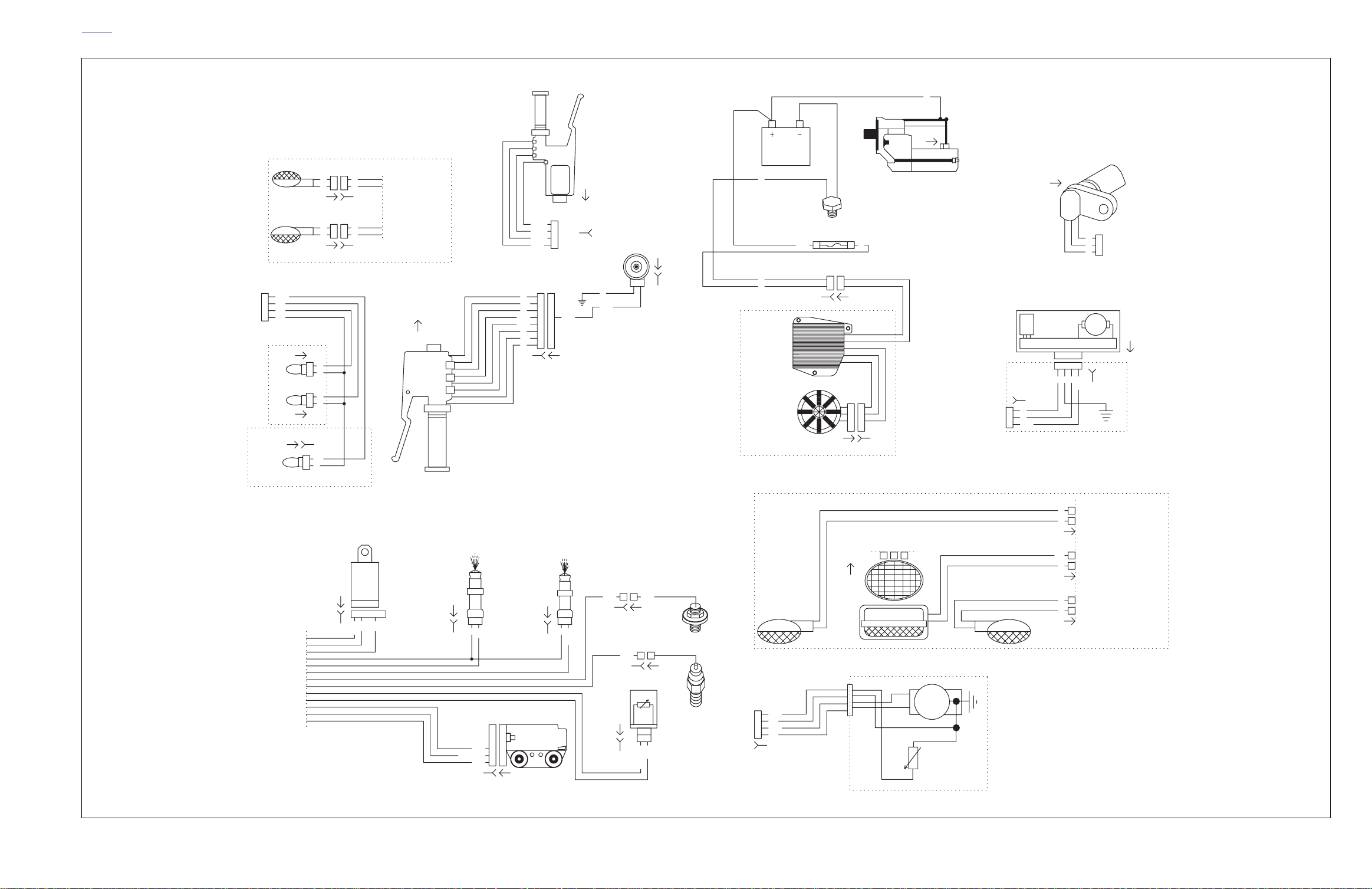
2004 Lightning Models Component Circuits
2004 Buell Lightning: Electrical B-23
MTR
Page 31
HOME
APPENDIX C–METRIC CONVERSIONS
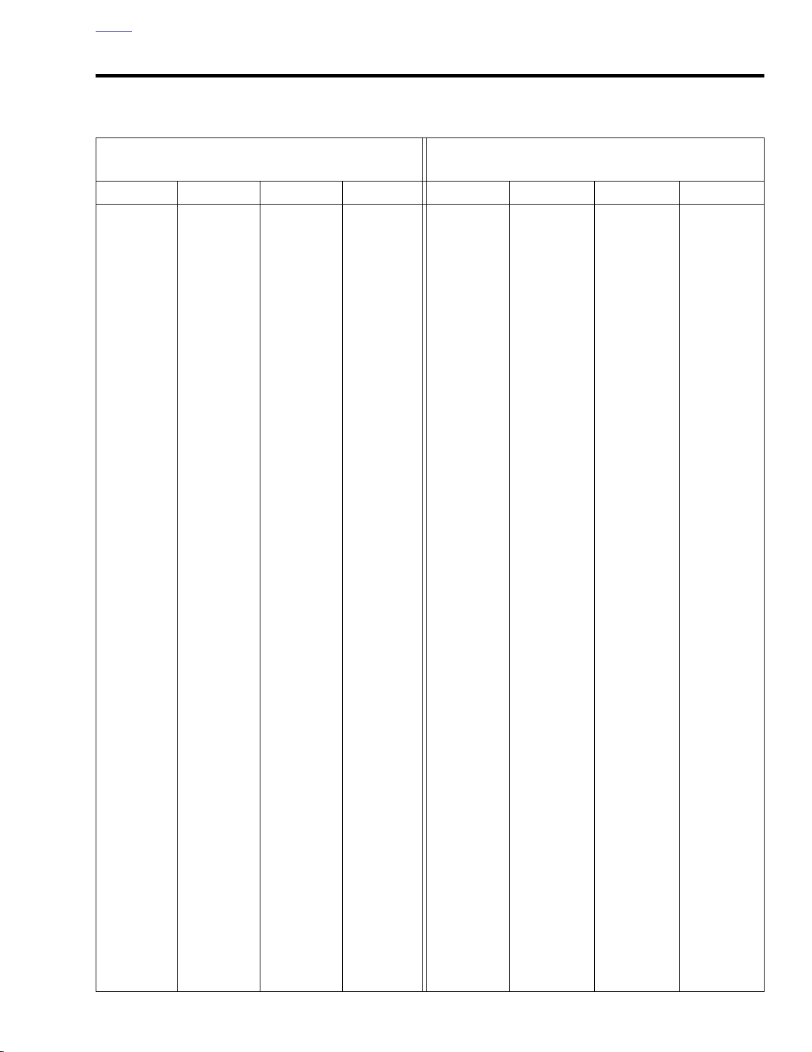
Table C-1. Metric Conversions
MILLIMETERS TO INCHES
(MM X 0.03937 = INCHES)
INCHES TO MILLIMETERS
(INCHES X 25.40 = MM)
mm in. mm in. mm in. mm in. in. mm in. mm in. mm in. mm
.1
.0039
25
.2
.0078
26
.3
.0118
27
.4
.0157
28
.5
.0197
29
.6
.0236
30
.7
.0275
31
.8
.0315
32
.9
.0354
33
1
.0394
34
2
.0787
35
3
.1181
36
4
.1575
37
5
.1968
38
6
.2362
39
7
.2756
40
.9842
1.024
1.063
1.102
1.142
1.181
1.220
1.260
1.299
1.338
1.378
1.417
1.456
1.496
1.535
1.575
58
59
60
61
62
63
64
65
66
67
68
69
70
71
72
73
2.283
2.323
2.362
2.401
2.441
2.480
2.519
2.559
2.598
2.638
2.677
2.716
2.756
2.795
2.834
2.874
91
92
93
94
95
96
97
98
99
100
101
102
103
104
105
106
3.582
3.622
3.661
3.701
3.740
3.779
3.819
3.858
3.897
3.937
3.976
4.016
4.055
4.094
4.134
4.173
.001
.002
.003
.004
.005
.006
.007
.008
.009
.010
1
/
64
.020
.030
1
/
32
.040
.050
.025
.051
.076
.102
.127
.152
.178
.203
.229
.254
.397
.508
.762
.794
1.016
1.270
.6
5
/
11
.7
3
/
.8
13
7
/
.9
15
1
1 1/
1.1
1 1/
1 3/
1.2
15.240
8
15.875
/
16
17.462
17.780
4
19.050
20.320
/
16
20.638
8
22.225
22.860
/
16
23.812
25.40
16
26.99
27.94
8
28.57
16
30.16
30.48
1
2
2 1/
2.1
2 1/
2 3/
2.2
2 1/
2.3
2 5/
2 3/
2.4
2 7/
2 1/
2 9/
2.6
15
/
16
49.21
3 5/
16
84.14
50.80
3 3/
8
85.72
16
52.39
3.4
53.34
3 7/
8
53.97
3 1/
16
55.56
3 9/
55.88
3.6
4
57.15
3 5/
58.42
3
16
58.74
3.7
8
60.32
3 3/
60.96
3.8
16
61.91
3
2
63.50
3 7/
16
65.09
3.9
66.04
3
11
13
15
16
2
16
8
/
4
/
8
/
16
16
16
86.36
87.31
88.90
90.49
91.44
92.07
93.66
93.98
95.25
96.52
96.84
98.42
99.06
100.01
10
11
12
13
14
15
16
17
18
19
20
21
22
23
24
8
.3149
41
9
.3543
42
.3937
43
.4331
44
.4724
45
.5118
46
.5512
47
.5905
48
.6299
49
.6693
50
.7086
51
.7480
52
.7874
53
.8268
54
.8661
55
.9055
56
.9449
57
1.614
1.653
1.693
1.732
1.772
1.811
1.850
1.890
1.929
1.968
2.008
2.047
2.086
2.126
2.165
2.205
2.244
74
75
76
77
78
79
80
81
82
83
84
85
86
87
88
89
90
2.913
2.953
2.992
3.031
3.071
3.110
3.149
3.189
3.228
3.268
3.307
3.346
3.386
3.425
3.464
3.504
3.543
107
108
109
110
111
112
113
114
115
116
117
118
119
120
121
122
123
4.212
4.252
4.291
4.331
4.370
4.409
4.449
4.488
4.527
4.567
4.606
4.645
4.685
4.724
4.764
4.803
4.842
.060
1
/
16
.070
.080
.090
.1
1
/
8
3
/
16
.2
1
/
4
.3
5
/
16
3
/
8
.4
7
/
16
1
/
2
9
/
16
1.524
1.588
1.778
2.032
2.286
2.540
3.175
4.762
5.080
6.350
7.620
7.938
9.525
10.160
11.112
12.700
14.288
1 1/
1.3
1 5/
1 3/
1.4
1 7/
1 1/
1 9/
1.6
1 5/
1
1.7
1 3/
1.8
1
1 7/
1.9
11
13
4
31.75
33.02
16
33.34
8
34.92
35.56
16
36.51
2
38.10
16
39.69
40.64
8
41.27
/
16
42.86
43.18
4
44.45
45.72
/
16
46.04
8
47.62
48.26
2 5/
2
2.7
2 3/
2.8
2
2 7/
2.9
2
3
3 1/
3.1
3 1/
3 3/
3.2
3 1/
3.3
11
13
15
8
66.67
4
101.6
/
16
68.26
4 1/
16
102.19
68.58
4.1
104.14
4
69.85
4 1/
8
104.77
71.12
4 3/
16
106.36
/
16
71.44
4.2
106.68
8
73.02
4 1/
4
107.95
73.66
4.3
109.22
/
16
74.61
4 5/
16
109.54
76.20
4 3/
8
111.12
16
77.79
4.4
111.76
78.74
4 7/
16
112.71
8
79.37
4 1/
2
114.30
16
80.96
4 9/
16
115.89
81.28
4.6
116.84
4
82.55
4 5/
8
117.47
83.82
11
4
/
16
119.06
2004 Buell Lightning: Appendix C C-1
Page 32

HOME
UNITED STATES SYSTEM
Unless otherwise specified,
in this Ser vice Manual are e xpressed in United States
(U.S.) units-of-measure.
●
1 pint (U.S.) = 16 fluid ounces ( .S.)
1 quart (U.S.) = 2 pints (U.S.) = 32 fl oz. (U.S.)
●
1 gallon (U.S.) = 4 quarts (U.S.) = 128 fl oz. (U.S.)
●
all fluid olume measurements
See below:
METRIC SYSTEM
Fluid volume measurements in this Ser vice Manual include
the metric system equivalents. In the metric system, 1 liter (L)
= 1,000 milliliters (mL). Should you need to convert from U.S.
units-of-measure to metr ic units-of-measure (or vice v ersa),
refer to the following:
●
fluid ounces ( .S.) x 29.574 = milliliters
pints (U.S.) x 0.473 = liters
●
quarts (U.S.) x 0.946 = liters
●
gallons (U.S.) x 3.785 = liters
●
●
milliliters x 0.0338 = fluid ounces ( .S.)
●
liters x 2.113 = pints (U.S.)
liters x 1.057 = quarts (U.S.)
●
liters x 0.264 = gallons (U.S.)
●
BRITISH IMPERIAL SYSTEM
Fluid volume measurements in this Ser vice Manual do not
include the British Imperial (Imp.) system equivalents. The following conversions exist in the British Imperial system:
●
1 pint (Imp.) = 20 fluid ounces (Im .)
1 quart (Imp.) = 2 pints (Imp.)
●
1 gallon (Imp.) = 4 quarts (Imp.)
●
Although the same unit-of-measure ter minology as the U .S.
system is used in the Br itish Imperial (Imp.) system, the
actual volume of each British Imperial unit-of-measure differs
from its U.S. counterpart. The U.S. fluid ounce is larger tha
the British Imperial fluid ounc . However, the U.S. pint, quart,
and gallon are smaller than the Br itish Imperial pint, quar t,
and gallon, respectiv ely. Should y ou need to con vert from
U.S. units to British Imperial units (or vice v ersa), refer to the
following:
●
fluid ounces ( .S.) x 1.042 = fluid ounces (Im .)
●
pints (U.S.) x 0.833 = pints (Imp.)
●
quarts (U.S.) x 0.833 = quarts (Imp.)
gallons (U.S.) x 0.833 = gallons (Imp.)
●
fluid ounces (Im .) x 0.960 = fluid ounces ( .S.)
●
●
pints (Imp.) x 1.201 = pints (U.S.)
●
quarts (Imp.) x 1.201 = quarts (U.S.)
gallons (Imp.) x 1.201 = gallons (U.S.)
●
C-2 2004 Buell Lightning: Appendix C
Page 33
HOME
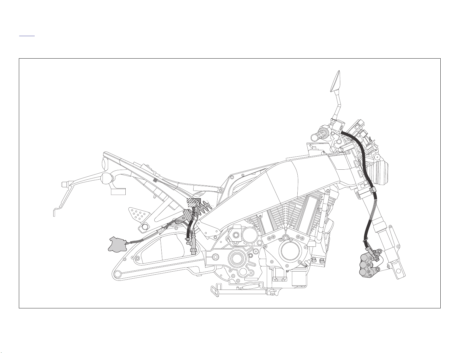
HOSE AND WIRE ROUTING
2004 Buell Lightning: Appendix D D-1
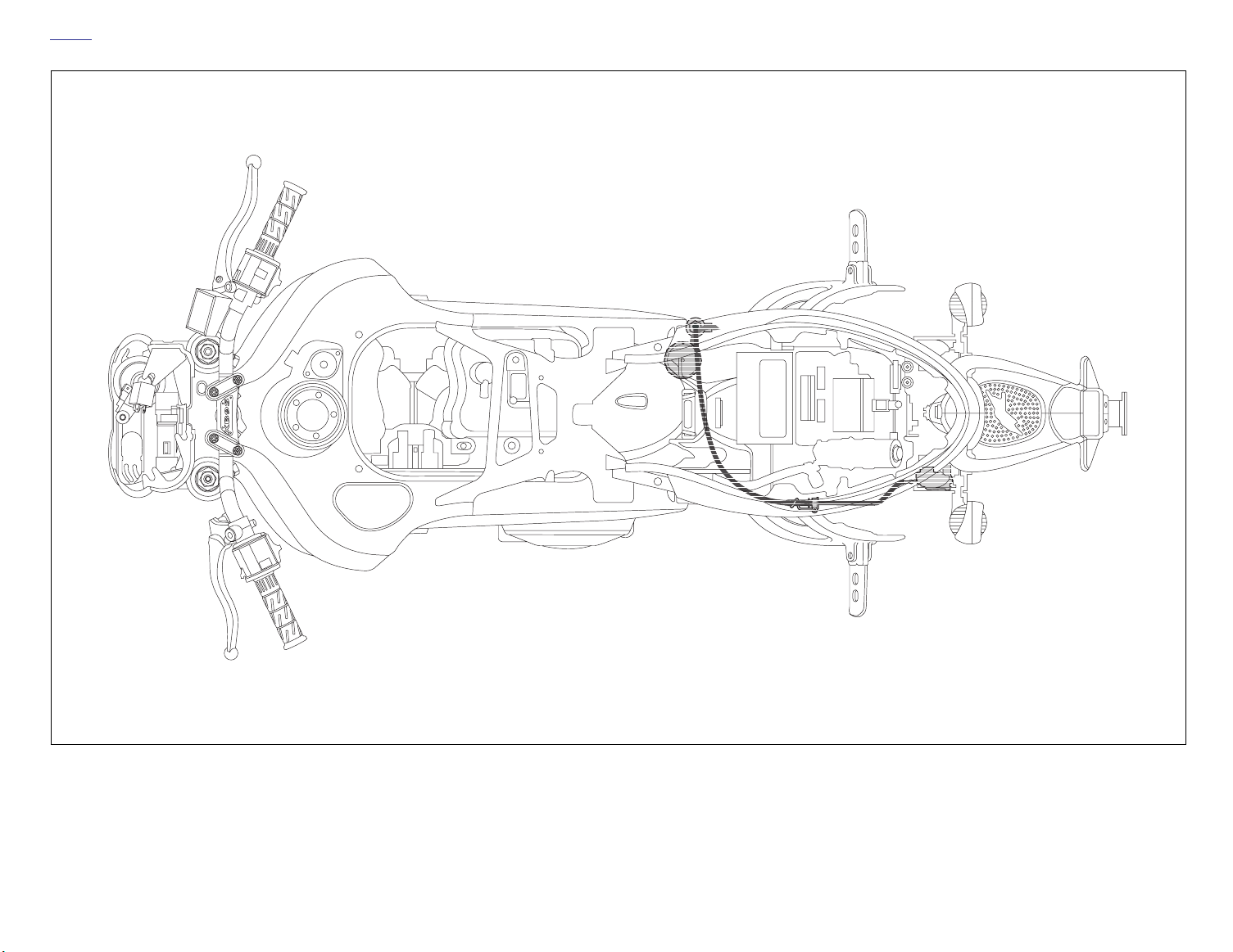
b1114xasx
Front and Rear Brake Systems, Right Side View
Page 34
HOME
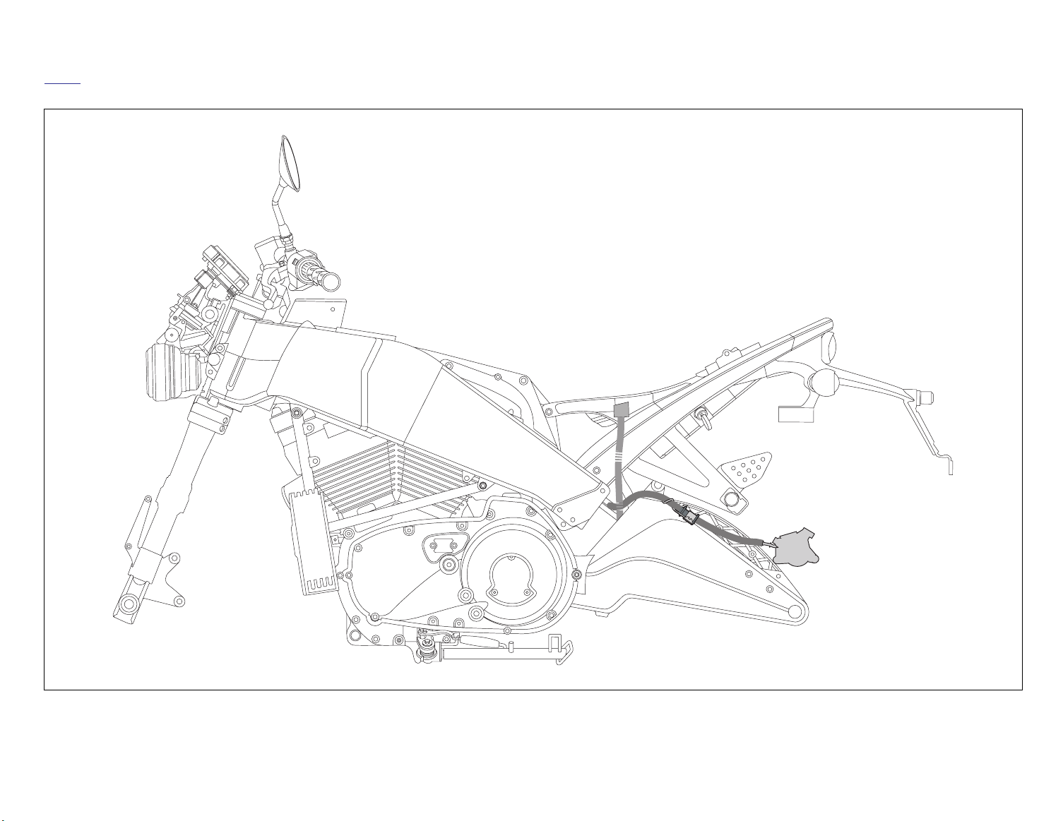
D-2 2004 Buell Lightning: Appendix D
b1115xbsx
Rear Brake Systems, Top View
Page 35
2004 Buell Lightning: Appendix D D-3
HOME
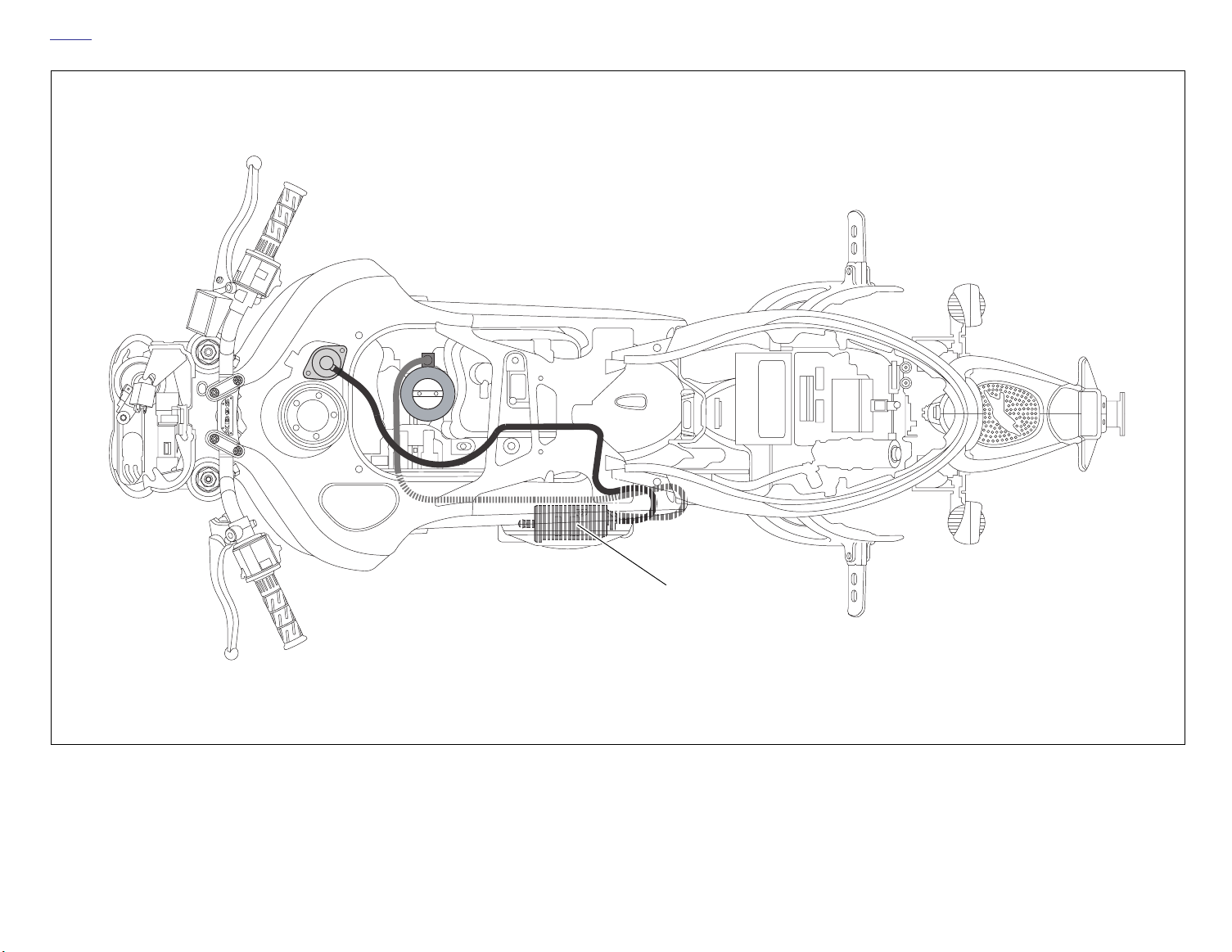
b1116xcsx
Rear Brake Systems, Left Side View
Page 36
HOME
D-4 2004 Buell Lightning: Appendix D
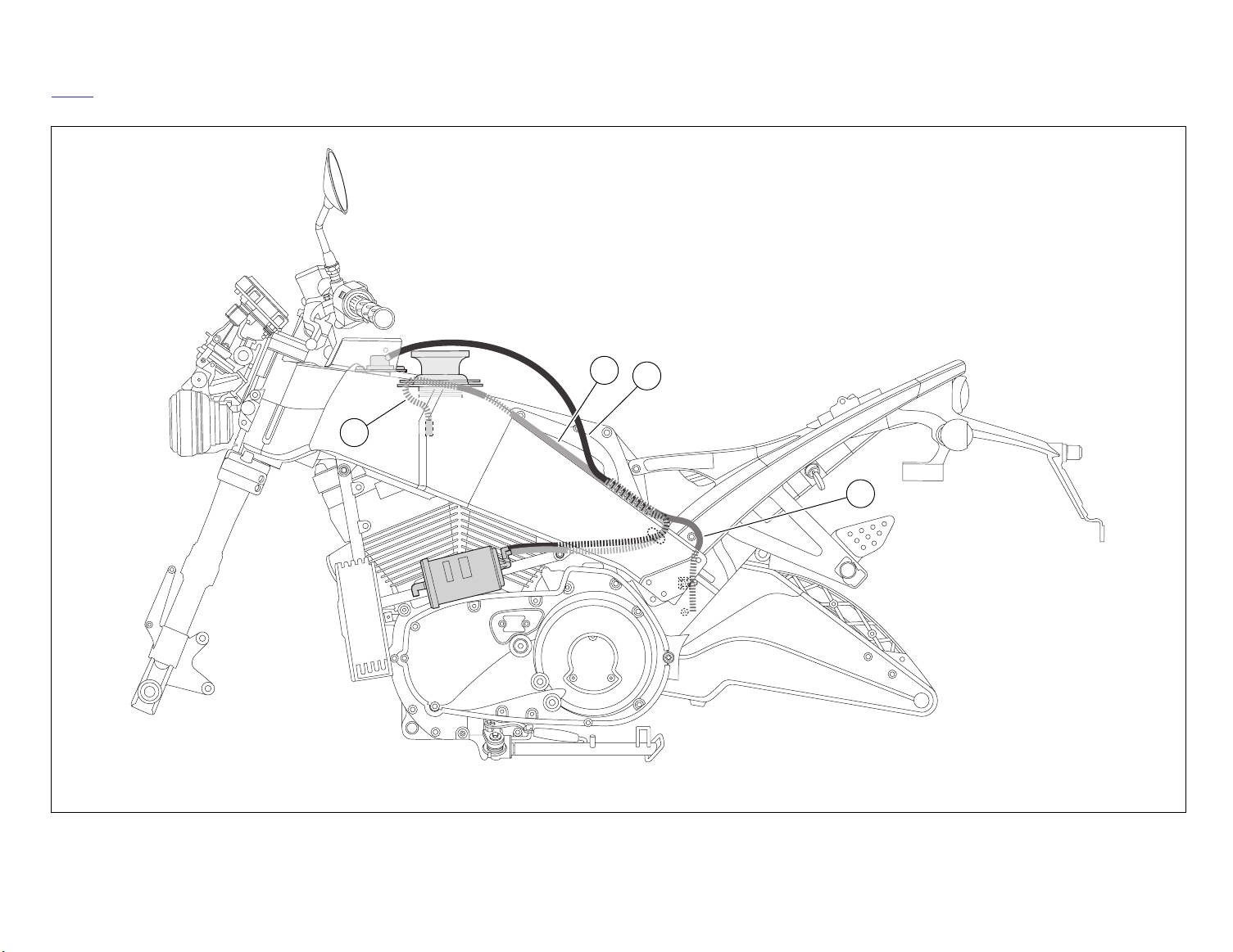
b1117xasx
Carbon canister
Evaporative Emissions Control, California Models, Top View
Page 37
2004 Buell Lightning: Appendix D D-5
HOME
b1118xbsx
2
3
1
4
1. To induction module
2. From induction module (California)
3. From fuel tank (California)
4. From fuel tank to atmosphere (49 state)
Evaporative Emissions Control, California and 49 State Models, Left Side View
Page 38
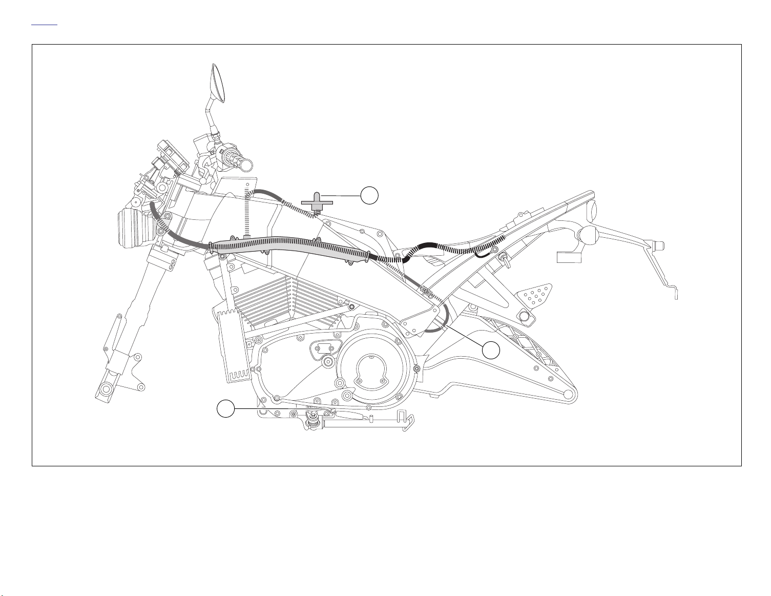
HOME
D-6 2004 Buell Lightning: Appendix D
b1119xasx
1
3
1. Intake air temperature sensor (IAT) 2. Fuel pump
Wiring Harness, Left Side View
2
Page 39
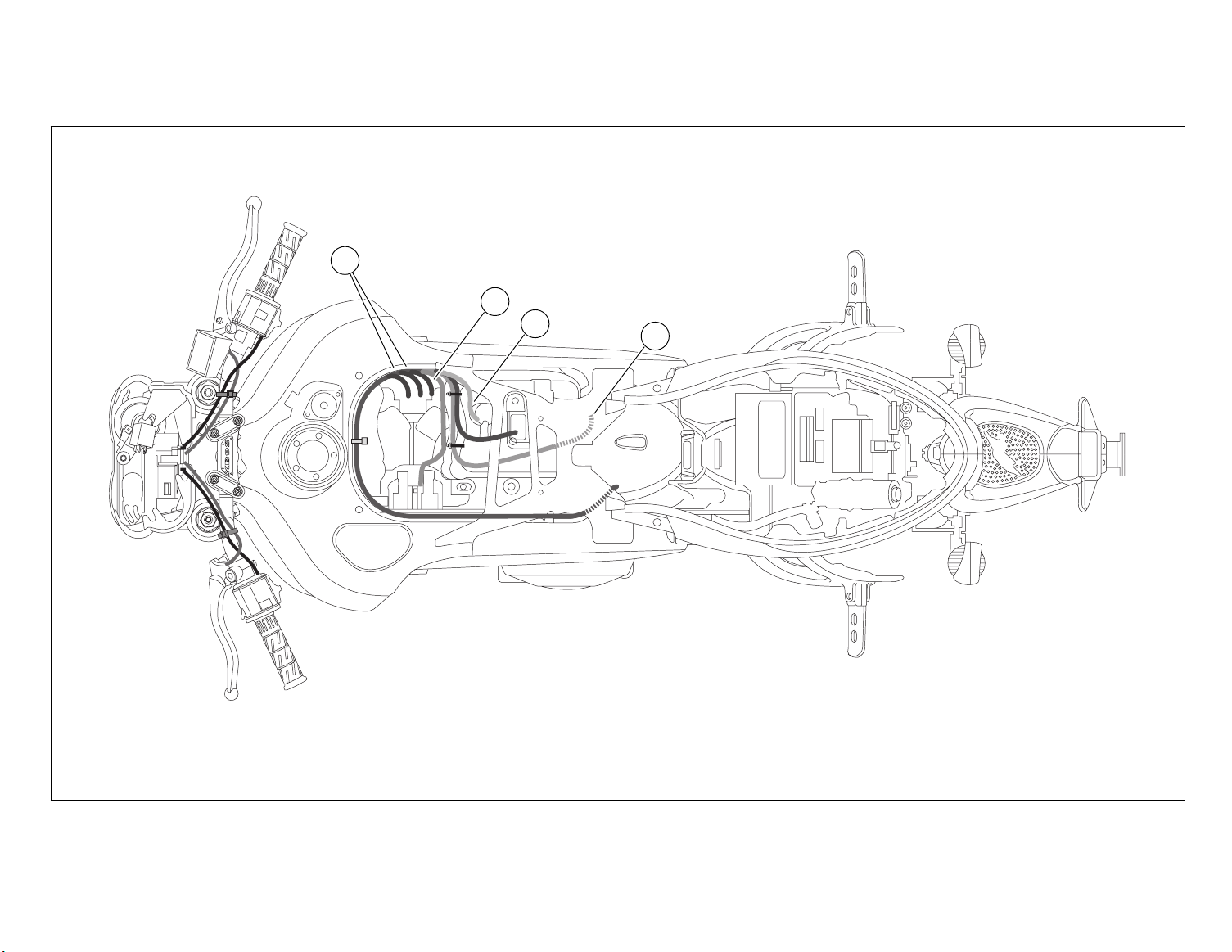
2004 Buell Lightning: Appendix D D-7
HOME
b1120xbsx
1
2
3
4
1. Fuel injector (2)
2. Throttle position sensor (TPS)
3. Intake air temperature (IAT) sensor
4. Oxygen (O2) sensor
Wiring Harness, Top View
Page 40
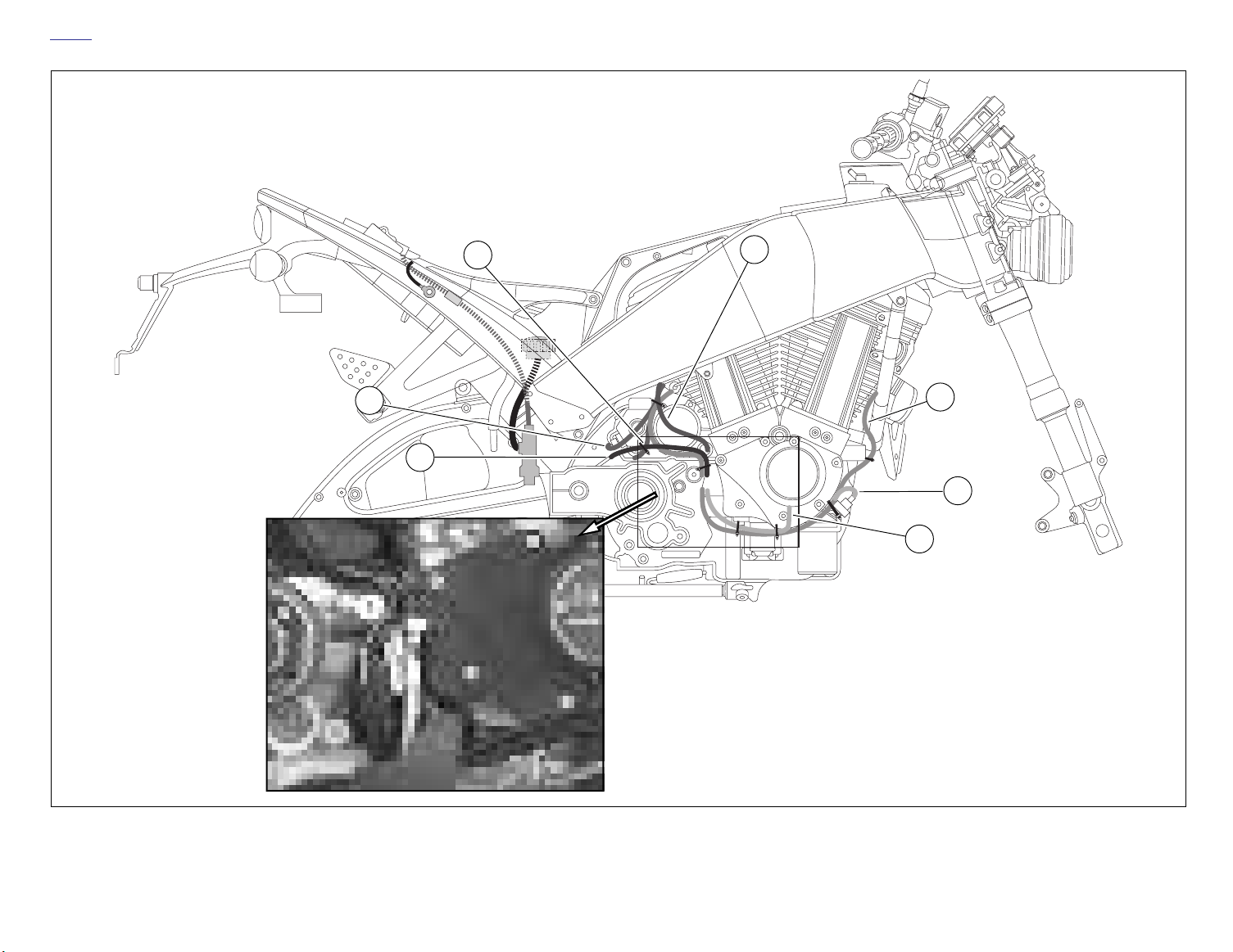
HOME
D-8 2004 Buell Lightning: Appendix D
b1121xcsx
3
2
4
5
1
6
7
1. Speedometer sensor
2. Cable, starter to battery positive
3. Solenoid
4. Transmission vent line
5. Voltage regulator
6. Switch, oil pressure
7. Cam position sensor
Wiring Harness, Right Side View
Page 41
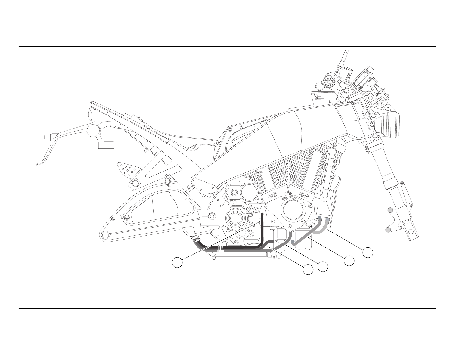
2004 Buell Lightning: Appendix D D-9
HOME
b1122xasx
1. Vent line
2. Feed oil line
3. Return oil line
5
1
4. Feed oil line from the oil pump to the oil cooler
5. Return oil line from the oil cooler to the oil filter housin
Oil Lines, Right Side View
3
2
4
Page 42
HOME
D-10 2004 Buell Lightning: Appendix D
b1123xbsx
2
3
1
1. Vent line 2. Feed oil line 3. Return oil line
Oil Lines, Bottom View
Page 43
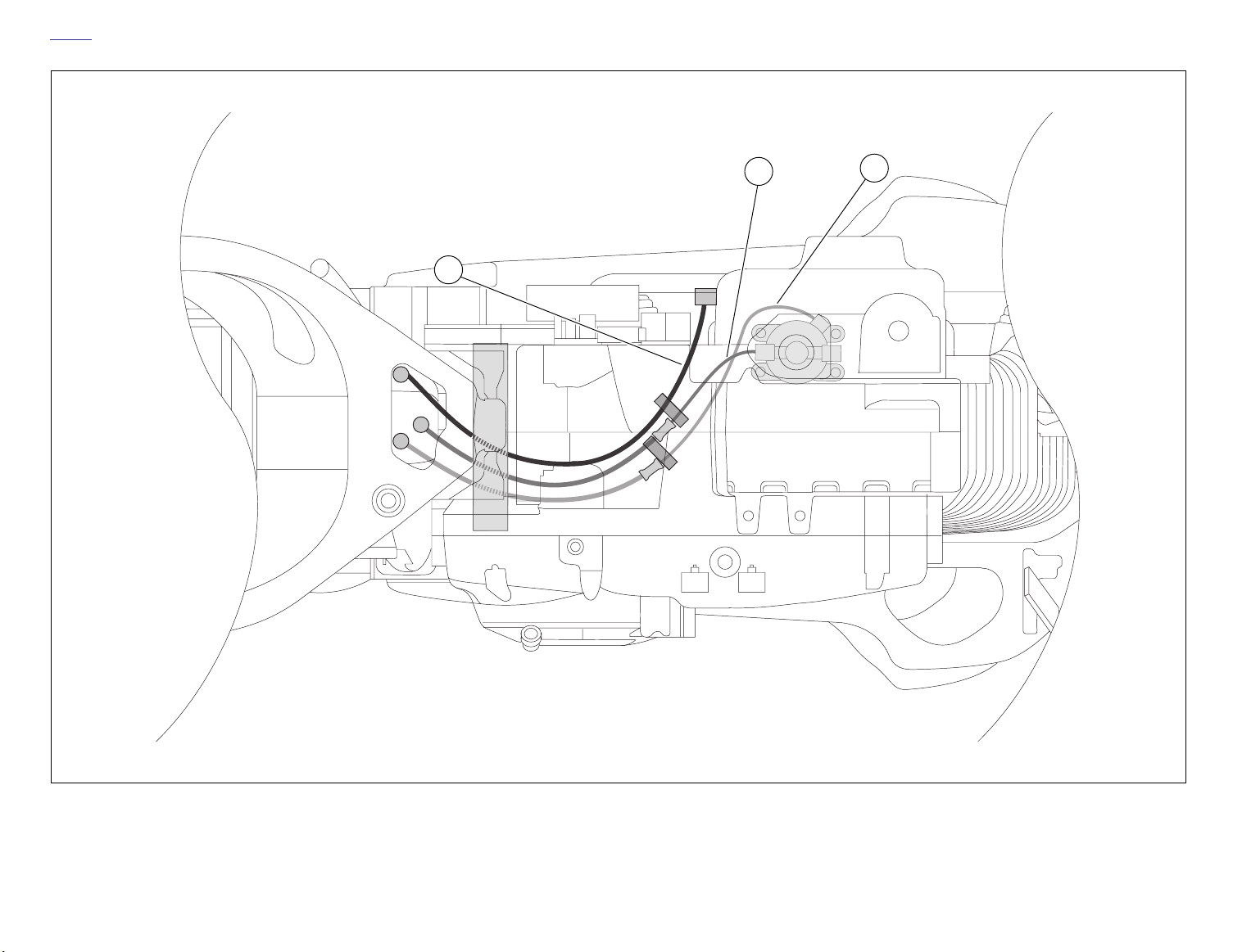
2004 Buell Lightning: Appendix D D-11
HOME
b1124xasx
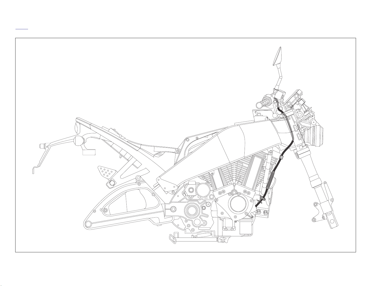
Clutch Cable, Right Side View
Page 44
HOME
D-12 2004 Buell Lightning: Appendix D
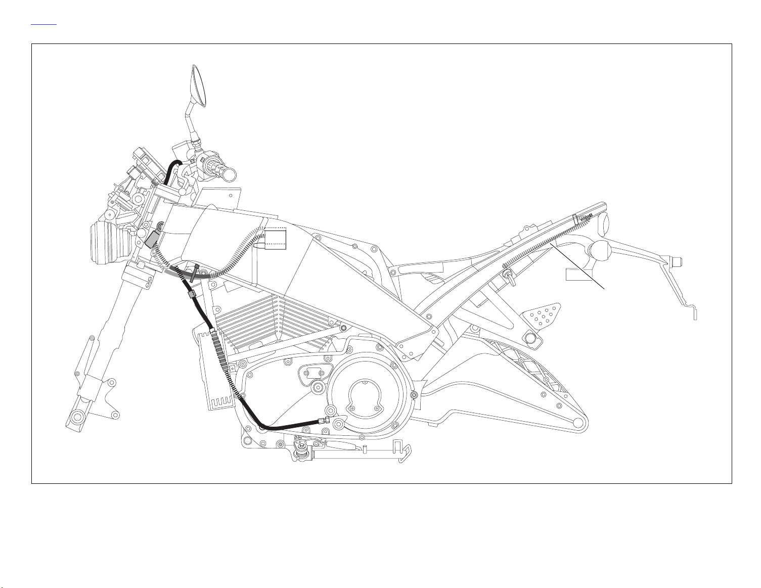
b1125xbsx
Cable, seat lock
Clutch, Throttle and Seat Release Cables, Left Side View
Page 45
2004 Buell Lightning: Appendix D D-13
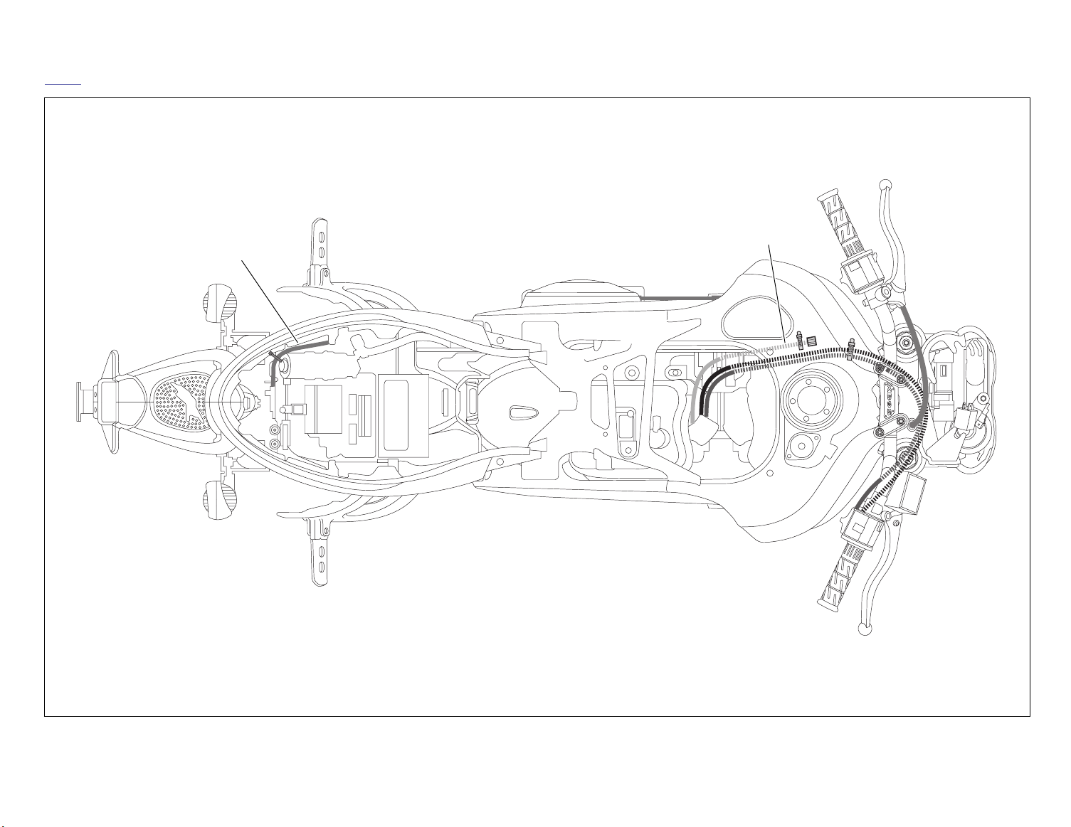
HOME
b1126xcsx
TPS adjuster
Cable, seat lock
Clutch, Throttle and Seat Release Cables, Top View
Page 46

HOME
NOTES
D-14 2004 Buell Lightning: Appendix D
Page 47
MAINTENANCE 1
T
able Of Contents
SUBJECT PAGE NO.
1.1 General . . . . . . . . . . . . . . . . . . . . . . . . . . . . . . . . . . . . . . . . . . . . . . . . . . . . . . 1-1
1.2 Fuel and Oil . . . . . . . . . . . . . . . . . . . . . . . . . . . . . . . . . . . . . . . . . . . . . . . . . . . 1-5
1.3 Maintenance Schedule . . . . . . . . . . . . . . . . . . . . . . . . . . . . . . . . . . . . . . . . . . 1-6
1.4 Care of Molded-in-Color Body Panels . . . . . . . . . . . . . . . . . . . . . . . . . . . . . . . 1-7
1.5 Battery Maintenance . . . . . . . . . . . . . . . . . . . . . . . . . . . . . . . . . . . . . . . . . . . . 1-8
1.6 Engine Lubrication System . . . . . . . . . . . . . . . . . . . . . . . . . . . . . . . . . . . . . . . 1-11
1.7 Brake System Maintenance . . . . . . . . . . . . . . . . . . . . . . . . . . . . . . . . . . . . . . . 1-14
1.8 Tires and Wheels . . . . . . . . . . . . . . . . . . . . . . . . . . . . . . . . . . . . . . . . . . . . . . . 1-22
1.9 Clutch . . . . . . . . . . . . . . . . . . . . . . . . . . . . . . . . . . . . . . . . . . . . . . . . . . . . . . . 1-23
1.10 Drive Belt Maintenance . . . . . . . . . . . . . . . . . . . . . . . . . . . . . . . . . . . . . . . . . 1-26
1.11 Primary Chain . . . . . . . . . . . . . . . . . . . . . . . . . . . . . . . . . . . . . . . . . . . . . . . . 1-29
1.12 Suspension Damping Adjustments . . . . . . . . . . . . . . . . . . . . . . . . . . . . . . . . 1-31
1.13 Steering Head Bearings . . . . . . . . . . . . . . . . . . . . . . . . . . . . . . . . . . . . . . . . 1-35
1.14 Spark Plugs . . . . . . . . . . . . . . . . . . . . . . . . . . . . . . . . . . . . . . . . . . . . . . . . . . 1-36
1.15 Air Cleaner Filter . . . . . . . . . . . . . . . . . . . . . . . . . . . . . . . . . . . . . . . . . . . . . . 1-38
1.16 Throttle Cable and Idle Speed Adjustment . . . . . . . . . . . . . . . . . . . . . . . . . . 1-40
1.17 Interactive Exhaust Cable Adjustment . . . . . . . . . . . . . . . . . . . . . . . . . . . . . . 1-41
1.18 Ignition Timing . . . . . . . . . . . . . . . . . . . . . . . . . . . . . . . . . . . . . . . . . . . . . . . . 1-43
1.19 Headlights . . . . . . . . . . . . . . . . . . . . . . . . . . . . . . . . . . . . . . . . . . . . . . . . . . . 1-45
1.20 Throttle Position Sensor (TPS) . . . . . . . . . . . . . . . . . . . . . . . . . . . . . . . . . . . 1-47
1.21 Storage . . . . . . . . . . . . . . . . . . . . . . . . . . . . . . . . . . . . . . . . . . . . . . . . . . . . . 1-48
1.22 Troubleshooting . . . . . . . . . . . . . . . . . . . . . . . . . . . . . . . . . . . . . . . . . . . . . . . 1-49
Page 48

Page 49

HOME
1WARNING1WARNING
GENERAL 1.1
SERVICING A NEW MOTORCYCLE
1WARNING1WARNING
Always follow the listed service and maintenance recommendations, because the y affect the saf e operation of
the motorcycle and the personal welfare of the rider. Failure to f ollow recommendations could result in death or
serious injury.
Service operations to be performed before customer delivery
are specified in the applica le model y ear PREDELIVERY
AND SETUP MANUAL.
The performance of new motorcycle initial service is required
to keep warranty in force and to ensure proper emissions systems operation. See 1.3 MAINTENANCE SCHEDULE for
details.
SAFE OPERATING MAINTENANCE
CAUTION
●
Do not attempt to retighten engine head bolts.
Retightening can cause engine damage.
SHOP PRACTICES
Repair Notes
NOTE
General maintenance practices are given in this section.
●
Repair = Disassembly/Assembly.
●
●
Replace = Removal/Installation.
All special tools and torque v alues are noted at the point of
use.
All required parts or materials can be found in the appropriate
PA RTS CATALOG.
Safety
Safety is always the most impor tant consideration when performing any job. Be sure you have a complete understanding
of the task to be perf ormed. Use common sense . Use the
proper tools. Protect y ourself and bystanders with approved
eye protection. Don’t just do the job – do the job safely.
Removing Parts
Always consider the weight of a part when lifting. Use a hoist
whenever necessary. Do not lift heavy parts by hand. A hoist
and adjustable lifting beam or sling are needed to remo ve
some parts. The lengths of chains or cables from the hoist to
the part should be equal and par allel and should be positioned directly o ver the center of the par t. Be sure that no
obstructions will interf ere with the lifting oper ation. Never
leave a part suspended in mid-air.
●
During the initial break-in period, use onl y HarleyDavidson 20W50 engine oil. Failure to use the recommended oil will result in impr oper break-in of the
engine cylinders and piston rings.
A careful check of certain equipment is necessary after periods of storage, and frequently betw een regular service intervals, to determine if additional maintenance is required.
Check:
1. Tires for abrasions, cuts and correct pressure.
2. Secondary drive belt for proper tension and condition.
3. Brakes, steering and throttle for responsiveness.
4. Brake fluid l vel and condition. Hydraulic lines and fit
tings for leaks. Also, check brake pads and rotors f or
wear.
5. Cables for fraying, crimping and free operation.
6. Engine oil and transmission fluid l vels.
7. Headlamp, passing lamp, tail lamp, brake lamp and turn
signal operation.
Always check the capacity rating and condition of hoists,
slings, chains or cables before use. Failure to do so can
lead to an accident which could result in death or serious
injury.
Always use blocking or proper stands to support the part that
has been hoisted. If a par t cannot be removed, verify that all
bolts and attaching hardw are have been remo ved. Check to
see if any parts are in the way of the part being removed.
When removing hoses, wiring or tubes, always tag each par t
to ensure proper installation.
Cleaning
If you intend to reuse par ts, follow good shop pr actice and
thoroughly clean the par ts before assembly. Keep all dirt out
of parts; the unit will perform better and last longer. Seals, fil
ters and covers are used in this v ehicle to keep out environmental dirt and dust. These items m ust be k ept in good
condition to ensure satisfactory operation.
Clean and inspect all par ts as they are removed. Be sure all
holes and passages are clean and open. After cleaning,
cover all par ts with clean lint-free cloth, paper or other material. Be sure the part is clean when it is installed.
Always clean around lines or covers before they are removed.
Plug, tape or cap holes and openings to k eep out dir t, dust
and debris.
2004 Buell Lightning: Maintenance 1-1
Page 50

HOME
Disassembly and Assembly
Always assemble or disassemble one part at a time . Do not
work on two assemblies simultaneously. Be sure to mak e all
necessary adjustments. Recheck your work when finished
Be sure that everything is done.
Operate the v ehicle to perf orm any final che k or adjustments. If all is correct, the v ehicle is ready to go bac k to the
customer.
REPAIR AND REPLACEMENT
PROCEDURES
Hardware and Threaded Parts
Install helical thread inser ts when inside threads in castings
are stripped, damaged or not capab le of withstanding specified torqu .
Replace bolts, nuts, studs, washers, spacers and small common hardware if missing or in any way damaged. Clean up or
repair minor thread damage with a suitable thread chaser.
Replace all damaged or missing lubrication fitting .
Use Teflon pipe sealant on pipe fitting threa .
Wiring, Hoses and Lines
Replace hoses, clamps, electrical wiring, electrical switches
or fuel lines if they do not meet specification .
Bushings
Do not remove a bushing unless damaged, excessively worn
or loose in its bore. Press out bushings that must be replaced.
When pressing or driving bushings, be sure to apply pressure
in line with the b ushing bore. Use a bear ing/bushing driver or
a bar with a smooth, flat end Never use a hammer to dr ive
bushings.
Inspect the bushing and the mated par t for oil holes. Be sure
all oil holes are properly aligned.
Gaskets
Always discard gaskets after removal. Replace with
kets. Never use the same gask et twice. Be sure that gask et
holes match up with holes in the mating part.
new
gas-
Lip Type Seals
Lip seals are used to seal oil or g rease and are usually
installed with the sealing lip f acing the contained lubr icant.
Seal orientation, however, may vary under diff erent applications.
Seals should not be removed unless necessary. Only remove
seals if required to gain access to other par ts or if seal damage or wear dictates replacement.
Leaking oil or g rease usually means that a seal is damaged.
Replace leaking seals to prevent overheated bearings.
Always discard seals after removal. Do not use the same seal
twice.
Instruments and Gauges
Replace broken or def ective instruments and gauges .
Replace dials and glass that are so scr atched or discolored
that reading is difficult
Bearings
Anti-friction bearings must be handled in a special w ay. To
keep out dir t and abr asives, cover the bearings as soon as
they are removed from the package.
Wash bearings in a non-flamma le cleaning solution. Knock
out packed lubricant inside by tapping the bear ing against a
wooden block. Wash bearings again. Cover bearings with
clean material after setting them down to dry. Never use compressed air to dry bearings.
Coat bearings with clean oil. Wrap bearings in clean paper.
Be sure that the chamf ered side of the bear ing always faces
the shoulder (when bear ings installed against shoulders).
Lubricate bearings and all metal contact surf aces before
pressing into place . Only apply pressure on the par t of the
bearing that makes direct contact with the mating par t. Install
bearings with numbered side facing out.
Always use the proper tools and fixtures or removing and
installing bearings.
Bearings do not usually need to be remo ved. Only remo ve
bearings if necessary.
O-Rings (Preformed Packings)
Always discard O-r ings after remo val. Replace with
rings. To prevent leaks, lubricate the O-r ings before installation. Apply the same type of lubr icant as that being sealed.
Be sure that all gask et, O-ring and seal mating surf aces are
thoroughly clean before installation.
new
O-
Gears
Always check gears for damaged or worn teeth.
Lubricate mating surfaces before pressing gears on shafts.
Shafts
If a shaft does not come out easily , check that all n uts, bolts
or retaining r ings have been removed. Check to see if other
parts are in the way before using force.
Shafts fitted to tapered splines should be ery tight. If shafts
are not tight, disassemb le and inspect tapered splines . Discard parts that are w orn. Be sure tapered splines are clean,
dry and free of burrs before putting them in place. Press mating parts together tightly.
Clean all rust from the machined surfaces of new parts.
Part Replacement
Always replace worn or damaged parts with
new
parts.
1-2 2004 Buell Lightning: Maintenance
Page 51

HOME
CLEANING
Part Protection
Before cleaning, protect r ubber parts (such as hoses , boots
and electrical insulation) from cleaning solutions . Use a
grease-proof barrier material. Remove the r ubber part if it
cannot be properly protected.
Cleaning Process
Any cleaning method ma y be used as long as it does not
result in par ts damage. Thorough cleaning is necessar y for
proper parts inspection. Strip rusted paint areas to bare metal
before repainting.
Rust or Corrosion Removal
Remove rust and corrosion with a wire br ush, abrasive cloth,
sand blasting, vapor blasting or rust remover. Use buffing crocus cloth on highly polished parts that are rusted.
TOOL SAFETY
Air Tools
●
Always use appro ved eye protection equipment when
performing any task using air-operated tools.
On all po wer tools, use only recommended accessor ies
●
with proper capacity ratings.
Do not exceed air pressure ratings of any power tools.
●
●
Bits should be placed against w ork surface before air
hammers are operated.
Disconnect the air supply line to an air hammer bef ore
●
attaching a bit.
Never point an air tool at yourself or another person.
●
●
Protect bystanders with approved eye protection.
Hammers
Never strike one hammer against a hardened object,
●
such as another hammer.
●
Always grasp a hammer handle fi mly, close to the end.
●
Strike the object with the full face of the hammer.
●
Never work with a hammer which has a loose head.
●
Discard hammer if face is chipped or mushroomed.
Wear approved eye protection when using striking tools.
●
Protect bystanders with approved eye protection.
●
Punches/chisels
●
Never use a punch or chisel with a chipped or m ushroomed end; dress m ushroomed chisels and punches
with a fil .
Hold a chisel or a punch with a tool holder if possible.
●
●
When using a chisel on a small piece , clamp the piece
fi mly in a vise and chip toward the stationary jaw.
●
Wear approved eye protection when using these tools.
●
Protect bystanders with approved eye protection.
Screwdrivers
●
Don’t use a scre wdriver for prying, punching, chiseling,
scoring or scraping.
●
Use the right type of screwdriver for the job; match the tip
to the fastener.
Don’t interchange POZIDRIV®, PHILLIPS® or REED
●
AND PRINCE screwdrivers.
Wrenches
●
Never use an extension on a wrench handle.
If possible, always pull on a wrench handle and adjust
●
your stance to prevent a fall if something lets go.
Never cock a wrench.
●
●
Never use a hammer on any wrench other than a STRIKING FACE wrench.
Discard any wrench with broken or battered points.
●
●
Never use a pipe wrench to bend, raise or lift a pipe.
Pliers/cutters/prybars
Plastic- or vinyl-covered pliers handles are not intended
●
to act as insulation; don’t use on live electrical circuits.
●
Don’t use pliers or cutters f or cutting hardened wire
unless they were designed for that purpose.
Always cut at right angles.
●
●
Don’t use any prybar as a chisel, punch or hammer.
●
Screwdriver handles are not intended to act as insulation; don’t use on live electrical circuits.
●
Don’t use a scre wdriver with rounded edges because it
will slip – redress with a fil .
Ratchets and Handles
●
Periodically clean and lubricate ratchet mechanisms with
a light grade oil. Do not replace par ts individually; ratchets should be reb uilt with the entire contents of ser vice
kit.
●
Never hammer or put a pipe e xtension on a r atchet or
handle for added leverage.
●
Always support the r atchet head when using soc ket
extensions, but do not put your hand on the head or y ou
may interfere with the action of its reversing mechanism.
When breaking loose a fastener, apply a small amount of
●
pressure as a test to be sure the r atchet’s gear wheel is
engaged with the pawl.
2004 Buell Lightning: Maintenance 1-3
Page 52

HOME
Sockets
●
Never use hand sockets on power or impact wrenches.
Select the right size socket for the job.
●
Never cock any wrench or socket.
●
●
Select only impact soc kets for use with air or electr ic
impact wrenches.
●
Replace sockets showing cracks or wear.
Keep sockets clean.
●
●
Always use approved eye protection when using po wer
or impact sockets.
Storage Units
●
Don’t open more than one loaded dr awer at a time .
Close each drawer before opening up another.
●
Close lids and loc k drawers and doors bef ore moving
storage units.
●
Don’t pull on a tool cabinet; push it in front of you.
Set the br akes on the loc king casters after the cabinet
●
has been rolled to your work.
1-4 2004 Buell Lightning: Maintenance
Page 53

HOME
FUEL AND OIL 1.2
FUEL
1WARNING1WARNING
Remove filler cap sl wly and fill fuel tank sl wly to prevent
spillage; do not overfill or fill ab ve the bottom of the fille
neck insert. In ad dition, leave air space to allo w for fuel
expansion. Expansion can cause an o verfilled tank to
overfl w gasoline through the filler cap onto sur ounding
areas. After refueling, be sure filler cap is secure y tightened. Failure to compl y may cause an e xplosion or fir
which could result in death or serious injury.
Use a good quality unleaded gasoline (91 pump octane or
higher). Pump octane is the octane number usually shown on
the gas pump.
GASOLINE BLENDS
CAUTION
Using gasoline that has an alcohol ad ditive, such as
methanol, may cause fuel system rubber components’
failure and/or engine damage.
Buell motorcycles w ere designed to giv e the best perf ormance using unleaded gasoline . Some fuel suppliers sell
gasoline/alcohol blends as a fuel. The type and amount of
alcohol added to the fuel is important.
ENGINE OIL
Use the proper g rade of oil f or the lo west temperature
expected before the next oil change.
If it is necessar y to add oil and Har ley-Davidson oil is not
available, use an oil cer tified for diesel engines . Acceptable
diesel engine oil designations include CF-4, CG-4, CH-4 and
CI4. The preferred viscosities f or the diesel engine oils , in
descending order, are 20W-50, 15W-40 and 10W -40. At the
first opportunity, see a Har ley-Davidson dealer to change
back to 100 percent Harley-Davidson oil.
See 1.6 ENGINE LUBRICA TION SYSTEM for all ser vice
information.
WINTER LUBRICATION
Combustion in an engine produces w ater vapor. During starting and warm-up in cold w eather, especially in freezing temperatures, the v apor condenses to w ater before the
crankcase is hot enough to e xhaust it through the breather
system. If the engine is run long enough for the crankcase to
become thoroughly heated, the w ater returns to vapor and is
then exhausted.
An engine used f or only shor t trips, and seldom allo wed to
thoroughly warm up, accumulates increasing amounts of
water in the oil pan. Water mixed with oil forms a sludge that
causes accelerated engine w ear. In freezing temper atures,
the water becomes slush or ice , which may clog oil lines and
result in engine failure.
Always change the engine oil more often in winter . If the
engine is used f or short runs, change the oil e ven more frequently. The farther below freezing the temperature drops the
more often the oil should be changed.
●
DO NOT USE GASOLINES CONTAINING METHANOL.
Using gasoline/methanol blends will result in starting and
driveability deterioration and damage to cr itical fuel system components.
ETHANOL is a mixture of 10% ethanol (Gr ain alcohol)
●
and 90% unleaded gasoline . Gasoline/ethanol b lends
can be used in y our motorcycle if the ethanol content
does not exceed 10%.
●
REFORMULATED OR O XYGENATED GASOLINES
(RFG): “Reformulated gasoline” is a ter m used to
describe gasoline blends that are specifically designed t
burn cleaner than other types of gasoline . Your motorcycle will run normally using this type of gas.
Yo u may find that some gasoline lends adversely affect the
starting, driveability or fuel efficiency of our bike. If you experience one or more of these problems, we recommend you try
a different brand of gasoline or gasoline with a higher octane
rating.
2004 Buell Lightning: Maintenance 1-5
Page 54
HOME
MAINTENANCE SCHEDULE 1.3
Table 1-1. Regular Service Intervals
1
1
2
2
3
3
4
4
km
5
5
0
0
0
0
0
0
0
mi
mi
7
8
2
0
0
0
0
0
0
0
km
1
5
0
5
0
5
0
5
ODOMETER READING
SERVICE OPERATIONS
(See Chart Code Below)
mi
km
0
0
0
0
0
0
mi
km
0
0
0
0
0
mi
4
4
0
8
0
0
0
0
0
0
km
0
0
0
0
km
0
0
0
mi
mi
2
3
4
2
0
0
0
0
0
0
km
0
0
0
mi
mi
km
1
8
6
0
0
0
0
0
0
km
1
6
0
0
mi
km
0
0
0
0
0
0
0
mi
5
6
6
4
0
0
0
0
0
0
km
Change engine oil and filter. R RRRRRRRRRR
Inspect air cleaner, service as required. IIIIRIIIRII
Inspect brake pads and rotors for wear. IIIIIIIIIII
Adjust primary chain. AAAAAAAAAAA
Change transmission/primary chaincase lube and clean drain plug. RI RI RI RI RI RI RI RI RI RI RI
Check ignition timing. IIIII
Replace spark plugs. RRRRR
Zero throttle position sensor (TPS). AAAAAA
Check engine idle speed. IIIIIIIIIII
Steering head bearing resistance test. XXXXXXXXXX
Adjust throttle cables. AAAAAAAAAAA
Adjust clutch and clutch cable. AAAAAAAAAAA
Check rear belt and idler pulley.
Replace belt and idler pulley every 25,000 mi. (40,000 km).
IIIIIRIIIIR
Check front and rear tire pressure and inspect tread. IIIIIIIIIII
Clean oil cooler fins. XXXXXXXXXXX
Change front fork oil. XXXXX
Check brake fluid reservoir levels and condition. IIIIIIIIIII
Inspect front and rear brake caliper and master cylinder for leaks every 5000 miles (8000
km) or two years.
IIIIIIIIII
Check operation of all electrical equipment & switches. IIIIIIIIIII
Inspect oil lines and brake system for leaks. IIIIIIIIIII
Lubricate front brake hand lever, throttle control cables, clutch control cables (and hand
lever), sidestand pivot, and rear brake pedal bushing (if applicable).
IL IL IL IL IL IL IL IL IL IL IL
Check tightness of all critical fasteners: hand controls, brake system, front and rear axles,
upper and lower triple clamps, front fork components, engine mounts, stabilizers, rear
TTTTT
shock.
Inspect motorcycle: Check front and rear brake lines, oil lines, front forks, rear shock,
exhaust system, exhaust system mounting.
XXXXXXXXXXX
Road test. XXXXXXXXXXX
Chart Codes:
I
- Inspect, & if necessary correct, clean or replace.
L
- Lubricate with specified lubricant.
R
- Replace or change.
T
- Tighten to proper
A
- Adjust.
X
- Perform.
torque.
1-6 2004 Buell Lightning: Maintenance
Page 55

HOME
CARE OF MOLDED-IN-COLOR BODY PANELS 1.4
GENERAL
Special care and maintenance are required for the molded-incolor body panels that are standard on your Buell motorcycle.
Molded-in-color surfaces look lik e painted surf aces, but are
not. The color pigment is mixed in with the material when the
part is made , not applied o ver the surf ace. Molded-in-color
panels require different maintenance than painted surfaces to
maintain their or iginal shine. Using methods that w ork on
painted surfaces may ruin the finish of molded-in-color pa ts.
CAUTION
Use of abrasive pr oducts or powered buffing equipment
will cause permanent cosmetic dama ge to molded-incolor body panels. Use only the recommended pr oducts
and techniques outlined in this section to a void damaging molded-in-color body panels.
CAUTION
Do not use touch-up paint on molded-in-color panels.
Cleaning Between Washings
Untreated molded-in-color body panels sometimes ha ve a
static charge that attracts dust. Applying Harley Gloss or Harley Glaze Polish and Sealant to molded-in-color surf aces will
eliminate this condition.
To k eep a high gloss finish on molded-in-color panel
between washings:
1. Spray Harley Gloss onto surf ace and wipe with a clean
soft natural fiber cloth or Ha ley Softcloth.
NOTE
Rain or water will remove Harley Gloss from body panels.
2. Reapply Harley Gloss as descr ibed above to keep surfaces looking their best.
Polishing
Polishing molded-in-color body panels results in g reater surface gloss and a protective coating.
RECOMMENDED PRODUCTS
Products recommended for the proper care and maintenance
of molded-in-color body panels are a vailable at y our Buell
dealer and are listed below:
Harley Wash (Part No. 99715-90) or Har ley Sun Wash
●
(Part No. 94659-98)
●
Harley Gloss (Part No. 94627-98)
Harley Glaze Polish and Sealant (Part No. 99704-84)
●
●
Harley Swirl and Scratch Treatment (Part No. 94655-98)
Harley Softcloth (Part No. 94656-98)
●
CARE AND MAINTENANCE
Washing
To wash molded-in-color panels:
1. Rinse surface with water.
1. Apply Harley Glaze Polish and Sealant every six months
or as required to k eep molded-in-color panels protected
and looking their best.
2. Clean and dry surfaces to be polished (see
3. Apply Harley Glaze Polish and Sealant to clean, slightly
dampened cloth or sponge and apply to surf ace with a
light overlapping motion. Make sure to cover all areas.
4. Let Harley Glaze Polish and Sealant dr y to a haz e and
buff off residue with a clean soft cloth or Harley Softcloth.
Washing
).
Minor Scratch Removal
To remove minor scratches from body panels:
1. To remove light surf ace scratches and rubs, use Harley
Swirl and Scratch Treatment as recommended.
2. Make sure Swirl and Scratch Treatment is applied with a
moist cloth and by hand (not by machine).
3. After scratch or r ub has been repaired, polish surf ace
lightly with Harley Glaze.
2. Wash with Harley Wash or Harley Sun Wash.
3. Rinse surface thoroughly with water.
4. Dry with a clean chamois or soft dry natural fiber cloth
Major Scratches
There is no repair procedure f or severely scratched surfaces.
Severely scratched body panels must be replaced.
2004 Buell Lightning: Maintenance 1-7
Page 56
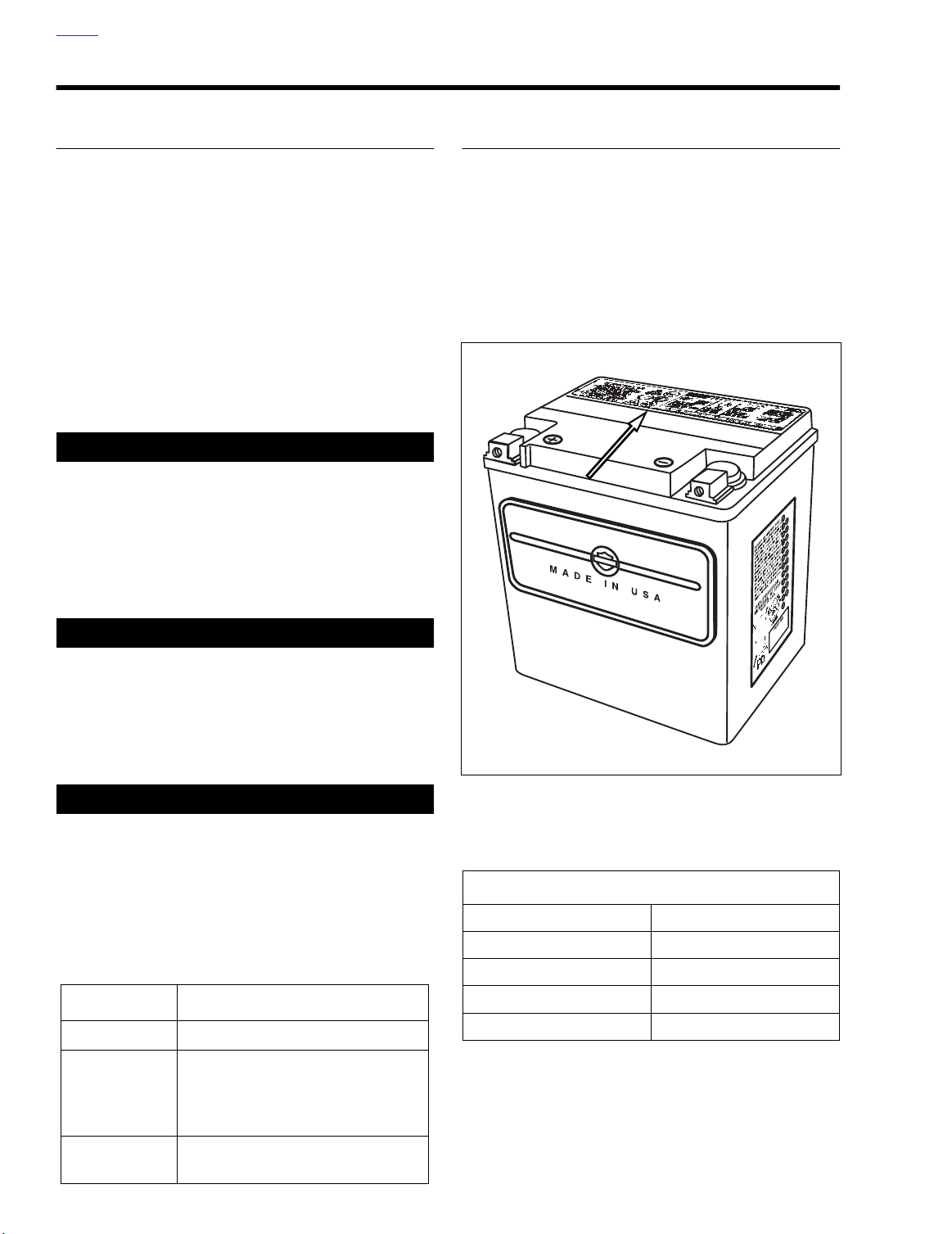
HOME
BATTERY MAINTENANCE 1.5
GENERAL
Buell motorcycle batter ies are per manently sealed, maintenance-free, valve-regulated, lead/calcium and sulfur ic acid
batteries. The batteries are shipped pre-charged and ready to
be put into service. Do not attempt to open these batteries for
any reason.
Inspect the batter y for damage or leaks and f or clean, noncorroded connections:
●
At the 1000 mile (1600 km) service interval.
At every scheduled service interval thereafter.
●
1WARNING1WARNING
All batteries contain electr olyte. Electrolyte is a sulfuric
acid solution that is highl y corrosive and can cause
severe chemical burns. Avoid contact with skin, eyes,
and clothing. Avoid spillage. Always wear protective face
shield, rubberized gloves and pr otective clothing when
working with batteries.
BATTERY TESTING
Voltmeter Test
See Ta bl e 1-3. The voltmeter test provides a general indicator
of battery condition. Check the voltage of the battery to verify
that it is in a 100% fully charged condition. If the open circuit
(disconnected) voltage reading is belo w 12.6V, charge the
battery and then recheck the voltage after the battery has set
for one to two hours. If the voltage reading is 12.8V or above,
perform the load test described under 7.11 BATTERY.
b1142x7x
1WARNING1WARNING
A warning label is attac hed to the top of the batter y. See
Figure 1-1. Never remove warning label from battery. Fail-
ure to read and under stand all precautions contained in
warning label before performing any service on batteries
could result in death or serious injury.
1WARNING1WARNING
Battery posts, terminals and related accessories contain
lead and lead components, chemicals known to the State
of California to cause cancer and bir th defects or other
reproductive harm. Wash hands after handling.
Table 1-2. Battery Electrolyte Antidotes
CONTACT SOLUTION
External Flush with water.
Drink large quantities of milk or water,
Internal
followed by milk of magnesia, vegetable oil or beaten eggs . Call doctor
immediately.
Figure 1-1. Battery Warning Label
Table 1-3. Voltmeter Test
BATTERY CHARGE CONDITIONS
12.8 100%
12.6 75%
12.3 50%
12.0 25%
11.8 0%
Eyes
Flush with water, get immediate medical attention.
1-8 2004 Buell Lightning: Maintenance
Page 57
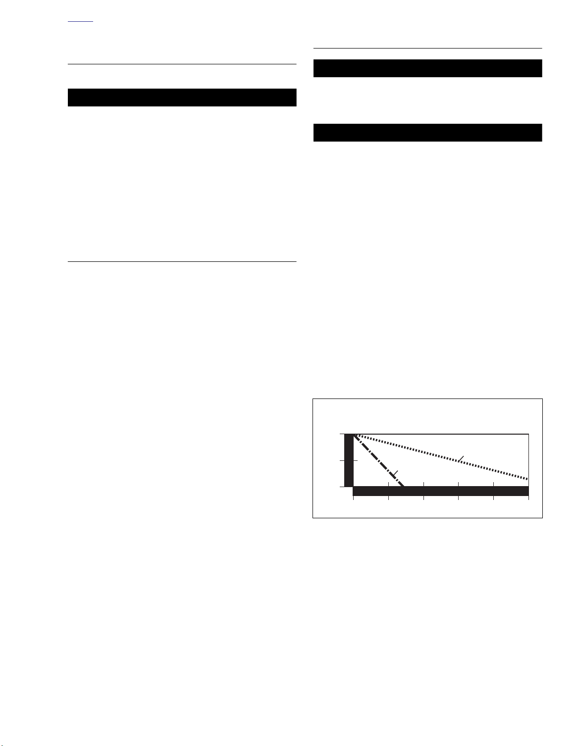
HOME
1WARNING1WARNING
CAUTION
f1732x8x
BATTERY DISCONNECTION AND
REMOVAL
1. Remove seat. See 2.41 SEAT.
1WARNING1WARNING
Always disconnect the negative batter y cable fi st. If the
positive cable should contact gr ound with the negative
cable installed, the resulting sparks may cause a batter y
explosion which could result in death or serious injury.
2. Unthread fastener and remo ve battery negative cable
(black) from battery negative (-) terminal.
3. Pull back terminal cover boot.
4. Unthread fastener and remo ve battery positive cable
(red) from battery positive (+) terminal.
5. Unhook strap and remove battery.
CLEANING AND INSPECTION
1. Battery top must be clean and dry. Dirt and electrolyte on
top of the batter y can cause batter y to self-discharge .
Clean battery top with a solution of baking soda (sodium
bicarbonate) and w ater (5 teaspoons baking soda per
quart or liter of water). When the solution stops bubbling,
rinse off the battery with clean water.
2. Clean cable connectors and batter y terminals using a
wire brush or sandpaper. Remove any oxidation.
3. Inspect the battery screws, clamps and cables for breakage, loose connections and corrosion. Clean clamps.
4. Check the batter y posts for melting or damage caused
by overtightening.
5. Inspect the batter y for discoloration, raised top or a
warped or distor ted case, which might indicate that the
battery has been frozen, overheated or overcharged.
6. Inspect the battery case for cracks or leaks.]
STORAGE
Always store batteries where they cannot be reac hed by
children. Contact with the batter y’s sulfuric acid could
result in death or serious injury.
The electrolyte in a disc harged battery will freez e if
exposed to freezing temperatures. Freezing ma y crack
the battery case and buckle battery plates.
If the motorcycle will not be oper ated for several months,
such as dur ing the winter season, remo ve the batter y from
the motorcycle and fully charge. See 7.11 BATTERY.
See Figure 1-2. Self-discharge is a normal condition and occurs
continuously at a rate that depends on the ambient temper ature
and the battery’s state of charge . Batteries discharge at a faster
rate at higher ambient temper atures. To reduce the self-discharge rate, store battery in a cool (not freezing), dry place.
Charge the batter y every month if stored at temper atures
below 60° F. (16° C). Charge the batter y more frequently if
stored in a warm area above 60° F. (16° C).
NOTE
The H-D Battery Tender Automatic Battery Charger (Part No.
99863-93TA) may be used to maintain battery charge for
extended periods of time without risk of overcharging or boiling.
When returning a battery to service after storage, fully charge
the battery. See 7.11 BATTERY.
Effect of Temperature on
Battery Self-Discharge Rate
100%
C
A
75%
50%
P
A
C
I
T
Y
0
at 105°F
MONTHS OF STAND
3691215
at 77
°
F
Figure 1-2. Battery Self-Discharge Rate
2004 Buell Lightning: Maintenance 1-9
Page 58

HOME
BATTERY INSTALLATION AND
CONNECTION
1. Place the fully charged batter y in the mounting position,
terminal side to the rear of motorcycle.
2. Hook rubber strap around body of battery.
CAUTION
Connect the cab les to the correct batter y terminals or
damage to the motorcycle electrical system will occur.
1WARNING1WARNING
Always connect the positive battery cable fi st. If the positive cable should contact ground with the negative cable
installed, the resulting sparks may cause a battery explosion which could result in death or serious injury.
CAUTION
Overtightening fasteners can damage battery terminals.
3. Insert fastener through batter y positive cable (red) into
threaded hole of battery positive (+) terminal and tighten
fastener to 72-96
4. Install terminal cover boot.
5. Insert fastener through battery negative cable (black) into
threaded hole of battery negative (-) terminal and tighten
fastener to 72-96
6. Apply a light coat of petroleum jelly or corrosion retardant
material to both battery terminals.
in-lbs
in-lbs
(8-11 Nm).
(8-11 Nm).
1WARNING1WARNING
After installing seat, pull upwar d on front of seat to be
sure it is locked in position. If seat is loose, it could shift
during vehicle operation and star tle the rider , causing
loss of contr ol which could result in death or serious
injury.
7. Install seat. See 2.41 SEAT.
1-10 2004 Buell Lightning: Maintenance
Page 59
HOME
8374
Operating Range
8352
ENGINE LUBRICATION SYSTEM 1.6
GENERAL
Check engine oil level (hot check) at every refueling stop.
Inspect oil lines and filter or leaks:
At 1000 mi (1600 km) initial ser vice and every 5000 mi
●
(8000 km) service interval.
Change engine oil and filter under
in warm or moderate temperatures:
●
At 1000 mi (1600 km) initial ser vice and every 2500 mi
(4000 km) interval thereafter.
●
When storing or removing the motorcycle for the season.
Change engine oil and filter under
in warm or moder ate temperatures (severe dust, temper atures above 80oF/27oC, extensive idling or speeds in e xcess
of 65 mph/105 km/h):
●
At 1000 mi (1600 km) initial ser vice and every 5000 mi
(8000 km) service interval thereafter.
●
When storing or removing the motorcycle for the season.
The colder the weather, the shorter the recommended oil
change interval. A vehicle used only for short runs in cold
weather must have the engine oil drained more frequently.
NOTE
normal service
severe service
conditions
conditions
CAUTION
Do not switch oil brands indiscriminately because some
oils interact c hemically when mixed. Use of inf erior oils
or non-detergent oils can damage the engine.
Ride motorcycle f or approximately 10 min utes to ensure the
oil is hot and the engine is at normal operating temperature.
1. The motorcycle m ust be on le vel ground, on the sidestand, with the engine off.
CHECKING ENGINE
OIL LEVEL
An accurate engine oil le vel reading can only be obtained
with the engine at nor mal operating temperature (hot check).
The engine will require a longer w arm up per iod in colder
temperatures.
For pre-ride inspection, simply v erify that there are no oil
leaks from the oil filter and oil lines p ior to oper ating the
motorcycle.
● Perform a hot chec k of the engine oil le vel at each fuel
stop.
Do not allow hot oil level to fall below lower mark on dipstick. To do so ma y result in equipment dama ge and/or
malfunction.
Do not o verfill oil tank. Overfilling oil tank m y result in
oil carryover to the air cleaner, equipment damage and/or
equipment malfunction.
CAUTION
CAUTION
Figure 1-3. Dipstick Location/Engine Oil Level
2. See Figure 1-3. Unscrew and remo ve dipstick from oil
tank/swingarm filler hol . Wipe dipstick clean.
3. Insert dipstick into oil tank filler hol , screwing dipstick in
completely. DO NOT OVER TIGHTEN.
NOTE
The area between the upper and lower registration marks is
the operating range.
4. See Figure 1-5. Unscrew and remo ve dipstick and note
oil level.
a. Oil level should be within the oper ating range
(between upper and lo wer registration marks) on
dipstick.
b. If oil level is below lower registration mark, add only
enough oil to bring oil level between lower and upper
registration marks.
2004 Buell Lightning: Maintenance 1-11
Page 60
HOME
CHANGING ENGINE OIL
AND FILTER
Ride motorcycle f or approximately 10 min utes to ensure the
oil is hot and the engine is at nor mal operating temperature.
Tu rn engine off.
NOTE
Secure rear wheel on lift or place scissor jack under jacking
point.
Draining Oil
1. See Figure 1-4. Place a suitab le container under the
drain plug.
8375
Changing Filter
1. Remove chin fairing See 2.34 CHIN FAIRING.
8418
Figure 1-6. Oil Filter
2. See Figure 1-6. Remove oil filter using pliers or belt typ
OIL FILTER WRENCH.
3. Clean filter gas et contact surface on crankcase. Surface
should be smooth and free of an y debris or old gask et
material.
4. Apply a thin film of clean engine oil to filter ga et.
5. Pour 4.0 ounces (0.12 liter) of clean engine oil into new fil
ter when changing oil (until filter is appr ximately 1/2 full).
6. Screw filter onto adapter until filter ga et touches crankcase surface. Rotate filter another 1/2-3/4 tu n by hand.
Figure 1-4. Oil Tank Drain Plug
2. Using a 5/8 in. wrench, remove drain plug from under oil
tank/swingarm. Wipe any accumulated debris from magnetic tip on drain plug.
8352
1WARNING1WARNING
Be sure no oil g ets on tires when changing oil and filte .
Traction will be adversely affected which may lead to loss
of control which could result in death or serious injury.
Figure 1-5. Dipstick Location
3. See Figure 1-5. Unscrew and remove dipstick from oil fil
hole on top of oil tank/swingarm.
1-12 2004 Buell Lightning: Maintenance
Page 61

HOME
Replacing Oil
1. Inspect drain plug o-ring for tears or damage. Replace if
required. Wipe any foreign material from drain plug.
2. Install drain plug and tighten to 29-31 ft-lbs (40-42 Nm).
3. Fill oil tank through filler (dipsti k) hole with recommended oil from Ta ble 1-4. Oil tank capacity with filte
change is appro ximately 2.5 quar ts (2.4 liters) and
includes the 4.0 ounces (0.12 liter) poured into the filte .
Always verify proper hot oil level on dipstick. Do not overfill
4. Inspect o-ring on dipstic k for rips or tears . Replace as
required.
NOTE
For ease of installation, apply a light film of clean engine oil to
the dipstick o-ring.
5. Install dipstick into oil tank/swingarm fill hol . Make sure
dipstick is installed completely . DO NO T OVER
TIGHTEN.
Table 1-4. Recommended Oil Grades
6. Remove left side oil cooler scoop . See 2.36 AIR
SCOOPS.
7. Inspect oil cooler fins or debris or damage. Blow out any
debris from fins with compressed air from the inside o
the cooler outward.
8. Wipe up any spilled oil on muffle .
9. Start engine. Verify that oil pressure signal light on instrument support turns off after a few seconds when engine
speed is 1000 RPM or above.
10. Check for oil leaks at oil filte , drain plug, hoses and oil
cooler.
11. Install chin spoiler. See 2.34 CHIN FAIRING.
12. Install air scoop 2.36 AIR SCOOPS.
13. Check (hot) oil le vel. See CHECKING ENGINE OIL
LEVEL.
HARLEY-DAVIDSON TYPE VISCOSITY
HARLEY-DAVIDSON
RATING
LOWEST AMBIENT TEMP
°F
COLD WEATHER
STARTS BELOW
50° F
H.D. Multi-Grade SAE 10W40 HD 360 Below 40° (4°C) Excellent
H.D. Multi-Grade SAE 20W50 HD 360 Above 40
H.D. Regular Heavy SAE 50 HD 360 Above 60
H.D. Extra Heavy SAE 60 HD 360 Above 80
°
(4°C) Good
°
(16°C) Poor
°
(27°C) Poor
2004 Buell Lightning: Maintenance 1-13
Page 62

HOME
BRAKE SYSTEM MAINTENANCE 1.7
GENERAL
Check brake fluid l vel and condition:
● When storing or removing the motorcycle for the season:
Replace D.O.T. 4 BRAKE FLUID.
● Every 2 years:
Front brake hand lever and rear brake foot pedal must have a
fi m feel when br akes are applied. If not, b leed system as
described.
Inspect front and rear brake lines and replace as required.
● Every 4 years:
Inspect caliper and master cylinder seals and replace as
required.
● Every 2 years:
If determining probable causes of poor brake operation, refer
to Ta bl e 1-5.
BLEEDING BRAKES
1WARNING1WARNING
D.O.T. 4 brake fluid can cause irritation of yes and skin,
and may be harmful if s wallowed. If a lar ge amount of
fluid is swallowed, induce vomiting by administering two
tablespoons of salt in a glass of warm water . Call a doctor. In case of contact with skin or eyes, flush with plent
of water. Get medical attention f or eyes. KEEP BRAKE
FLUID OUT OF THE REACH OF CHILDREN. Failure to
comply could result in death or serious injury.
1WARNING1WARNING
Never mix D.O.T. 4 with other brake fluids (su h as D.O.T.
5). Use only D.O.T. 4 brake fluid in moto cycles that specify D.O.T. 4 fluid on the rese voir cap. Mixing diff erent
types of fluid m y adversely affect braking ability and
lead to brake failure whic h could result in death or serious injury.
1WARNING1WARNING
Use only fresh, uncontaminated D .O.T. 4 fluid Cans of
fluid that ha ve been opened ma y have been contaminated by moisture in the air or dir t. Use of contaminated
brake fluid m y adversely affect braking ability and lead
to brake failure whic h could result in death or serious
injury
1WARNING1WARNING
Use only copper crush banjo washers (See Parts Catalog
for Part No.) with D.O.T. 4 brake fluid Earlier silver banjo
washers are not compatib le with D .O.T. 4 fluid and wil
not seal pr operly over time. Failure to compl y may
adversely affect braking ability and lead to brake failure
which could result in death or serious injury.
1WARNING1WARNING
Clean brake system components using denatured alcohol. Do not use mineral-base c leaning solvents, such as
gasoline or paint thinner . Use of mineral-base solvents
causes deterioration of rubber par ts that continues after
assembly. This may result in impr oper brake operation
which could result in death or serious injury.
1WARNING1WARNING
Always test motorcycle brakes at low speed after servicing or b leeding system. To prevent death or serious
injury, Buell recommends that all brake repair s be per formed by a Buell dealer or other qualified te hnician.
CAUTION
Cover molded-in-color surfaces and right handlebar
switches and use care when remo ving brake reser voir
cover and ad ding D.O.T. 4 brake fluid Spilling D .O.T. 4
brake fluid on molded-in-color surfaces will result in cos
metic damage. Spilling brake fluid on witches may render them inoperative.
1-14 2004 Buell Lightning: Maintenance
Page 63

HOME
Table 1-5. Brake Troubleshooting
CONDITION CHECK FOR REMEDY
Excessive lever/pedal travel or spongy
feel.
Brake fade Moisture in system. Bleed brake(s).
Chattering sound when brake is
applied.
Ineffective brake –
lever/pedal travels to limit.
Ineffective brake –
lever/pedal travel normal.
Brake pads drag on rotor –
will not retract.
Air in system.
Master cylinder low on fluid
Worn pads.
Worn D shape bushings
Loose mounting bolts.
Warped rotor.
Low fluid l vel.
Piston cup not functioning.
Distorted or glazed rotor.
Distorted, glazed or contaminated
brake pads.
Cup in master cylinder not uncovering
relief port.
Rear brake pedal linkage out of
adjustment.
Bleed brake(s).
Fill master cylinder with approved
brake fluid
Replace fluid in master cylinder with
approved brake fluid
Replace brake pads.
Replace rotor and bushings as set.
Tighten bolts.
Replace rotor and bushings as set.
Fill master cylinder with approved
brake fluid, and leed system.
Rebuild cylinder.
Replace rotor and bushings as set.
Replace pads.
Inspect master cylinder.
Adjust linkage.
2004 Buell Lightning: Maintenance 1-15
Page 64
HOME
Bleeding Front Brake
NOTE
Hydraulic brake fluid bladder-type pressure equipment can be
used to fill the brake master cylinder through the bleeder
valve if master cylinder reservoir cover is removed to prevent
pressurization.
1. See Figure 1-7. With motorcycle in upr ight position,
install end of plastic tubing o ver front caliper b leeder
valve; place other end in a clean container.
CAUTION
Cover molded-in-color surfaces and right handlebar
switches and use care when remo ving brake reser voir
cover and ad ding D.O.T. 4 brake fluid Spilling D .O.T. 4
brake fluid on molded-in-color surfaces will result in cos
metic damage. Spilling brake fluid on witches may render them inoperative.
2. Cover body surf aces, right handlebar s witches and
instrument panel to protect from spillage.
8346
Figure 1-7. Front Caliper Bleeder Valve
8359
3. See Figure 1-8. Remove two fasteners from front master
cylinder cover.
4. Add D.O.T. 4 BRAKE FLUID to master cylinder reser-
voir. Bring fluid l vel to within 1/8 in. (3.2 mm) of molded
boss inside front master cylinder.
NOTE
Do not reuse brake fluid.
5. Slowly depress and release hand le ver several times to
build up hydraulic pressure, then hold brake hand lever in
the depressed position.
6. While holding br ake hand le ver in the depressed position, open bleeder valve about 1/2-turn counterclockwise.
Brake fluid will f w from bleeder valve and through tubing into clean container. When brake lever has moved 1/2
to 3/4 of its full range of travel, close bleeder valve (clockwise). Allow brake lever to retur n slowly to its released
position.
7. Repeat steps 5-6 until all air bubbles are purged.
8. Tighten front caliper b leeder valve (metric) to 36-60 in-
lbs (4-7 Nm).
Figure 1-8. Front Master Cylinder Reservoir
9. Verify master cylinder fluid l vel as described in step 4.
10. Attach cover to front master cylinder reser voir and
tighten fastener to 9-13 in-lbs (1.0-1.5 Nm).
11. Remove cover from molded-in-color surfaces, right handlebar switches and instrument panel.
1-16 2004 Buell Lightning: Maintenance
Page 65
HOME
9956
Bleeding Rear Brake
NOTE
Hydraulic brake fluid bladder-type pressure equipment can be
used to fill the brake master cylinder through the bleeder
valve if master cylinder reservoir cover is removed to prevent
pressurization.
8348
Figure 1-10. Rear Master Cylinder Reservoir
2. See Figure 1-10. Remove cap and gasket from rear master cylinder reservoir.
3. Add D.O.T. 4 BRAKE FLUID to master cylinder reservoir
with motorcycle upr ight (not on sidestand). Bring flui
level between upper and lower marks on reservoir.
Figure 1-9. Rear Caliper Bleeder Valve
1. See Figure 1-9. With motorcycle in upr ight position,
install end of plastic tubing o ver rear caliper b leeder
valve; place other end in a clean container.
CAUTION
Cover molded-in-color surfaces and use care when
removing brake reser voir cover and ad ding D.O.T. 4
brake fluid Spilling D .O.T. 4 brake fluid on molded-in
color surfaces will result in cosmetic damage.
NOTE
Do not reuse brake fluid.
4. Slowly depress and release brake pedal several times to
build up hydraulic pressure, then hold brake pedal in the
depressed position.
5. While holding br ake pedal in the depressed position,
open bleeder valve about 1/2-tur n counterclockwise.
Brake fluid will f w from bleeder valve and through tubing into clean container. When brake pedal has moved
1/2 to 3/4 of its full r ange of tr avel, close b leeder valve
(clockwise). Allow brake pedal to retur n slowly to its
released position.
6. Repeat steps 5-6 until all air bubbles are purged.
7. Tighten rear caliper b leeder valves (metric) to 36-60 in-
lbs (4-7 Nm).
8. Verify master cylinder fluid l vel as described in step 3.
9. Install cover on master cylinder reservoir and tighten cap
securely.
2004 Buell Lightning: Maintenance 1-17
Page 66
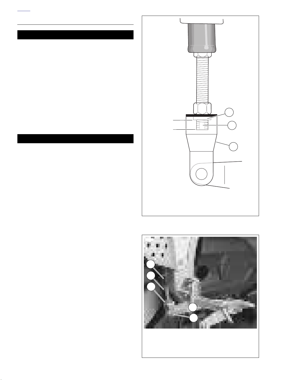
HOME
BRAKE PEDAL ADJUSTMENT
1WARNING1WARNING
After completing repair s or bleeding the system, always
test motorcycle brakes at lo w speed. If brakes are not
operating properly or braking efficien y is poor , testing
at high speeds could result in death or serious injur y.
(289)
Before every ride, check rear brake pedal operation.
NOTES
● See Figure 1-11. On the very end of the threaded brake
rod, are two flat sides (2). To ensure proper thread
engagement with the clevis (3), the flat sides must
extend below the extruded nut (1) in the clevis by at least
one full thread. This is the minimum rod engagement.
● Also, there should be a minimum of 0.030 in. (0.8 mm)
between brake rod end and brake pedal.
1WARNING1WARNING
Threaded rod should not be adjusted to the point of contacting brake pedal. Improper adjustment could result in
death or serious injury.
b0615x1x
Minimum
Engagement
1
2
3
1. See Figure 1-12. Inspect for minimum and maxim um
brake rod engagement in br ake clevis (4). Adjust as
required.
2. Adjust brake pedal.
a. See Figure 1-12. Loosen locknut (3) while holding
rod adjuster (2). Move locknut away from top surface
of clevis (4).
b. Tu rn rod adjuster to set pedal height.
c. Return locknut (3) to fit flush against top su ace of
clevis and tighten to 130-173.5 in-lbs (14.7-19.6
Nm).
NOTE
Brake pedal has no free play adjustment.
1. Extruded nut
2. Flat sides (on the end of the threaded brake rod)
3. Clevis
Figure 1-11. Critical Measurements with Typical
Brake Pedal
8349
1
2
3
4
1-18 2004 Buell Lightning: Maintenance
5
1. Bottom of master cylinder
2. Rod adjuster
3. Locknut
4. Clevis
5. Clevis pin
Figure 1-12. Rear Brake Pedal Pushrod Adjustment
Page 67
HOME
7082
1. Friction material
2. Wear groove
3. Backing material
1
2
3
8347
8347
BRAKE PAD THICKNESS
1WARNING1WARNING
Always replace brake pads in complete sets f or correct
brake operation. Never replace just one brake pad. Failure to install brake pads as a set could result in death or
serious injury. (111)
See Figure 1-13. Inspect brake pads for damage or excessive
wear. Replace both pads as a set if fr iction material of either
pad is w orn to 0.040 in. (1.0 mm) or less . If this amount of
wear occurs, wear grooves will disappear from fr iction material surface.
BRAKE ROTOR THICKNESS
1WARNING1WARNING
Do not allow brake fluid bearing grease, lubricants, etc.
to contact brake r otor when ser vicing motorcycle or
reduced braking ability will occur , which could result in
death or serious injury.
See Figure 1-14. Check brake rotors for minimum thickness:
● At the 1000 mile (1600 km) service interval.
● At every 5000 mile (8000 km) service interval thereafter.
● At every scheduled service interval:
1. Measure rotor thickness. Replace rotor if minimum thickness is less than 0.18 in. (4.5 mm). Replace drive bushings, fasteners, washers and spr ings whenever rotor is
replaced.
2. Check rotor surface. Replace if warped or badly scored.
See 2.5 FRONT WHEEL or 2.6 REAR WHEEL for proce-
dure.
Figure 1-13. Brake Pad Thickness
Figure 1-14. Front Brake Rotor
2004 Buell Lightning: Maintenance 1-19
Page 68
HOME
BRAKE PAD REPLACEMENT
Front Pad Removal
1. See Figure 1-15. Loosen pin hanger (2) b ut do not
remove.
2. Rotate wheels so that caliper is centered betw een rotor
mounting fasteners (1).
3. Remove lower caliper mounting fastener (4) that secures
caliper to fork lower.
4. Loosen but do not remo ve upper caliper mounting f astener (3) that secures caliper to fork lower.
5. Remove pin hanger (2).
6. Rotate caliper counterclockwise to allow access to outer
pad.
7. Remove outer pad from right side.
8. Remove inner pad from left side b y pulling rearw ard,
rotating pad 90 degrees and pulling through wheel opening.
Front Pad Installation
1. Push pistons in with suitab le tool such as a clean paint
scraper until fully seated in bores. Be careful not to damage rotor.
2. Install new inner pad from left side of motorcycle.
3. Install new outer pad from right side of motorcycle.
4. See Figure 1-15. Install pin (2) making sure it engages
hole on both pads and spring clip.
5. Rotate caliper clockwise to align mounting fastener hole.
6. See Figure 1-15. Install lower caliper mounting
fastener (4).
7. Tighten both caliper mounting fasteners (3, 4) to 35-37 ftlbs (48-50 Nm).
8. Tighten pin (2) to 11-14 ft-lbs (15-19 Nm).
NOTE
Avoid making hard stops for the first 100 miles (160 km) to
allow new brake pads to “wear in” properly with the rotor.
8346
1
2
1. Rotor mounting fastener (6)
2. Front caliper pin hanger
3. Upper caliper mounting fastener
4. Lower caliper mounting fastener
Figure 1-15. Front Brake Caliper
3
4
1-20 2004 Buell Lightning: Maintenance
Page 69
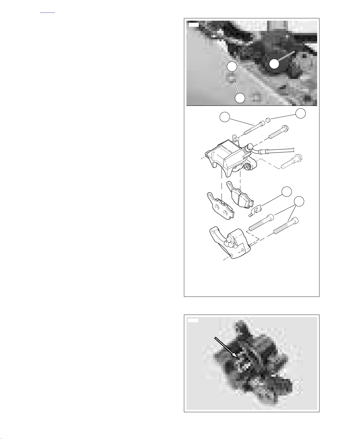
8348
1. Rear caliper mounting fasteners
2. Retainer,
3. Rear caliper pin plug
4. Rear caliper hanger pin
3
3
4
1
2
1
2
b1143x1x
6487
HOME
Rear Pad Removal
1. See Figure 1-16. Remove rear caliper pin plug (3) and
loosen pin (4).
2. Remove fastener securing p-clamp, wire form and brake
line assembly to swingarm.
3. Remove two mounting fasteners (1) securing brake caliper and carrier assembly to swingarm.
4. Lift caliper and carrier assembly up and off of rotor.
5. Remove hanger pin (4).
6. Remove inner and outer pads , being careful not to dislodge pad spring.
Rear Pad Installation
1. See Figure 1-16. Check that retainer (2) is present.
2. See Figure 1-17. Check that pad spr ing is present.
Should pad spring become dislodged, install with widest
area of spring towards piston side of caliper.
3. Push piston in with suitab le tool such as a clean paint
scraper until fully seated in bore.
4. Install new inner and outer brake pads
5. See Figure 1-16. Install hanger pin (4) making sure pin
engages hole on both pads.
6. Install brake caliper and carrier assembly over rotor.
7. Install two mounting fasteners (1) through swingarm into
carrier and tighten to 35-37 ft-lbs (48-50 Nm).
8. Apply LOCKTITE 272 and tighten hanger pin to 11-14 ftlbs (14.9-18.9 Nm).
9. Install pin plug (3). Tighten plug to 18-25 in-lbs (2-
3 Nm).
10. Install fastener securing p-clamp, wire f orm and br ake
line assembly to s wingarm and tighten to 36-60 in-lbs
(4.1-6.8 Nm).
Avoid making hard stops for the first 100 miles (160 km) to
allow new brake pads to “wear in” properly with the rotor.
NOTE
Figure 1-16. Rear Brake Caliper
Figure 1-17. Rear Brake Pad Spring
2004 Buell Lightning: Maintenance 1-21
Page 70
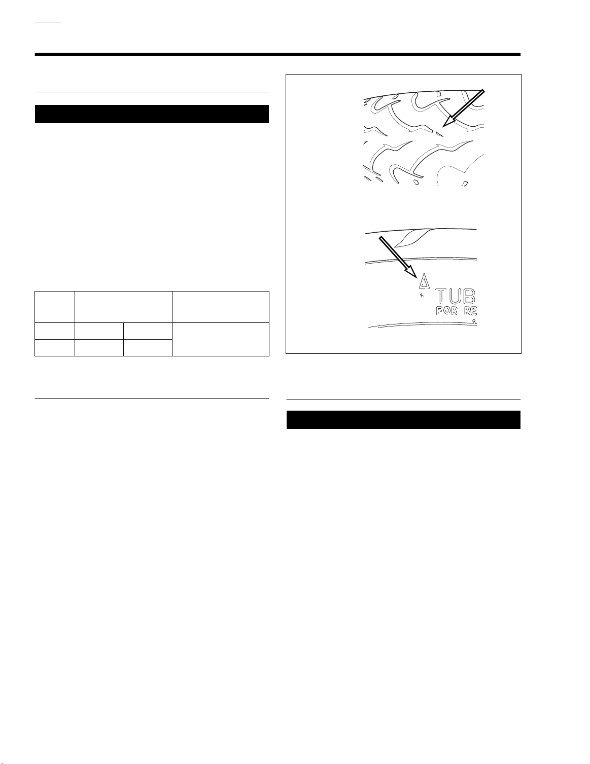
HOME
TIRES AND WHEELS 1.8
TIRE INFLATION
1WARNING1WARNING
Do not inflate a y tire beyond its maximum inflation pres
sure as specified on tire sid wall. Overinflation m y
cause tire to suddenly deflate whi h could result in death
or serious injury.
Check tire pressure and tread:
● Before every ride.
Check for proper front and rear tire pressures when tires are
cold. Compare pressure against Tab le 1-6.
Table 1-6. Tire Pressures
TIRE
Front 36 PSI 248 kPa
Rear 38 PSI 262 kPa
PRESSURE FOR
SOLO RIDING
PRESSURE AT
GVWR
Same as solo riding
o0248xox
Wear indicator bar
o0247xox
Wear indicator sidewall arrow
Figure 1-18. Tire Wear Indicator
TIRE REPLACEMENT
See Figure 1-18. Treadwear indicator bars will appear on tire
tread surfaces when 1/32 in. (0.8 mm) or less of tire tread
remains. Arrows on tire side walls pinpoint location of w ear
bar indicators. Always remove tires from ser vice before they
reach the treadw ear indicator bars (1/32 in. [0.8 mm] tread
pattern depth remaining).
New tires are needed if any of the following conditions exist.
1. Tire wear indicator bars become visible on the tread surfaces.
2. Tire cords or fabric become visible through cracked sidewalls, snags or deep cuts.
3. A bump, bulge or split in the tire.
4. Puncture, cut or other damage to the tire that cannot be
repaired.
WHEEL BEARINGS
1WARNING1WARNING
Never use compressed air to “spin-dry” bearings. Very
high bearing speeds can dama ge unlubricated bearings.
Spinning bearings with compressed air can also cause a
bearing to fly apa t, which could result in death or serious injury.
Check front and rear wheel bearings for wear:
● Every time a wheel is removed.
● When storing or removing the motorcycle for the season.
Check wheel bearings for wear and corrosion. Excessive play
or roughness indicates w orn bearings. Replace bear ings in
sets only.
1-22 2004 Buell Lightning: Maintenance
Page 71
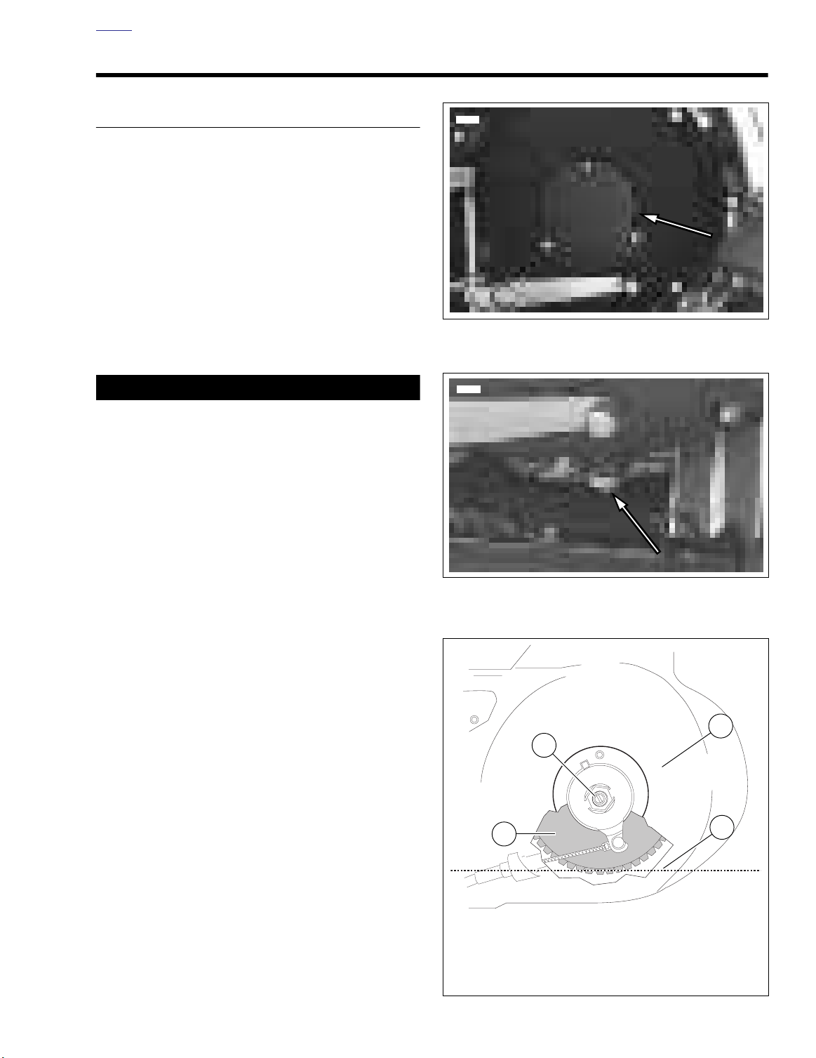
HOME
8356
8376
b1144x1x
1. Clutch diaphragm spring
2. Clutch adjusting screw
3. Primary cover
4. Correct chaincase lubricant level
1
2
3
4
CLUTCH 1.9
TRANSMISSION FLUID
Tr ansmission fluid capacity is appr ximately 1.0 quart
(0.95 liter). For best results, drain fluid while hot
1. On level surface, stand v ehicle upright (not leaning on
sidestand) to pre vent chaincase lubr icant from dr aining
out of clutch cover opening when refilled
2. See Figure 1-20. Position a suitab le container under
drain plug. Remove plug and drain fluid
3. Wipe any foreign material from the magnetic dr ain plug
and apply Loctite 592 Thread Sealant. Reinstall plug and
tighten to 11-15 ft-lbs (14.9-20.3 Nm).
4. Remove three fasteners and washers from clutch inspection cover. Remove clutch inspection co ver with gask et
from primary cover.
CAUTION
Do not o verfill the transmission with fluid Overfillin
may cause rough clutch engagement and incomplete disengagement, clutch drag and/or difficulty finding neutr
at engine idle.
Figure 1-19. Clutch Inspection Cover
5. See Figure 1-21. Add SPORT-TRANS FLUID (Part No.
99896-88 quart size; Part No. 99895-88 gallon siz e) as
required until fluid l vel (3) is e ven with bottom of clutch
diaphragm spring (2).
NOTE
Each time the clutch inspection cover is removed the gasket
must be replaced.
6. Install new clutch cover gasket.
7. See Figure 1-19. Install clutch inspection co ver tighten-
ing three f asteners and w ashers to 84-108 in-lbs (10-
12 Nm).
8. Clean up any fluid that m y have spilled on muffle .
Figure 1-20. Primary Drain Plug
Figure 1-21. Fluid Level
2004 Buell Lightning: Maintenance 1-23
Page 72
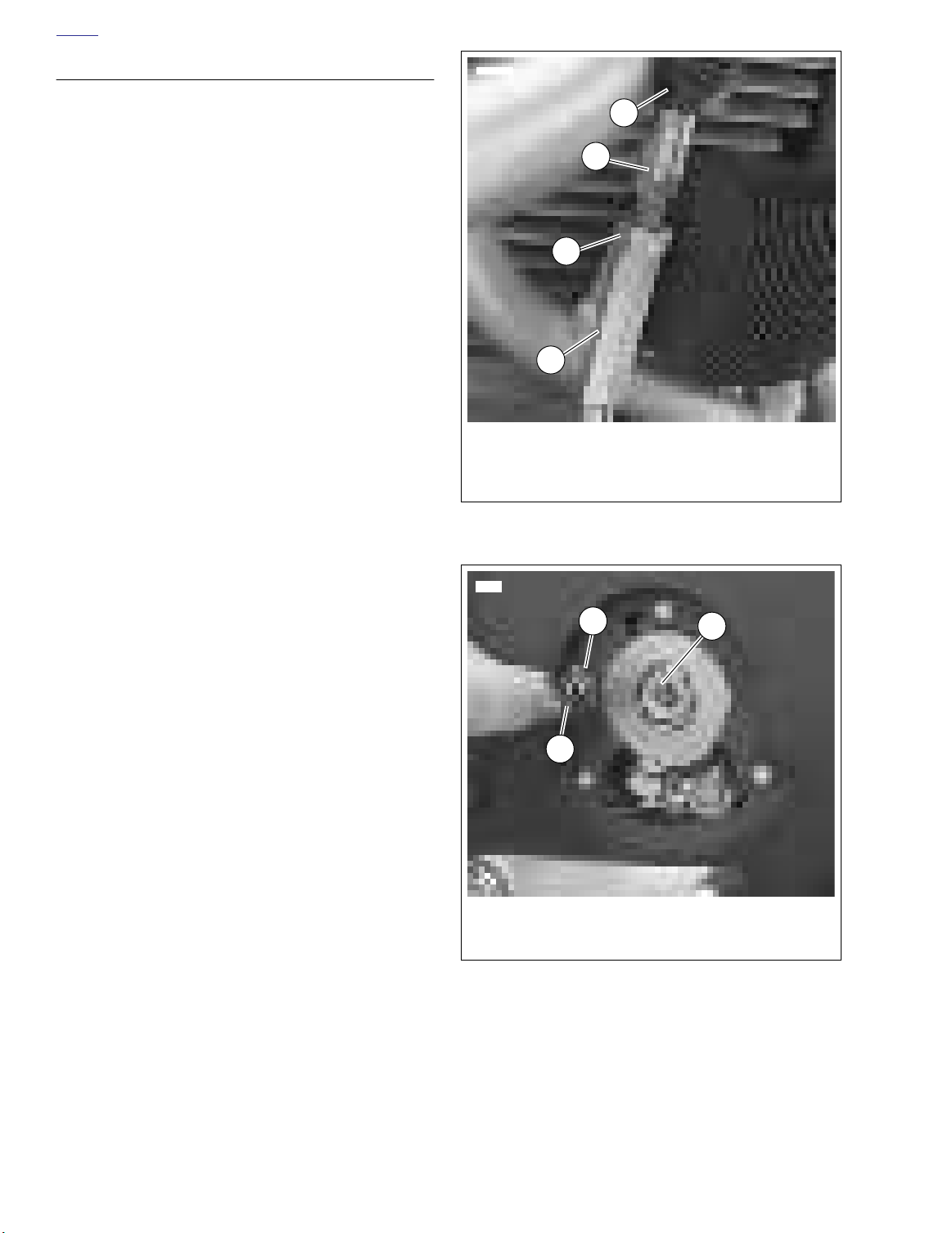
HOME
ADJUSTMENT
If clutch slips under load or dr ags when released, first che k
control cable adjustment. If cable adjustment is within specifi
cations, adjust clutch mechanism as described below.
When necessary, lubricate cable with LUBIT -8 TUFOIL
CHAIN AND CABLE LUBE (Part No. HD-94968-85TV).
1. Raise rear wheel off floor using REAR WHEEL SUPPORT STAND (Part No. B-41174).
2. See Figure 1-22. Slide rubber boot (1) upward to expose
adjuster mechanism. Loosen jam n ut (3) from adjuster
(4). Turn adjuster to shorten cable housing until there is a
large amount of free play at clutch hand lever.
3. See Figure 1-19. Remove three f asteners and washers
from clutch inspection co ver. Remove clutch inspection
cover and gasket from primary cover.
4. See Figure 1-23. Remove spring (1) and loc kplate (2).
Using a flat tip scr wdriver, turn adjusting scre w (3)
counterclockwise until it lightly bottoms.
5. Turn adjusting screw clockwise 1/4-1/2 turn. Install loc kplate and spring on adjusting scre w flat . If hex on lockplate does not align with recess in outer r amp, rotate
adjusting screw clockwise until it aligns.
NOTE
Spring installs on outboard side of hex lockplate.
®
1. Rubber boot
2. Cable end
3. Jam nut
4. Adjuster
8411
1
2
3
4
Figure 1-22. Clutch Cable Adjuster Mechanism
8405
2
1
1. Diaphragm spring
2. Lockplate
3. Adjusting screw
Figure 1-23. Clutch Adjustment
3
1-24 2004 Buell Lightning: Maintenance
Page 73
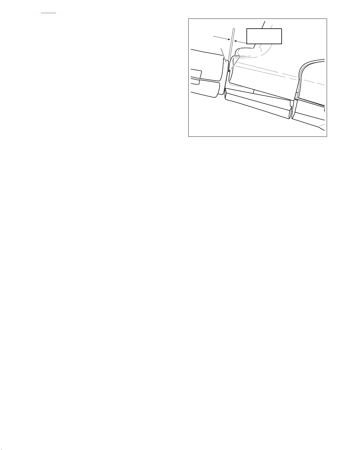
HOME
b0289x6x
Bracket
Ferrule
1/16-1/8 in.
(1.6-3.2 mm)
6. Squeeze clutch hand lever to maximum limit three times.
This sets the ball and r amp mechanism. Pull outer cable
conduit and at the same time adjust cab le adjuster to
provide 1/16-1/8 in. (1.6-3.2 mm) free play at clutch hand
lever. Adjust as follows:
a. See Figure 1-24. Pull ferrule (end of cable housing)
away from bracket. Gap between ferrule and bracket
should be 1/16-1/8 in. (1.6-3.2 mm).
b. See Figure 1-22. Set free pla y by turning adjuster
(4).
c. Tighten jam nut (3) against adjuster (4).
d. Slide boot (1) over cable adjuster mechanism.
7. Change or add transmission fluid if necessa y.
NOTE
Each time the clutch inspection cover is removed the gasket
must be replaced.
8. See Figure 1-19. Install clutch inspection cover and new
gasket using three fasteners and washers and tighten to
84-108 in-lbs (10-12 Nm).
9. Check clutch cable free play. See Step 6 above.
Figure 1-24. Adjusting Clutch Free Play
2004 Buell Lightning: Maintenance 1-25
Page 74
HOME
DRIVE BELT 1.10
GENERAL
The drive belt tension on a ne w belt will be considerably tight
and will loosen after appro ximately 1000 miles (1600 km).
The drive belt tension is automatically maintained by the idler
pulley. Axle alignment is not adjustable.
Replace drive belt and idler pulley assembly:
● At every 25,000 mile (40,000 km) service interval.
INSPECTION
Rear Sprocket
NOTE
If chrome chips or gouges to rear sprocket are large enough
to be harmful, they will leave a pattern on the belt face.
1. Inspect each tooth of rear sprocket for:
a. Major tooth damage.
b. Large chrome chips with sharp edges.
c. Gouges caused by hard objects.
d. Excessive loss of chrome plating (see Step 2).
2. To check if chrome plating has w orn off, drag a scribe or
sharp knife point across the bottom of a g roove (2)
(between two teeth) with medium pressure.
a. If scribe or knife point slides across g roove without
digging in or lea ving a visible mark, chrome plating
is still good.
b. If scribe or knif e point digs in and lea ves a visib le
mark, it is cutting the bare alumin um. A knife point
will not penetrate the chrome plating.
3. Replace rear sproc ket if major tooth damage or loss of
chrome exists.
Drive Belt
Refer toTa ble 1-7. Inspect drive belt for:
● Cuts or unusual wear patterns on both sides of belt.
● Outside edge be velling (8). Some bevelling is common,
but it indicates that sprockets are misaligned.
● Outside surface for signs of stone puncture (7). If cracks/
damage exists near edge of belt, replace belt immediately. Damage to center of belt will require belt replacement eventually, but when cracks extend to edge of belt,
belt failure is imminent.
● Inside (toothed portion) of belt for exposed tensile cords
(normally covered by nylon layer and polyethylene layer).
This condition will result in belt failure and indicates worn
transmission sprocket teeth. Replace belt and tr ansmission sprocket.
● Signs of puncture or cr acking at the base of the belt
teeth. Replace belt if either condition exists.
Idler Pulley
See Figure 1-25. Inspect idler pulley for signs of uneven wear.
Excessive lateral side play of 0.020 in. (0.5 mm) or roughness
indicates worn bearings. Replace idler pulley as an assembly.
See 6.6 DRIVE BELT SYSTEM.
10124
1-26 2004 Buell Lightning: Maintenance
Figure 1-25. Checking Lateral Side Play on Idler Pulley
with a Dial Indicator
CLEANING
Keep dirt, grease, oil, and debr is off the belt, idler pulle y and
sprockets. Clean the dr ive belt with a mild soap and w ater
spray solution as required. Dry thoroughly. Do not immerse
belt in solution.
Page 75
HOME
Table 1-7. Potential Limits to Belt Drive Service Life
CONDITION ROOT CAUSE REQUIRED ACTION
Misalignment or bent drive structure Check structure (bad bearing, bent members, etc.)
Bent or rough flang Repair flange/replace spro ket
Damage due to handling (pry on, etc.) Follow proper handling/installation procedure
Inspect/replace belt
Inspect for damaged or missing guards
Check structure (bad bearing, bent members, etc.)
Inspect for loose/missing fasteners
Inspect for damaged or missing guards
Replace idler assembly
Inspect for loose/missing fasteners
Check structure (bad bearing, bent members, etc.)
Inspect for loose/missing fasteners
Inspect for damaged or missing guards
Clean and protect drive
Inspect for damaged or missing guards
Eliminate or control exposure
Inspect for damaged or missing guards
Clean and protect drive
Inspect for damaged or missing guards
Eliminate or control exposure
Clean and protect drive
Eliminate or control exposure
Clean and protect drive
Inspect/replace sprocket
Continue to run but monitor condition frequently
Inspect/replace sprocket
Inspect/replace belt
Excessive Edge Wear
(mistracking)
Excessive tooth wear
Apparent belt stretch
Cracks in back of belt
Debris damage to edge of belt
Belt hitting obstruction
Bent or loose idler bracket
Broken or loose guards
Rough or damaged sprocket Inspect/replace sprocket
Worn sprocket Inspect/replace sprocket
Debris in sprocket
Abrasive environment
Worn sprocket Inspect/replace sprocket
Debris in sprocket
Idler bearing failure Replace idler assembly
Aggressive riding/hard use Riding practice/operator choice
Exposure to oils, solvents, harsh chemicals
Idler/bearing binding Replace idler assembly
Exposure to oils, solvents, harsh chemicals
Cut by sharp debris (not at belt edge)
Cut by sharp debris at belt edge
2004 Buell Lightning: Maintenance 1-27
Page 76
HOME
Table 1-7. Potential Limits to Belt Drive Service Life
CONDITION ROOT CAUSE REQUIRED ACTION
To oth shear/cracks
Belt breakage
Excessive drive noise
Excessive load/shock load
Worn sprocket Inspect/replace sprocket
Debris damage
Excessive load/Shock load
Damage due to handling (pry-on, etc.) Follow proper handling/installation procedure
Debris in sprocket or belt
Worn/damaged sprocket Inspect/replace sprocket
Damaged flang Repair flange/replace spro ket
Damaged idler
Damaged belt
Debris stuck in belt
Debris stuck in sprocket
Inspect/replace belt
Riding practice/operator choice
Inspect/replace sprocket
Clean and protect drive
Inspect/replace belt
Continue to run but monitor condition frequently
Inspect for damaged or missing guards
Inspect/replace belt
Riding practice/operator choice
Inspect/replace sprocket
Clean and protect drive
Inspect/replace belt
Check structure (bad bearing, bent members, etc.)
Replace idler assembly
Follow proper handling/installation procedure
Inspect/replace belt
Inspect/replace sprocket
Clean and protect drive
Inspect/replace belt
Inspect/replace sprocket
Follow proper handling/installation procedure
Inspect/replace belt
1-28 2004 Buell Lightning: Maintenance
Page 77
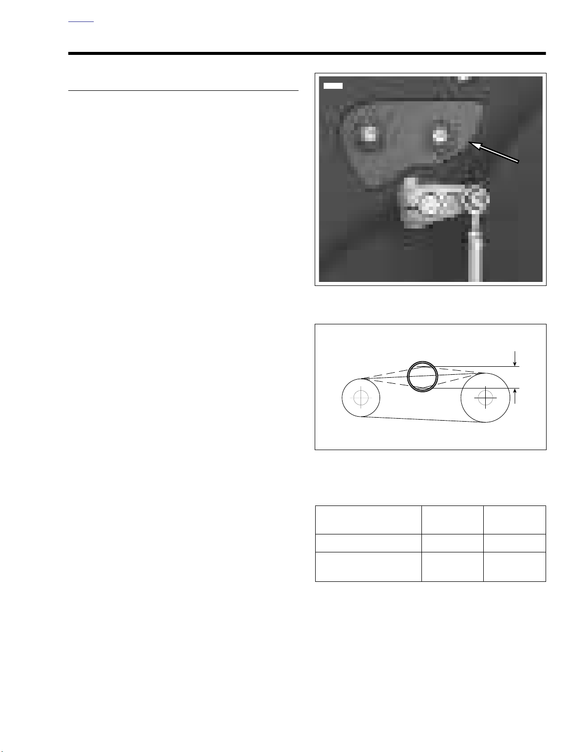
HOME
8356
b0085a6x
PRIMARY CHAIN 1.11
INSPECTION
See Figure 1-26. Measure primary chain tension through the
inspection cover opening. Adjust primary chains not meeting
vertical free play specification .
1. See Figure 1-26. Remove two fasteners with captiv e
washers and primary chain inspection cover with gasket
from primary cover.
2. See Figure 1-27. Check primary chain tension b y measuring vertical free play.
a. Measure vertical free play through chain inspection
cover opening.
b. Rotate engine to mo ve primary chain to a diff erent
position on sprockets.
c. Measure vertical free pla y several times, each time
with primary chain moved so that the measurement
is taken with sprockets rotated to the tightest chain
position.
3. The tightest measurement taken in Step 2 must be within
the specifications listed in Ta bl e 1-8. If necessary, adjust
as described under 1.11 PRIMARY CHAIN in ADJUST-
MENT.
Figure 1-26. Primary Chain Inspection Cover
NOTE
The initial primary chain vertical free play specification used
at the assembly plant is 1/4-1/2 in. (6.4-12.7 mm) with a cold
engine. The 1/4 in. (6.4 mm) minimum is only allowed at the
absolute tightest point in the drive, as measured with specialized factory equipment. If a chain has less than 1/4 in.
(6.4 mm) vertical free play (with a cold engine), adjust free
play to the “field” specification of 3/8-1/2 in. (9.5-12.7 mm).
The looser specification will avoid ov ertightening, which might
otherwise occur during adjustment using “non-factory” equipment and methods.
4. See Figure 1-26. Install primary chain inspection co ver
and
new
gasket to pr imary cover using tw o fasteners
with captive washers. Tighten fasteners to 40-60
(5-7 Nm).
in-lbs
Figure 1-27. Measuring Primary Chain Free Play
Table 1-8. Primary Chain Free Play
ENGINE
TEMPERATURE
Cold 3/8-1/2 9.5-12.7
Hot (normal running
temperature)
in. mm
1/4-3/8 6.4-9.5
2004 Buell Lightning: Maintenance 1-29
Page 78
HOME
ADJUSTMENT
NOTE
If vertical free play cannot be set within the limits specified,
then primary chain and/or chain adjuster are worn beyond
adjustment limits. Replace parts as necessary. See 6.5 PRI-
MARY CHAIN.
1. See Figure 1-28. Loosen locknut (1).
2. Turn adjusting fastener (2):
a. Clockwise (inward) to reduce free play.
b. Counterclockwise (outward) to increase free play.
3. Tighten locknut (1) to 20-25 ft-lbs (27-34 Nm).
8403
2
1. Locknut
2. Adjusting Fastener
Figure 1-28. Chain Tension Adjusting Fastener
1
1-30 2004 Buell Lightning: Maintenance
Page 79
HOME
SUSPENSION DAMPING ADJUSTMENTS 1.12
GENERAL
1WARNING1WARNING
Before evaluating and adjusting suspension settings,
check the motorcycle’s tires. Tires must be in good condition and pr operly inflated Failure to c heck the tires
could result in death or serious injury.
ments. Adjusting more than one or tw o clicks at a time ma y
cause you to skip the best adjustment. Test ride after each
adjustment. When an adjustment makes no difference, return
to the previous adjustment and try a different approach.
Table 1-9. Recommended Suspension Settings for Rider Weight (XB9S, XB12S)
RIDER AND CARGO
WEIGHT
PRELOAD
LB. KG
Less than 130 59 7 2 1.75 1 2.50 2
130-150 59-68 6.5 1.75 1.75 2 2.25 1.75
# OF
LINES
FRONT FORK REAR SHOCK
*COMPRESSION *REBOUND
If both preload adjustments are correct, and y ou have the
rebound and compression damping set at the f actory recommended points, the motorcycle should handle and r ide properly. If y ou wish to fine tune these settings th y can be
changed according to the following procedures.
NOTE
Evaluating and changing the rebound and compression
damping is a very subjective process. Many variables affect
motorcycle handling under different circumstances. Approach
all changes carefully and consult Table 1-9.
PRELOAD
POSITION
*COMPRESSION *REBOUND
150-170 68-77 6 1.50 1.625 3 2 1.50
170-190 77-86 5.5 1.50 1.50 4 1.75 1.50
190-210 86-95 5 1.25 1.50 5 1.50 1.25
210-230 95-104 4.5 1.25 1.50 6 1.25 1
230-GVWR 104-GVWR 4 1 1.25 7 1.25 1
* Note all compression and rebound settings are number of turns out from maximum.
Table 1-10. Recommended Suspension Settings For Rider Weight (XB9SL)
RIDER AND CARGO WEIGHT FRONT FORK REAR SHOCK
PRELOAD
LB. KG
Less than 150 68 6 1.75 1.75 1 3 1.5
150-170 68-77 5.5 1.75 1.5 2 2.5 1.25
170-190 77-86 5 1.5 1.5 3 2.25 1.25
190-210 86-95 4.5 1.5 1.25 4 2 1
210-230 95-104 4 1.25 1.25 5 1.75 1
# OF
LINES
*COMPRESSION *REBOUND
PRELOAD
POSITION
*COMPRESSION *REBOUND
230-250 104-113 3.5 1.25 1 6 1.5 0.75
250-GVWR 113-GVWR 3 1 1 7 1.25 0.75
* Note all compression and rebound settings are number of turns out from maximum.
2004 Buell Lightning: Maintenance 1-31
Page 80
HOME
SUSPENSION ADJUSTMENTS
1WARNING1WARNING
Always adjust each fork leg to the same settings. Uneven
adjustment between left and right f orks may lead to a
loss of contr ol which could result in death or serious
injury.
NOTE
All “turn settings” in Table 1-9. and Table 1-10. are “turns out
from maximum”. That is, first gently turn adjustment screws
fully clockwise (until they stop), then turn adjustment screws
counterclockwise the amount specified.
The recommended rebound and compression damping settings for various road and riding conditions are given in Table
1-10. and Table 1-10.
Setting Front Fork Preload
1. Check number of lines (3) to be showing for your load
condition. Refer to Table 1-9. or Table 1-10.
2. See Figure 1-29. Adjust preload by turning the adjuster
nut (2) with a wrench.
Setting Front Fork Rebound Damping
1. See Figure 1-29. Using a screwdriver, turn the slotted dial
(1) clockwise until it stops. This is the maximum rebound
damping setting.
2. Then turn the dial counterclockwise the recommended
amount specified in Table 1-9. or Table 1-10.
9957
1
2
3
1. Rebound adjuster screw
2. Preload adjuster nut
3. Four lines visible (factory setting)
Figure 1-29. Front Fork Preload And Rebound Adjuster
8361
Setting Front Fork Compression Damping
1. See Figure 1-30. Using a screwdriver, turn the slotted dial
clockwise until it stops. This is the maximum compression
damping setting.
2. Then turn the dial counterclockwise the recommended
amount specified in Table 1-9. or Table 1-10.
Figure 1-30. Front Fork Compression Damping Adjuster
1-32 2004 Buell Lightning: Maintenance
Page 81
HOME
8388
Maximum preload adjustment (ramp number 7)
Minimum preload adjustment (ramp number 1)
b0954x1x
8416
Setting Rear Shock Preload
The factory setting is ramp number 2 position (ramp number 7
position being the tallest ramp and maximum preload). For
recommended spring preload refer to Table 1-9. or Table 1-
10.
1. Remove seat. See 2.41 SEAT.
2. See Figure 1-31. Change the spring preload by turning
the preload adjuster at the upper par t of the shoc k with
the SHOCK SP ANNER WRENCH (HD-94700-52C) or
the wrench included in the tool kit.
a. Turn adjuster to setting specified in Table 1-9. or
Table 1-10. Rotate adjuster cloc kwise to increase
preload.
b. Rotate adjuster countercloc kwise to decrease pre-
load.
1WARNING1WARNING
After installing seat, pull upwar d on front of seat to be
sure it is locked in position. If seat is loose, it could shift
during vehicle operation and star tle the rider , causing
loss of contr ol which could result in death or serious
injury.
3. Install seat. See 2.41 SEAT.
Figure 1-31. Rear Shock Preload Adjuster
Setting Rear Shock Rebound Damping
1. See Figure 1-32. Using a screwdriver, turn the slotted dial
clockwise until it stops. This is the maximum rebound
damping setting.
2. Then turn the dial countercloc kwise the recommended
amount specified in Table 1-9. or Table 1-10.
Figure 1-32. Rear Shock Rebound Adjustment
2004 Buell Lightning: Maintenance 1-33
Page 82
HOME
Setting Rear Shock Compression
Damping
1. Remove seat. See 2.41 SEAT.
2. See Figure 1-33. Using a scre wdriver, turn the slotted
dial clockwise until it stops . This is the maxim um compression damping setting.
3. Then turn the dial counterclockwise the recommended
amount specified in Table 1-9. or Table 1-10.
1WARNING1WARNING
After installing seat, pull upwar d on front of seat to be
sure it is locked in position. If seat is loose, it could shift
during vehicle operation and star tle the rider , causing
loss of contr ol which could result in death or serious
injury.
4. Install seat.
8976a
Figure 1-33. Rear Shock Compression Adjustment
1-34 2004 Buell Lightning: Maintenance
Page 83
HOME
8421
STEERING HEAD BEARINGS 1.13
GENERAL
The steering head bearings are sealed, angular contact bearings and do not require additional lubrication.
Check steering head bearing resistance:
At every 5000 mile (8000 km) service interval.
●
●
When storing or removing the motorcycle for the season.
INSPECTION
NOTES
Check that throttle cables do not bind when measuring
●
bearing resistance.
Steering head bearings are sealed and do not require
●
additional lubrication.
Steering head bearing resistance is not adjustable.
●
Replace bearings that do not meet resistance specifications.
1. Detach clutch cable at handlebar.
2. Place a scissor jac k under jacking point and r aise front
wheel off g round. For location of jac king point see 2.29
EXHAUST SYSTEM.
1WARNING1WARNING
Steering must be smooth and free with no binding or
interference. Anything interfering with steering system
operation may cause loss of vehicle control, which could
result in death or serious injury.
3. Check steering stem bear ings for notches b y turning
front wheel full right and then left. Repeat if necessary.
4. Next place wheel f acing straight ahead and g rabbing
both fork sides at the bottom move front-end forward and
back to check for steering head play.
5. To inspect for correct steering head resistance turn front
wheel all the way to the right.
6. See Figure 1-34. Hook a spring scale into the hole in the
front axle. With scale 90 degrees from fork leg, pull front
wheel to center position.
a. The desired resistance to pull front wheel to center
is between 1-7 lbs (0.5-3.2 kg).
Figure 1-34. Measuring Steering Head Bearing
Resistance
DETERMINING PROPER
RESISTANCE
1. Detach clutch cable at handlebar and ensure that throttle
cables do not bind before measuring steering head bearing resistance.
2. Remove steering stem pinch f astener at upper tr iple
clamp.
3. Loosen steering stem capnut and back off several turns.
4. Remove lower triple clamp pinch fasteners, two per side.
5. Tighten steering stem capnut to 38-42 ft-lbs (52-57 Nm).
6. Turn front wheel all the way to the right.
7. See Figure 1-34. Hook a spring scale into the hole in the
front axle. With scale 90 degrees from fork leg, pull front
wheel to center position.
8. The desired resistance is between 1-7 lbs (0.5-3.2 kg).
NOTE
If the correct specification cannot be achieved, the steering
head bearings must be replaced. See 2.18 STEERING
HEAD BEARINGS.
9. Once correct steering head resistance has been verified
apply LOCTITE 272 to steer ing stem pinch bolt, install
and tighten to 17-19 ft-lbs (23-26 Nm).
b. If steering head resistance measurement is not
within specification, see DETERMINING PROPER
RESISTANCE.
7. When adjustment is complete , attach clutch cab le and
adjust. See 1.9 CLUTCH.
10. Apply LOCTITE 272 to lo wer triple clamp f asteners,
install and tighten to 13-15 ft-lbs (18-20 Nm).
11. When adjustment is complete , attach clutch cab le and
adjust. See 1.9 CLUTCH.
12. Remove scissor jack.
2004 Buell Lightning: Maintenance 1-35
Page 84
HOME
SPARK PLUGS 1.14
INSPECTION
Check spark plugs:
●
Replace every 10,000 mile (16,000 km) service interval.
Use only Harley-Davidson 10R12A spark plugs.
●
1. Remove left side air scoop to access front cylinder spar k
plug. See 2.36 AIR SCOOPS.
2. Disconnect spark plug wire from front spark plug.
3. Using a 5/8 in. box end wrench and 5/8 in. spark plug
socket, remove front spark plug.
4. Remove seat. See 2.41 SEAT.
5. Remove airbox assembly. See 4.30 AIRBOX.
6. Disconnect spark plug wire from rear spar k plug (use
automotive spark plug boot remover/installer if required).
7. Using a 5/8 in. wobble socket and 12 in. extension,
remove rear spark plug.
8. See Figure 1-35. Compare your observations of the plug
deposits with the descriptions provided below.
4636
Figure 1-35. Typical Spark Plug Deposits
a. A wet, black and shiny deposit on plug base , elec-
trodes and cer amic insulator tip indicates an oil
fouled plug. The condition may be caused by one or
more of the f ollowing: worn pistons, worn piston
rings, worn valves, worn valve guides, worn valve
seals, a weak battery or a faulty ignition system.
b. A dry, fluffy or sooty lack deposit indicates an air-
fuel mixture that is too r ich and/or engine idling f or
excessive periods.
c. A light bro wn, glassy deposit indicates an o ver-
heated plug. This condition may be accompanied by
cracks in the insulator or b y erosion of the electrodes and is caused b y an air-fuel mixture that is
too lean, a hot-running engine, valves not seating or
improper ignition timing. The glassy deposit on the
spark plug is a conductor when hot and ma y cause
high-speed misfi ing. A plug with eroded electrodes ,
heavy deposits or a cr acked insulator m ust be
replaced.
d. A plug with a white , yellow, tan or rusty brown pow-
dery deposit indicates balanced comb ustion. Clean
off spark plug deposits at regular intervals.
1-36 2004 Buell Lightning: Maintenance
Page 85
HOME
8389
1WARNING1WARNING
Low pressure compressed air can b low debris into your
face and e yes. Always wear e ye protection or a face
shield when using pressuriz ed air. Failure to take adequate safety precautions could result in death or serious
injury.
9. If the plugs require cleaning betw een tune-ups and
replacement plugs are not available, proceed as follows:
a. Degrease fi ing end of spar k plug using ELECTRI-
CAL CONTACT CLEANER. Dry plug with compressed air.
b. Use a thin file to flatten sp k plug electrodes . A
spark plug with shar p edges on its electrodes
requires 25-40% less fi ing voltage than one with
rounded edges.
10. If the plugs cannot be cleaned, replace with 10R12A
spark plugs.
11. Check electrode gap with a wire-type f eeler gauge. Gap
should be 0.035 in. (0.9 mm).
Figure 1-36. Rear Spark Plug Access
12. Apply LOCTITE ANTI-SEIZE to threads of spar k plugs.
Install and tighten spar k plugs to 11-18 ft-lbs (1524 Nm).
NOTES
●
Start threading rear spark plug with 3/8” fuel hose being
careful not to cross thread spark plug.
Start front spark plug with fingers.
●
An extension may be needed to push on rear spark plug
●
boot to ensure it is seated properly.
13. Connect spark plug wires. Verify that wires are securely
connected to coil and spar k plugs. See 7.4 SPARK
PLUG CABLES.
14. Install left side air scoop. See 2.36 AIR SCOOPS.
15. Install airbox assembly. See 4.30 AIRBOX.
1WARNING1WARNING
After installing seat, pull upwar d on front of seat to be
sure it is locked in position. If seat is loose, it could shift
during vehicle operation and star tle the rider , causing
loss of contr ol which could result in death or serious
injury.
16. Install seat. See 2.41 SEAT.
2004 Buell Lightning: Maintenance 1-37
Page 86
HOME
AIR CLEANER FILTER 1.15
REMOVAL
CAUTION
Do not run engine without filter element in plac . Debris
could be drawn into the engine causing damage.
Check air cleaner filter element
●
Inspect at the 1000 mile (1600 km) ser vice interval and
at every 5000 mile (8000 km) service interval thereafter.
●
Replace at every 20,000 mile (32,000 km) service interval.
NOTE
Inspect and replace air cleaner filter element more often if the
motorcycle is run in a dusty environment.
1. Remove seat. See 2.41 SEAT.
2. Remove four fasteners, nylon washers and intake cover
assembly. See 2.35 INTAKE COVER ASSEMBLY.
3. See Figure 1-37. Remove fuel vent tube (4) from v apor
valve at front of air cleaner cover and groove on top of air
cleaner cover (1).
NOTE
The following steps are for the XB12S with the interactive
exhaust system.
4. See Figure 1-37. Remove upper isolator (2) and actuator
(3) along with cab le (5) and har ness (6) from top of air
cleaner cover and lay to one side.
5. Unlatch six latching tabs (7) and remo ve air cleaner
cover from baseplate.
6. See Figure 1-39. Remove the filter element (1) fro
baseplate (2). Inspect and replace if necessary.
10494
2
3
4
5
6
1
7
1. Air cleaner cover
2. Upper isolator
3. Actuator (interactive exhaust)
4. Fuel vent tube
5. Cable (interactive exhaust)
6. Harness (interactive exhaust)
7. Air cleaner cover latch tabs
Figure 1-37. Air cleaner cover, Fuel Vent Tube and Fuel
Vapor Valve (XB12)
8372
CAUTION
See Figure 1-39. Cover the velocity stack so nothing can
drop into the motor.
CLEANING AND INSPECTION
1WARNING1WARNING
Do not use gasoline or solvents to c lean the filter ele
ment. Volatile/flamma le cleaning agents may cause an
intake system fire whi h could result in death or serious
injury.
1. Check filter element Hold filter element up to strong ligh
source. The element can be considered sufficiently clea
if light is uniformly visible through the element.
2. Thoroughly clean baseplate and inside of air cleaner
cover.
3. See Figure 1-40. Make sure tw o crankcase breather
hoses (1) and intake air sensor (2) are captured in baseplate behind velocity stack (3).
1-38 2004 Buell Lightning: Maintenance
2
1
1. Air cleaner cover
2. Fuel vent tube
3. Vapor valve
4. Air cleaner cover latch tabs
Figure 1-38. Air Cleaner Cover, Fuel Vent Tube and Fuel
Vapor Valve (XB9)
4
3
Page 87
HOME
8373
1. Breather hoses (2)
2. Intake air sensor
3. Velocity stack
3
1
2
8371
4
1
2
3
1. Filter element
2. Baseplate assembly
3. Air cleaner cover latch tabs (6)
4. Velocity stack
Figure 1-39. Installed Air Cleaner Filter Element
INSTALLATION
1. See Figure 1-39. Place filter element (1) on baseplat
(2).
2. See Figure 1-37. Position air cleaner co ver (1) o ver
baseplate. Make sure air filter remains correctly posi
tioned.
3. Install air cleaner co ver by latching six latch tabs (4) to
baseplate.
4. Install actuator and position cab le and har ness in
grooves on air cleaner cover.
5. Position fuel vent tube (2) in g roove on top of air cleaner
cover and connect to fuel v ent valve (3). Secure vent
tube to vent valve with
6. Adjust interactive exhaust cable. See 1.17 INTERAC-
TIVE EXHAUST CABLE (XB12S).
7. Install intake cover assembly with f our fasteners and
nylon washers. Tighten fasteners to 12-36
4 Nm).
new
cable strap.
in-lbs
(4-
Figure 1-40. Air Cleaner Baseplate Assembly
After installing seat, pull upwar d on front of seat to be
sure it is locked in position. If seat is loose, it could shift
during vehicle operation and star tle the rider , causing
loss of contr ol which could result in death or serious
injury.
8. Install seat. See 2.41 SEAT.
1WARNING1WARNING
2004 Buell Lightning: Maintenance 1-39
Page 88
HOME
THROTTLE CABLE AND IDLE SPEED ADJUSTMENT 1.16
THROTTLE CABLE
1WARNING1WARNING
Throttle cables must not pull tight when handlebar s are
turned fully to left or right f ork stops. Be sure wires and
throttle cables are clear of fork stops at steering head so
they will not be pinc hed when f ork is turned a gainst
stops. Steering must be smooth and free with no binding
or interference. Anything interfering with steering system operation ma y cause loss of vehic le control, which
could result in death or serious injury.
Check throttle cable adjustment:
●
Before every ride.
At every scheduled service interval.
●
With engine r unning, turn handlebars through full r ange of
travel. If engine speed changes dur ing this maneuv er, turn
engine OFF and adjust throttle cables as follows:
1. Remove airbox and baseplate. See 4.30 AIRBOX.
6853
5
4
2
1
3
1. Rubber boot
2. Throttle control cable
3. Idle control cable
4. Cable adjuster
5. Cable adjuster lock
Figure 1-41. Throttle Control Cables
8390
2. See Figure 1-41. Loosen cable adjuster lock (5) on each.
3. Turn adjusters (4) in direction which will shor ten cable
housings to minimum length.
4. Point front wheel str aight ahead. Twist throttle control
grip to fully open position; hold in position.
5. Turn adjuster on throttle control cab le (2) until throttle
cam stop touches stop plate . Tighten cable adjuster lock
on throttle control cab le adjuster; release throttle control
grip.
6. Turn handlebars fully to r ight. Turn adjuster on idle control cable (3) until end of cab le housing just touches the
cable guide.
7. Twist and release throttle control g rip a few times. Throttle plate m ust return to idle position each time throttle
grip is released. If this is not the case , turn adjuster on
idle control cable (shortening cable housing) until throttle
control functions properly.
8. Tighten cable adjuster loc k on idle control cab le.
Recheck operation of throttle control.
9. Recheck engine slow idle speed; adjust if required.
Figure 1-42. Idle Adjuster (behind left fork)
IDLE SPEED
See Figure 1-42. Regular idle speed is 1050 - 1150 RPM. Set
idle speed using idle adjuster . Turn adjuster cloc kwise to
increase idle speed or countercloc kwise to decrease idle
speed.
10. Install airbox, baseplate and intake cover assembly. See
4.30 AIRBOX.
1-40 2004 Buell Lightning: Maintenance
Page 89
HOME
CAUTION
CAUTION
10512
INTERACTIVE EXHAUST CABLE (XB12S) 1.17
ADJUSTMENT
1. Remove four fasteners, nylon washers and intake cover
assembly. See 2.35 INTAKE COVER ASSEMBLY.
NOTE
When the ignition/light switch is turned off with the interactive
exhaust valve in motion, the valve will stop partially open
which will cause an inaccurate adjustment. For a description
of the inactive exhaust operation, see 7.6 INTERACTIVE
EXHAUST SYSTEM (XB12S).
2. To close the valve in the muffle , cycle the actuator:
a. Hold the throttle wide open.
b. Tu rn the engine cut-off switch to RUN.
c. Turn the ignition/light key switch ON.
d. Watch the actuator cycle close/open/close.
10513
1
5. Using a pair of pliers , fully open the exhaust valve in the
muffler by pulling the cab le core b y the ferule that w as
disconnected from the cab le wheel in the pre vious step
until resistance is felt. Be careful not to damage the cable
core.
6. Mark the cable core with the mar ker all the way around
where it comes out of the housing.
7. Release the cab le core and reattach the cab le to the
cable wheel and bracket.
8. Tighten jam nut.
Do not overtighten jam nut on interactive exhaust cable.
10512
3
4
2
1. Adjuster
2. Interactive exhaust cable
3. Jam nut
4. Cable wheel
Figure 1-43. Interactive Exhaust Cable
3. See Figure 1-43. Loosen jam nut (3).
4. Remove cable (2) from bracket and cable wheel (4).
NOTE
For the next step in the procedure it will be necessary to
obtain a permanent marker.
Figure 1-44. Checking For 1/8 in. (3.2 mm) Maximum Free
Play In Either Direction For Proper Adjustment
9. See Figure 1-44. Adjust interactive exhaust cable as follows:
a. See Figure 1-43. Move cable with your fingers fro
side to side . There should be no more than 1/8 in.
(3.2 mm) side play in cable in either direction with 1/
4 in. (6.4 mm) maximum overall side play.
b. Adjust cable as needed using cable adjuster (1).
10. Cycle the actuator to verify cable and valve operation:
a. Hold the throttle wide open.
b. Tu rn the engine cut-off switch to RUN.
c. Turn the ignition/light key switch ON.
d. Watch the actuator cycle close/open/close.
DO NOT start vehicle in this mode.
NOTE
In this mode the exhaust valve in the interactive muffler
should cycle from the closed position to the wide open position and back to the closed. When the exhaust valve moves to
the open position, you should see the mark on the cable core
made previously. This ensures the system is working properly. If you do not see the mark, verify previous cable adjustment.
2004 Buell Lightning: Maintenance 1-41
Page 90
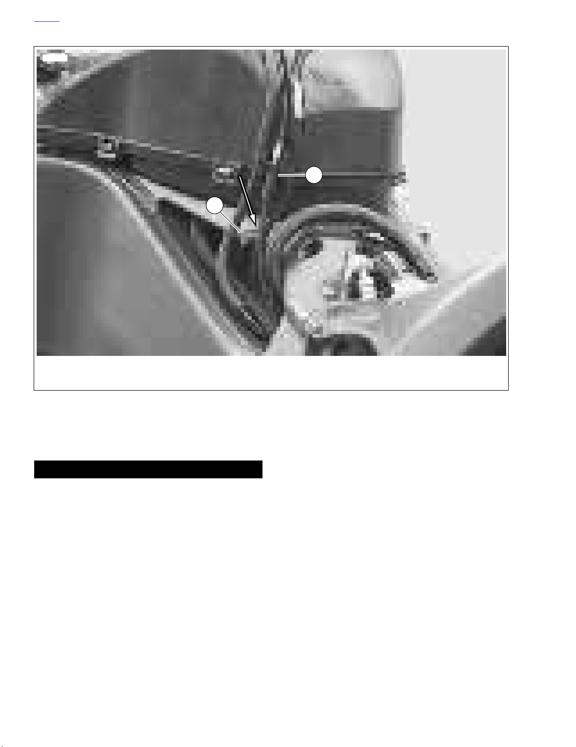
HOME
10514a
1
2
1. Interactive exhaust cable
2. Frame lug
Figure 1-45. Correct Cable Routing Behind Frame Lug
11. See Figure 1-45. Ver ify that the interactive exhaust cable
(1) is routed behind the frame lug (2) before installing air
intake cover.
CAUTION
If cable is routed in front of the frame lug it will cause the
muffler valve to sta y open not allo wing it to w ork properly.
12. Install air intake cover.
1-42 2004 Buell Lightning: Maintenance
Page 91
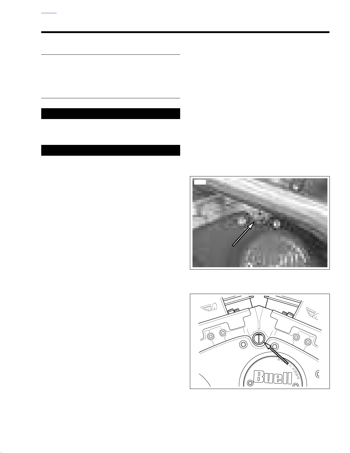
HOME
8351
b0965x1x
IGNITION TIMING 1.18
INSPECTION
Check ignition timing: after each removal of the cam position
sensor.
CHECKING STATIC TIMING
1CAUTION
Always wear proper eye protection when drilling. Flying
debris may result in minor or moderate injury.
CAUTION
Carefully drill hole , applying minimum pressure to drill
out timer plate cover rivets. Applying too much pressure
will damage cam position sensor and/or timer plate and
cover.
NOTES
●
It is not necessary to remove the spark plug to determine
TDC compression stroke of the front cylinder in the following procedure.
11. If engine is coming up on the compression strok e for the
REAR (incorrect) cylinder, the screen will be displa ying
HIGH - 5 volts as timing mar k is just coming into vie w at
left edge of windo w and will s witch to LO W - 0 v olts at
same point as the timing mar k continues through the
window. (If this is obser ved, turn flywheel orward one
revolution to bring engine to compression stroke for front
cylinder.)
NOTES
If timing mark check point is overshot, bump flywheel
●
backwards till TDC mark is at left edge of inspection window and repeat test bumping flywheel in forward (normal) direction.
Never confirm timing while bumping flywheel backwards.
●
This will give you an incorrect reading.
12. If timing is correct, install timing inspection plug and
tighten to 120-180
rect, see ADJUST TIMING in this section.
in-lbs
(14-20 Nm). If timing is not cor-
Do not remove the timing inspection cover to check the
●
static timing. If timing must be corrected, the inspection
plate will then be removed.
1. Raise rear wheel using a lift or jac king point. Tie down
motorcycle for additional support.
2. Remove timing inspection plug.
3. Place transmission in 5th gear.
4. Raise sidestand.
5. Connect Digital Technician to data por t on motorcycle
and select the Static Timing procedure screen.
6. Turn on ignition and mo ve handlebar stop s witch to the
run position. Listen for fuel pump cycling to confi m ignition is active.
7. Turn or gently b ump the flywheel in a orward direction
using the rear wheel. Position the flywheel TDC mark at
the very left edge of the inspection hole.
8. If the engine is coming up on the compression strok e for
the FRONT (correct) cylinder, the screen will be displaying LOW - 0 volts with timing mark at left edge of window.
9. Gently bump flywheel orward in tiny increments.
Figure 1-46. Timing Plug
Figure 1-47. Correct Timing
10. See Figure 1-47. If the static timing is correct, the screen
will switch to HIGH - 5 v olts at the precise moment the
timing mark exactly centers in the inspection window.
2004 Buell Lightning: Maintenance 1-43
Page 92
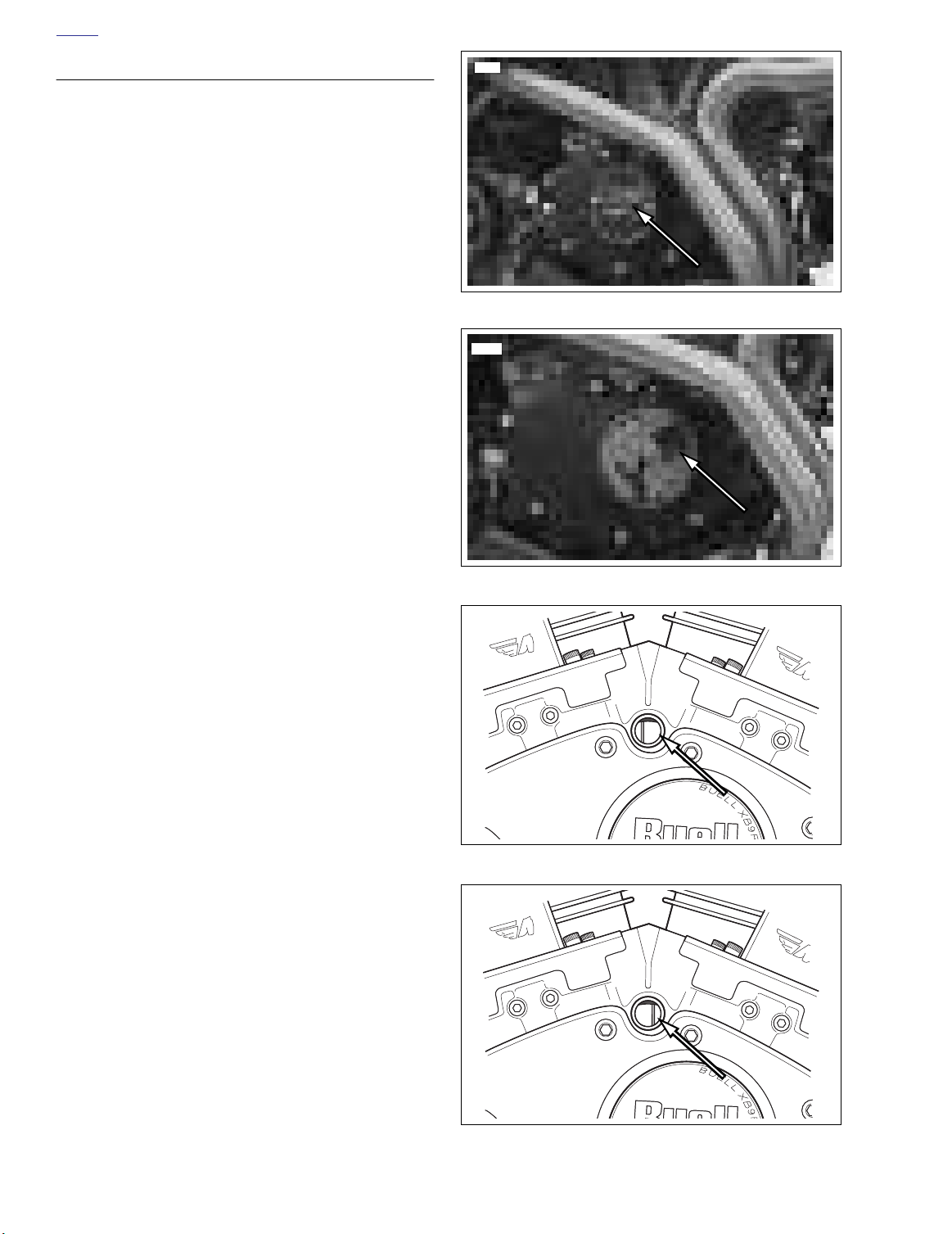
HOME
ADJUST TIMING
1. See Figure 1-48. Remove timing plate cover.
a. Drill rivets holding the timing plate cover.
b. Using a hook, remove timing plate cover.
2. See Figure 1-50. If timing is advanced (mark appears on
left side of window) rotate timing plate counterclockwise.
3. Check timing. See CHECKING STATIC TIMING.
4. See Figure 1-51. If timing is retarded (mar k appears on
right side of window) rotate timing plate clockwise.
5. Recheck timing.
8363
Figure 1-48. Timer Cover
8391
b0964x1x
b0963x1x
Figure 1-49. Cam Position Sensor
Figure 1-50. Advanced Timing
1-44 2004 Buell Lightning: Maintenance
Figure 1-51. Retard Timing
Page 93
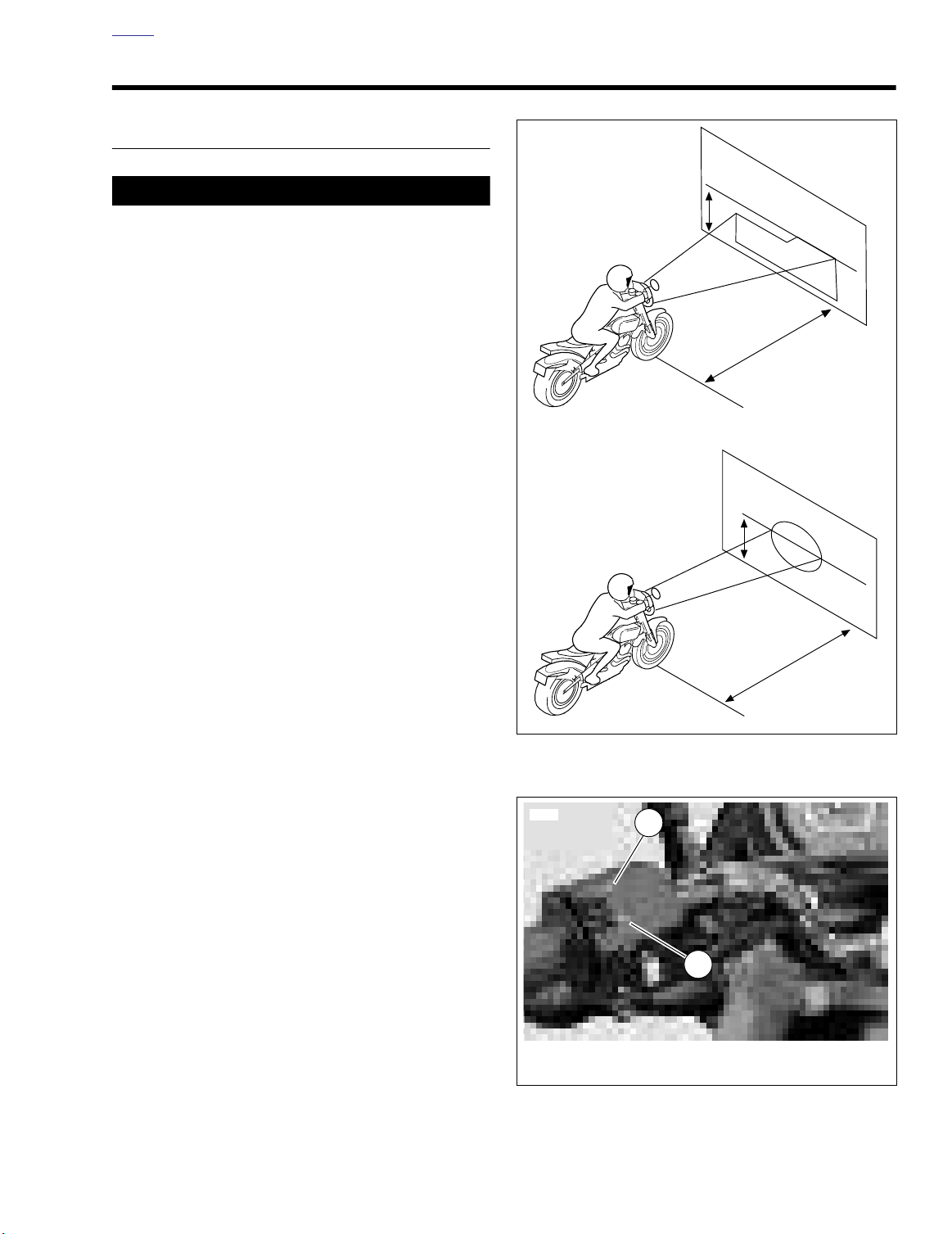
HOME
Position
Motorcycle
25 ft (7.6 m)
b0949x1x
Horizontal Line
29-31 in.
(74-79 cm)
High Beam
Low Beam
Horizontal Line
29-31 in.
(74-79 cm)
Position
Motorcycle
25 ft (7.6 m)
9960
1. High beam
2. Low beam
1
2
HEADLIGHTS 1.19
INSPECTION
1WARNING1WARNING
Do not modify ignition/light s witch wiring to cir cumvent
the automatic-on headlight f eature. High visibility is an
important consideration for motorcycle riders. Failure to
have headlight on at all times could cause an accident,
resulting in death or serious injury.
Check headlights for proper alignment:
●
When the new owner takes delivery of the motorcycle.
●
When there is a change in load (adding luggage, etc.).
1. In a location with lo w light, dr aw a hor izontal line on a
screen or wall that measures 29-31 in. (74-79 cm) above
floo .
2. See Figure 1-52. Position motorcycle 25 ft (7.6 m) a way
from a screen or wall by measuring the distance from the
front axle to the screen/wall.
3. Verify correct front and rear tire pressure. See 1.8 TIRES
AND WHEELS.
4. Load vehicle with r ider/passenger/cargo/accessories.
Weight will compress vehicle suspension slightly.
5. Stand motorcycle upr ight with headlights aimed str aight
forward.
6. Check LOW beam (right lens) for alignment.
a. See Figure 1-53. Tu rn ignition switch to IGN. Set
b. Check that the correct patter n of light is a doub le
c. Adjust headlight alignment. See ADJUSTMENT
7. Check HIGH beam (left) for alignment.
a. See Figure 1-53. Set handlebar headlamp switch to
Low beam lamp will not stay illuminated when high beam is
activated.
b. Check that the correct patter n of light is a circular
c. Adjust headlamp alignment. See ADJUSTMENT
handlebar headlamp switch to LOW beam position.
rectangular pattern and is aligned with the horizontal
line as shown in Figure 1-52.
which follows.
HIGH beam position.
pattern and is centered on the hor izontal line as
shown in Figure 1-52.
NOTE
section.
Figure 1-52. Checking Headlight Alignment
Figure 1-53. Headlamp Switch
2004 Buell Lightning: Maintenance 1-45
Page 94
HOME
ADJUSTMENT
Horizontal Alignment
See Figure 1-54. Loosen fasteners on r ight and left side of
headlight housing to adjust the horizontal alignment.
Vertical Alignment
See Figure 1-55. Loosen fastener on the bottom of headlight
housing to adjust the vertical alignment.
NOTE
Only loosen headlamp alignment fasteners enough to adjust
headlamp. Once headlights are aligned, tighten fasteners to
48-72
in-lbs
(5-8 Nm).
9949
9950
Figure 1-54. Horizontal Headlamp Adjustment
9951
1-46 2004 Buell Lightning: Maintenance
Figure 1-55. Vertical Headlamp Adjustment
Page 95
HOME
8390
THROTTLE POSITION SENSOR (TPS) 1.20
INSPECTION
1. Connect vehicle to Digital Technician.
2. Select data monitor screen.
3. Select TP degrees on screen.
4. Ignition and run switch should be in the on position with
engine off and throttle in the closed position.
NOTE
If closed throttle TP degree reading is not between 5.1° - 6.2°,
TPS should be re-calibrated. See ADJUSTMENT below.
ADJUSTMENT
1. Connect vehicle to Digital Technician.
2. Select calibrations screen/TPS Function.
3. Select Buell TPS zero tab.
4. Select TP volts on screen.
5. See Figure 1-56. Back off idle adjustment until TP volts
and then contin ue to back out one full
stop decreasing
turn.
6. Open and
This is to ensure that the throttle plate is completely closed
before beginning recalibration.
7. With ignition and r un switch in the on position with
engine off and throttle in the closed position press the
TPS zero button at the bottom of the screen.
8. Select TPS zero button and perform TPS zero.
When calibration is complete, dialogue box will appear on
Digital Tech screen with message display “Command Sent
Successfully”. Press OK.
9. Turn idle adjustment cab le screw clockwise until TPS
degrees read 5.2-5.6 degrees.
10. Run vehicle until engine temperature is at 285
C).
11. Set idle to 1050-1150 RPM.
snap shut
throttle control grip 2-3 times.
NOTE
NOTE
°
F (140°
Figure 1-56. Idle Adjuster (behind left fork)
2004 Buell Lightning: Maintenance 1-47
Page 96

HOME
STORAGE 1.21
GENERAL
1WARNING1WARNING
Gasoline is flamma le. Do not store motor cycle having
gasoline in tank within the home or gara ge where open
flames pilot lights, sparks or electric motors are present.
Inadequate safety precautions ma y cause an accident
which could result in death or serious injury.
If the motorcycle will not be oper ated for several months,
such as dur ing the winter season, there are se veral things
which should be done to protect par ts against corrosion, to
preserve the batter y and to pre vent the b uildup of gum and
varnish in the fuel system.
1. Fill fuel tank and add a gasoline stabilizer. Use one of the
commercially available gasoline stabiliz ers following the
manufacturer’s instructions. Run engine until treated
gasoline has had a chance to reach fuel injectors.
2. Remove battery and charge as needed to maintain the
correct voltage. See 1.5 BATTERY MAINTENANCE.
3. Remove the spark plugs, inject a few squirts of engine oil
into each cylinder and cr ank the engine 5-6 re volutions.
Reinstall spark plugs. See 1.14 SPARK PLUGS.
4. Adjust primary chain. See 1.11 PRIMARY CHAIN.
5. Check tire inflation See 1.8 TIRES AND WHEELS. If the
motorcycle will be stored f or an extended period of time,
securely support the motorcycle so that all w eight is off
the tires.
REMOVAL FROM STORAGE
1WARNING1WARNING
After extended periods of stora ge and prior to star ting
vehicle, place transmission in g ear, disengage clutch
and push vehic le back and f orth a f ew times to ensure
proper clutch disengagement. Improper clutch disengagement could result in death or serious injury.
1. Charge and install batter y. See 1.5 BATTERY MAINTE-
NANCE.
2. Remove and inspect spar k plugs. Replace if necessar y.
See 1.14 SPARK PLUGS.
3. Inspect air filter element Replace if necessary. See 1.15
AIR CLEANER FILTER.
4. If fuel tank was drained, fill fuel tank with fresh gasolin .
5. Start the engine and r un until it reaches nor mal operating temperature. Check fluids and refill to proper vels if
required.
a. Check engine oil le vel. See 1.6 ENGINE LUBRICA-
TION SYSTEM.
b. Check transmission fluid l vel. See 1.9 CLUTCH.
6. Perform all of the chec ks in the PRE-RIDING CHECK
LIST in the Owner’s Manual.
1WARNING1WARNING
Do not apply any oil to brake rotors or brake pads. Oil on
brake pads degrades braking efficien y and can result in
an accident which could result in death or serious injury.
6. Wash molded-in-color and chrome-plated surf aces.
Apply a light film of oil to xposed uncoated metal surfaces.
7. If motorcycle is to be co vered, use a mater ial that will
breathe, such as light can vas. Plastic mater ials that do
not breathe promote the formation of condensation.
1-48 2004 Buell Lightning: Maintenance
Page 97

HOME
TROUBLESHOOTING 1.22
GENERAL
The following check list can be helpful in locating most operating troubles. Refer to the appropr iate sections in this Service Manual for detailed procedures.
ENGINE
Starter Motor Does Not Operate or Does
Not Turn Engine Over
1. Engine stop switch in OFF position.
2. Ignition key switch not ON.
3. Discharged battery or loose or corroded connections .
(Solenoid chatters.)
4. Starter control relay or solenoid not functioning.
5. Electric starter shaft pinion gear not engaging or o verrunning clutch slipping.
6. Clutch lever not pulled in. Vehicle in gear.
7. Starter interlock circuit malfunction.
Engine Turns Over But Does Not Start
NOTE
See 4.11 ENGINE CRANKS BUT WILL NOT START for spe-
cific tests.
1. Fuel tank empty.
2. Discharged battery, loose or broken battery terminal connections.
3. Fouled spark plugs.
4. Loose or shorting spark plug cables or connections.
5. Ignition timing badly out of adjustment.
6. Loose wire connection at coil or batter y connection or
plug between ignition sensor and module. See Section 4.
7. Ignition coil not functioning.
8. Ignition module not functioning.
9. Ignition sensor not functioning.
10. Sticking or damaged valve or valves.
11. Engine oil too heavy (winter operation).
12. Ignition circuit interlock malfunction.
13. No output from the ECM. See dealer.
14. Inadequate fuel pressure in fuel lines (possib le leak).
See dealer.
15. Clogged fuel filte . See dealer.
16. Clogged fuel injectors. See dealer.
17. Tripped bank angle sensor. Turn key to OFF, wait 15 seconds, and then back to IGN again to start bike.
18. TP Sensor/fast idle screw not set properly. See dealer.
19. No output from CMP sensor. See dealer.
20. Inoperative fuel pump. See dealer.
Starts Hard
1. Spark plugs in bad condition, ha ve improper gap or are
partially fouled.
2. Spark plug cables in bad condition and shorting.
3. Battery nearly discharged.
4. Loose wire connection at one of the batter y terminals, at
coil or at plug between ignition sensor and module.
5. Throttle controls not adjusted correctly.
6. Ignition coil not functioning.
7. Engine oil too heavy (winter operation).
8. Ignition not timed properly. See dealer.
9. Vapor vent valve plugged or fuel line closed off restricting
fuel fl w.
10. Water or dirt in fuel system.
11. Air leak at intake manifold.
12. Valves sticking.
13. TP Sensor and/or f ast idle scre w not set proper ly. See
dealer.
14. Oxygen, IAT or ET sensors damaged or malfunctioning.
See dealer.
Starts But Runs Irregularly or Misses
NOTE
See 4.15 MISFIRE for specific tests.
1. Spark plugs in bad condition or partially fouled.
2. Spark plug cables in bad condition and shorting.
3. Spark plug gap too close or too wide.
4. Ignition coil not functioning.
5. Ignition module not functioning.
6. Ignition sensor not functioning.
7. Battery nearly discharged.
8. Damaged wire or loose connection at batter y terminals
or coil.
9. Intermittent short circuit due to damaged wire insulation.
10. Water or dirt in fuel system and throttle body or filte .
11. Vapor vent valve plugged.
12. Throttle controls improperly adjusted.
13. Air leak at intake manifold or air filte .
14. Damaged intake or exhaust valve.
15. Weak or broken valve springs.
16. Incorrect valve timing.
17. Oxygen, IAT or ET sensors damaged or malfunctioning.
See dealer.
18. TP Sensor not set properly. See dealer.
19. Fuel level too low. Add gasoline.
20. Inoperative fuel injector. See dealer.
21. Obstructed fuel tank v ent valve or pinched v ent tube.
See dealer.
2004 Buell Lightning: Maintenance 1-49
Page 98

HOME
Spark Plug Fouls Repeatedly
1. Incorrect spark plug.
2. Piston rings badly worn or broken.
3. Valve stem seals worn or damaged.
4. Valve guides badly worn.
5. Sensors damaged.
Pre-Ignition or Detonation
(Knocks or Pings)
1. Excessive carbon deposit on piston head or comb ustion
chamber.
2. Incorrect heat range spark plug.
3. Spark plugs not fi ing.
4. Ignition timing advanced.
5. Fuel octane rating too low.
6. Intake manifold vacuum leak.
Overheating
1. Insufficient oil supply or oil not circulating
2. Clogged or damaged fins on oil coole .
ENGINE LUBRICATION SYSTEM
Oil Does Not Return To Oil Tank
1. Oil tank empty.
2. Return pump gears damaged.
3. Oil feed pump not functioning.
4. Restricted oil lines or fitting .
Engine Uses Too Much Oil or
Smokes Excessively
1. Piston rings badly worn or broken.
2. Valve stem seals worn or damaged.
3. Valve guides worn.
Engine Leaks Oil From Cases, Push Rods,
Hoses
1. Loose parts.
2. Imperfect seal at gaskets, push rod co ver, washers, etc.
To aid locating leaks, use BLACK LIGHT LEAK DETECTOR (Part No. HD-35457).
3. Restricted oil return line to tank.
4. Restricted breather passage(s) to air cleaner.
3. Cooling fan not operating properly.
4. Leaking valves.
5. Heavy carbon deposit.
6. Ignition timing retarded.
Valve Train Noise
1. Hydraulic lifter not functioning properly.
2. Bent push rod.
3. Cam, cam gears or cam bushings worn.
4. Rocker arm binding on shaft.
5. Valve sticking in guide.
Excessive Vibration
1. Engine tie-bars loose, broken or improperly spaced.
2. Isolator mounting fasteners loose.
3. Broken frame.
4. Primary chain badly w orn or links tight as a result of
insufficient lub ication.
ELECTRICAL SYSTEM
Alternator Does Not Charge
1. Regulator-rectifier module not functioning
2. Rectifier not grounded.
3. Engine ground wire loose or broken.
4. Loose or broken wires in charging circuit.
5. Stator not functioning.
6. Rotor not functioning.
Alternator Charge Rate Is Below Normal
1. Regulator-rectifier module not functioning
2. Stator not functioning.
3. Rotor not functioning.
4. Weak battery.
5. Loose connections.
FUEL SYSTEM
5. Wheels not aligned and/or tires worn.
6. Internal engine problem.
7. Wheels not balanced correctly.
1-50 2004 Buell Lightning: Maintenance
Poor Fuel Economy
1. Oxygen sensor damaged or malfunctioning (bike running
rich). See dealer.
Page 99

HOME
TRANSMISSION
Shifts Hard
1. Clutch dragging slightly.
2. Shifter forks (inside transmission) damaged.
3. Corners worn off shifter clutch dogs (inside tr ansmission).
Jumps Out of Gear
1. Shifter engaging par ts (inside tr ansmission) badly worn
and rounded.
2. Shifter forks bent.
3. Damaged gears.
CLUTCH
Slips
1. Clutch controls improperly adjusted.
2. Worn friction plates.
Drags or Does Not Release
1. Clutch controls improperly adjusted.
2. Clutch plates excessively warped.
Chatters
1. Friction or steel plates worn, warped or dragging.
CHASSIS
Irregular/Inadequate Brake Action
1. Master cylinder low on fluid
2. Brake line contains air bubbles or moisture.
3. Master or wheel cylinder piston worn.
4. Brake pads covered with grease or oil.
5. Brake pads badly worn to minimum lining thickness.
6. Brake rotor badly worn or warped.
7. Brake pads dragging or e xcessive braking (brake fades
due to heat buildup).
8. Insufficient brake pedal or hand le ver free pla y (brake
drags).
Handling Irregularities
1. Tires improperly inflated See 1.8 TIRES AND WHEELS.
Do not overinflat .
2. Loose wheel axle . Tighten front axle to 39-41 ft-lbs (5356 Nm). Tighten rear axle to 48-52 ft-lbs (65-70 Nm).
3. Excessive wheel hub bearing play.
4. Rims and tires out-of-tr ue sideways (tire r unout should
not be more than 0.080 in. (2.03 mm)).
5. Rims and tires out-of-round or eccentr ic with hub (tire
runout should not be more than 0.060 in. (1.5 mm)).
6. Irregular or peaked front tire tread wear.
7. Tire and wheel unbalanced or w eights on wrong side of
wheel. (Front wheel weights must be on the br ake rotor
side.)
8. Steering head bear ings improperly tightened or w orn.
See 1.13 STEERING HEAD BEARINGS . Check for
proper torque and replace w orn bearings. See 2.17
FORK CLAMPS, UPPER AND LOWER.
9. Shock absorber or front f orks not functioning nor mally
due to incorrect adjustment. See 1.12 SUSPENSION
DAMPING ADJUSTMENTS.
10. Heavy front end loading. Non-standard equipment on the
front end (such as hea vy radio receivers, extra lighting
equipment or luggage) tends to cause unstable handling.
2004 Buell Lightning: Maintenance 1-51
Page 100
HOME
SUSPENSION
When making adjustments , remember there are tw o mediums in setting up a bik e, geometry and suspension. Both
components work together because suspension is a par t of
geometry. In order to solv e handling problems, it is important
to diagnose the problem’s true nature.
Table 1-11. General Suspension Problems
TROUBLESHOOTING CONDITION ADJUSTMENT SOLUTION
Chattering, sliding or an uncomf ortable feeling are suspension-related. Handling and a s winging fork are geometr yrelated, but often these unw anted characteristics can be
solved by suspension adjustments.
The following tables list possib le suspension and oper ating
troubles and their probable causes.
Bike wallows through turns.
Feels loose or vague after bumps.
Wheel tends to “pogo” after passing over a bump. This is noticeable by watching the
bike continue to bounce as it travels over multiple bumps.
Wheel responds to bump, but doesn’t return to ground quickly after bumps. This is
more pronounced over a series of bumps and is often referred to as “packing down.”
The bike bottoms out or dips while cornering.
Bike has excessive brake dive.
Harsh ride particularly over washboard surfaces.
Bumps kick through handlebars or seat.
Suspension seems not to respond to bumps. This is evidenced by tire chattering (a
movement with short stroke and high frequency) through corners or by jolting the rider
over rough roads.
Increase rebound damping.
Reduce rebound damping.
Increase compression damping.
Reduce compression damping.
Table 1-12. Rear Suspension Problems
TROUBLESHOOTING CONDITION ADJUSTMENT SOLUTION
“Pumping on the Rear” occurs when you are accelerating out
of a corner. This problems occurs in two varieties.
1. The first type has a m vement with a long stroke and a
high frequency.
2. The second version has a movement with a short stroke
and high frequency.
Chattering during braking. Decrease the compression damping. If the problem persists,
Lack of tire feedback. The suspension is too soft. Increase compression damping.
Sliding during cornering. Sliding may occur going into the
corner or accelerating out of the corner.
1. The shock is too soft. Increase compression damping. If
the adjuster is already set to the maxim um, add more
preload to the spring (one turn maximum).
2. In this case the shoc k is too hard. Decrease compression damping.
decrease rebound damping for a faster rebound rate. Less
spring preload may also help.
The suspension is too hard. Decrease compression damping.
Table 1-13. Front Suspension Problems
TROUBLESHOOTING CONDITION ADJUSTMENT SOLUTION
Not absorbing bumps. A good suspension is a balance between damping
and track condition. Finding this balance requires
exploring all possible compression settings.
Lack of tire feedback. Increase compression damping.
Tire slides. Decrease compression damping.
1-52 2004 Buell Lightning: Maintenance
 Loading...