

Buderus SU80/5, SU54/5, SU100/5 Installation And Maintenance Instructions Manual
Storage water heater
Acumulador de agua caliente
Préparateur ECS
WARNING:
These installation instructions are intended solely for
use by a licensed heating contractor or service technician. Read all instructions before installing. Perform
steps exactly in the order given. Failure to follow these
instructions can result in severe injury, death or property damage.
PELIGRO:
Este manual de instalación únicamente lo pueden utilizar instaladores de calefacción o técnicos especializados. Antes de la instalación, lea todas las indicaciones.
Realice todas las acciones exactamente en el orden indicado. En caso de incumplimiento, existe riesgo de lesiones graves e incluso de muerte o daños materiales
considerables.
6 720 805 397-00.1ITL
AVERTISSEMENT :
Cette notice d’installation doit être utilisée uniquement
par des installateurs chauffagistes ou des techniciens de
maintenance qualifiés. Lisez attentivement toutes les
consignes avant l’installation. Exécutez les actions précisément dans l’ordre indiqué. En cas de non-respect,
vous risquez de subir de sérieuses blessures pouvant
conduire à la mort ou d’entraîner de lourds dommages
matériels.
SU54/5 | SU80/5 | SU100/5
[en] Installation and maintenance instructions 2
[es] Instrucciones de instalación y de mantenimiento 20
[fr] Notice d'installation et d'entretien 39
6 720 819 292 (2017/11) US/CA/MX
Contents
Contents
1 Safety Considerations and Symbol Descriptions . . . . . . . . . . 2
1.1 Key to symbols . . . . . . . . . . . . . . . . . . . . . . . . . . . . . . . . . 2
1.2 Safety instructions . . . . . . . . . . . . . . . . . . . . . . . . . . . . . . 3
1.3 Instructions for the owner and operator . . . . . . . . . . . . . 4
2 Product Information . . . . . . . . . . . . . . . . . . . . . . . . . . . . . . . . . . . 4
2.1 Scope of delivery . . . . . . . . . . . . . . . . . . . . . . . . . . . . . . . 4
2.2 Designated use . . . . . . . . . . . . . . . . . . . . . . . . . . . . . . . . . 4
2.3 Product Information . . . . . . . . . . . . . . . . . . . . . . . . . . . . . 5
2.4 Data plate . . . . . . . . . . . . . . . . . . . . . . . . . . . . . . . . . . . . . 5
2.5 Pressure drop curve of heating coil . . . . . . . . . . . . . . . . . 5
2.6 Technical Data . . . . . . . . . . . . . . . . . . . . . . . . . . . . . . . . . 6
2.7 Physical and connection dimensions . . . . . . . . . . . . . . . 7
3 Standards, regulations and directives . . . . . . . . . . . . . . . . . . . 8
4 Moving the tank . . . . . . . . . . . . . . . . . . . . . . . . . . . . . . . . . . . . . . 8
5 Installation . . . . . . . . . . . . . . . . . . . . . . . . . . . . . . . . . . . . . . . . . . . 8
5.1 Tank installation . . . . . . . . . . . . . . . . . . . . . . . . . . . . . . . . 8
5.1.1 Requirements for installation location . . . . . . . . . . . . . . 8
5.1.2 Wall clearances . . . . . . . . . . . . . . . . . . . . . . . . . . . . . . . . . 9
5.1.3 Positioning the tank . . . . . . . . . . . . . . . . . . . . . . . . . . . . . 9
5.2 Water connections . . . . . . . . . . . . . . . . . . . . . . . . . . . . . 10
5.2.1 Connecting the tank on the water side . . . . . . . . . . . . . 10
5.2.2 Installing a T&P safety valve (on-site) . . . . . . . . . . . . . . 11
5.3 Install a tank water temperature sensor (accessory) or
aquastat (accessory). . . . . . . . . . . . . . . . . . . . . . . . . . . 11
6 Start-up procedure . . . . . . . . . . . . . . . . . . . . . . . . . . . . . . . . . . . 13
6.1 Commissioning the DHW tank . . . . . . . . . . . . . . . . . . . . 13
9 Maintenance . . . . . . . . . . . . . . . . . . . . . . . . . . . . . . . . . . . . . . . . 13
9.1 Preparing the DHW tank for cleaning . . . . . . . . . . . . . . 13
9.2 Descaling/cleaning the tank . . . . . . . . . . . . . . . . . . . . . . 14
9.3 Checking the magnesium anode . . . . . . . . . . . . . . . . . . 15
9.3.1 Check the top magnesium anode (SU80/5, SU100/5) 15
9.3.2 Check the top magnesium anode (SU54/5) . . . . . . . . . 15
9.3.3 Check the side magnesium anode
(SU80/5, SU100/5) . . . . . . . . . . . . . . . . . . . . . . . . . . . 15
9.4 Startup after maintenance . . . . . . . . . . . . . . . . . . . . . . . 16
10 Spare Parts . . . . . . . . . . . . . . . . . . . . . . . . . . . . . . . . . . . . . . . . . 17
1 Safety Considerations and Symbol
Descriptions
1.1 Key to symbols
Warnings
Warnings in this document are identified by a warning
triangle printed against a grey background.
Keywords at the start of a warning indicate the type and
seriousness of the ensuing risk if measures to prevent
the risk are not taken.
The following keywords are defined and can be used in this document:
• DANGER indicates a hazardous situation which, if not avoided, will
result in death or serious injury.
• WARNING indicates a hazardous situation which, if not avoided,
could result in death or serious injury.
• CAUTION indicates a hazardous situation which, if not avoided, could
result in minor to moderate injury.
• NOTICE is used to address practices not related to personal injury.
Important information
7 Shutdown . . . . . . . . . . . . . . . . . . . . . . . . . . . . . . . . . . . . . . . . . . . 13
7.1 Shutting down the tank . . . . . . . . . . . . . . . . . . . . . . . . . 13
7.2 Shutting down the heating system when there is a risk
of frost . . . . . . . . . . . . . . . . . . . . . . . . . . . . . . . . . . . . . . 13
8 Environmental protection/disposal . . . . . . . . . . . . . . . . . . . . . 13
This symbol indicates important information where
there is no risk to people or property.
Additional symbols
Symbol Explanation
▶ Step in an action sequence
Cross-reference to another part of the document
• List entry
– List entry (second level)
Table 1
SU54.5 | SU80.5 | SU100.5 – 6 720 819 292 (2017/11)2
Safety Considerations and Symbol Descriptions
1
1.2 Safety instructions
Read all instructions before installing. Perform the steps in the indicated
sequence. Have the DHW tank inspected by a trained service technician
at least once every year. Failure to comply with these instructions can
result in severe, possibly fatal, personal injury as well as damage to
property and equipment.
Installation and servicing
▶ Risk of fire from soldering and brazing!
Take appropriate protective measures when soldering and brazing as
the insulation is flammable, for example, cover the insulation.
▶ Ensure that only a licensed contractor installs or services the DHW
tank.
▶ Use installation material with adequate temperature stability.
Forbidden:
Connection of the potentiostat for an impressed current anode to the
magnesium anode installed in a storage tank is absolutely forbidden!
This would destroy the tank! The warranty would be voided.
Installation and commissioning
▶ In the Commonwealth of Massachusetts, the DHW tank must be
installed by a licensed plumber.
▶ Have an electrician connect the electrical system. The wiring diagram
must be followed.
▶ Do not install this device in rooms with a high moisture level
(e.g. bathrooms, saunas).
Function
▶ To ensure that the tank functions properly, heed these installation and
maintenance instructions.
▶ Never close the blow-off line of the T&P safety valve. For safety
reasons, water may escape during heating.
Danger from electric shock
▶ Only electricians may work on the electrical system.
▶ Before performing electrical work, disconnect the power and secure
the unit against unintentional reconnection.
▶ Ensure the system has been disconnected from the power supply.
Risk of scalding at the hot water draw-off point
▶ When the DHW tank is in operation, temperatures in excess of 122 °F
(50 °C) can occur. To limit the temperature at the tap, install a
thermostatic DHW mixing valve.
▶ Water heated for washing the laundry, dishes and for other cleaning
purposes can cause scalding and permanent injuries.
▶ Children, elderly, and handicapped persons are more likely to be
permanently injured by hot water. Never leave such individuals in the
tub or shower unattended under any circumstances. Children must
not be allowed to operate hot water faucets themselves or to fill a
bathtub.
▶ If the building has occupants in the above groups who operate hot
water faucets, or state laws / local ordinances stipulate specific water
temperatures, take the following precautions:
– Use the lowest possible temperature setting.
– To prevent scalding, install a tempering device, such as an
automatic mixing valve, at hot water tap or water heater. Select and
install the automatic mixing valve in accordance with the valve
manufacturer's recommendations and instructions.
▶ Water exiting from drain valves can be extremely hot. To avoid
injuries:
– Check that all connections are tight.
– Direct exiting water away from people.
▶ Measures must be taken to protect against excessive temperature and
pressure! Installation of a T&P safety valve is required.
The chart below shows the relationship between water temperature and
time until there is a risk of scalding. It can be used as the basis for
determining the safest water temperature for your application.
Temperature Time to severe scalding
120 °F (48 °C) longer than 5 minutes
125 °F (51 °C) 1.5 to 2 minutes
130 °F (54 °C) approx. 30 seconds
135 °F (57 °C) approx. 10 seconds
140 °F (60 °C) less than 5 seconds
145 °F (62 °C) less than 3 seconds
150 °F (65 °C) approx. 1.5 seconds
155 °F (68 °C) approx. 1 second
Table 2 Approximate time-temperature relationship until there is a risk
of scalding
1) Source: Moritz, A.R. and Henriques, F.C., Jr. (1947). Studies of thermal injury. II.
The relative importance of time and surface temperature in the causation of
cutaneous burns, Am J of Pathol, 23, 695-720.
1)
To protect against corrosion and ensure compliance with the rules for
electrical safety, observe the following points:
▶ Use metal fittings for drinking water heating systems with plastic
piping.
▶ Use only original accessories from the manufacturer.
▶ When installation of the tank is complete, inspect the ground
conductor (including metal fittings).
Maintenance
Customers are advised to:
▶ Sign a maintenance and inspection contract with an authorized
contractor. Inspect and maintain the DHW tank as necessary on a
yearly basis. Service as needed.
▶ Use only original spare parts.
Flooding
▶ After a flood, do not use the appliance if any part has been
submerged. Damage to appliances that have been submerged can be
quite severe and pose numerous safety risks.
▶ An appliance that was subject to flooding must be replaced.
Corrosion
▶ To reduce oxygen permeation and therefore corrosion to a minimum,
do not use vapour-permeable components!
SU54.5 | SU80.5 | SU100.5 – 6 720 819 292 (2017/11) 3
2
Product Information
1.3 Instructions for the owner and operator
WARNING: Risk of scalding at the taps!
There is a risk of scalding at the taps if the tank
temperature is set above 122 °F (50 °C) and during
thermal disinfection.
▶ Advise users that they should draw off only mixed
water. Otherwise, install a thermostatic DHW mixing
valve.
NOTICE: Risk of tank damage from excessively high
pressure.
▶ Never plug the blow-off line of the T&P safety valve.
▶ Explain the operation and handling of the heating system and DHW
tank, making a particular point of safety-relevant features.
▶ Explain the function and how to check the T&P safety valve.
▶ Hand all enclosed documents over to the owner/operator.
▶ Recommendation for the user: Sign a maintenance and inspection
contract with a licensed contractor.
▶ Highlight the following for the user:
– Water may be discharged from the T&P safety valve during heat-up.
– The blow-off line on the T&P safety valve must always be kept open.
– Check that the T&P safety valve operates properly at least once
yearly.
– The tank must be inspected annually and maintained as required.
2 Product Information
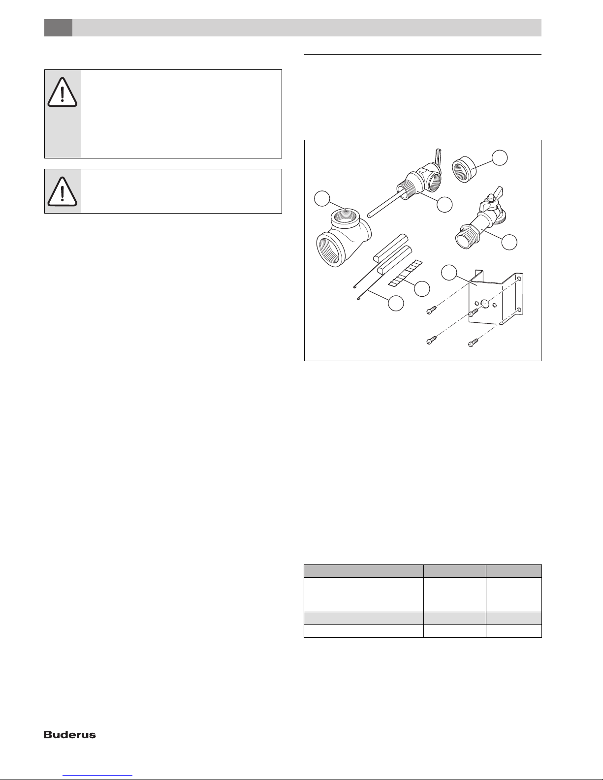
2.1 Scope of delivery
• Tanks
• Installation and Maintenance Instructions
• B-KIT
3
1
2
4
5
6
7
6 720 805 397-01.1ITL
Fig. 1 B-kit
[1] Tee 1" x 1" x ¾ " (2x)
[2] Temperature and pressure relief valve
[3] Cap ¾ "
[4] Drain valve
[5] Holder for Aquastat, screws for Aquastat holder (4x)
[6] Compensation fields for aquastat or tank temperature sensor
[7] Quarter-circle spacer for aquastat or tank temperature sensor
(2x)
2.2 Designated use
The tank is designed for heating and storing drinking water. Please
observe national, regional, and local codes, regulations, guidelines and
standards for potable water.
Install this tank only in sealed unvented hydronic heating systems.
Any other purpose is considered improper use. Any resulting damage is
excluded from the manufacturer's warranty.
Requirements for drinking water Unit
Water hardness, min. ppm
grain/US gallon
°dH
pH value, min. – max. 6.5 – 9.5
Conductivity, min. – max. μS/cm 130 – 1500
Table 3 Requirements for drinking water
SU54.5 | SU80.5 | SU100.5 – 6 720 819 292 (2017/11)4
36
2.1
2
2.3 Product Information
Product Information
2
14
13
12
11
10 10
7
1
12
11
2
3
4
5
6
8
14
1
2
3
4
9
5
7
6
SU 54/5 SU80/5, SU100/5
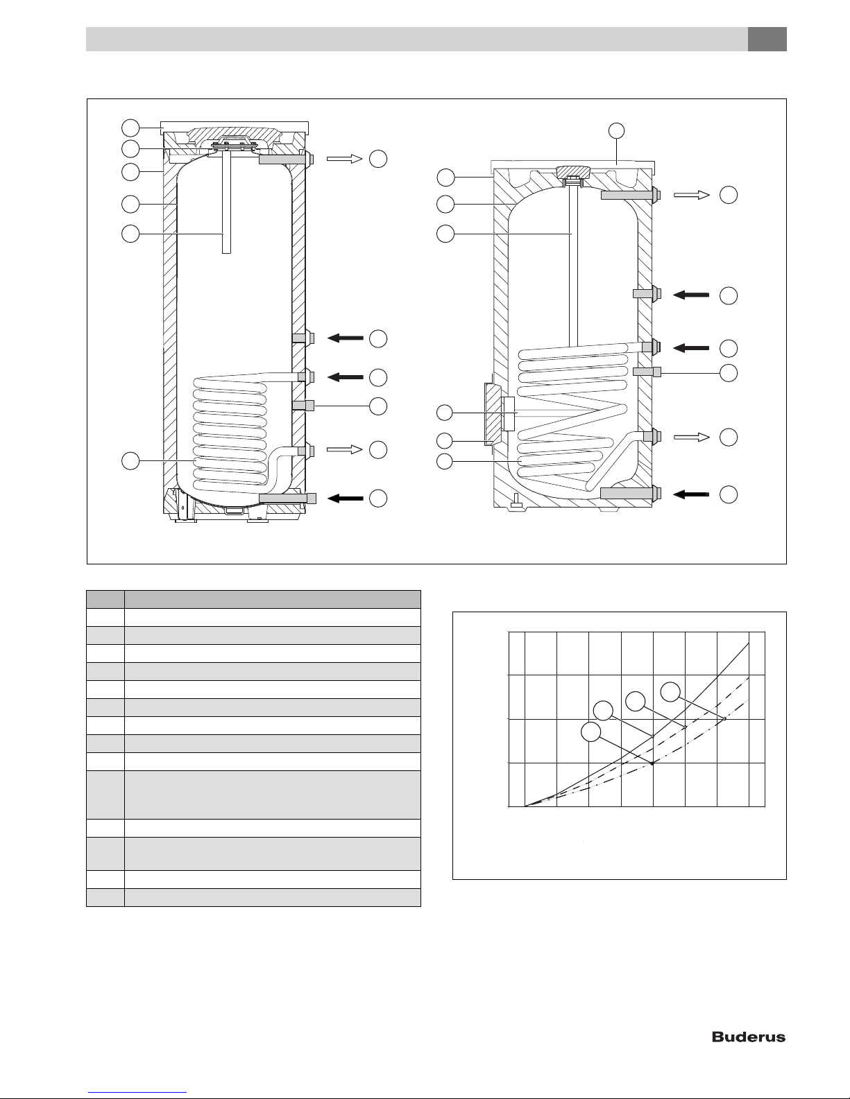
Fig. 2 Product Information
Item Description
1 DHW outlet
2 Recirculation connection
3 Boiler supply
4 Sensor well for temperature sensor
5 Boiler return
6 Cold water inlet
7 Heat exchanger for heating by boiler, smooth enameled tubing
8 Inspection port for service and cleaning at the front
9 2nd anode in inspection port, with insulation
10 SU54/5: 2x electrically insulated installed magnesium anode
SU80, SU100/5: electrically uninsulated installed magnesium
anode
11 Tank, enameled steel
12 Jacket, painted sheet metal with rigid polyurethane foam
insulation, 2" (50 mm)
13 Inspection port for service and cleaning
14 PS top cover
Table 4 Product Information
2.4 Data plate
The data plate is located at the top rear of the DHW tank.
2.5 Pressure drop curve of heating coil
8
6
3
2
4
1
A
2
Pressure drop [ft of head]
Pressure drop [ft of head]
0
2
46810121416
flow rate [gpm]
ow rate [gpm]
Fig. 3 Pressure drop curve
[1] SU100/5
[2] SU80/5
[3] SU54/5
Example:
[A] 10 gpm, 2 ft of head
6 720 805 397-02.1ITL
6 720 805 397-08.1ITL
SU54.5 | SU80.5 | SU100.5 – 6 720 819 292 (2017/11) 5
2
Product Information
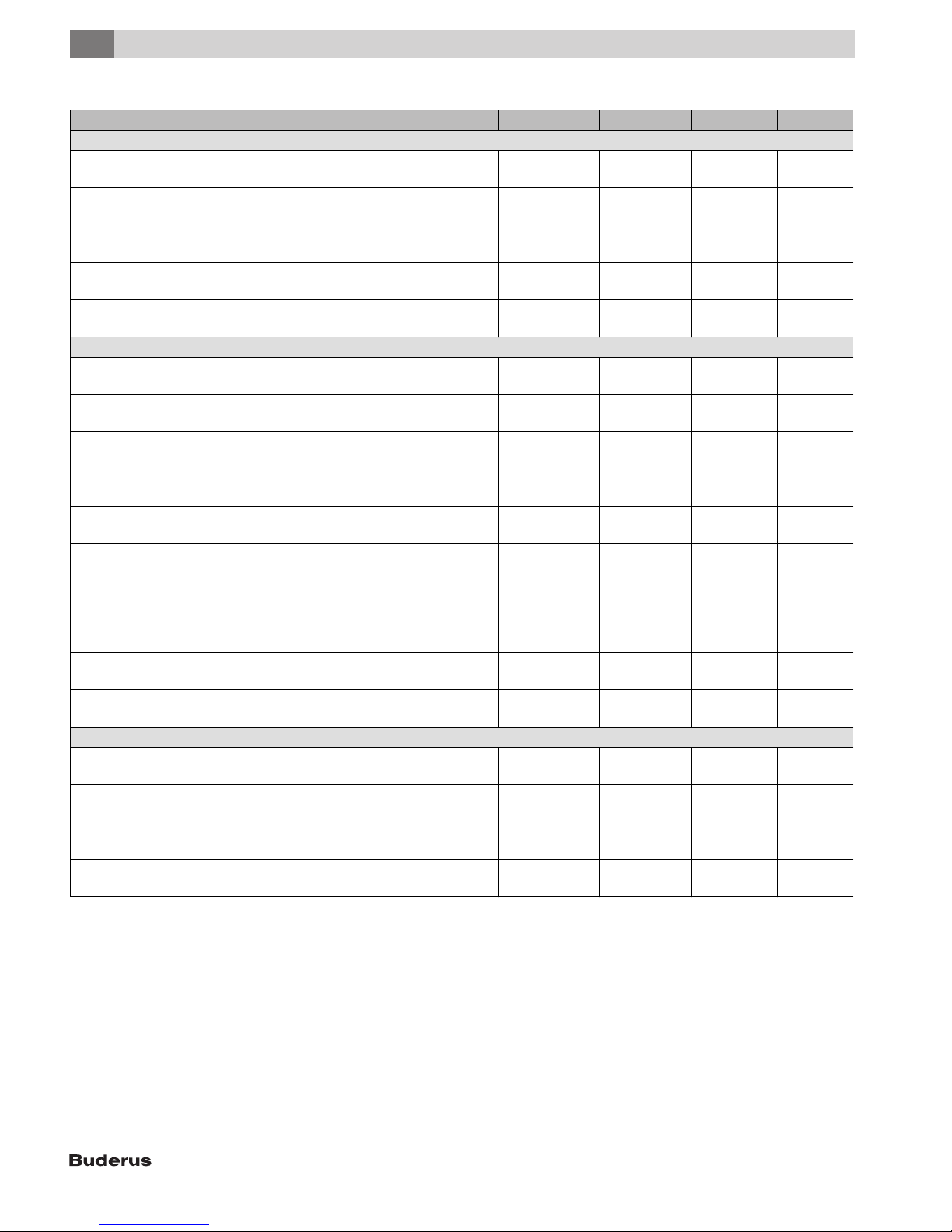
2.6 Technical Data
Unit SU54/5 SU80/5 SU100/5
Tank capacity
Tank capacity (total) gal
(l)
Maximum flow rate gpm
(l/min)
Maximum DHW temperature °F
( °C)
Maximum operating pressure DHW psi
(bar)
Standby heat loss (149 °F (65 °C) DHW temperature, 68 °F (20 °C) room
temperature)
DHW tank performance at:
Domestic cold water inlet temperature °F
Domestic hot water outlet temperature °F
DHW temperature rise °F
Heat exchanger supply temperature (heating water) °F
Flow rate (heating water) gpm
Pressure drop (heating water) foh
Continuous rating gph
Amount that can be drawn off in the first hour gph
Maximum heat input btu/hr
Heat exchanger
Content gal
Surface area ft
Maximum heating water temperature °F
Max. operating pressure, heat exchanger psi
Table 5 Technical Data
°F/h
(K/h)
( °C)
( °C)
( °C)
( °C)
(l/h)
(mbar)
(l/h)
gpm
(l/min)
(l/h)
(kW)
(l)
(m2)
( °C)
(bar)
51.3
(194)
5.1
(19)
203
(95)
150
(10.3)
0.6
(0.33)
50
(10)
140
(60)
90
(50)
176
(80)
11.4
(2600)
2.4
(72)
130
(462)
2.00
(8.2)
180
(680)
84 879
(24.9)
1.5
(5.7)
2
9.69
(0.9)
230
(110)
232
(16)
77.4
(293)
7.7
(29)
203
(95)
150
(10.3)
0.5
(0.28)
50
(10)
140
(60)
90
(50)
176
(80)
11.4
(2600)
2.7
(81)
189
(484)
2.10
(11.9)
264
(1000)
119 217
(34.9)
2.3
(8.7)
13.99
(1.3)
230
(110)
232
(16)
98.4
(372)
9.8
(37)
203
(95)
150
(10.3)
0.4
(0.23)
50
(10)
140
(60)
90
(50)
176
(80)
14
(3180)
3.8
(114)
218
(787)
3.05
(13.7)
312
(1180)
143 872
(42.2)
3.1
(11.7)
19.38
(1.8)
230
(110)
232
(16)
SU54.5 | SU80.5 | SU100.5 – 6 720 819 292 (2017/11)6
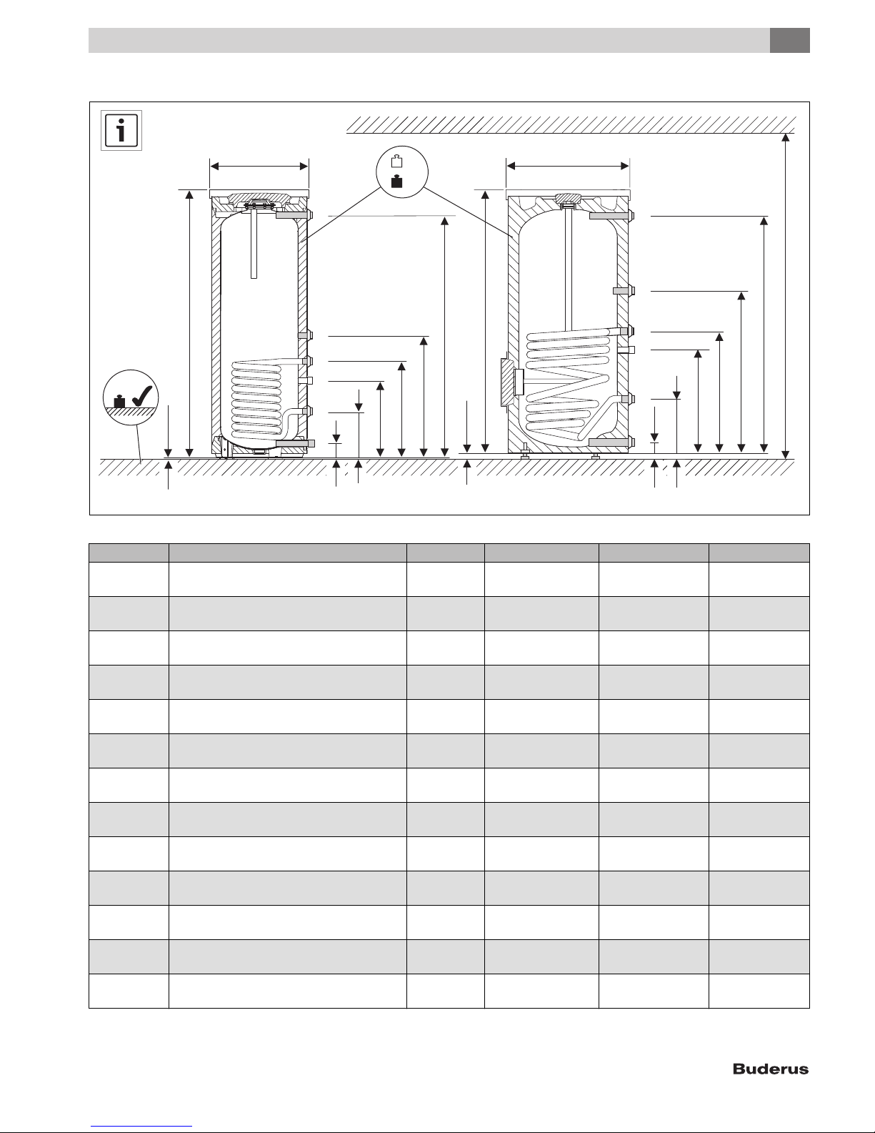
2.7 Physical and connection dimensions
Product Information
2
A
1"
D
¾"
1"
B
C
SU 54/5 SU80/5, SU100/5
¾"
1"
1"
E
F
L
M
D
J
I
H
G
C
A
1"
¾"
1"
¾"
1"
1"
H
G
E
F
J
I
6 720 805 397-03.4TT
Fig. 4 Physical and connection dimensions
Item Description Unit SU54/5 SU80/5 SU100/5
A Diameter inch
(mm)
B Minimum floor weight carrying capacity Ib
(kg)
C Clearance off floor inch
(mm)
D Overall height inch
(mm)
E Height, cold water inlet inch
(mm)
F Height, tank return inch
(mm)
G Height, sensor well for temperature sensor inch
(mm)
H High boiler supply inch
(mm)
i Height, recirculation connection inch
(mm)
J Height, hot water outlet inch
(mm)
K Minimum room height for anode replacement inch
(mm)
V Weight (empty) lb
(kg)
M Weight (full) lb
(kg)
21-3/4
(550)
628
(284)
1/2
(12.5)
60-1/4
(1530)
3-1/4
(80)
10-1/2
(265)
17-1/8
(433)
21-7/8
(553)
27-3/4
(703)
56.4
(1399)
74-1/4
(1880)
160.9
(73)
601.9
(273)
26-3/8
(670)
893
(405)
3/8 - 3/4
(12.5)
58-7/8
(1495)
3-1/8
(80)
12-1/2
(318)
31-1/5
(617)
28-1/2
(722)
35-1/2
(903)
53-3/8
(1355)
72-7/8
(1850)
231.5
(105)
892.9
(405)
26-3/8
(670)
1122
(509)
3/8 - 3/4
(12.5)
72-1/4
(1835)
3-1/8
(80)
12-1/2
(318)
24-3/10
(793)
35-3/8
(898)
45
(1148)
66-3/4
(1695)
82-3/4
(2100)
282.2
(128)
1142
(518)
Table 6 Physical and connection dimensions
K
SU54.5 | SU80.5 | SU100.5 – 6 720 819 292 (2017/11) 7
3
Standards, regulations and directives
3 Standards, regulations and directives
Observe all national, state, and local code, regulations
and standards applicable to installation and operation of
the tank!
All electrical components must be approved for the USA
and Canada.
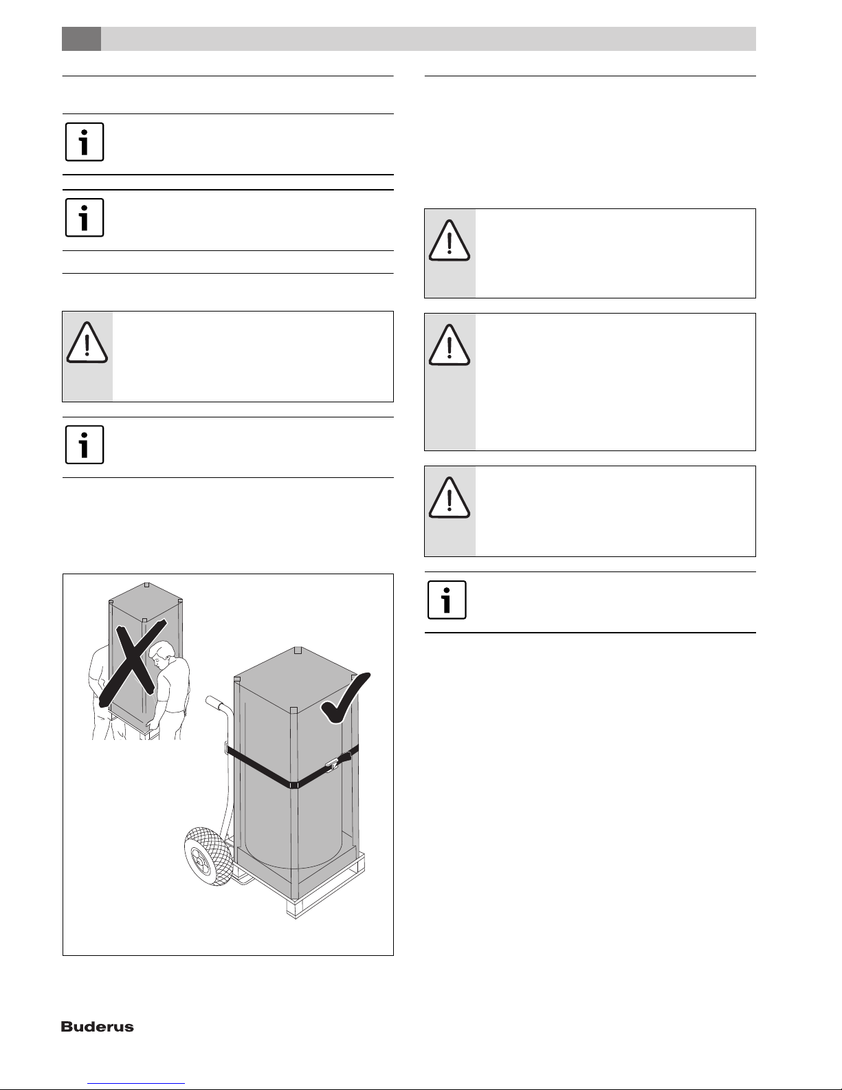
4 Moving the tank
WARNING: Risk of injury from carrying heavy loads and
inadequately securing loads for transport!
▶ Use suitable means of transportation, e.g. a dolly with
strap.
▶ Secure the load against falling.
Where possible, do not remove the DHW tank from its
packaging until it has reached the installation location.
This ensures protection during handling.
▶ Position the dolly at the back of the packed DHW tank.
▶ Secure the DHW tank to the means of transportation with a strap.
▶ Transport the DHW tank to the installation location.
▶ Only remove the DHW tank from the packaging at the installation
location.
5 Installation
The tank is delivered fully assembled.
▶ Check that the tank is complete and undamaged.
5.1 Tank installation
5.1.1 Requirements for installation location
NOTICE: Risk of damage from inadequate load-bearing
capacity of the supporting substructure or unsuitable
floor surface!
▶ Ensure that the installation area is level and offers
sufficient load-bearing capacity.
NOTICE: Risk of damage from stress cracking and
corrosion!
▶ Position the DHW tank in a dry room free from the risk
of freezing.
▶ Install the tank only in closed-loop, unvented hydronic
heating systems.
▶ Open expansion vessels may NOT be used with this
tank.
NOTICE: If leaks can result in property damage or a drain
pan is required by law:
▶ Install an adequate drain pan.
▶ Follow the installation instructions of the drain pan
manufacturer.
Fig. 5 Transporting with a dolly
Install an adequate drain pan if required by code, or if a
leak could result in property damage. Follow drain pan
manufacturer's instructions.
▶ Place the DHW tank on a plinth if there is any danger of water
collecting on the floor of the setup site.
▶ The installation site must be a dry and frost-free room.
▶ Observe minimum room height ( Tab. 6, page 7) and minimum wall
clearance in installation room ( Fig. 6).
▶ Maintain a distance of 2" (51 mm) from heated pipes and combustible
surfaces.
6 720 800 035-03.1ITL
SU54.5 | SU80.5 | SU100.5 – 6 720 819 292 (2017/11)8
Installation
5
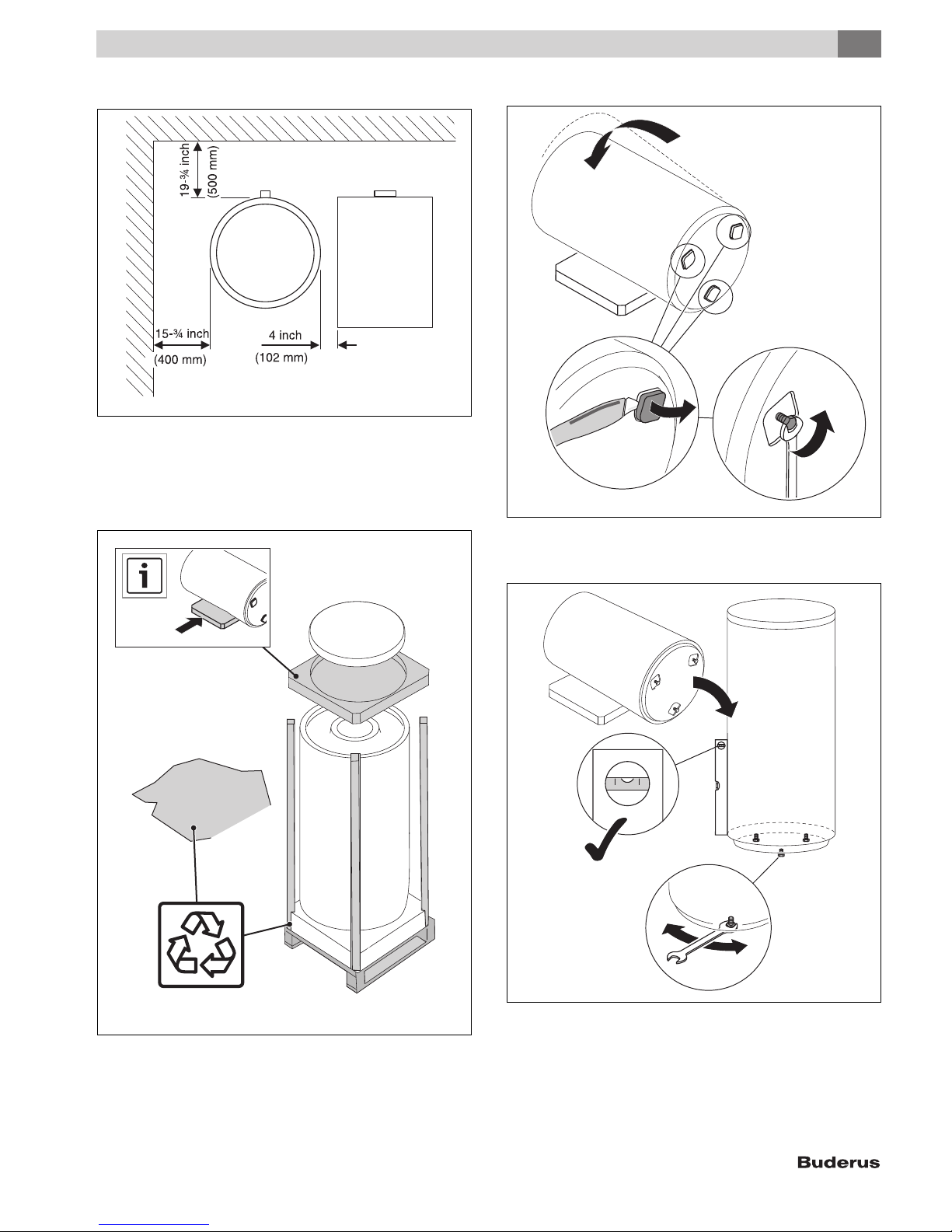
5.1.2 Wall clearances
6 720 801 769-03.1ITL
Fig. 6 Recommended minimum wall clearances
5.1.3 Positioning the tank
▶ Unpack the tank by removing the wrap, wooden boards and foam pad
on the top.
▶ Lay the foam pad on the floor to serve as a mat.
▶ Unscrew the adjustable feet [3].
1.
2.
3.
6 720 801 769-15.1ITL
Fig. 8 Lay down the DHW tank and expose the adjustable feet
▶ Position the DHW tank on a level floor with adequate load-bearing
capacity.
Fig. 7 Unpacking the DHW tank
▶ Carefully place the DHW tank on the cover pad [1].
▶ Cut out the raised sections in the EPS bottom pad [2].
SU54.5 | SU80.5 | SU100.5 – 6 720 819 292 (2017/11) 9
6 720 800 035-04.1ITL
6 720 801 769-13.1ITL
Fig. 9 Positioning the tank
▶ Maintain minimum wall clearances.
▶ Adjust the adjustable feet so that the DHW tank is vertical.
5
Installation
▶ Remove the caps from the connections.
A
B
NOTICE: Risk of corrosion from damage to the enamel
coating!
▶ Attach connections to the DHW tank only "hand-
tight".
5.2.1 Connecting the tank on the water side
System example with all recommended valves and shut-offs
( Fig. 11).
▶ When sizing the heating system expansion vessel, take the volume
of the heating coil in the tank into consideration.
▶ Route the connection cables for the tank temperature sensors at the
back of the tank through the insulation to the heating appliance or
controller.
▶ Install piping runs so that natural circulation is prevented.
If necessary, install check valves.
▶ Install connection cables free of stress.
▶ Attach piping to the tank connections on-site.
▶ Check all connections for leaks.
AW
6 720 800 155-22.1ITL
Fig. 10 Remove the caps
▶ Use Teflon tape or Teflon cord to seal the connections. Do not use
hemp to seal the connections.
5.2 Water connections
DANGER: Risk of injury from contaminated water!
Work carried out without due care for cleanliness
contaminates the drinking water.
▶ Install in accordance with national standards and
guidelines.
WARNING: Risk of fire from soldering and brazing!
▶ Take appropriate safety measures when soldering
and brazing as the thermal insulation is flammable.
For example, cover up the thermal insulation.
▶ Check tank jacket for damage after completing work.
NOTICE: Water damage!
▶ Connect the drain to the bottom tank connection prior
to filling the tank.
▶ Seal off all unused tank connections.
5
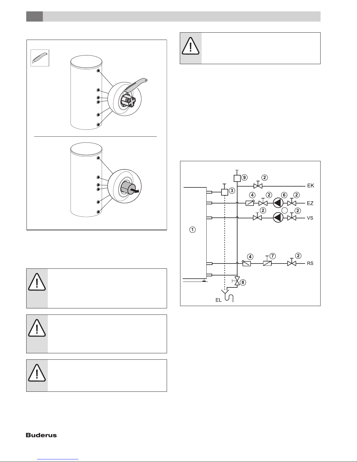
6 720 800 138-05.1ITL
Fig. 11 Installation (illustrative)
[1] Storage tank
[2] Shutoff valve
[3] P&T safety valve (combined with hot water outlet)
[4] Check valve
[5] Tank primary pump
[6] Recirculation pump (optional)
[7] Air eliminator (in main supply)
[8] Drain valve
[9] Expansion vessel
[AW] DHW outlet
[EK] Cold water inlet
[EL] Tank drain
[EZ] Recirculation inlet
[RS] DHW tank return
[VS] DHW tank supply
SU54.5 | SU80.5 | SU100.5 – 6 720 819 292 (2017/11)10
5.2.2 Installing a T&P safety valve (on-site)
▶ Install a listed T&P safety valve that is approved for drinking water
(¾ ") in the DHW outlet.
▶ This DHW tank must be installed with a new T&P safety valve.
▶ The T&P valve must be sized no smaller than the rated tank capacity.
▶ Observe the safety valve installation instructions.
▶ T&P discharge pipe:
– The blow-off line must be at least equal to the outlet cross-section
of the safety valve.
– Route the blow-off line from the T&P valve directly to an adequate
drain (maximum length 6 ft (2 m) with no more than two 90°elbows).
– The discharge line must terminate at an adequate drain in order to
prevent property damage from spillage.
– Check that the T&P safety valve operates properly at least once
annually.
▶ Never plug the blow-off line. During heating, water may be discharged
for operational reasons at any time.
5.3 Install a tank water temperature sensor (accessory)
or aquastat (accessory).
DANGER: Risk of fatal injury from electric shock.
▶ Isolate the system electrically prior to commencing
work on the system.
Connect the electrical power and set the temperature on
the DHW temperature sensor or the aquastat as shown in
the respective aquastat or control manufacturer's
instructions.
Install a tank temperature sensor or an aquastat on the DHW tank to
measure and monitor the hot water temperature.
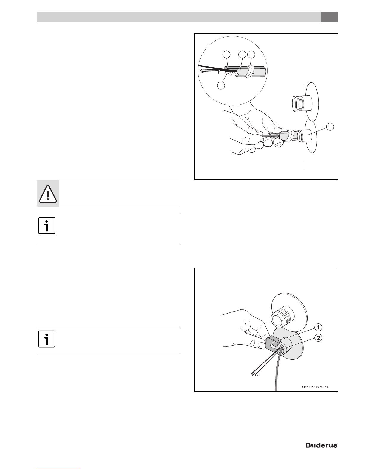
Installing the DHW temperature sensor
▶ Take the tank temperature sensor from the scope of delivery of the
control panel (accessories).
▶ Insert the sensor set until it bottoms out inside the sensor well [5].
This automatically pushes back the plastic spiral [3] that holds the
sensor set together.
The compensating spring [4] ensures contact between the sensor well
and sensor surfaces, and a reliable temperature reading.
Installation
5
123
4
5
6 720 800 155-17.1ITL
Fig. 12 Installing the DHW temperature sensor
[1] Quarter-circle spacer
[2] Temperature sensor
[3] Plastic spiral
[4] Compensating spring
[5] Sensor Well
▶ Push sensor retaining clip [1] from the side onto sensor well [2].
▶ Route the sensor lead to the boiler or control panel and ensure the
cable is not strained. The piping may not touch any hot parts of the
boiler.
▶ When sensors are used without a compensating spring, fill the cavity
in the sensor well with a sufficient amount of thermal grease.
Always ensure that the full length of the sensor surface is
in contact with the sensor well.
SU54.5 | SU80.5 | SU100.5 – 6 720 819 292 (2017/11) 11
Fig. 13 Installing the sensor retainer
[1] Sensor retainer
[2] Sensor Well
5
Installation
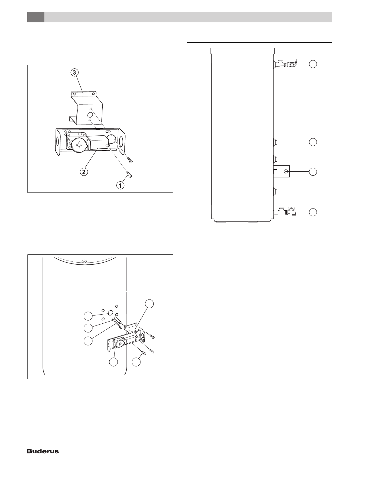
Installing the aquastat
▶ Remove cover from the aquastat. To do so, undo the screw on the top.
▶ If necessary, remove any unnecessary attachments. Screw on the
holder [3] to the Aquastat [2] using two sheet metal screws [1].
6 720 800 155-03.1ITL
Fig. 14 Screw the holder onto the Aquastat
[1] Self-tapping screws
[2] Aquastat
[3] Holder
▶ Feed the temperature sensor [4] with the compensating spring [3]
into the sensor well [5].
▶ Attach Aquastat [6] to tank by means of 4 sheet metal screws [1].
▶ Replace the cover of the aquastat [2].
Installing B-kit components
1
2
3
4
6 720 801 769-04.1ITL
Fig. 16 Installing B-kit components
[1] Tee 1" x 1" x ¾ " (2x) with P&T safety valve
[2] Cap¾ " for the recirculation connection
[3] Holder with Aquastat
[4] Tee with fill and drain valve
5
4
3
2 1
Fig. 15 Installing the aquastat
[1] Self-tapping screws
[2] Aquastat
[3] Compensating spring
[4] Temperature sensor
[5] Sensor Well
[6] Holder
6
6 720 800 155-04.1ITL
SU54.5 | SU80.5 | SU100.5 – 6 720 819 292 (2017/11)12
6 Start-up procedure
NOTICE: Risk of equipment damage from excess
pressure!
Excessive pressure can result in tension cracks in the
enamel coating.
▶ Never plug the blow-off line of the T&P safety valve.
6.1 Commissioning the DHW tank
Have the installer of the heating system or a qualified contractor
commission the equipment.
▶ Commission the boiler and additional accessories in accordance with
manufacturer's instructions or the appropriate installation and
operating instructions.
Use only drinking water to check the DHW tank for leaks.
On the DHW side, the test pressure must not exceed
150 psi (10,3 bar) gauge pressure.
▶ To bleed air from the DHW tank, open the highest tap/valve.
▶ To fill the tank, open the shut-off valve for the cold water inlet.
▶ Flush the tank and piping thoroughly prior to commissioning.
▶ Before heating up, verify that the boiler, tank and pipework are filled
with water. Open the air bleeder valve for this purpose.
▶ Check all connections, piping and the inspection port for leaks.
7 Shutdown
Start-up procedure
6
7.2 Shutting down the heating system when there is a risk
of frost
▶ Shut down the heating system and the DHW tank as shown in
Chapter 7.1.
Fully drain the tank – even the lowest section of the tank
and the heating coil.
8 Environmental protection/disposal
Environmental protection is one of the fundamental company policies of
the Bosch Group. We regard quality of performance, economy and
environmental protection as equal objectives.
Environmental protection laws and regulations are strictly adhered to.
To protect the environment, we use the best possible technology and
materials taking into account economic points of view.
Packaging
For the packaging, we participate in the country-specific recycling
systems, which guarantee optimal recycling. All packaging materials
used are environmentally-friendly and recyclable.
Old electrical and electronic appliances
Electronic or electrical or electronic equipment hat can no
longer be used must be collected separately and properly
recycled (European Directive on Waste: Electrical and
Electronic Equipment).
Use the return and collection systems specified by federal
law to dispose of electrical and electronic waste.
NOTICE: Risk of tank damage!
Residual moisture can result in corrosion.
▶ Thoroughly dry out the inside (e. g. by means of hot
air) and leave the cleanout cover open.
7.1 Shutting down the tank
▶ Switch off the temperature controller at the control panel, shut of the
heating system emergency shutoff switch, or disengage the heating
system circuit breaker.
WARNING: Risk of scalding from hot water!
▶ Let the tank cool down sufficiently.
▶ Close the cold water inlet shutoff valve.
▶ Drain the DHW tank via the drain valve by opening the highest faucet.
▶ Close the shut-off valves to and from the boiler.
▶ Depressurize the heat exchanger.
▶ Drain and blow out the heat exchanger.
▶ To prevent corrosion, dry out the inner space and keep the inspection
port covers open.
9 Maintenance
▶ Allow the DHW tank to cool down sufficiently before performing any
maintenance.
▶ Remedy all faults immediately.
▶ Use original spare parts only!
▶ The tank must be inspected annually and maintained as required.
▶ Check the T&P safety valve annually.
9.1 Preparing the DHW tank for cleaning
The SU80/5 and SU100/5 tanks are cleaned by means of the cleanout
on the side. The SU54/5 tank is cleaned by means of the cleanout at the
top.
WARNING: Risk of scalding from hot water!
▶ Prior to cleaning, allow the DHW tank to cool down
sufficiently.
▶ Disconnect electrical power from the heating system.
▶ Drain the DHW tank. To do so, close the shut-off valve for cold water
inlet and the open drain valve. To vent the system, open the air vent
valve or the highest faucet.
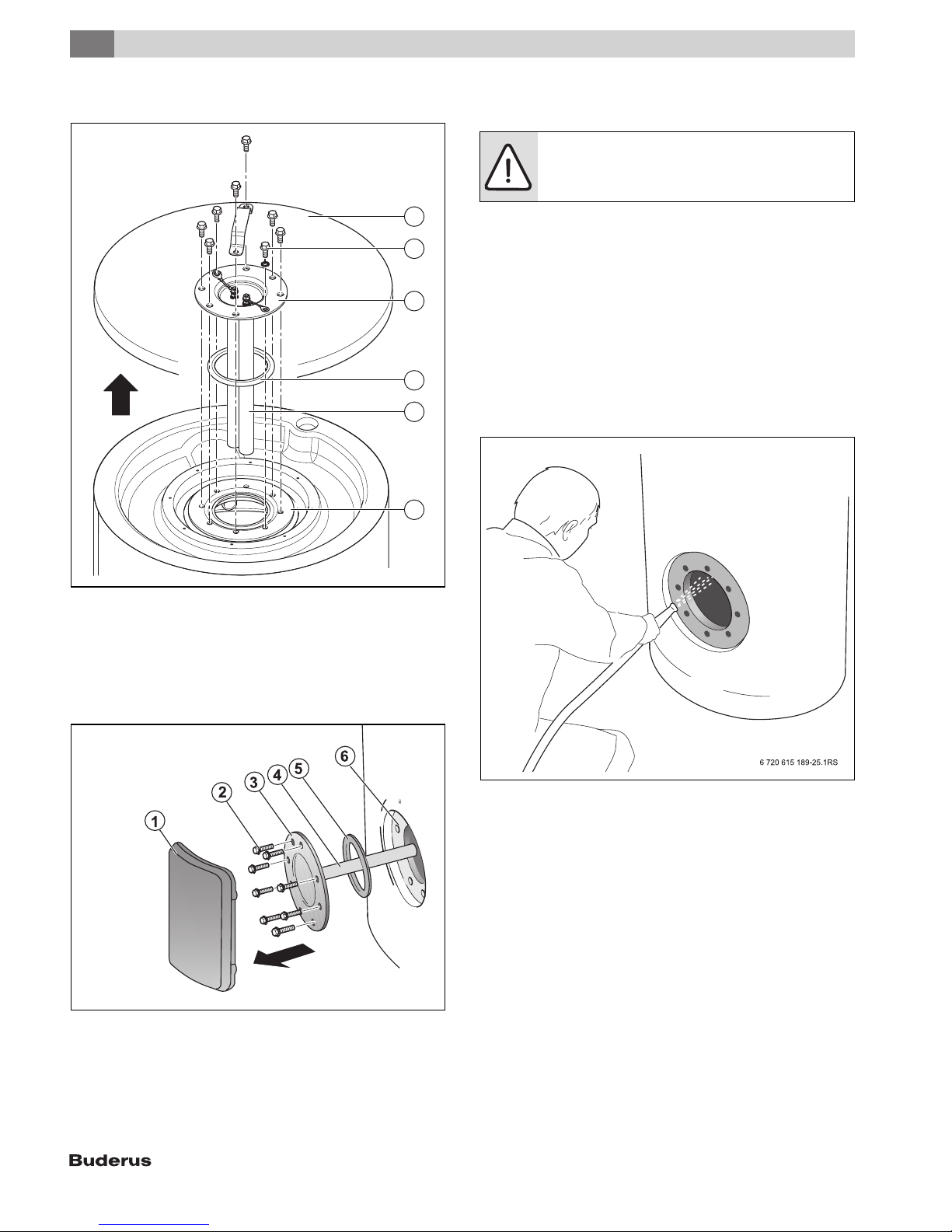
▶ PS jacket cover (SU54/5) ( Fig. 17, page 14, [1]) or handhole
cover (SU80/5, SU100/5) ( Fig. 18, page 14, [1]) of the DHW
tank.
▶ Loosen the hex bolts [2] in the cleanout cover [3].
SU54.5 | SU80.5 | SU100.5 – 6 720 819 292 (2017/11) 13
9
Maintenance
▶ Remove the handhole cover [3], magnesium anode [5] and handhole
cover seal [4].
1
2
3
4
5
6
9.2 Descaling/cleaning the tank
▶ Check the DHW tank interior for scale deposits (calcium).
NOTICE: Risk of tank damage due to damaged enamel.
▶ Never use hard objects or tools with sharp edges to
clean the interior of the tank
Should limescale be discovered inside the DHW tank, proceed as
follows:
▶ Hose down the inside of the DHW tank with a “high-pressure” (approx.
58 – 72.5 psi (4 - 5 bar) gauge pressure) cold water jet.
You can increase the cleaning effect by heating up the heat exchanger
in the drained tank before cleaning. The thermal shock effect releases
scale deposits more easily from the coil-type heat exchanger.
▶ Use a wet & dry vacuum cleaner with plastic suction hose to remove
the residues.
Should thick limescale be discovered inside the DHW tank, it can be
removed chemically. We recommend that you have a qualified
contractor carry out the chemical cleaning operation.
6 720 801 769-07.1ITL
Fig. 17 Removing the cleanout cover SU54/5
[1] PS top cover
[2] Hex bolts
[3] Handhole cover
[4] Handhole cover gasket
[5] Magnesium anodes
[6] Inspection port
Fig. 18 Removing the cleanout cover SU80/5, SU100/5
[1] Cleanout cover shroud
[2] Hex bolts
[3] Handhole cover
[4] Magnesium anode
[5] Handhole cover gasket
[6] Inspection port
Fig. 19 Hose down the inside of the tank as shown in the example
SU80/5, SU100/5
6 720 805 397-09.1ITL
SU54.5 | SU80.5 | SU100.5 – 6 720 819 292 (2017/11)14
Maintenance
9
9.3 Checking the magnesium anode
If the magnesium anode is not serviced properly, the
warranty is void.
Annual service records must be kept in a safe location
and submitted together with the original purchase
receipt in the event of a warranty claim.
The magnesium anode protects the DHW tank from corrosion. Check the
magnesium anode annually to determine whether it needs to be
changed.
The surface of the magnesium anode must be free of deposits. Exchange
the magnesium anode when deposits collect, the surface is enlarged
from deposits, or the diameter is less than 5/8" (15 mm).
Certain installations may require more frequent replacement of the
magnesium anode rod:
• Recirculation connection
• Poor water quality
• Galvanic/electrolytic corrosion
• High flow rate
In the event of poor water quality it is recommended that a water
treatment professional be consulted for water treatment options.
Never bring the magnesium anode surface in contact
with oil or grease.
▶ Keep everything clean.
9.3.2 Check the top magnesium anode (SU54/5)
▶ Remove the cleanout cover ( Fig. 17, page 14), if not yet removed.
▶ Check the magnesium anodes.
▶ If the diameter has decreased to about 5/8 " (15 mm), exchange the
magnesium anode.
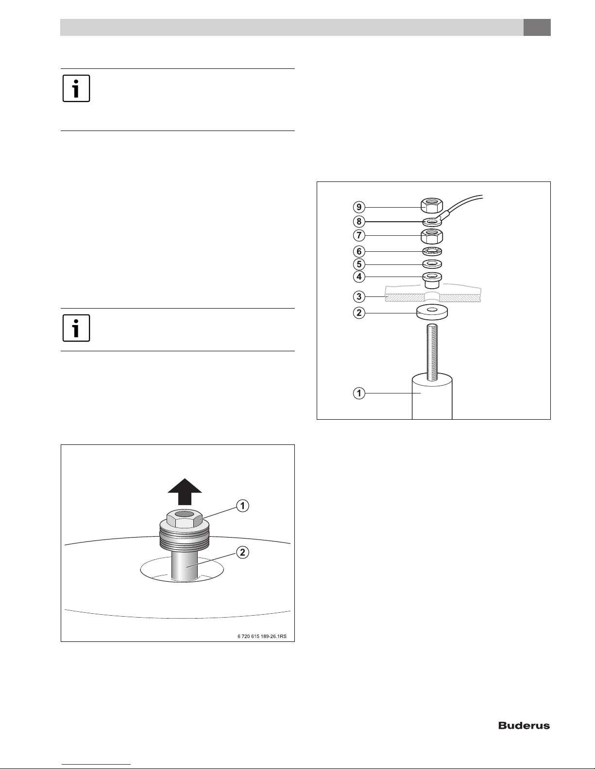
▶ Unscrew the nut M8 [9] to release the eyelet of the grounding cable
connecting lead[8].
▶ Unscrew the M8 nut [7].
▶ Remove the handhole cover [3] from the magnesium anode [1].
▶ Install the new magnesium anode with the provided small parts
( Fig. 21).
9.3.1 Check the top magnesium anode (SU80/5, SU100/5)
▶ Remove PS top cover if not already removed.
▶ Unscrew the magnesium anodes.
▶ Check the magnesium anodes for decomposition.
▶ If the diameter has decreased to about 5/8 " (15 mm), exchange the
magnesium anode.
▶ Screw the magnesium anodes back into the sleeve.
Fig. 20 Check the top magnesium anode (SU80/5, SU100/5)
[1] Hex bolt
[2] Magnesium anode
Fig. 21 Replacing the magnesium anode
[1] Magnesium anode
[2] Gasket
[3] Handhole cover
[4] Insulating sleeve
[5] U-washer
[6] Serrated washer
[7] M8 Nut
[8] Eyelet of the grounding cable connecting lead
[9] M8 Nut
9.3.3 Check the side magnesium anode
(SU80/5, SU100/5)
▶ Empty the tank as described in chapter 9.1, page 13.
▶ Remove the cleanout cover ( Fig. 17, page 14), if not yet removed.
▶ Check the magnesium anodes.
▶ If the diameter has decreased to about ½ " (15 mm), exchange the
magnesium anode.
▶ Unscrew the nut M8 [9] to release the eyelet of the grounding cable
connecting lead[8].
▶ Unscrew the M8 nut [7].
▶ Remove the handhole cover [3] from the magnesium anode [1].
▶ Install the new magnesium anode with the provided small parts
( Fig. 21).
SU54.5 | SU80.5 | SU100.5 – 6 720 819 292 (2017/11) 15
9
Maintenance
9.4 Startup after maintenance
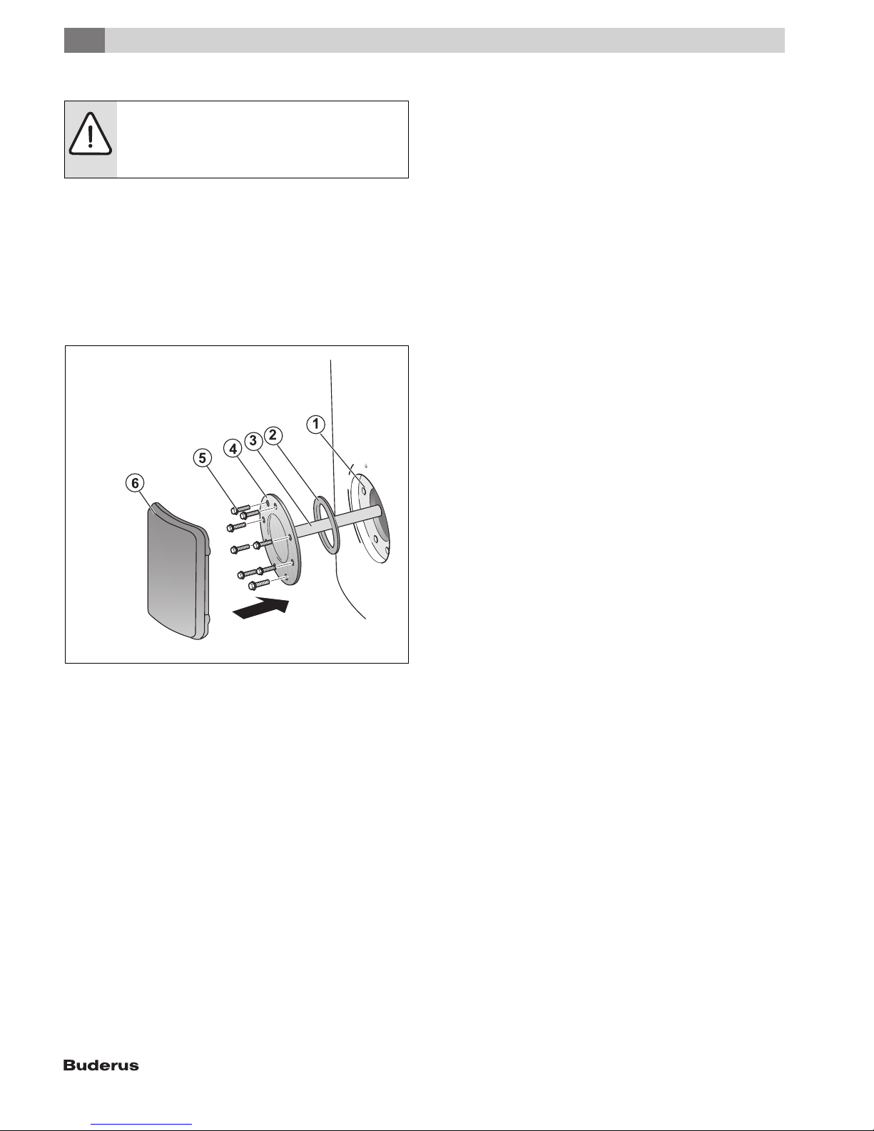
NOTICE: Risk of tank damage from a faulty gasket!
▶ To prevent the DHW tank from leaking, install a new
cleanout cover gasket upon completion of cleaning
and maintenance.
▶ Put the cleanout cover [4] back in place (top or side) together with the
new gasket [2].
▶ Thread hex bolts [5] into cleanout cover [4] "hand-tight".
▶ Then use a torque wrench to tighten the hex bolts to 18-22 lbf-ft
(25 - 30 Nm).
▶ Fill the DHW tank and restart the heating system.
▶ Check all connections and the inspection port for leaks.
▶ Replace the cleanout cover shroud.
▶ Reposition the PS top cover on the tank.
Fig. 22 Reassembling the inspection port
[1] Inspection port
[2] Handhole cover gasket
[3] Magnesium anode
[4] Handhole cover
[5] Hex bolts
[6] Cleanout cover shroud
6720 800 155-06.1ITL
SU54.5 | SU80.5 | SU100.5 – 6 720 819 292 (2017/11)16
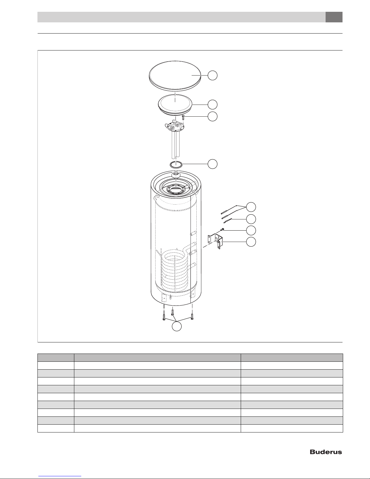
10 Spare Parts
Spare Parts
10
1
2
4
6
9
10
13
14
4
Fig. 23 Spare parts for SU54/5
Item Article description Product No.
1 Cover D550 lid, black 8 718 542 319 0
2 Plug, EPS upper part D370 8 718 541 763 0
4 Self-tapping hex screw M10x25 (8x) 7 747 005 744
6 O-ring 120.02x6.99-N 8 718 572 538 0
9 Spacer, 1/4-circle (1x) 8 718 585 547
10 Compensator spring (5x) 8 718 585 143
13 Self-tapping screw St 4.2x13 (10x) 7 747 027 696
14 Retaining plate for the aquastat 7 747 028 761 0
Logo Buderus 8 718 541 573 0
Table 7
6 720 805 397-18.1ITL
SU54.5 | SU80.5 | SU100.5 – 6 720 819 292 (2017/11) 17
10
Spare Parts
1
2
2
4
4
4
4
2
2
2
3
3
3
3
1
1
5
5
6
6
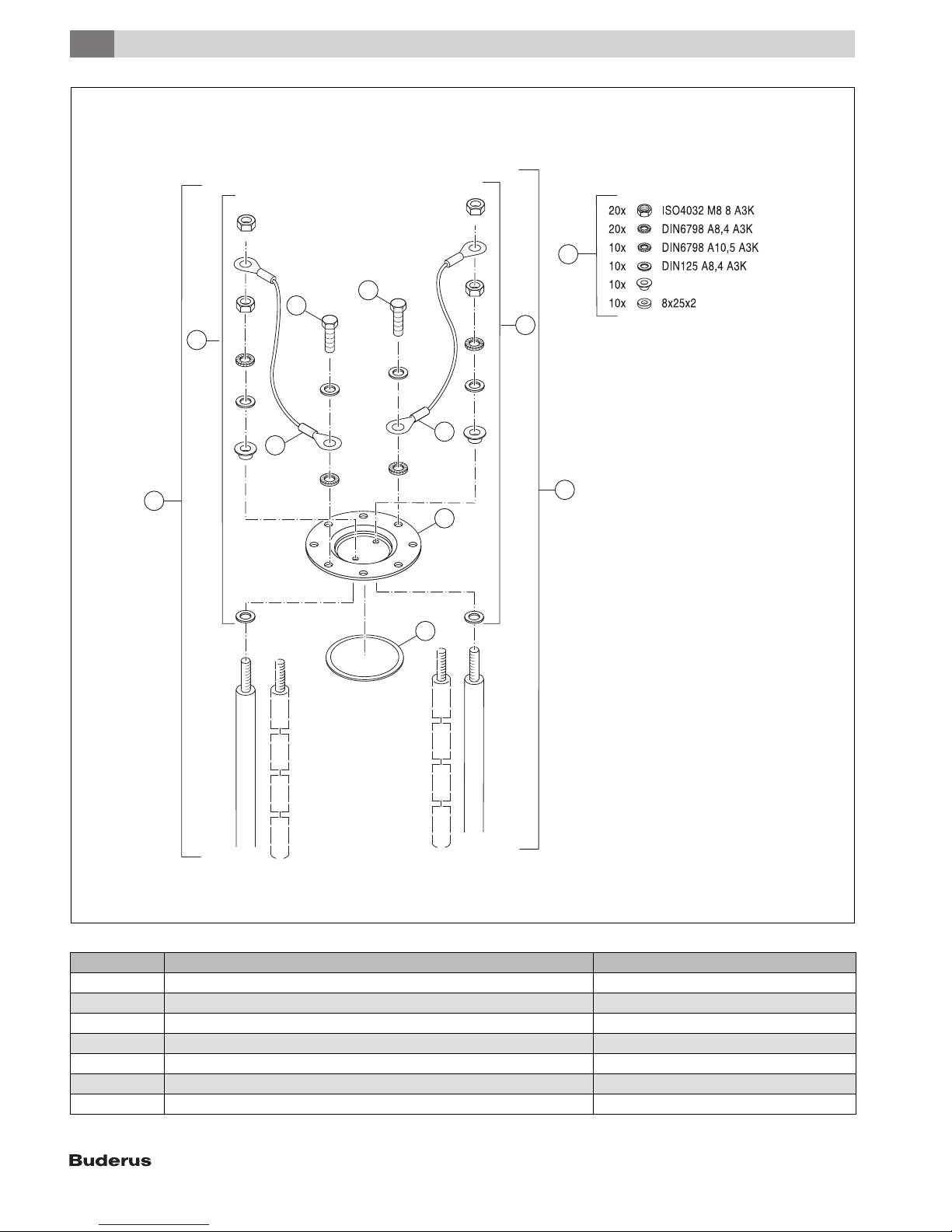
Fig. 24 Spare parts for SU54/5
Item Article description Product No.
1 Multi-link anode, 3 links 558/528mm M8 63020947
1 Anode D33x400mm (1x) 8 718 571 568 0
2 Anode mounting kit (10x) 5264278
3 Anode connecting lead (insulated) 63037168
4 Self-tapping hex screw M10x25 (8x) 7 747 005 744
5 Cleanout cover DN120 SA5, thermoplastic 8 718 543 791 0
6 O-ring 120.02x6.99-N 8 718 572 538 0
Table 8
6 720 805 397-19.1ITL
SU54.5 | SU80.5 | SU100.5 – 6 720 819 292 (2017/11)18
 Loading...