

Page 1
Solar and High-Performance
DHW Storage Tanks
WARNING:
These installation instructions are intended solely for use by a licensed
heating contractor or service technician. Read all instructions before installing. Perform steps exactly in the order given. Failure to follow these
instructions can result in severe injury, death or property damage.
NOTICE:
The heat transfer medium must be nontoxic water with Toxicity Class 1
as listed in "Clinical Toxicology of Commercial Products," 5th edition.
The heat transfer medium must be limited to a maximum pressure of
30 PSIG by an approved safety or pressure relief valve.
DANGER :
Cette notice d’installation doit être utilisée uniquement par des installateurs chauffagistes ou des techniciens de maintenance qualifiés. Lisez
attentivement toutes les consignes avant l’installation. Exécutez les actions précisément dans l’ordre indiqué. En cas de non-respect, vous risquez de subir de sérieuses blessures pouvant conduire à la mort ou
d’entraîner de lourds dommages matériels.
REMARQUE :
Le milieu caloporteur doit être de l’eau non toxique de classe 1 telle que
précisé dans la 5e édition de « Clinical Toxicology of Commercial
Products ». Le liquide caloporteur doit être limité à une pression maximale
de 30 PSIG par une soupape de sécurité ou de surpression homologuée.
PELIGRO :
Este manual de instalación únicamente lo pueden utilizar instaladores de
calefacción o técnicos especializados. Antes de la instalación, lea todas
las indicaciones. Realice todas las acciones exactamente en el orden indicado. En caso de incumplimiento, existe riesgo de lesiones graves e incluso de muerte o daños materiales considerables.
6 720 647 567-00.1ITL
AVISO :
El portador de calor se debe limitar a una presión máxima de 2 bar mediante una válvula de seguridad o de sobrepresión.
SM80/5, SM100/5
[en] Installation and Service Instructions - Read carefully prior to installation and maintenance.. . . . . . . . . . . . . . . . . . . . . . . . . . . . . 2
[fr] Notice d’installation et d’entretien - À lire attentivement avant le montage et la maintenance. . . . . . . . . . . . . . . . . . . . . . . . . . . . 19
[es] Instrucciones de mantenimiento y de instalación -
Léase atentamente antes del montaje o de la realización de trabajos de mantenimiento. . . . . . . . . . . . . . . . . . . . . . . . . . . . . . . . 37
6 720 800 156 (2017/07) US/CA/MX
Page 2
Contents
Contents
1 Safety Considerations and Symbol Descriptions . . . . . . . . . . 3
1.1 Explanation of symbols . . . . . . . . . . . . . . . . . . . . . . . . . . 3
1.2 Safety instructions . . . . . . . . . . . . . . . . . . . . . . . . . . . . . . 3
1.3 Instructions for the owner and operator . . . . . . . . . . . . . 4
2 Product Information . . . . . . . . . . . . . . . . . . . . . . . . . . . . . . . . . . . 4
2.1 Scope of delivery . . . . . . . . . . . . . . . . . . . . . . . . . . . . . . . 4
2.2 Designated use . . . . . . . . . . . . . . . . . . . . . . . . . . . . . . . . . 5
2.3 Product Information . . . . . . . . . . . . . . . . . . . . . . . . . . . . . 5
2.4 Data plate . . . . . . . . . . . . . . . . . . . . . . . . . . . . . . . . . . . . . 5
2.5 Pressure drop curve of heating coil . . . . . . . . . . . . . . . . . 6
2.6 Technical Data . . . . . . . . . . . . . . . . . . . . . . . . . . . . . . . . . 7
2.7 Physical and connection dimensions . . . . . . . . . . . . . . . 8
3 Standards, regulations and directives . . . . . . . . . . . . . . . . . . . 9
4 Moving the tank . . . . . . . . . . . . . . . . . . . . . . . . . . . . . . . . . . . . . . 9
5 Installation . . . . . . . . . . . . . . . . . . . . . . . . . . . . . . . . . . . . . . . . . . . 9
5.1 Tank installation . . . . . . . . . . . . . . . . . . . . . . . . . . . . . . . . 9
5.1.1 Requirements for installation location . . . . . . . . . . . . . . 9
5.1.2 Wall clearances . . . . . . . . . . . . . . . . . . . . . . . . . . . . . . . . 10
5.1.3 Positioning the tank . . . . . . . . . . . . . . . . . . . . . . . . . . . . 10
5.2 Water connections . . . . . . . . . . . . . . . . . . . . . . . . . . . . . 11
5.2.1 Connecting the tank on the water side . . . . . . . . . . . . . 12
5.2.2 Installing a T&P safety valve (on-site) . . . . . . . . . . . . . . 12
5.3 Installing the DHW water temperature sensor
(accessory) or Aquastat (accessory) . . . . . . . . . . . . . . 12
5.4 Connecting the KS solar pump station . . . . . . . . . . . . . 14
5.5 Connection as high-performance DHW tank . . . . . . . . . 14
5.5.1 Series connection of the lower and upper heat
exchanger . . . . . . . . . . . . . . . . . . . . . . . . . . . . . . . . . . . 14
5.5.2 Parallel connection of the lower and upper heat
exchanger . . . . . . . . . . . . . . . . . . . . . . . . . . . . . . . . . . . . 15
9 Maintenance . . . . . . . . . . . . . . . . . . . . . . . . . . . . . . . . . . . . . . . 15
9.1 Preparing the DHW tank for cleaning . . . . . . . . . . . . . . 15
9.2 Descaling/cleaning the tank . . . . . . . . . . . . . . . . . . . . . 16
9.3 Check the magnesium anodes . . . . . . . . . . . . . . . . . . . . 16
9.4 Startup after maintenance . . . . . . . . . . . . . . . . . . . . . . . 17
10 Spare Parts . . . . . . . . . . . . . . . . . . . . . . . . . . . . . . . . . . . . . . . . . 18
10.1 Spare parts for SM80/5, SM100/5 . . . . . . . . . . . . . . . 18
6 Start-up procedure . . . . . . . . . . . . . . . . . . . . . . . . . . . . . . . . . . . 15
6.1 Commissioning the DHW tank . . . . . . . . . . . . . . . . . . . . 15
7 Shutdown . . . . . . . . . . . . . . . . . . . . . . . . . . . . . . . . . . . . . . . . . . . 15
7.1 Shutting down the tank . . . . . . . . . . . . . . . . . . . . . . . . . 15
7.2 Shutting down the heating system when there is a risk
of frost . . . . . . . . . . . . . . . . . . . . . . . . . . . . . . . . . . . . . . 15
8 Environmental protection/disposal . . . . . . . . . . . . . . . . . . . . . 15
SM80/5, SM100/5 – 6 720 800 156 (2017/07)2
Page 3
1 Safety Considerations and Symbol
Descriptions
1.1 Explanation of symbols
Safety Considerations and Symbol Descriptions
Installation and commissioning
▶ The electrical connection must be connected by a electrician.
The wiring diagram must be followed.
▶ Do not install this device in rooms with a high moisture level
(e.g. bathrooms, saunas).
1
Warnings
Warnings in this document are identified by a warning
triangle printed against a grey background.
Keywords at the start of a warning indicate the type and
seriousness of the ensuing risk if measures to prevent
the risk are not taken.
The following keywords are defined and can be used in this document:
• DANGER indicates a hazardous situation which, if not avoided, will
result in death or serious injury.
• WARNING indicates a hazardous situation which, if not avoided,
could result in death or serious injury.
• CAUTION indicates a hazardous situation which, if not avoided,
could result in minor to moderate injury.
• NOTICE is used to address practices not related to personal injury.
Important Information
This symbol indicates important information where
there is no risk to people or property. It is separated by
horizontal lines above and below the text.
Additional symbols
Symbol Function
▶ Sequence of steps
Cross-reference to another part of the document
• Listing/list entry
– Listing/list entry (2nd level)
Table 1
1.2 Safety instructions
Read all instructions before installing. Perform the steps in the indicated
sequence. Have the DHW tank inspected by a trained service technician
at least once every year. Failure to comply with these instructions can
result in severe, possibly fatal, personal injury as well as damage to
property and equipment.
Installation and servicing
▶ Risk of fire from soldering and brazing!
Take appropriate protective measures when soldering and brazing as
the insulation is flammable, for example, cover the insulation.
▶ Ensure that only a licensed contractor installs or services the DHW
tank.
▶ Use installation material with adequate temperature stability.
Function
▶ To ensure that the tank functions properly, heed these installation
and maintenance instructions.
▶ Never close the blow-off line of the T&P safety valve. For safety
reasons, water may escape during heating.
Danger from electric shock
▶ Make sure that only certified electricians perform the electrical work.
▶ Before performing electrical work, disconnect the power and secure
the unit against unintentional reconnection.
▶ Ensure the system has been disconnected from the power supply.
Risk of scalding at the hot water draw-off point
▶ When the DHW tank is in operation, temperatures in excess of 122 °F
(50 °C) can occur. To limit the temperature at the tap, install a
thermostatic DHW mixing valve.
▶ Water heated for washing the laundry, dishes and for other cleaning
purposes can cause scalding and permanent injuries.
▶ Children, elderly, and handicapped persons are more likely to be
permanently injured by hot water. Never leave such individuals in the
tub or shower unattended under any circumstances. Children must
not be allowed to operate hot water faucets themselves or to fill a
bathtub.
▶ If the building has occupants in the above groups who operate hot
water faucets, or state laws / local ordinances stipulate specific
water temperatures, take the following precautions:
– Use the lowest possible temperature setting.
– To prevent scalding, install a tempering device, such as an
automatic mixing valve, at hot water tap or water heater. Select
and install the automatic mixing valve in accordance with the
valve manufacturer's recommendations and instructions.
▶ Water exiting from drain valves can be extremely hot. To avoid
injuries:
– Check that all connections are tight.
– Direct exiting water away from people.
▶ Measures must be taken to protect against excessive temperature
and pressure! Installation of a T&P safety valve is required.
The chart below shows the relationship between water temperature and
time until there is a risk of scalding. It can be used as the basis for
determining the safest water temperature for your application.
Forbidden:
Connection of the potentiostat for an impressed current anode to the
magnesium anode installed in a storage tank is absolutely forbidden!
This would destroy the tank! The warranty would be voided.
SM80/5, SM100/5 – 6 720 800 156 (2017/07) 3
Page 4
2
Product Information
Temperature Time to severe scalding
120 °F (48 °C) longer than 5 minutes
125 °F (51 °C) 1.5 to 2 minutes
130 °F (54 °C) approx. 30 seconds
135 °F (57 °C) approx. 10 seconds
140 °F (60 °C) less than 5 seconds
145 °F (62 °C) less than 3 seconds
150 °F (65 °C) approx. 1.5 seconds
155 °F (68 °C) approx. 1 second
Table 2 Approximate time-temperature relationship until there is a risk
of scalding
1. Source: Moritz, A.R. and Henriques, F.C., Jr. (1947). Studies of thermal injury.
II. The relative importance of time and surface temperature in the causation of
cutaneous burns, Am J of Pathol, 23, 695-720.
To protect against corrosion and ensure compliance with the rules for
electrical safety, observe the following points:
▶ Use metal fittings for drinking water heating systems with plastic
piping.
▶ Use only original accessories from the manufacturer.
▶ When installation of the tank is complete, inspect the ground
conductor (including metal fittings).
Maintenance
Customers are advised to:
▶ Sign a maintenance and inspection contract with an authorized
contractor. Inspect and maintain the DHW tank as necessary on a
yearly basis. Service as needed.
▶ Use only original spare parts.
Flooding
▶ After a flood, do not use the appliance if any part has been
submerged. Damage to appliances that have been submerged can be
quite severe and pose numerous safety risks.
▶ An appliance that was subject to flooding must be replaced.
1
1.3 Instructions for the owner and operator
WARNING: Risk of scalding at the taps!
There is a risk of scalding at the taps if the tank
temperature is set above 122 °F (50 °C) and during
thermal disinfection.
▶ Advise users that they should draw off only mixed
water. Otherwise, install a thermostatic DHW mixing
valve.
▶ Highlight the following for the user:
– Water may be discharged from the T&P safety valve during heat-
up.
– The blow-off line on the T&P safety valve must always be kept
open.
– Check that the T&P safety valve operates properly at least once
yearly.
– The tank must be inspected annually and maintained as required.
2 Product Information
2.1 Scope of delivery
• DHW tanks
•Tank components
• Installation and Maintenance Instructions
3
1
2
4
5
6
7
6 720 805 397-01.1ITL
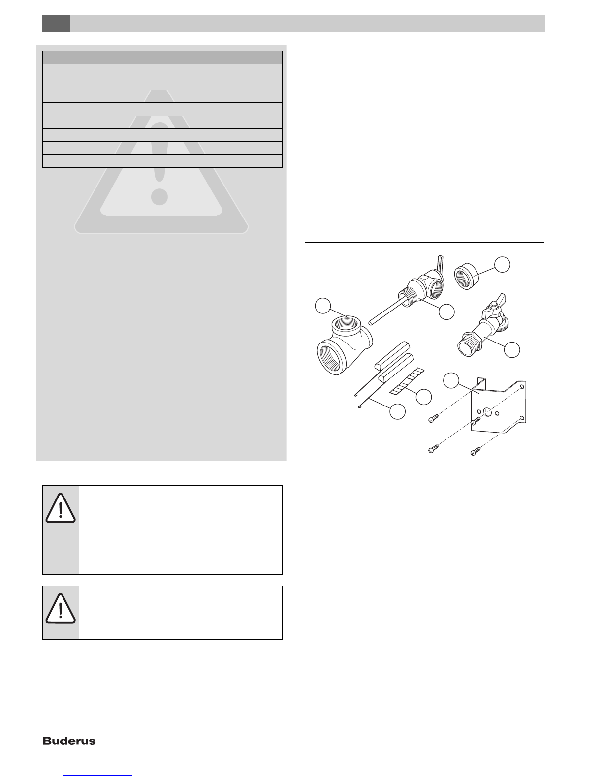
Fig. 1 Tank components
[1] Tee 1" x 1" x 3/4" (2x)
[2] Temperature and pressure relief valve
[3] Recirculation connection cap 3/4"
[4] Drain valve
[5] Bracket for aquastat, screws for aquastat bracket (4x)
[6] Com pensating spring for aquastat or cylinder temperature sens or
[7] Quarter-circle spacers for aquastat or tank temperature sensor
(2x)
NOTICE: Risk of tank damage from excessively high
pressure.
▶ Never close the temperature and pressure safety
valve blow-off line.
▶ Explain the operation and handling of the heating system and DHW
tank, making a particular point of safety-relevant features.
▶ Explain the function and how to check the T&P safety valve.
▶ Hand all enclosed documents over to the owner/operator.
▶ Recommendation for the user: Sign a maintenance and inspection
contract with a licensed contractor.
SM80/5, SM100/5 – 6 720 800 156 (2017/07)4
Page 5
2.2 Designated use
The DHW tank can be operated in a solar thermal system with a boiler as
a back-up, or for high output only with a boiler. (Operation of the two
heat exchangers in series or parallel.) The tank is designed for heating
and storing drinking water. Please observe national, regional, and local
codes, regulations, guidelines and standards for drinking water. When
operated as part of a solar system, the solar thermal system must be
filled with solar antifreeze to prevent frost damage.
The tank can be used only in closed loop systems and is not suitable for
drain-back solar thermal systems. Any other purpose is considered
improper use. Any resulting damage is excluded from the
manufacturer's warranty.
Requirements
for potable water Unit
Water hardness, min. ppm
grain/US gallon
°dH
36
2.1
2
pH value, min. – max. 6.5 – 9.5
Conductivity, min. – max. μS/cm 130 – 1500
Table 3 Requirements for potable water
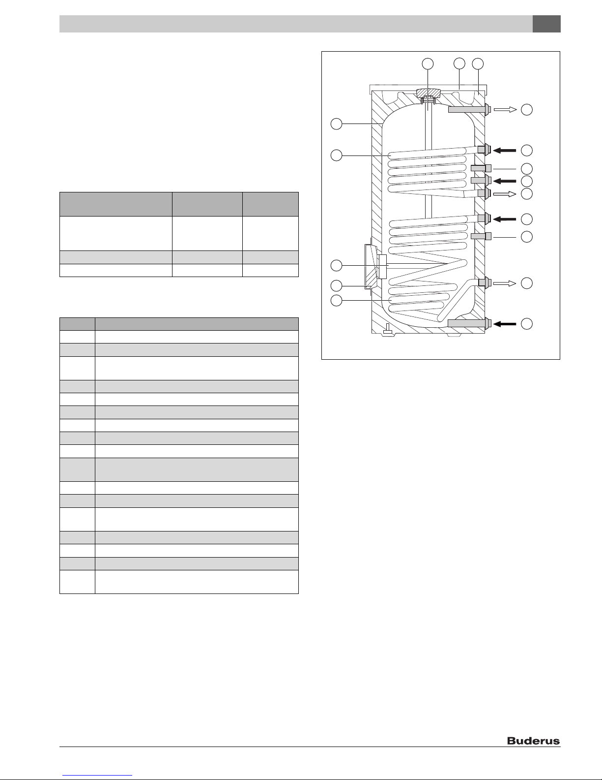
2.3 Product Information
14
13
12
11
10
Product Information
16
15
17
2
1
2
3
4
5
6
7
8
Item Description
1 DHW outlet
2 Boiler supply
3 Sensor well for temperature sensor, heat source or
aquastat
4 Recirculation connection
5 Boiler return
6 Solar supply
7 Sensor well for temperature sensor, solar
8 Solar return
9 Cold water inlet
10 Bottom heat exchanger for heating by a solar system,
smooth enameled tubing
11 Inspection port for service and cleaning at the front
12 Fitted magnesium anode without electrical insulation
13 Upper heat exchanger for reheating by heating appliance,
smooth enameled tubing
14 Tank, enameled steel
15 Fitted magnesium anode without electrical insulation
16 PS top cover
17 Jacket, painted sheet metal with rigid polyurethane foam
insulation, 2" (50 mm)
Table 4 Product Information
9
6 720 800 155-01.1ITL
Fig. 2 SM80/5, SM100/5
2.4 Data plate
The data plate is located at the top rear of the DHW tank.
SM80/5, SM100/5 – 6 720 800 156 (2017/07) 5
Page 6
2
feed of head
feed of head
Product Information
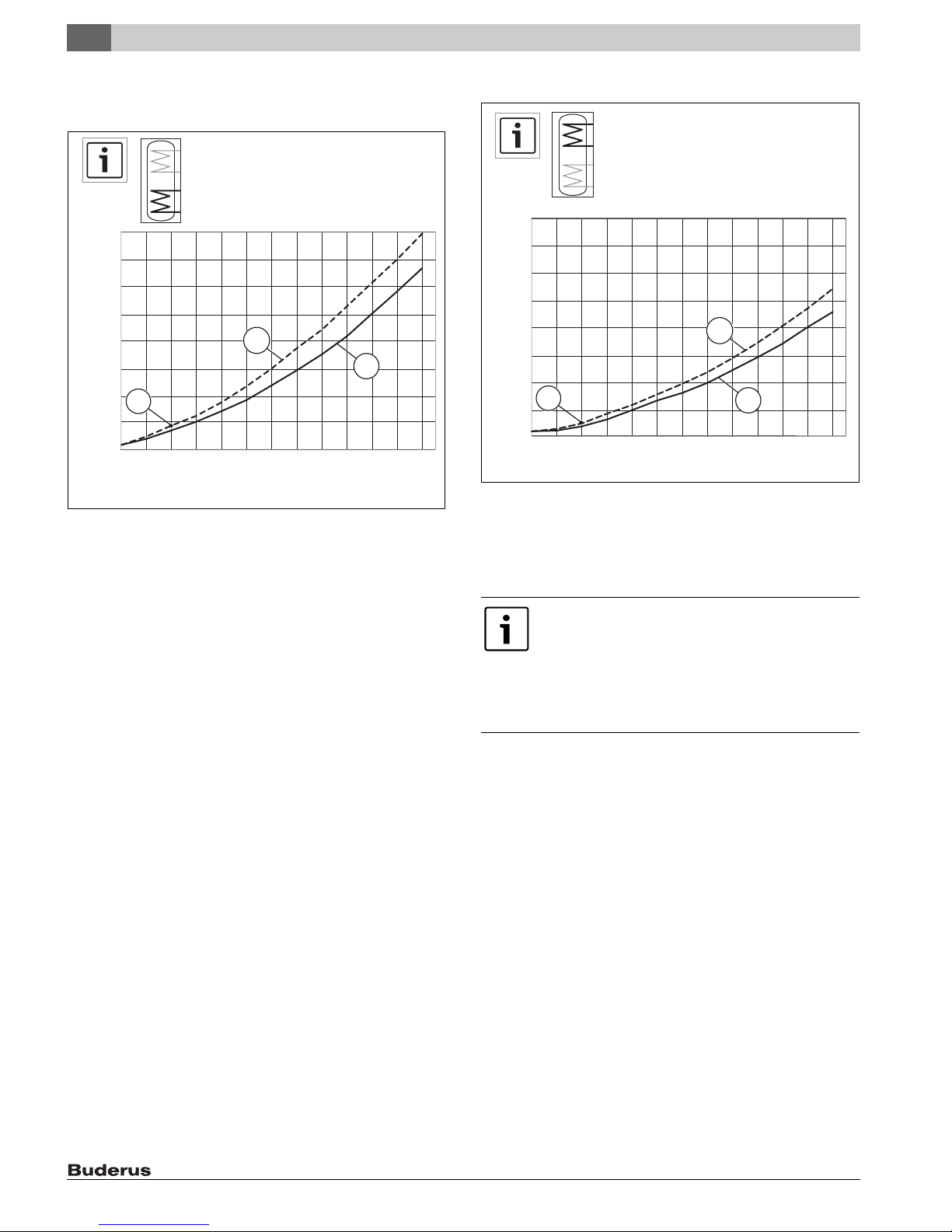
2.5 Pressure drop curve of heating coil
Pressure drop curve of bottom heat exchanger
20.00
15.00
10.00
feed of head
5.00
A
0.00
4.00 6.00 8.00 10.00 12.00 14.00 16. 00
2
18.00
20.00 22.00 24.00
gpm
Fig. 3 Pressure drop curve of bottom heat exchanger
[1] SM80/5
[2] SM100/5
Example:
[A] 8 gpm, 2.2feed of head
1
26.00 28.00
6 720 800 155-18.2T
Pressure drop curve of top heat exchanger
20.00
15.00
10.00
feed of head
5.00
2
B
0.00
4.00 6.00 8.00 10.00 12.00 14.00 16.00
Fig. 4 Pressure drop curve of top heat exchanger
[1] SM80/5
[2] SM100/5
Example:
[B] 8 gpm, 1.4 feed of head
If the two heat exchangers are piped in series, the
pressure drops are cumulative.
If they are operated in parallel, a separate pump is
recommended for each heat exchanger. Otherwise, fl ow
setters are needed to regulate the flow through the two
heat exchangers.
Ensure that in any case the pumps meet the load.
gpm
18.00
20.00 22.00 24.00
1
26.00 28.00
6 720 800 155-19.2T
SM80/5, SM100/5 – 6 720 800 156 (2017/07)6
Page 7
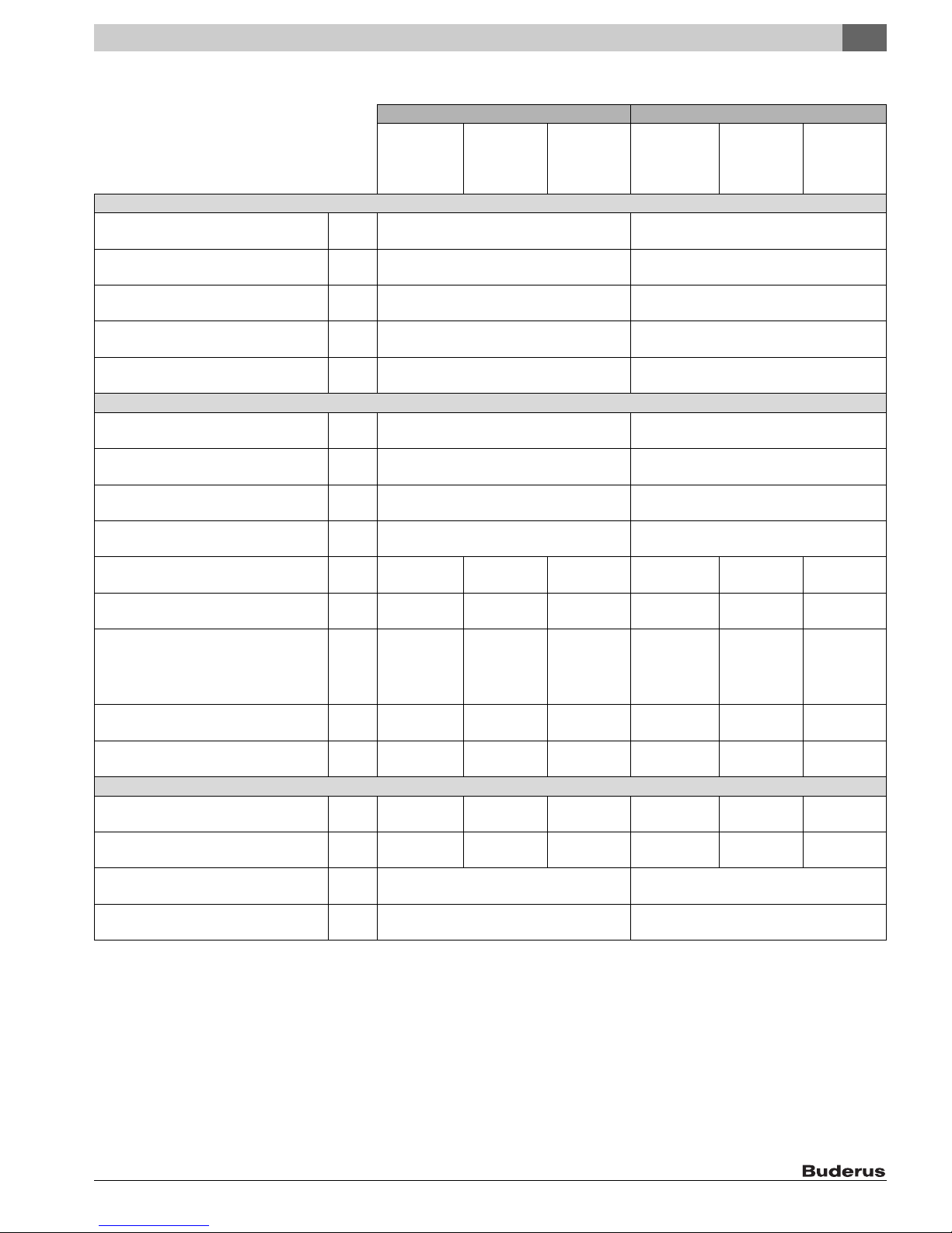
2.6 Technical Data
Tank capacity
Available capacity (total) gal
(l)
Maximum flow rate gpm
(l/min)
Maximum permissible DHW temperature °F
(°C)
Maximum permissible DHW operating pressure psi
(bar)
Stand-by heat loss (at 149 °F (65 °C) DHW
temperature, 68 °F (20 °C) room temperature)
Storage tank performance
Cold water inlet temperature °F
Domestic hot water outlet temperature °F
DHW temperature rise °F
Heat exchanger flow temperature °F
Heat exchanger flow rate gpm
Heat exchanger pressure drop f o h
Continuous rating gph
Amount that can be drawn off in the first hour gph
Maximum heat input btu/hr
Heat exchanger
Content gal
Surface area ft
Maximum heating water temperature °F
Max. operating pressure, heat exchanger psi
Table 5 Technical Data
°F/h
(K/h)
(°C)
(°C)
(°C)
(°C)
(l/h)
(mbar)
(l/h)
gpm
(l/min)
(l/h)
(kW)
(liter)
(m2)
(°C)
(bar)
2
Lower heat
exchanger
connected to
boiler
11.4
(2600)
2.5
(74)
185
(700)
3.1
(12)
257
(973)
112 398
(33)
2.3
(8.7)
13.99
(1.3)
Product Information
SM80/5 SM100/5
Upper heat
exchanger
connected to
boiler
75.4
(285)
7.5
(28)
203
(95)
150
(10.3)
0.6
(0.34)
50
(10)
140
(60)
90
(50)
176
(80)
11.4
(2600)
1.8
(53)
135
(510)
2.2
(9)
135
(510)
78 187
(22.9)
1.6
(6.1)
9.69
(0.9)
230
(110)
232
(16)
Both heat
exchangers in
series with the
boiler
11.4
(2600)
3.2
(95)
298
(1128)
5.0
(19)
362
(1370)
178 797
(52.4)
3.8
(14.4)
23.68
(2.2)
Lower heat
exchanger
connected to
boiler
14
(3180)
5.8
(175)
265
(1005)
4.4
(17)
356
(1348)
169 083
(49.5)
3.1
(11.7)
19.38
(1.8)
Upper heat
exchanger
connected to
boiler
96.9
(366)
(37)
203
(95)
150
(10.3)
(0.28)
(10)
140
(60)
(50)
176
(80)
(3180)
(106)
(578)
(578)
87 856
(25.7)
(7.2)
10.76
230
(110)
232
(16)
9.7
0.5
50
90
14
3.5
153
2.5
(10)
153
1.9
(1)
2
Both heat
exchangers in
series with the
boiler
14
(3180)
10.2
(305)
376
(1422)
6.3
(24)
462
(1750)
235 434
(69)
4.9
(18.5)
30.14
(2.8)
SM80/5, SM100/5 – 6 720 800 156 (2017/07) 7
Page 8
2
Product Information
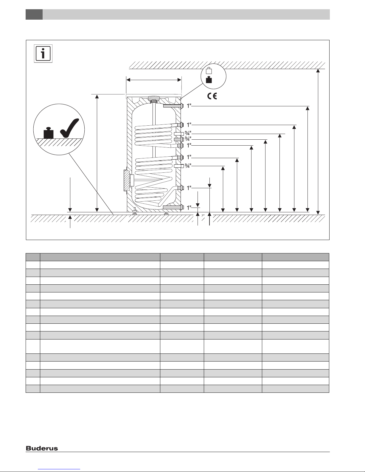
2.7 Physical and connection dimensions
B
B
D
C
Fig. 5 Physical and connection dimensions
A
M1
M2
E
O
P
N
M
L
J
I
K
H
G
F
6 720 800 155-21.2ITL
SM80/5 SM100/5
A Diameter inch (mm) 26-3/8 (670) 26-3/8 (670)
B Minimum floor weight carrying capacity lb (kg) 899 (408) 1135 (515)
C Clearance off floor inch (mm) 3/8 - 3/4 (10 - 20) 3/8 - 3/4 (10 - 20)
D Overall height inch (mm) 58-7/8 (1495) 72-1/4 (1835)
E Height, cold water inlet inch (mm) 3-1/8 (80) 3-1/8 (80)
F Height, solar return inch (mm) 12-1/2 (318) 12-1/2 (318)
G Height, sensor well for temperature sensor (solar) inch (mm) 24-21/64 (618) 31-7/32 (793)
H Height, solar supply inch (mm) 28-1/2 (722) 35-3/8 (898)
i Height, tank return inch (mm) 32 (813) 40-5/8 (1033)
J Height, recirculation connection inch (mm) 35-1/2 (903) 45 (1143)
K Height, sensor well for temperature sensor
(heat source or aquastat)
V Boiler flow connection height inch (mm) 44 (1118) 54-1/2 (1383)
M Height, hot water outlet inch (mm) 53-3/8 (1355) 66-3/4 (1695)
N Minimum room height for anode replacement inch (mm) 72-7/8 (1850) 82-3/4 (2100)
O Empty weight lb (kg) 260 (118) 298 (135)
P Total weight when filled lb (kg) 899 (408) 1135 (515)
Table 6
inch (mm) 39-7/8 (1013) 50-5/16 (1278)
SM80/5, SM100/5 – 6 720 800 156 (2017/07)8
Page 9
Standards, regulations and directives
6 720 647 567-02.1ITL
3
3 Standards, regulations and directives
Observe all local regulations and standards applicable to
installation and operation of the system in your country!
All electrical components must be approved for the USA
and Canada.
4 Moving the tank
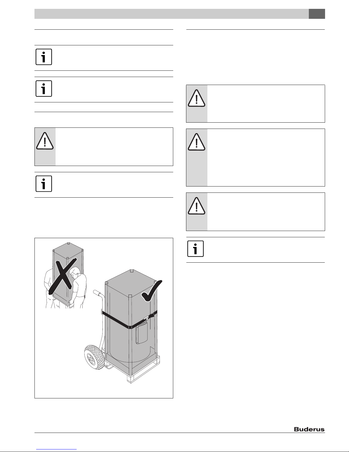
WARNING: Risk of injury from carrying heavy loads and
inadequately securing loads for transport.
▶ Use suitable means of transportation, e.g. a dolly
with strap.
▶ Secure the load against falling.
Where possible, do not remove the DHW tank from its
packaging until it has reached the installation location.
This ensures protection during handling.
▶ Position the dolly at the back of the packed DHW tank.
▶ Secure the DHW tank to the means of transportation with a strap.
▶ Transport the DHW tank to the installation location.
▶ Only remove the DHW tank from the packaging at the installation
location.
5 Installation
The DHW tank is delivered fully assembled.
▶ Check DHW tank for completeness and damage.
5.1 Tank installation
5.1.1 Requirements for installation location
NOTICE: Risk of damage from inadequate load-bearing
capacity of the supporting substructure or unsuitable
floor surface!
▶ Ensure that the installation area is level and offers
sufficient load-bearing capacity.
NOTICE: Risk of damage from stress cracking and
corrosion!
▶ Position the DHW tank in a dry room free from the
risk of freezing.
▶ Install this DHW tank only in closed-loop, unvented
systems.
▶ Open expansion vessels can NOT be used for this
DHW tank.
NOTICE: If l ea ks can re sul t i n pr op er ty d am age or a d rai n
pan is required by law:
▶ Install an adequate drain pan.
▶ Follow the installation instructions of the drain pan
manufacturer.
Follow drain pan manufacturer's instructions.
Fig. 6 Transporting with a dolly
5.1.2 Wall clearances
▶ Place the DHW tank on a plinth if there is a risk that water may collect
at the installation site.
▶ The installation site must be a dry and frost-free room.
▶ Observe minimum room height ( Tab. 6, page 8) and minimum
wall clearance in installation room ( Fig. 7, page 10).
▶ Maintain a distance of 2" (51 mm) from heated pipes and
combustible surfaces.
SM80/5, SM100/5 – 6 720 800 156 (2017/07) 9
Page 10

5
6 720 647 567-05.1ITL
Installation
19-¾ inch
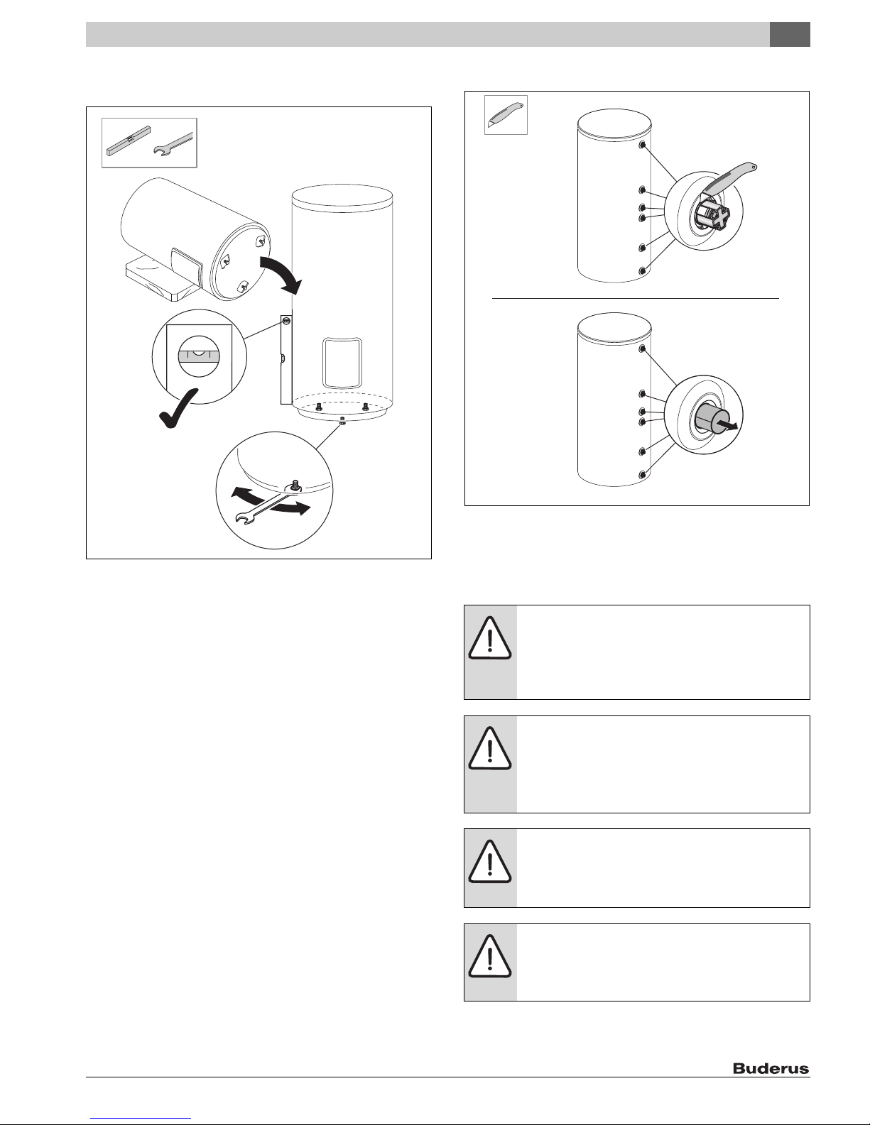
▶ Unscrewing the adjustable foot[3].
(500 mm)
1.
15-¾ inch
(400 mm)
4 inch
(102 mm)
6 720 800 155-10.1ITL
Fig. 7 Recommended minimum wall clearances
5.1.3 Positioning the tank
▶ Unpack the tank by removing the wrap, wooden boards and foam pad
on the top.
▶ Lay the foam pad on the floor to serve as a mat.
2.
3.
6 720 647 567-35.1ITL
Fig. 9 Lay the DHW cylinder on its side and expose the adjustable foot
Fig. 8 Unpacking the DHW tank
▶ Carefully lay the tank on the foam pad [1].
▶ Cut out the protections in the foam bottom [2].
SM80/5, SM100/5 – 6 720 800 156 (2017/07)10
Page 11
Installation
6 720 800 155-22.1ITL
A
B
5
▶ Position the DHW tank on a level floor with adequate load-bearing
capacity.
▶ Remove the caps from the connections.
6 720 647 567-07.1ITL
Fig. 10 Positioning the tank
▶ Maintain minimum wall clearances.
▶ Using the adjustable foot, align the DHW cylinder vertically.
Fig. 11 Remove caps
▶ Use Teflon tape or Teflon cord to seal the connections. Do not use
hemp to seal the connections.
5.2 Water connections
WARNING: Risk of fire from soldering and brazing!
▶ Take appropriate protective measures when
soldering and welding as the insulation is flammable,
for example, cover the insulation.
▶ Check tank jacket for damage after completing work.
DANGER: Risk of injury from contaminated water!
Work carried out without due care for cleanliness
contaminates the drinking water.
▶ Install in accordance with national standards and
guidelines.
NOTICE: Water damage
▶ Connect the drain to the bottom tank connection
prior to filling the tank.
▶ Seal off all unused tank connections.
SM80/5, SM100/5 – 6 720 800 156 (2017/07) 11
NOTICE: Risk of corrosion from damage to the enamel
coating!
▶ Attach connections to the DHW tank only "hand-
tight".
Page 12
5
6 720 800 155-11.1ITL
1
1
6 720 800 155-05.1ITL
Installation
5.2.1 Connecting the tank on the water side
Example of system with all recommended valves ( Fig. 12, page 12).
▶ When selecting the expansion vessel for the hot water side, take the
content of the heat exchanger and DHW tank into consideration.
▶ Route the connection cables for the tank temperature sensors at the
back of the tank through the insulation to the heating appliance or
controller.
▶ Install piping runs so that natural circulation is prevented. If
necessary, install check valves.
▶ Install connection cables free of stress.
▶ Attach piping to the tank connections on-site.
▶ Check all connections for leaks.
5.2.2 Installing a T&P safety valve (on-site)
▶ Install a listed T&P safety valve that is approved for drinking water
( ¾ ")in the DHW outlet.
▶ This DHW tank must be installed with a new T&P safety valve.
▶ The T&P valve must be sized no smaller than the rated tank capacity.
▶ Observe the safety valve installation instructions.
▶ T&P discharge pipe:
– T he bl ow-o ff l ine m ust be at lea st equal to the outlet cross-section
of the safety valve.
– Route the blow-off line from the T&P valve directly to an adequate
drain (maximum length 6 ft (2 m) with no more than two 90°elbows).
– The discharge line must terminate at an adequate drain in order to
prevent property damage from spillage.
– Check that the T&P safety valve operates properly at least once
annually.
▶ Never plug the blow-off line. During heating, water may be
discharged for operational reasons at any time.
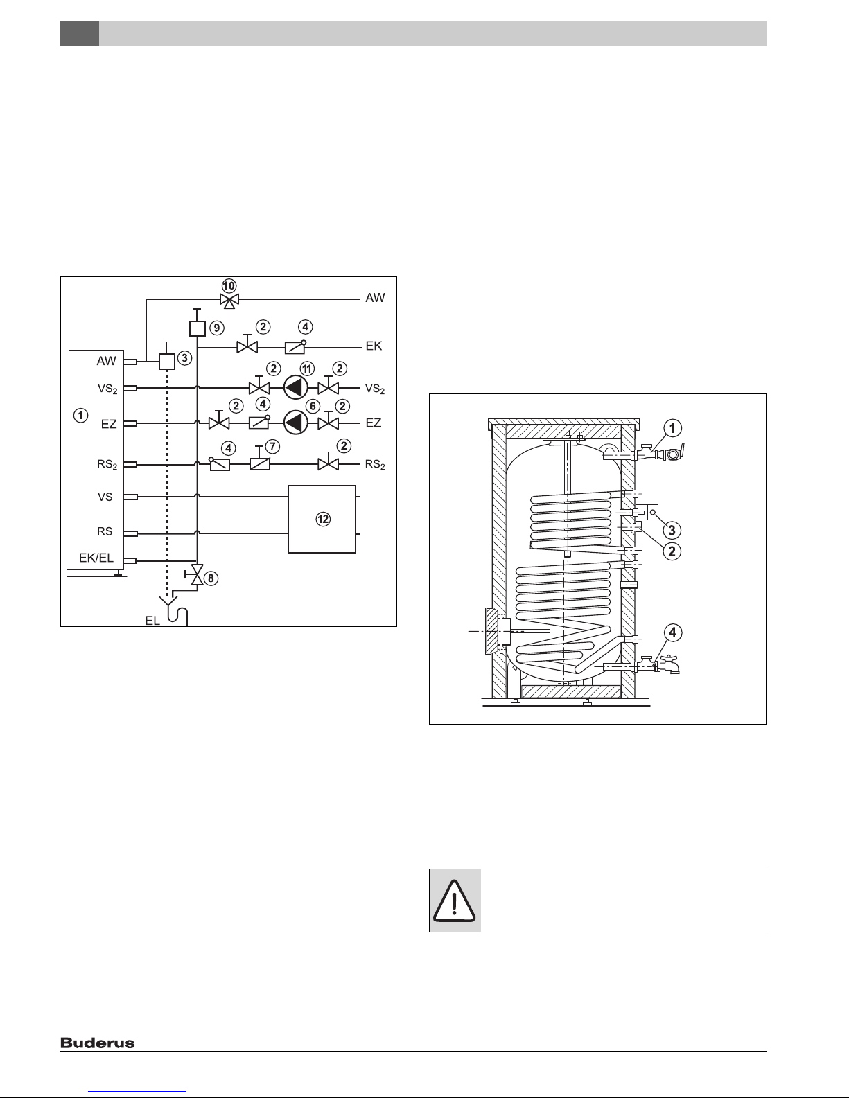
Fitting the B-kit
Fig. 12 Installation (illustrative)
[1] Storage tank
[2] Shutoff valve
[3] P&T safety valve (combined with hot water outlet)
[4] Check valve
[5] Tank primary pump
[6] Recirculation pump (optional)
[7] Air eliminator (in main supply)
[8] Drain valve
[9] Expansion vessel
[10] Thermostatic DHW mixing valve
[11] Tank primary pump
[12] Solar pump station
[AW] DHW outlet
[EZ] Recirculation inlet
[VS1] Tank supply (solar)
[RS1] Tank return (solar)
[VS2] Tank supply (boiler)
[RS2] Tank return (boiler)
[EK] Cold water inlet
[EL] Tank drain
Fig. 13 Connecting the DHW tank components
[1] Tee 1" x 1" x 3/4" (2x) with T&P safety valve
[2] 3/4" cap for recirculation connection
[3] Bracket with Aquastat
[4] Tee with fill and drain valve
5.3 Installing the DHW water temperature sensor
(accessory) or Aquastat (accessory)
DANGER: Risk of fatal injury from electric shock.
▶ Isolate the system electrically prior to commencing
work on the system.
SM80/5, SM100/5 – 6 720 800 156 (2017/07)12
Page 13
Installation
6 720 800 155-03.1ITL
5
Connect the electrical power and set the temperature on
the DHW temperature sensor or the aquastat as shown in
the respective aquastat or control manufacturer's
instructions.
Install a tank temperature sensor or an aquastat on the DHW tank to
measure and monitor the hot water temperature.
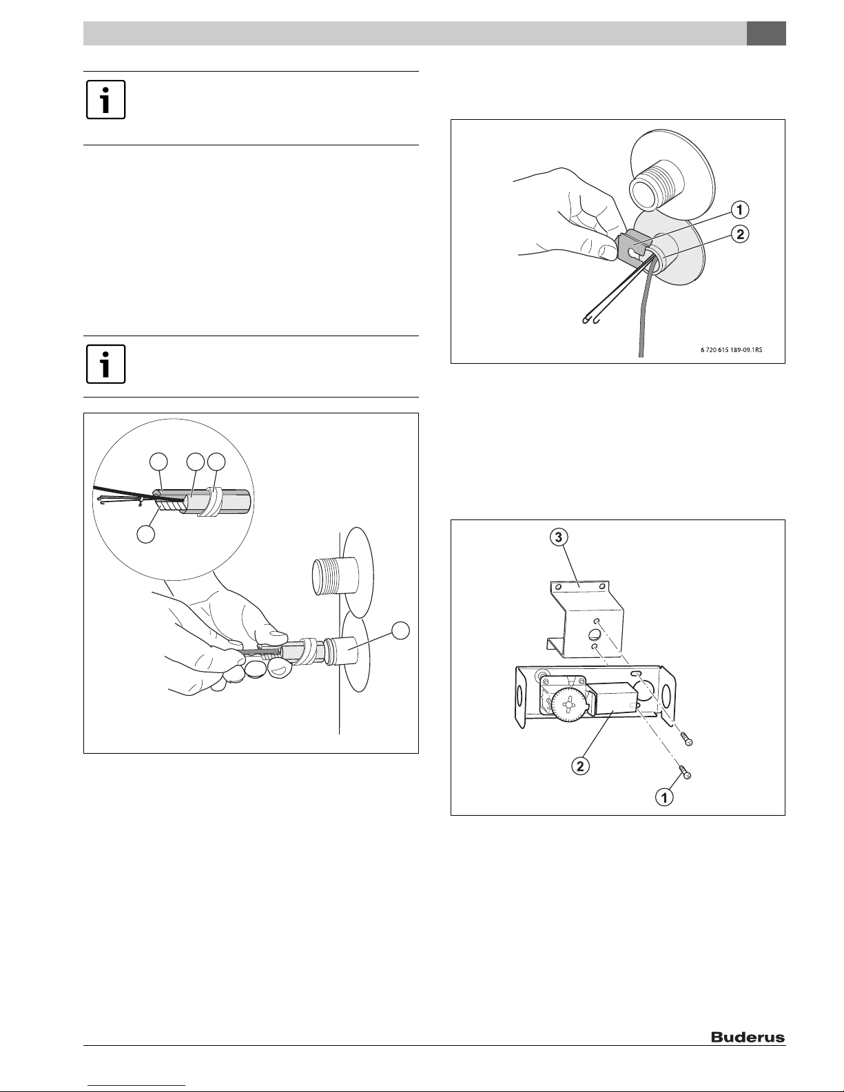
Installing the DHW temperature sensor
▶ Take the tank temperature sensor from the scope of delivery of the
control panel (accessories).
▶ Insert the sensor set until it bottoms out inside the sensor well [5].
This automatically pushes back the plastic spiral [3] that holds the
sensor set together.
The compensating spring [4] ensures contact between the sensor well
and sensor surfaces, and a reliable temperature reading.
Always ensure that the full length of the sensor surface is
in contact with the sensor well.
123
▶ In the case a sensor is being used without a compensating spring, the
empty space in the sensor well must be filled with a sufficient amount
of heat-conducting paste.
Fig. 15 Installing the sensor retainer
[1] Sensor retainer
[2] Sensor Well
Installing the aquastat
▶ Remove cover from the aquastat. To do so, undo the screw on the
top.
▶ If necessary, remove any unnecessary attachments. Attach bracket
[3] to aquastat [2] by means of two self-tapping screws [1].
4
5
6 720 800 155-17.1ITL
Fig. 14 Installing the DHW temperature sensor
[1] Quarter-circle spacer
[2] Temperature sensor
[3] Plastic spiral
[4] Compensating spring
[5] Sensor Well
▶ Push sensor retaining clip [1] from the side onto sensor well [2].
▶ Route the sensor lead to the boiler or control panel and ensure the
cable is not strained. This piping must not be in contact with any hot
boiler parts.
Fig. 16 Screw the bracket onto the aquastat
[1] Self-tapping screws
[2] Aquastat
[3] Holder
SM80/5, SM100/5 – 6 720 800 156 (2017/07) 13
Page 14
5
6 720 800 155-04.1ITL
5
4
3
2 1
6
Installation
▶ Feed the temperature sensor [4] with the compensating spring [3]
into the sensor well [5].
▶ Attach bracket [6] to DHW cylinder by means of 4 self-tapping sheet
metal screws [1].
▶ Replace the cover of the aquastat [2].
Fig. 17 Installing the aquastat
[1] Self-tapping screws
[2] Aquastat
[3] Compensating spring
[4] Temperature sensor
[5] Sensor Well
[6] Holder
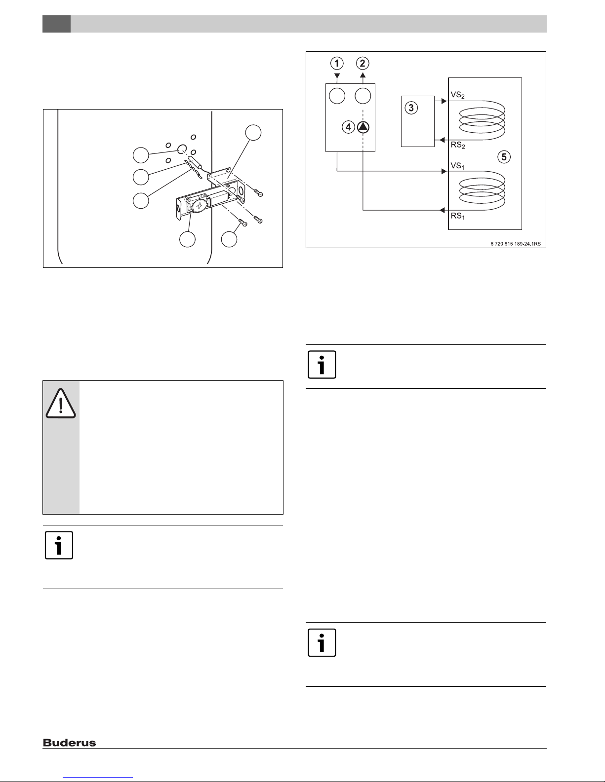
5.4 Connecting the KS solar pump station
Fig. 18 Connecting the KS solar pump station (schematic illustration)
[1] Collector supply connection
[2] Collector return connection
[3] Oil-/gas-fired boiler
[4] Solar pump station
[5] DHW tanks
Grounding the piping
Allow only an authorized contractor to make all the
piping connections.
WARNING: Risk of equipment damage from very high
operating temperatures and pressures!
▶ Use pressure- and temperature-resistant piping
materials.
▶ Do not use any galvanized piping, pipe connections
or graphite seals.
▶ Do not use any plastic piping or connections of any
kind.
▶ When using soldered connections in the entire solar
circuit, use high-temperature solder (melting point
455 °F (235 °C)).
To ensure proper operation of the solar thermal system,
air must be bled adequately from the entire system.
For information on bleeding the solar thermal system,
refer to the installation instructions for the KS solar
pump station.
▶ Attach the KS solar pump station [4] to the lower heat exchanger in
the DHW tank at the VS1 (solar supply) and RS1 (solar return)
connections.
▶ Attach the reheating device to the upper heat exchanger in the DHW
tank at the VS2 (storage tank supply) and RS2 (storage tank return)
connections.
▶ Use piping and pipe connections made of copper, brass and non-
galvanized steel for the connection between the KS solar pump
station [4] and DHW tank [5].
▶ Attach one grounding clamp each to the supply and return pipes (at
any position).
▶ Connect the grounding clamps to the building's grounding rod by
means of standard bonding cables AWG9.
Laying pipes with an automatic air vent valve on the roof (available
as accessory)
▶ Pipes to the air vent valve should follow a rising gradient. For every
downwards change of direction, an additional air separator with air
vent valve is required (heat-resistant to 302 °F (150 °C)).
5.5 Connection as high-performance DHW tank
The DHW tank can also be used as a high-performance DHW tank.
In this case, 2 connection configurations are possible.
5.5.1 Series connection of the lower and upper heat exchanger
▶ Attach the upper connection on the lower heat exchanger to the
lower connection on the upper heat exchanger in the DHW tank.
▶ Attach the tank charging pump to the upper connection on the upper
heat exchanger.
When the heat exchangers are connected in series, the
pressure loss across the two coils is cumulative.
Pressure drop of connecting pipe must be added. Ensure
that the pump used can handle the resulting pressure
drop.
▶ Attach the lower connection on the lower heat exchanger to the
return piping on the boiler.
SM80/5, SM100/5 – 6 720 800 156 (2017/07)14
Page 15
Start-up procedure
6
▶ Install the Aquastat or DHW temperature sensor in the sensor well
provided for this purpose ( Fig. 2, page 5, [3]).
5.5.2 Parallel connection of the lower and upper heat exchanger
We recommend that the two heat exchangers in the tank each be
connected to its own primary pump.
6 Start-up procedure
NOTICE: Risk of equipment damage from excess
pressure! Excess pressure can cause stress cracking in
the enamel.
▶ Never close the temperature and pressure safety
valve blow-off line.
6.1 Commissioning the DHW tank
Have the installer of the heating system or a qualified contractor
commission the equipment.
▶ Commission the boiler and other accessories in accordance with the
manufacturer's instructions in the corresponding installation and
operating manuals.
Use only drinking water to check the DHW tank for leaks.
On the DHW side, the test pressure must not exceed
150 psi (10.3 bar) gauge pressure.
▶ To bleed air from the DHW tank, open the highest tap/valve.
▶ To fill the DHW tank, open the shut-off valve for the cold water inlet.
▶ Flush the tank and piping thoroughly prior to commissioning.
▶ Before heating up, verify that the boiler, tank and pipework are filled
with water. Open the air bleeder valve for this purpose.
▶ Check all connections, piping and the inspection port for leaks.
▶ To prevent corrosion, dry out the inner space and keep the
inspection port covers open.
7.2 Shutting down the heating system when there is a
risk of frost
▶ Shut down the heating system and the DHW tank as shown in
Chapter 7.1.
Drain the DHW tank completely, even the lower chamber
of the tank and the heat exchanger.
8 Environmental protection/disposal
Environmental protection is one of the fundamental company policies of
the Bosch Group. We regard quality of performance, economy and
environmental protection as equal objectives.
Environmental protection laws and regulations are strictly adhered to.
To protect the environment, we use the best possible technology and
materials taking into account economic points of view.
Packaging
For the packaging, we participate in the country-specific recycling
systems, which guarantee optimal recycling. All packaging materials
used are environmentally-friendly and recyclable.
Old electrical and electronic appliances
Electrical or electronic devices that are no longer
serviceable must be collected separately and sent for
environmentally compatible recycling (in accordance
with the European Waste Electrical and Electronic
Equipment Directive).
To dispose of old electrical or electronic devices, you
should use the return and collection systems put in place
in the country concerned.
7 Shutdown
NOTICE: Risk of tank damage!
Residual moisture can result in corrosion.
▶ Thoroughly dry out the inside (e. g. by means of hot
air) and leave the cleanout cover open.
7.1 Shutting down the tank
WARNING: Risk of scalding from hot water!
▶ Let the tank cool down sufficiently.
▶ Switch off the temperature controller at the control panel, shut of the
heating system emergency shutoff switch, or disengage the heating
system circuit breaker.
▶ Close the cold water inlet shutoff valve.
▶ Drain the DHW tank via the drain valve by opening the highest faucet.
▶ Close the shut-off valves to and from the boiler.
▶ Depressurize the heat exchanger.
▶ Drain and blow out the heat exchanger.
9 Maintenance
▶ Allow the DHW tank to cool down sufficiently before performing any
maintenance.
▶ Remedy all faults immediately.
▶ Use original spare parts only!
▶ The tank must be inspected annually and maintained as required.
▶ Check the T&P safety valve annually.
9.1 Preparing the DHW tank for cleaning
WARNING: Risk of scalding!
Hot water can cause scalding.
▶ Prior to cleaning, allow the DHW tank to cool down
sufficiently.
▶ Disconnect electrical power from the heating system.
▶ Drain the DHW tank. To do so, close the shut-off valve for cold water
inlet and the open drain valve. To vent the system, open the air vent
valve or the highest faucet.
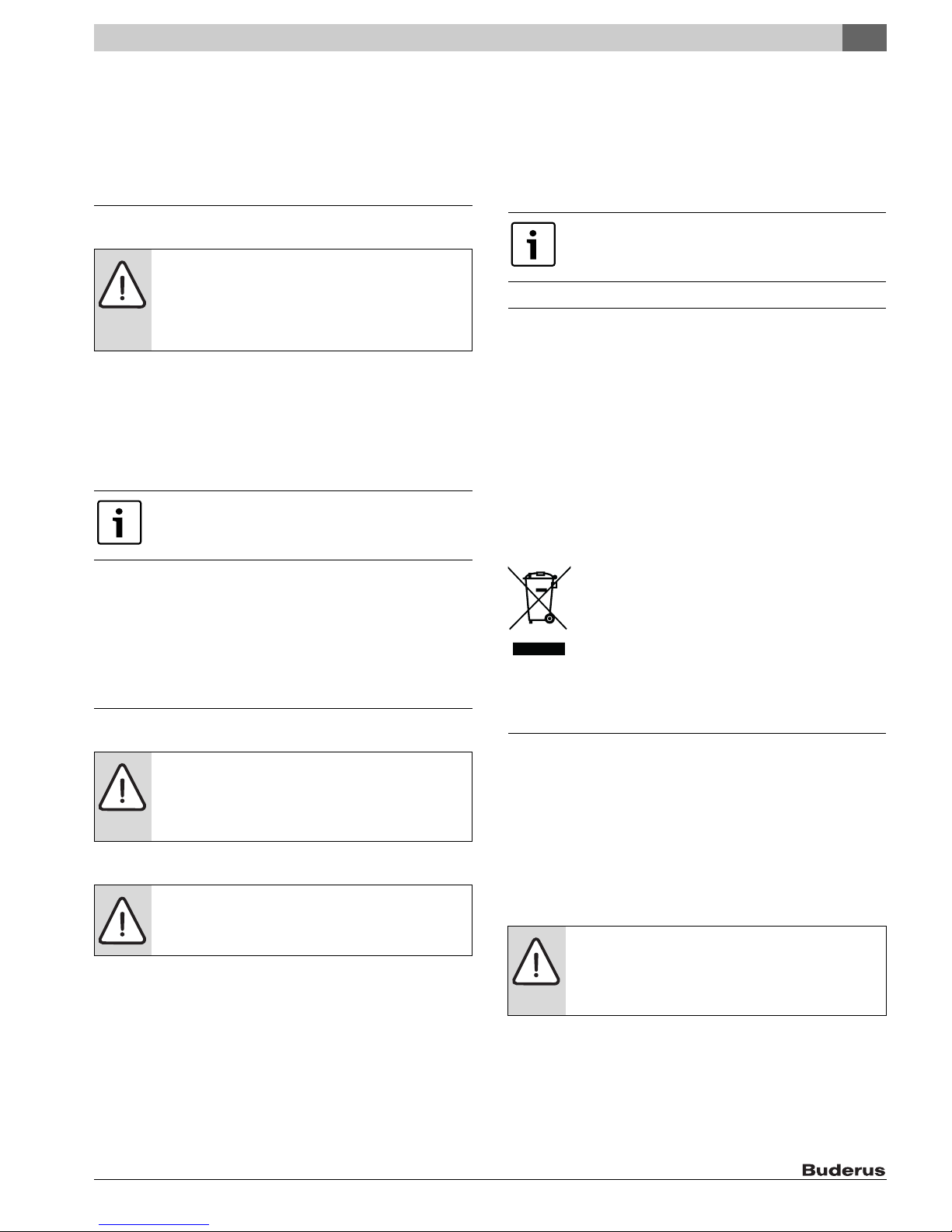
▶ Remove the cleanout cover [6] shroud over the inspection port [1] in
the DHW tank.
SM80/5, SM100/5 – 6 720 800 156 (2017/07) 15
Page 16
9
6720 800 155-02.1ITL
Maintenance
▶ Loosen the hex bolts [5] in the cleanout cover [4].
▶ Remove the cleanout cover [4], magnesium anode [3] and cleanout
cover gasket [2].
Fig. 20 Hosing down the interior of the DHW tank
Fig. 19 Removing the cleanout cover
[1] Inspection port
[2] Handhole cover gasket
[3] Magnesium anode
[4] Handhole cover
[5] Hex bolts
[6] Cleanout cover shroud
9.2 Descaling/cleaning the tank
▶ Check the DHW tank interior for scale deposits (calcium).
NOTICE: Risk of tank damage due to damaged enamel.
▶ Never use hard objects or tools with sharp edges to
clean the interior of the tank.
Should limescale be discovered inside the DHW tank, proceed as
follows:
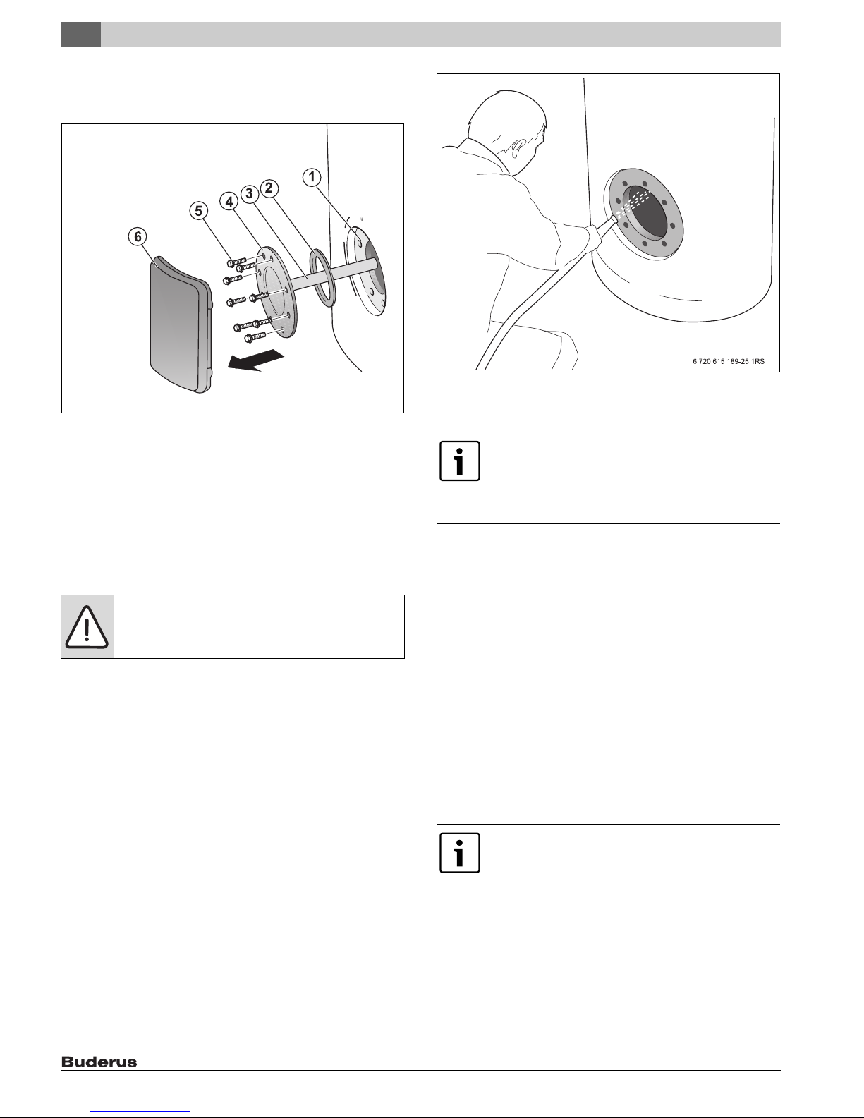
▶ Hose down the inside of the DHW tank with a "high pressure"
(approx. 58 – 72.5 psi (4 – 5 bar) gauge pressure) stream of cold
water ( Fig. 20, page 16).
You can increase the cleaning effect by heating up the heat exchangers
in the drained DHW tank before cleaning. The thermal shock effect
releases scale deposits more easily from the coil-type heat exchanger.
▶ Use a wet & dry vacuum cleaner with plastic suction hose to remove
the residues.
Extremely tough limescale inside the DHW tank can be removed by
chemical means. We recommend that you have a qualified contractor
carry out the chemical cleaning operation.
9.3 Check the magnesium anodes
The warranty is void if the magnesium anode is not
correctly maintained. Annual service records must be
kept in a safe location and submitted together with the
original purchase receipt in the event of a warranty
claim.
The purpose of the magnesium anode is to protect the storage tank
against corrosion.
Every year, check whether the magnesium anode must be replaced. The
surface of the magnesium anode must be free of deposits.
If the rod surface appears pitted, bumpy, rusty, deposits have built up on
the surface, or if the rod is less than 5/8" (15 mm) in diameter, then it
must be replaced.
Certain installations may require more frequent replacement of the
magnesium anode rod:
• Recirculation connection
• Poor water quality
• Galvanic/electrolytic corrosion
• High flow rate
In the event of poor water quality it is recommended that a water
treatment professional be consulted for water treatment options. The
DHW cylinder warranty is void if the magnesium anode is not correctly
maintained.
Never bring the magnesium anode surface into contact
with oil or grease.
▶ Keep everything clean.
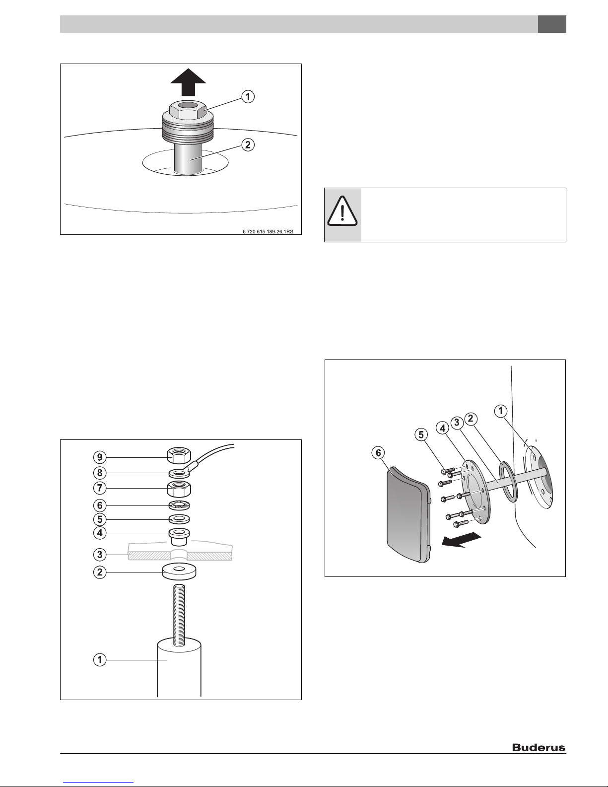
Checking the top magnesium anode
▶ Remove PS top cover if not already removed.
▶ Unscrew the magnesium anodes.
▶ Check the magnesium anodes for degradation.
▶ Replace the magnesium anode if the diameter has decreased to
approx. 5/8" (15 mm).
SM80/5, SM100/5 – 6 720 800 156 (2017/07)16
Page 17
Maintenance
6 720 800 155-23.1ITL
6720 800 155-02.1ITL
9
▶ Insert the magnesium anodes into the sleeve again.
Fig. 21 Checking the top magnesium anode
[1] Hex bolt
[2] Magnesium anode
Checking the side magnesium anode
▶ Empty the DHW cylinder as described in Chapter 9.1.
▶ Remove cleanout cover ( Fig. 19, page 16), if it is not already
removed.
▶ Check the magnesium anodes.
▶ Replace the magnesium anode if the diameter has decreased to
approx. 5/8" (15 mm).
▶ Unscrew the nut M8 [9] to release the eyelet of the grounding cable
connecting lead[8].
▶ Unscrew the M8 nut [7].
▶ Remove the handhole cover [1] from the magnesium anode [3].
▶ Fit the new magnesium anode together with all small parts supplied
with it.
Key to Fig. 22:
[1] Magnesium anode
[2] Gasket
[3] Handhole cover
[4] Insulating sleeve
[5] Dished washer
[6] Serrated washer
[7] M8 Nut
[8] Eyelet of the grounding cable connecting lead
[9] M8 Nut
9.4 Startup after maintenance
NOTICE: Risk of tank damage from a faulty gasket!
▶ To prevent the DHW tank from leaking, install a new
cleanout cover gasket upon completion of cleaning
and maintenance.
▶ Put the cleanout cover [4] back in place together with the new gasket
[2].
▶ Thread hex bolts [5] into cleanout cover [4] "hand-tight".
▶ Then use a torque wrench to tighten the hex bolts to 18-22 lbf-ft
(25 – 30 Nm).
▶ Fill the DHW tank and restart the heating system.
▶ Check all connections and the inspection port for leaks.
▶ Replace the cleanout cover shroud.
▶ Reinstall the PS jacket cover ( Fig. 2, page 5) on the DHW tank.
Fig. 22 Replacing the magnesium anode
SM80/5, SM100/5 – 6 720 800 156 (2017/07) 17
Fig. 23 Reinstall handhole cover
[1] Inspection port
[2] Handhole cover gasket
[3] Magnesium anode
[4] Handhole cover
[5] Hex bolts
[6] Cleanout cover shroud
Page 18

10
Spare Parts
10 Spare Parts
10.1 Spare parts for SM80/5, SM100/5
1
2
10
9
8
9
11
5
3
Fig. 24 DHW tank SM80/5, SM100/5
13
14
7
9
6
5
5
5
6 720 800 155-20.1ITL
Item Description Part number
1 Cover D670 lid, black 8 718 541 369 0
2 Plug, EPS upper part D672.5 8 718 541 767 0
3 Cleanout gasket D670, black 8 718 542 063 0
5 Self-tapping hex screw M10x25 (8x) 7 747 005 744
6 Cleanout cover DN120 for anode 7 747 004 739
7 O-ring 120.02x6.99-N 8 718 572 538 0
8 Anode D33x400 mm 8 718 571 568 0
9 Anode mounting kit (10x) screw-in 5264278
Table 7 Spare parts for SM80/5, SM100/5
Item Description Part number
10 Anode G1 1/2 x 750,
without electrical insulation D=33
10 Anode G1 1/2 x 600,
without electrical insulation D=40
11 Anode grounding cable (insulated) 63037168
13 Self-tapping screw St 4.2x13 (10x) 7 747 027 696
14 Retaining plate for the aquastat 7 747 028 761 0
Logo Buderus 8 718 541 573
8 718 542 778 0
8 718 542 704 0
Table 7 Spare parts for SM80/5, SM100/5
SM80/5, SM100/5 – 6 720 800 156 (2017/07)18
Page 19

Table des matières
Table des matières
1 Explication des symboles et mesures de sécurité . . . . . . . . . 20
1.1 Explication des symboles . . . . . . . . . . . . . . . . . . . . . . . 20
1.2 Consignes de sécurité . . . . . . . . . . . . . . . . . . . . . . . . . . 20
1.3 Initiation de l’utilisateur . . . . . . . . . . . . . . . . . . . . . . . . . 21
2 Description du produit . . . . . . . . . . . . . . . . . . . . . . . . . . . . . . . 21
2.1 Fourniture . . . . . . . . . . . . . . . . . . . . . . . . . . . . . . . . . . . . 21
2.2 Utilisation conforme à l’usage prévu . . . . . . . . . . . . . . . 22
2.3 Description du produit . . . . . . . . . . . . . . . . . . . . . . . . . . 22
2.4 Plaque signalétique . . . . . . . . . . . . . . . . . . . . . . . . . . . . 22
2.5 Courbe des pertes de pression échangeur thermique . 23
2.6 Données techniques . . . . . . . . . . . . . . . . . . . . . . . . . . . 24
2.7 Cotes de construction et de raccordement . . . . . . . . . 25
3 Normes, prescriptions et directives . . . . . . . . . . . . . . . . . . . . 26
4 Transport . . . . . . . . . . . . . . . . . . . . . . . . . . . . . . . . . . . . . . . . . . . 26
5 Montage . . . . . . . . . . . . . . . . . . . . . . . . . . . . . . . . . . . . . . . . . . . . 26
5.1 Mise en place . . . . . . . . . . . . . . . . . . . . . . . . . . . . . . . . . 26
5.1.1 Exigences requises pour le lieu d’installation . . . . . . . . 26
5.1.2 Distances par rapport aux murs . . . . . . . . . . . . . . . . . . 27
5.1.3 Mise en place du ballon d’eau chaude sanitaire . . . . . . 27
5.2 Raccordements hydrauliques . . . . . . . . . . . . . . . . . . . . 28
5.2.1 Effectuer le raccordement hydraulique du ballon d’eau
chaude sanitaire . . . . . . . . . . . . . . . . . . . . . . . . . . . . . . 29
5.2.2 Installer la soupape de sécurité pour la température
et la pression (sur site) . . . . . . . . . . . . . . . . . . . . . . . . . 29
5.3 Installation de la sonde de température ECS
(accessoire) ou de l’Aquastat (accessoire) . . . . . . . . . 30
5.4 Raccordement de la station de pompe solaire KS . . . . 31
5.5 Raccordement en tant que ballon ECS grande
puissance . . . . . . . . . . . . . . . . . . . . . . . . . . . . . . . . . . . . 31
5.5.1 Raccordement en série des échangeurs thermiques
inférieur et supérieur . . . . . . . . . . . . . . . . . . . . . . . . . . 31
5.5.2 Raccordement en parallèle des échangeurs thermiques
inférieur et supérieur . . . . . . . . . . . . . . . . . . . . . . . . . . 32
9 Entretien . . . . . . . . . . . . . . . . . . . . . . . . . . . . . . . . . . . . . . . . . . 33
9.1 Préparer le ballon d’eau chaude sanitaire pour le
nettoyage . . . . . . . . . . . . . . . . . . . . . . . . . . . . . . . . . . . . . 33
9.2 Détartrer/nettoyer le ballon d'eau chaude sanitaire . . 33
9.3 Vérifier les anodes en magnésium . . . . . . . . . . . . . . . . 33
9.4 Mise en service après maintenance . . . . . . . . . . . . . . . 34
10 Pièces de rechange . . . . . . . . . . . . . . . . . . . . . . . . . . . . . . . . . . 36
10.1 Pièces de rechange pour SM80/5, SM100/5 . . . . . . . 36
6 Mise en service . . . . . . . . . . . . . . . . . . . . . . . . . . . . . . . . . . . . . . 32
6.1 Mise en service du ballon d’eau chaude sanitaire . . . . 32
7 Mise hors service . . . . . . . . . . . . . . . . . . . . . . . . . . . . . . . . . . . . 32
7.1 Mise hors service du ballon d’eau chaude sanitaire . . . 32
7.2 Mise hors service de l’installation de chauffage
en cas de risques de gel . . . . . . . . . . . . . . . . . . . . . . . . 32
8 Protection de l’environnement/
Recyclage . . . . . . . . . . . . . . . . . . . . . . . . . . . . . . . . . . . . . . . . . . 32
SM80/5, SM100/5 – 6 720 800 156 (2017/07) 19
Page 20

1
Explication des symboles et mesures de sécurité
1 Explication des symboles et mesures de
sécurité
1.1 Explication des symboles
Avertissements
Les avertissements sont indiqués dans le texte par un
triangle de signalisation.
En outre, les mots de signalement caractérisent le type
et l’importance des conséquences éventuelles si les mesures nécessaires pour éviter le danger ne sont pas respectées.
Les mots de signalement suivants sont définis et peuvent être utilisés
dans le présent document :
• AVIS signale le risque de dégâts matériels.
• PRUDENCE signale le risque d’accidents corporels légers à moyens.
• AVERTISSEMENT signale le risque d’accidents corporels graves à
mortels.
• DANGER signale la survenue d’accidents mortels en cas de non res-
pect.
Informations importantes
Interdiction :
Il est formellement interdit de raccorder le potentiostat d'une anode
externe à l'anode au magnésium montée dans un ballon ! Le ballon serait
endommagé ! Le droit de garantie serait perdu.
Installation et mise en service
▶ Le raccordement électrique doit être réalisé exclusivement par un
électricien. Respecter le schéma de connexion !
▶ Ne pas monter cet appareil dans des pièces humides (par ex. salle de
bain, sauna).
Fonction
▶ Respecter cette notice d’installation et d’entretien afin de garantir un
fonctionnement parfait.
▶ Ne pas obturer la conduite de purge de la soupape de sécurité T&D.
Pendant le chauffage, de l’eau risque de s’écouler pour des raisons
de sécurité.
Risques d’électrocution
▶ S’assurer que seuls des électriciens autorisés réalisent ces travaux
électriques.
▶ Avant de commencer les travaux d’électricité, couper le courant du
câble d’alimentation sur tous les pôles et protéger l’installation
contre tout réenclenchement involontaire.
▶ Vérifier que l’installation est hors tension.
Les informations importantes ne concernant pas de situations à risques pour l'homme ou le matériel sont signalées par le symbole ci-contre. Elles sont limitées par
des lignes dans la partie inférieure et supérieure du
texte.
Autres symboles
Symbole Fonction
▶Etape à suivre
Renvois à un autre passage dans le document
• Enumération/Enregistrement dans la liste
– Enumération / Entrée de la liste (2e niveau)
Tab. 1
1.2 Consignes de sécurité
Lisez attentivement toutes les consignes avant l’installation. Exécuter
les étapes dans l’ordre indiqué. Faire contrôler le ballon d’eau chaude
sanitaire par un technicien qualifié au moins une fois par an. Le non-respect de ces consignes peut entraîner des accidents graves voire mortels
et/ou des dégâts matériels.
Montage et entretien
▶ Risque d’incendie en raison des travaux de soudure !
L’isolation thermique étant inflammable, prendre des mesures de
sécurité appropriées pour effectuer tous les travaux de soudage, en
recouvrant l’isolation thermique par ex.
▶ S’assurer que les travaux d’installation et de maintenance sont exclu-
sivement réalisés par un professionnel agréé.
▶ Utiliser des matériaux suffisamment résistants aux températures éle-
vées.
Risques de brûlure aux points de puisage de l’eau chaude sanitaire
▶ Les températures du ballon d’eau chaude sanitaire pendant son fonc -
tionnement peuvent dépasser 122 °F (50 °C). Pour limiter la température de puisage, installer un mélangeur thermostatique.
▶ L’eau chauffée utilisée pour la lessive, la vaisselle et d’autres tâches
de nettoyage peut provoquer des brûlures et des blessures permanentes.
▶ Chez les enfants, les personnes âgées et sénile ou mentalement han-
dicapée, il existe un risque accru de blessure permanente à l’eau
chaude. Ne jamais laisser ces personnes sans surveillance dans la
baignoire ou sous la douche. Ne pas autoriser les jeunes enfants à
actionner eux-mêmes les robinets d’eau chaude ou de remplir une
baignoire.
▶ Si dans un bâtiment les personnes comprises dans les catégories
précédemment citées actionnent des robinets d’eau chaude ou si les
directives locales imposent des températures précises pour les robinets d’eau chaude, prendre les mesures spécifiques suivantes :
– Utiliser le réglage de température le plus bas possible.
– Installer une sécurité anti-brûlure, par ex. une vanne mélangeur
automatique, sur le robinet d’eau chaude ou le chauffe-eau. Choisir et installer la vanne mélangeur automatique en fonction des
recommandations et consignes du fabricant de la vanne.
▶ L’eau s’échappant des vannes de vidange peut être extrêmement
chaude. Pour éviter les blessures :
– Assurer l’étanchéité des raccordements.
– Eloigner les écoulements d’eau de toute personne.
▶ Prendre des mesures de protection contre les températures et pres-
sions trop élevées ! Installer impérativement une soupape de sécurité pour la température et la pression.
Le tableau suivant présente le rapport entre la température de l’eau et le
temps nécessaire à l’apparition de brûlures. Vous pouvez ainsi déterminer les températures d’eau les plus sûres pour votre application.
SM80/5, SM100/5 – 6 720 800 156 (2017/07)20
Page 21

Description du produit
6 720 805 397-01.1ITL
1
2
4
3
5
7
6
2
Température Temps jusqu’à brûlure importante
120 °F (48 °C) plus de 5 minutes
125 °F (51 °C) 1,5 à 2 minutes
130 °F (54 °C) env. 30 secondes
135 °F (57 °C) env. 10 secondes
140 °F (60 °C) moins de 5 secondes
145 °F (62 °C) moins de 3 secondes
150 °F (65 °C) env. 1,5 secondes
155 °F (68 °C) env. 1 seconde
Tab. 2 Rapport approximatif temps-température lors de l’apparition
de brûlures
1. Source : Moritz, A.R. et Henriques, F.C., Jr. (1947). Etudes sur les blessures
thermiques. II. L’importance relative du temps et de la température de surface à
l’origine des brûlures de la peau, American Journal of Pathologie, 23, 695-720.
Pour maintenir la protection anti-corrosion et respecter les règles de
sécurité électrique, veuillez tenir compte des points suivants :
▶ Sur les installations de réchauffage d’eau potable équipées de
conduites en plastique, utiliser des raccords métalliques.
▶ Utiliser des accessoires d’origine.
▶ Après avoir terminé l’installation complète du ballon, effectuer un
contrôler des courants de fuite (inclure également les raccordsunions métalliques de raccordement).
Entretien
Recommandation pour le client :
▶ Conclure un contrat d’entretien et d’inspection avec un chauffagiste
professionnel ou avec le service après-vente My Service. Inspecter le
ballon une fois par an et faire les travaux de maintenance si nécessaire. Travaux de service en fonction des besoins.
▶ Utiliser uniquement des pièces de rechange d’origine.
1
▶ Expliquer comment utiliser et manipuler l'installation de chauffage et
le ballon d'eau chaude sanitaire et attirer l’attention sur les problèmes de sécurité technique.
▶ Expliquer le fonctionnement et le contrôle de la soupape de sécurité
T&D.
▶ Remettre à l’utilisateur tous les documents ci-joints.
▶ Recommandation destinée à l’exploitant : conclure un contrat
d’entretien et d’inspection avec un professionnel agréé.
▶ Attirer l’attention de l’utilisateur sur les points suivants :
– Pendant la mise en température, de l’eau peut s’écouler par la
soupape de sécurité T&D.
– La conduite de purge de la soupape de sécurité T&D doit toujours
rester ouverte.
– Vérifier le bon fonctionnement de la soupape de T&D au moins
une fois par an.
– Inspecter le ballon une fois par an et faire la maintenance si néces-
saire.
2 Description du produit
2.1 Fourniture
• Ballon d’eau chaude sanitaire
• Composants du kit du ballon
• Notice d’installation et d’entretien
Inondation
▶ Ne pas utiliser l’appareil après l’inondation si l’une des pièces était
sous eau. Les éventuels dommages subis par les appareils submergés peuvent être très importants et cacher de nombreux risques pour
la sécurité.
▶ Chaque appareil submergé doit être remplacé.
1.3 Initiation de l’utilisateur
AVERTISSEMENT : Risques de brûlure aux points de
puisage de l’eau chaude sanitaire !
Si la température d’eau chaude sanitaire est réglée à
plus de 122 °F (50 °C) et pendant la désinfection ther-
mique, il y a risque de brûlures aux points de puisage de
l’eau chaude sanitaire.
▶ Rendre le client attentif au fait que l’eau chaude ne
peut pas être ouverte sans la mélanger avec de l’eau
froide. Dans le cas contraire, installer un mélangeur
thermostatique.
AVIS : Dégâts sur le ballon dus à une pression élevée non
autorisée.
▶ Ne jamais obturer la conduite d’écoulement de la
soupape de sécurité pour la température et la pression.
Fig. 1 Composants du kit du ballon
[1] Raccord en T 1" x 1" x 3/4" (2x)
[2] Soupape de sécurité température et pression
[3] Capuchon du raccord bouclage 3/4"
[4] Robinet de vidange
[5] Support pour Aquastat, vis pour support de l’Aquastat (4x)
[6] Ressort compensateur pour sonde de température de l’Aquastat
ou du ballon
[7] Pièces borgnes quart de rond pour la sonde de température de
l’Aquastat ou du ballon (2x)
SM80/5, SM100/5 – 6 720 800 156 (2017/07) 21
Page 22

2
Description du produit
2.2 Utilisation conforme à l’usage prévu
Le ballon ECS peut être réchauffé via un système de chauffage solaire
avec une chaudière en tant que système back-up ou avec une chaudière
grande puissance. (Fonctionnement en parallèle ou en série des deux
échangeurs thermiques.) Le ballon est conçu pour le réchauffage et le
stockage d’eau potable. Respecter les prescriptions, directives et
normes locales en vigueur pour l'eau potable. Pour éviter les dégâts dus
au gel, le système thermique solaire doit être remplit avec du produit
antigel solaire en cas d’utilisation comme élément d’une installation
solaire.
Le ballon est exclusivement conçu pour une utilisation dans des systèmes fermés et n’est pas adapté aux systèmes solaires drain-back thermiques. Toute autre utilisation n’est pas co nforme. Les dégâts éventuels
qui en résulteraient sont exclus de la garantie.
14
13
15
16
17
1
2
3
4
5
Exigences requises
pour l’eau potable Module
Dureté de l’eau, min. ppm
grain/US gallon
°dH
36
2,1
2
pH, min. – max. 6,5 – 9,5
Conductibilité, min. – max. μS/cm 130 – 1500
Tab. 3 Exigences requises pour l’eau potable
2.3 Description du produit
Pos. Description (désignation)
1 Sortie eau chaude
2 Départ chaudière
3 Doigt de gant pour sonde de température du générateur de
chaleur ou aquastat
4 Raccord bouclage
5 Retour chaudière
6 Départ solaire
7 Doigt de gant pour sonde de température solaire
8 Retour solaire
9 Entrée eau froide
10 Echangeur thermique inférieur pour chauffage par installa-
tion solaire, tube lisse thermovitrifié
11 Fenêtre de contrôle pour entretien et nettoyage à l’avant
12 Anode en magnésium électrique intégrée avec isolation
13 Echangeur thermique supérieur pour le chauffage complé-
mentaire par appareil de chauffage, tube lisse émaillé
14 Réservoir du ballon acier thermovitrifié
15 Anode au magnésium montée sans isolation
16 Couvercle de l’habillage PS
17 Habillage, tôle laquée avec isolation thermique mousse
rigide en polyuréthane 2" (50 mm)
Tab. 4 Description du produit
6
7
12
11
10
8
9
6 720 800 155-01.1ITL
Fig. 2 SM80/5, SM100/5
2.4 Plaque signalétique
La plaque signalétique est placée sur la partie supérieure à l’arrière du
ballon d’eau chaude sanitaire.
SM80/5, SM100/5 – 6 720 800 156 (2017/07)22
Page 23

Description du produit
feed of head
feed of head
2
2.5 Courbe des pertes de pression échangeur thermique
Courbe des pertes de pression, échangeur thermique inférieur
20.00
15.00
10.00
2
1
feed of head
5.00
A
0.00
4.00 6.00 8.00 10.00 12.00 14.00 16.00
Fig. 3 Courbe des pertes de pression, échangeur thermique inférieur
[1] SM80/5
[2] SM100/5
Exemple:
[A] 8 gpm, 2,2 feed of head
gpm
18.00
20.00 22.00 24.00
26.00 28.00
6 720 800 155-18.2T
Courbe des pertes de pression, échangeur thermique supérieur
20.00
15.00
10.00
feed of head
5.00
B
0.00
4.00 6.00 8.00 10.00 12.00 14.00 16.00
gpm
2
18.00
20.00 22.00 24.00
1
26.00 28.00
6 720 800 155-19.2T
Fig. 4 Courbe des pertes de pression, échangeur thermique supérieur
[1] SM80/5
[2] SM100/5
Exemple:
[B] 8 gpm, 1,4 feed of head
Si les deux échangeurs thermiques fonctionnent en série, les pertes de pression s’additionnent.
Avec un fonctionnement parallèle, une pompe séparée
est recommandée pour chaque échangeur thermique.
Dans le cas contraire, des flowsetter sont nécessaires
pour réguler le débit des deux échangeurs thermiques.
Dans tous les cas, il faut s’assurer que la puissance de la
pompe est suffisante.
SM80/5, SM100/5 – 6 720 800 156 (2017/07) 23
Page 24

2
Description du produit
2.6 Données techniques
Volumes
Contenance utile (totale) gal
(l)
Débit maximum gpm
(l/min)
Température maximale autorisée ECS °F
(°C)
Pression de service ECS maximale admissible psi
(bar)
Perte de chaleur à l’arrêt (à 149 °F (65 °C) Température de l’eau chaude sanitaire, 68 °F (20 °C)
température ambiante)
Puissance du ballon
Température d’entrée d’eau froide °F
Température de sortie d'eau chaude sanitaire °F
Elévation de température ECS °F
Température de départ de l’échangeur thermique
Débit volumétrique de l’échangeur thermique gpm
Perte de charge de l’échangeur thermique f o h
Puissance continue gph
Quantité puisée dans la première heure gph
Puissance maximale de chauffage btu/hr
Échangeur thermique
Sommaire gal
Surface ft
Température maximale d’eau de chauffage °F
Pression de service maximale de l’échangeur
thermique
Tab. 5 Données techniques
°F/h
(K/h)
(°C)
(°C)
(°C)
°F
(°C)
(l/h)
(mbar)
(l/h)
gpm
(l/min)
(l/h)
(kW)
(litre)
(m2)
(°C)
psi
(bar)
Echangeur
thermique inférieur raccordé à
la chaudière
2
11,4
(2600)
2,5
(74)
185
(700)
3,1
(12)
257
(973)
112 398
(33)
2,3
(8,7)
13,99
(1,3)
SM80/5 SM100/5
Echangeur
thermique
supérieur rac-
cordé à la
chaudière
75,4
(285)
7,5
(28)
203
(95)
150
(10,3)
0,6
(0,34)
50
(10)
140
(60)
90
(50)
176
(80)
11,4
(2600)
1,8
(53)
135
(510)
2,2
(9)
135
(510)
78 187
(22,9)
1,6
(6,1)
9,69
(0,9)
230
(110)
232
(16)
Deux échan-
geurs ther-
miques
raccordés en
série à la chau-
dière
11,4
(2600)
3,2
(95)
298
(1128)
5,0
(19)
362
(1370)
178 797
(52,4)
3,8
(14,4)
23,68
(2,2)
Echangeur ther-
mique inférieur
raccordé à la
chaudière
14
(3180)
5,8
(175)
265
(1005)
4,4
(17)
356
(1348)
169 083
(49,5)
3,1
(11,7)
19,38
(1,8)
Echangeur
thermique
supérieur rac-
cordé à la
chaudière
(10,3)
(0,28)
96,9
(366)
9,7
(37)
203
(95)
150
0,5
50
(10)
140
(60)
90
(50)
176
(80)
14
(3180)
3,5
(106)
153
(578)
2,5
(10)
153
(578)
87 856
(25,7)
1,9
(7,2)
10,76
(1)
230
(110)
232
(16)
Deux échan-
geurs ther-
miques
raccordés en
série à la chau-
dière
14
(3180)
10,2
(305)
376
(1422)
6,3
(24)
462
(1750)
235 434
(69)
4,9
(18,5)
30,14
(2,8)
SM80/5, SM100/5 – 6 720 800 156 (2017/07)24
Page 25

2.7 Cotes de construction et de raccordement
Description du produit
2
B
B
D
C
Fig. 5 Dimensions de construction et de raccordement
A
M1
M2
E
O
P
N
M
L
J
I
K
H
G
F
6 720 800 155-21.2ITL
SM80/5 SM100/5
A Diamètre pouces (mm) 26-3/8 (670) 26-3/8 (670)
B Capacité de charge minimale du sol lb (kg) 899 (408) 1135 (515)
C Hauteur des pieds pouces (mm) 3/8 - 3/4 (10 - 20) 3/8 - 3/4 (10 - 20)
D Hauteur totale pouces (mm) 58-7/8 (1495) 72-1/4 (1835)
E Hauteur du raccord d'entrée d’eau froide pouces (mm) 3-1/8 (80) 3-1/8 (80)
F Hauteur du raccord de retour solaire pouces (mm) 12-1/2 (318) 12-1/2 (318)
G Hauteur doigt de gant sonde de température solaire pouces (mm) 24-21/64 (618) 31-7/32 (793)
H Hauteur du raccord du départ solaire pouces (mm) 28-1/2 (722) 35-3/8 (898)
i Hauteur du raccord pour le retour du ballon pouces (mm) 32 (813) 40-5/8 (1033)
J Hauteur du raccord du bouclage pouces (mm) 35-1/2 (903) 45 (1143)
K Hauteur, doigt de gant pour sonde de température
(générateur de chaleur ou Aquastat)
V Hauteur du raccordement du départ chaudière pouces (mm) 44 (1118) 54-1/2 (1383)
M Hauteur du raccord de la sortie eau chaude sanitaire pouces (mm) 53-3/8 (1355) 66-3/4 (1695)
N Hauteur minimale du local pour remplacement de l’anode pouces (mm) 72-7/8 (1850) 82-3/4 (2100)
O Poids à vide lb (kg) 260 (118) 298 (135)
P Poids total avec charge lb (kg) 899 (408) 1135 (515)
Tab. 6
pouces (mm) 39-7/8 (1013) 50-5/16 (1278)
SM80/5, SM100/5 – 6 720 800 156 (2017/07) 25
Page 26

3
6 720 647 567-02.1ITL
Normes, prescriptions et directives
3 Normes, prescriptions et directives
Pour l’installation et le fonctionnement, veuillez respecter les prescriptions et normes spécifiques locales en
vigueur !
Tous les composants électriques doivent être homologués aux USA et au Canada.
4 Transport
AVERTISSEMENT : Risques d’accidents dus au soulève-
ment de charges lourdes et une fixation non conforme
lors du transport !
▶ Utilisez des moyens de transport appropriés, par ex.
un diable avec sangle.
▶ Fixer l’appareil pour éviter qu’il ne se renverse.
Transporter le ballon d’ECS vers le lieu d’installation aussi dûment emballé que possible. Il est ainsi protégé pendant le transport.
▶ Poser le diable contre l’arrière du ballon encore emballé.
▶ Fixer le ballon d’ECS sur le moyen de transport à l’aide d’une sangle.
▶ Transporter le ballon d’ECS vers le lieu d’installation.
▶ Ne pas retirer le ballon de son emballage avant qu’il ne soit posé sur
son lieu d’installation.
5 Montage
Le ballon d’eau chaude sanitaire est livré complet.
▶ Vérifier si le ballon ECS est complet et en bon état.
5.1 Mise en place
5.1.1 Exigences requises pour le lieu d’installation
AVIS : Dégâts sur l’installation dus à une force portante
insuffisante de la surface d’installation ou un sol non
approprié !
▶ S’assurer que la surface d’installation est plane et
suffisamment porteuse.
AVIS : Dégâts dus aux fissures occasionnées par les tensions et à la corrosion !
▶ Installer le ballon dans une pièce à l’abri du gel.
▶ Utiliser le ballon d’ECS exclusivement dans des sys-
tèmes fermés.
▶ Les vases d’expansion ouverts ne peuvent PAS être
utilisés pour ces ballons ECS.
AVIS : Si les fuites peuvent provoquer des dégâts matériels ou si l’installation d’un bac d’écoulement est exigée
par la loi :
▶ Installer un bac d'écoulement approprié.
▶ Respecter la notice d'installation du fabricant du bac
d'écoulement.
Respecter la notice du fabricant du bac d’écoulement.
Fig. 6 Transport avec le diable
▶ Poser le ballon d’eau chaude sanitaire sur un socle si de l’eau risque
d’inonder le sol du local.
▶ Installer le ballon dans des locaux internes secs et à l’abri du gel.
▶ Respecter la hauteur minimale de la pièce ( tabl. 6, page 25) et les
distances minimales par rapport aux murs dans le local d’installation
( fig. 7, page 27).
▶ Respecter la distance de 2" (51 mm) par rapport aux tuyaux sur-
chauffés et aux surfaces inflammables.
SM80/5, SM100/5 – 6 720 800 156 (2017/07)26
Page 27

Montage
6 720 800 155-10.1ITL
15-¾ inch
4 inch
(102 mm)
(400 mm)
(500 mm)
19-¾ inch
6 720 647 567-05.1ITL
5
5.1.2 Distances par rapport aux murs
Fig. 7 Distances minimales recommandées par rapport aux murs
5.1.3 Mise en place du ballon d’eau chaude sanitaire
▶ Retirer le ballon de son emballage en enlevant les films, les chevrons
et les rembourrages.
▶ Poser le rembourrage sur le sol comme support.
▶ Retirer le pied réglable [3].
1.
2.
3.
6 720 647 567-35.1ITL
Fig. 9 Poser le ballon d’eau chaude sanitaire et dégager le pied
réglable
Fig. 8 Déballer le ballon ECS
▶ Poser le ballon avec précaution sur le rembourrage du couvercle [1].
▶ Découper les serrures dans le fond en polystyrène [2].
SM80/5, SM100/5 – 6 720 800 156 (2017/07) 27
Page 28

5
6 720 800 155-22.1ITL
A
B
Montage
▶ Installer le ballon sur un sol plan et assez résistant.
▶ Retirer les capuchons des raccordements.
6 720 647 567-07.1ITL
Fig. 10 Mise en place du ballon d’eau chaude sanitaire
▶ Veuillez respecter les distances minimales par rapport aux murs.
▶ Positionner le ballon d’eau chaude sanitaire verticalement au moyen
du pied réglable.
Fig. 11 Retirer les capuchons
▶ Etanchéifier les raccords avec une bande ou du fil téflon. Pour étan-
chéifier les raccords, ne pas utiliser de chanvre.
5.2 Raccordements hydrauliques
AVERTISSEMENT : Risque d’incendie en raison des tra-
vaux de soudure !
▶ L’isolation thermique étant inflammable, prendre
des mesures de sécurité appropriées pour effectuer
les travaux de soudage, en recouvrant l’isolation
thermique par ex.
▶ Après les travaux, vérifier si l’habillage du ballon est
intact.
DANGER :
L’eau risque d’être polluée si les travaux de montage ne
sont pas réalisés proprement.
▶ Installer et équiper le ballon d'eau chaude sanitaire
AVIS : Dégâts d’eau
▶ Lors du remplissage du ballon, monter la vidange
▶ Verrouiller tous les raccords inutilisés du ballon.
Danger pour la santé en raison d’une eau polluée !
en respectant une hygiène parfaite selon les normes
et directives locales en vigueur.
côté bâtiment sur le raccord inférieur du ballon.
AVIS : Risque de corrosion dû à la détérioration de la
thermovitrification !
▶ Serrer les raccords du ballon ECS uniquement à la main.
SM80/5, SM100/5 – 6 720 800 156 (2017/07)28
Page 29

Montage
6 720 800 155-11.1ITL
1
1
6 720 800 155-05.1ITL
5
5.2.1 Effectuer le raccordement hydraulique du ballon d’eau
chaude sanitaire
Exemple d’installation avec l’ensemble des vannes et robinets recommandés ( fig. 12, page 29).
▶ Pour choisir le vase d’expansion côté ECS, tenir compte de la conte-
nance de l’échangeur thermique et du ballon ECS.
▶ Poser les câbles de la sonde de température du ballon à l’arrière du
ballon en les faisant passer par l’isolation thermique de la chaudière
ou du régulateur.
▶ Raccorder le guidage de conduites directement sur les raccords du
réservoir de sorte que la circulation propre ne soit pas possible. Si
nécessaire, installer les clapets anti-retour.
▶ Monter les conduites de raccordement sans contrainte.
▶ Monter les tuyaux sur les raccords du réservoir sur site.
▶ Contrôler l’étanchéité de tous les raccordements.
5.2.2 Installer la soupape de sécurité pour la température et la
pression (sur site)
▶ Installer une soupape de sécurité homologuée pour la temp érature et
la pression et autorisée pour l’eau potable ( ¾ ") sur la sortie ECS.
▶ Le ballon ECS doit être installé avec une soupape de sécurité neuve
pour la température et la pression.
▶ Le dimensionnement de la soupape de sécurité pour la température
et la pression doit correspondre au moins au volume indiqué du bal-
lon.
▶ Tenir compte de la notice d’installation de la soupape de sécurité.
▶ Conduite d’écoulement de la soupape de sécurité pour la tempéra-
ture et la pression :
– La conduite de purge doit au moins correspondre à la section de
sortie de la soupape de sécurité.
– La conduite d’écoulement de la soupape de sécurité pour la tem-
pérature et la pression doit aboutir directement dans un écoulement approprié (longueur maximale : 6 ft (2 m) avec deux coudes
de 90° maximum).
– Introduire la conduite dans un écoulement approprié pour éviter
les dégâts des eaux.
– Vérifier au moins une fois par an que la soupape de sécurité pour
la température et la pression est en parfait état de marche.
▶ Ne pas obturer la conduite de purge. Pendant le chauffage, de l’eau
risque de s’écouler provisoirement, selon le fonctionnement en
cours.
Fig. 12 Installation (schéma de principe)
[1] Ballon ECS
[2] Vanne d’arrêt
[3] Soupape de sécurité P&T (combinée avec la sortie ECS)
[4] Clapet anti-retour
[5] Pompe charge ECS
[6] Pompe de circulation (option)
[7] Séparateur d’air
[8] Robinet de vidange
[9] Vase d’expansion
[10] Mitigeur thermostatique d’eau chaude
[11] Pompe charge ECS
[12] Station de pompe KS
[AW] Sortie eau chaude
[EZ] Entrée bouclage
[VS1] Départ ballon (solaire)
[RS1] Retour ballon (solaire)
[VS2] Départ ballon (chaudière)
[RS2] Retour ballon (chaudière)
[EK] Entrée eau froide
[EL] Vidange
Montage du kit B
Fig. 13 Raccorder le kit au ballon d’eau chaude sanitaire
[1] Té de raccordement 1" x 1" x 3/4" (2x) avec soupape de sécurité
T&D
[2] Capuchon 3/4" pour raccord bouclage
[3] Support avec Aquastat
[4] Té de raccordement avec robinet de remplissage et de vidange
SM80/5, SM100/5 – 6 720 800 156 (2017/07) 29
Page 30

5
6 720 800 155-03.1ITL
Montage
5.3 Installation de la sonde de température ECS (accessoire) ou de l’Aquastat (accessoire)
DANGER : Danger de mort par électrocution !
▶ Avant de commencer les travaux : mettre l’installa-
tion hors tension.
Effectuer le branchement électrique et le réglage de la
température de la sonde du ballon ECS ou de l’aquastat
conformément à la notice du fabricant concerné.
Monter une sonde de température ou un aquastat pour mesurer et
contrôler la température d’ECS sur le ballon.
Montage de la sonde de température d’eau chaude sanitaire
▶ Retirer la sonde de température du ballon des pièces fournies avec
l’appareil de régulation (accessoire).
▶ Insérer le kit de sonde jusqu’à la butée dans le doigt de gant [5]. La
spirale en plastique [3] qui réunit le kit de sonde se rétracte automatiquement.
Le ressort compensateur [4] permet de garantir le contact entre le doigt
de gant et les surfaces de la sonde et, par conséquent, d’assurer une
bonne transmission de la température.
Veiller impérativement à ce que la surface de la sonde
soit en contact avec le doigt de gant sur toute la longueur.
▶ Amener le câble de sonde jusqu’à la chaudière et à l’appareil de régu-
lation, mettre un serre-câble en place si nécessaire. La conduite ne
doit pas entrer en contact avec des parties chaudes de la chaudière.
▶ Si les sondes utilisées ne sont pas équipées de ressort compensa-
teur, remplir l’espace vide dans le doigt de gant avec une quantité
suffisante de pâte thermoconductrice.
Fig. 15 Montage de l’arrêt de sécurité de la sonde
[1] Arrêt de sécurité
[2] Doigt de gant
Montage de l’aquastat
▶ Retirer le couvercle de l’aquastat. Dans ce cas, desserrer la vis à tête
hexagonale sur la face supérieure.
▶ Le cas échéant, retirer la fixation existante. Visser le support [3] sur
l’Aquastat [2] à l’aide de deux vis à tôle [1].
123
4
6 720 800 155-17.1ITL
Fig. 14 Montage de la sonde de température d’eau chaude sanitaire
[1] Pièce borgne quart de rond
[2] Sonde de température
[3] Spirale en plastique
[4] Ressort compensateur
[5] Doigt de gant
▶ Glisser l’arrêt de sécurité [1] par le côté sur le doigt de gant [2].
5
Fig. 16 Visser le support sur l’Aquastat
[1] Vis à tôle
[2] Aquastat
[3] Support
SM80/5, SM100/5 – 6 720 800 156 (2017/07)30
Page 31

▶ Insérer la sonde de température [4] avec le ressort compensateur
6 720 800 155-04.1ITL
5
4
3
2 1
6
[3] dans le doigt de gant [5].
▶ Visser le support [6] avec 4 vis à tôle [1] sur le ballon d’eau chaude
sanitaire.
▶ Remonter le couvercle sur l’aquastat [2].
Fig. 17 Montage de l’aquastat
[1] Vis à tôle
[2] Aquastat
[3] Ressort compensateur
[4] Sonde de température
[5] Doigt de gant
[6] Support
Montage
Fig. 18 Raccordement de la station de pompe solaire KS (illustration de
principe)
[1] Raccord départ capteur
[2] Raccord retour capteur
[3] Chaudière mazout/gaz
[4] Station de pompe KS
[5] Ballon d’eau chaude sanitaire
Mise à la terre de la conduite
5
5.4 Raccordement de la station de pompe solaire KS
AVERTISSEMENT : Dégâts sur l’installation en raison de
températures et de pression de service élevées !
▶ Pour les conduites, utiliser des matériaux résistants
aux pressions et températures élevées.
▶ Ne pas utiliser de conduites, raccords et joints gra-
phite galvanisés.
▶ Ne pas utiliser de conduites et raccords synthétiques
de quelque type que ce soit.
▶ Si vous utilisez des raccords soudés dans la totalité
du circuit solaire, choisissez des produits résistants
aux températures élevées (température de fusion
455 °F (235 °C))
Pour que l’installation solaire puisse fonctionner parfaitement, la totalité du système doit être suffisamment
purgée.
Vous trouverez des informations relatives à la purge de
l’installation solaire dans la notice d’installation des stations de pompes KS.
▶ Raccorder la station de pompe solaire KS [4] aux raccords VS1
(départ solaire) et RS
inférieur du ballon d’eau chaude sanitaire.
▶ Monter l’appareil pour le chauffage complémentaire aux raccords
VS2 (départ ballon) et RS2 (retour ballon) de l’échangeur thermique
supérieur du ballon d’eau chaude sanitaire.
▶ Pour raccorder la station de pompe solaire KS [4] et le ballon [5], uti-
liser des conduites et des raccords en cuivre, laiton rouge et acier
non galvanisé.
(retour solaire) de l’échangeur thermique
1
Faites faire tous les raccordements de conduite uniquement par un professionnel autorisé.
▶ Placer une borne de mise à la terre sur les tubes départ et retour
(position au choix).
▶ Ra ccorder les b ornes d e mise à la terre par le câble de liaison équipo-
tentielle AWG9 au piquet de terre du bâtiment.
Poser les tuyaux en cas d’utilisation d’un purgeur automatique sur le
toit (accessoire)
▶ Poser les tuyaux en pente vers le purgeur. Pour chaque changement
de direction vers le bas, un pot supplémentaire avec purgeur est
nécessaire (résistance aux températures élevées 302 °F (150 °C)).
5.5 Raccordement en tant que ballon ECS grande puissance
Le ballon ECS peut également être utilisé comme ballon grande puissance.
Il existe pour cela 2 variantes de raccordement.
5.5.1 Raccordement en série des échangeurs thermiques inférieur et supérieur
▶ Relier le raccord supérieur de l’échangeur ther mique inférieur au rac-
cord inférieur de l’échangeur thermique supérieur du ballon d’eau
chaude sanitaire.
▶ Raccorder la pompe de charge ECS au raccord supérieur de l’échan-
geur thermique supérieur.
SM80/5, SM100/5 – 6 720 800 156 (2017/07) 31
Page 32

6
Mise en service
Les pertes de charge dans les deux échangeurs thermiques s’additionnent pour la commutation en série de
l’échangeur thermique. Le perte de charge du tuyau de
raccordement doit être ajoutée. S’assurer que la pompe
utilisée résiste aux pertes de pression éventuelles.
▶ Relier le raccord inférieur de l'échangeur thermique inférieur à la
tuyauterie de retour sur la chaudière.
▶ Monter l’aquastat ou la sonde ECS dans le doigt de gant approprié
( fig. 2, page 22, [3]).
5.5.2 Raccordement en parallèle des échangeurs thermiques
inférieur et supérieur
Nous recommandons de raccorder les deux échangeurs thermiques du
ballon d’eau chaude sanitaire à leur propre pompe de charge ECS.
6 Mise en service
AVIS : Dégâts sur l’installation dus à une surpression !
La surpression peut provoquer des fissures de la thermovitrification dues à la contrainte.
▶ Ne jamais obturer la conduite d’écoulement de la
soupape de sécurité pour la température et la pression.
7.1 Mise hors service du ballon d’eau chaude sanitaire
AVERTISSEMENT : Brûlures dues à l’eau chaude !
▶ Laisser le ballon se refroidir suffisamment.
▶ Couper le régulateur de température sur l’appareil de régulation,
arrêter l’installation avec l’interrupteur d’urgence ou la mettre hors
circuit avec le fusible principal.
▶ Fermer la vanne d’arrêt pour l’alimentation d’eau froide.
▶ Vidanger le ballon d’eau chaude sanitaire par le robinet de vidange en
ouvrant le robinet situé au point le plus élevé.
▶ Fermer les vannes d’arrêt vers et depuis la chaudière.
▶ Mettre l’échangeur thermique hors pression.
▶ Vidanger l’échangeur thermique.
▶ Pour éviter la corrosion, sécher soigneusement l’espace intérieur et
laisser le couvercle de la trappe de visite ouvert.
7.2 Mise hors service de l’installation de chauffage en
cas de risques de gel
▶ Mise hors service de l’installation de chauffage et du ballon d’eau
chaude sanitaire conformément au chap. 7.1.
Vidanger le ballon d’eau chaude sanitaire entièrement,
même la partie inférieure et l’échangeur thermique.
6.1 Mise en service du ballon d’eau chaude sanitaire
La mise en service doit être effectuée par le fabricant de l’installation ou
un spécialiste mandaté.
▶ Mettre en service la chaudière et ses accessoires en respectant les
consignes du fabricant fournies dans la notice d’installation et la
notice d’utilisation correspondantes.
Effectuer le contrôle d’étanchéité du ballon d'eau
chaude sanitaire exclusivement avec de l’eau potable. La
pression d’essai côté ECS ne doit pas dépasser 150 psi
(10,3 bar de surpression).
▶ Pour purger le ballon d’ECS, ouvrir le robinet situé au point le plus
élevé.
▶ Pour remplir le ballon d’eau chaude sanitaire, ouvrir la vanne d’arrêt
pour l’entrée d’eau froide.
▶ Rincer soigneusement les conduites et le ballon avant la mise en ser-
vice.
▶ A vant l a mis e en te mpér ature , vér ifier si la chau dière , le ba llon d’EC S
et les conduites sont remplies d’eau. Pour ce faire, ouvrir la vanne de
purge.
▶ Contrôler l’étanchéité de tous les raccordements, de la tuyauterie et
de la trappe de visite.
7 Mise hors service
AVIS : Dégâts sur le ballon !
Corrosion due à l’humidité résiduelle.
▶ Bien sécher la partie interne (par ex. à l’air chaud) et
laisser le couvercle de la trappe de visite ouvert.
8 Protection de l’environnement/
Recyclage
La protection de l’environnement est un principe fondamental du groupe
Bosch.
Pour nous, la qualité de nos produits, la rentabilité et la protection de
l’environnement constituent des objectifs aussi importants l’un que
l’autre. Les lois et les règlements concernant la protection de l’environnement sont strictement observés.
Pour la protection de l’environnement, no us ut ili so ns , to ut en r es pe cta nt
les aspects économiques, les meilleurs technologies et matériaux possibles.
Emballage
En ce qui concerne l’emballage, nous participons aux systèmes de recyclage des différents pays, qui garantissent un recyclage optimal.
Tous les matériaux d’emballage utilisés respectent l’environnement et
sont recyclables.
Appareils électriques et électroniques usagés
Les appareils électriques et électroniques hors d'usage
doivent être collectés séparément et soumis à une élimination écologique (directive européenne sur les appareils
usagés électriques et électroniques).
Pour l'élimination des appareils électriques et électroniques usagés, utiliser les systèmes de renvoi et de collecte spécifiques au pays.
SM80/5, SM100/5 – 6 720 800 156 (2017/07)32
Page 33

Entretien
6720 800 155-02.1ITL
9
9 Entretien
▶ Laisser suffisamment refroidir le ballon d’eau chaude sanitaire avant
toute tâche d’entretien.
▶ Remédier immédiatement aux défauts.
▶ N’utiliser que des pièces de rechange d’origine !
▶ Inspecter le ballon une fois par an et faire la maintenance si néces-
saire.
▶ Contrôler une fois par an la soupape de sécurité pour la température
et la pression.
9.1 Préparer le ballon d’eau chaude sanitaire pour le net-
toyage
AVERTISSEMENT : Risques de brûlure !
L’eau chaude peut causer des brûlures graves.
▶ Laisser refroidir le ballon suffisamment avant de le
nettoyer.
▶ Mettre l’installation de chauffage hors tension.
▶ Vidanger le ballon. Dans ce cas, fermer la vanne d’arrêt de l’entrée
d’eau froide et ouvrir le robinet de vidange. Pour la purge, ouvrir le
vanne de ventilation et de purge ou le robinet situé au point le plus
élevé.
▶ Retirer le couvercle de la trappe de visite [6] [1] du ballon ECS.
▶ Desserrer les vis à tête hexagonale [5] du couvercle [4].
▶ Retirer le couvercle de la trappe de visite [4], l’anode en magnésium
[3] et le joint du couvercle de la trappe de visite [2].
AVIS : Dégâts sur le ballon dus à la détérioration de la
surface interne !
▶ Ne pas utiliser d’objets durs ou coupants pour net-
toyer la paroi interne.
Si des dépôts calcaires sont présents à l’intérieur du ballon eau chaude
sanitaire, procéder comme suit :
▶ Nettoyer au jet à forte pression la partie interne du ballon d’eau
chaude sanitaire (env. 58 – 72,5 psi de surpression (4 – 5 bars))
( fig. 20, page 33).
En réchauffant l’échangeur thermique du ballon d’eau chaude sanitaire
avant le nettoyage, l’effet du nettoyage peut être augmenté. L’effet de
choc thermique permet de mieux détacher les dépôts calcaires de
l’échangeur thermique à tubes lisses.
▶ Eliminer les résidus avec un aspirateur humide/sec à tuyau d’aspira-
tion en matière plastique.
Si les dépôts de calcaire dans le ballon d’eau chaude sanitaire forment
des dépôts calcaires très importants, ces derniers peuvent être éliminés
avec un nettoyage chimique. Nous vous recommandons de le faire faire
par un professionnel.
Fig. 19 Démonter le couvercle de la trappe de visite
[1] Trappe de visite
[2] Joint du couvercle de la trappe de visite
[3] Anode au magnésium
[4] Couvercle de la trappe de visite
[5] Vis à tête hexagonale
[6] Couvercle de la trappe de visite
9.2 Détartrer/nettoyer le ballon d'eau chaude sanitaire
▶ Vérifier la présence de dépôts calcaires dans la partie interne du bal-
lon d’eau chaude sanitaire.
SM80/5, SM100/5 – 6 720 800 156 (2017/07) 33
Fig. 20 Rincer le ballon d’ECS
9.3 Vérifier les anodes en magnésium
Si l’anode en magnésium n’est pas entretenue, la garantie est annulée. Les données enregistrées dans le cadre
de la maintenance doivent être conservées dans un lieu
sûr et présentées avec la facture originale en cas de problème de garantie.
L’anode en magnésium protège le ballon contre la corrosion.
Vérifier une fois par an si l’anode en magnésium doit être remplacée. La
surface de l’anode en magnésium ne doit pas présenter de dépôts.
Remplacer l’anode en magnésium dans les cas suivants :- Formation de
dépôts,- Augmentation de la surface en raison des dépôts,- Réduction
du diamètre à moins de 5/8" (15 mm).
Dans différents cas, il peut s’avérer nécessaire de remplacer l’anode en
magnésium à intervalle plus courts :
•Raccord bouclage
Page 34

9
6 720 800 155-23.1ITL
Entretien
• Mauvaise qualité de l’eau
• Corrosion galvanique / électrolytique
• Débits élevés
Si la qualité de l’eau est mauvaise, nous recommandons un traitement de
l’eau par un professionnel. Si l’anode en magnésium n’est pas entretenue
correctement, la garantie du ballon d’eau chaude sanitaire est annulée.
La surface des anodes en magnésium ne doit pas entrer
en contact avec du mazout ou de la graisse.
▶ Travailler dans un souci de propreté absolue.
Contrôler l’anode en magnésium supérieure
▶ Retirer le couvercle de l’habillage PS si ce n’est pas encore le cas.
▶ Dévisser les anodes en magnésium.
▶ Vérifier l’usure des anodes en magnésium.
▶ Si le diamètre est réduit à env. 5/8" (15 mm), remplacer l’anode en
magnésium.
▶ Remettre les anodes en magnésium dans le manchon en les tournant.
▶ Monter la nouvelle anode en magnésium avec les pièces jointes à la
livraison.
Fig. 21 Contrôler l’anode en magnésium supérieure
[1] Vis à tête hexagonale
[2] Anode au magnésium
Contrôler l’anode en magnésium latérale
▶ Vidanger le ballon d’eau chaude sanitaire comme décrit au
chap. 9.1.
▶ Démonter la trappe de visite ( fig. 19, page 33) si ce n’est pas
encore le cas.
▶ Vérifier les anodes en magnésium.
▶ Si le diamètre est réduit à env. 5/8" (15 mm), remplacer l’anode en
magnésium.
▶ Pour détacher l’anneau du câble de mise à la terre [8], dévisser
l’écrou M8 [9].
▶ Dévisser l’écrou M8 [7].
▶ Retirer le couvercle de la trappe de visite [3] de l’anode en magné-
sium [1].
Fig. 22 Remplacer l’anode au magnésium
Légende de la figure 22:
[1] Anode au magnésium
[2] Joint
[3] Couvercle de la trappe de visite
[4] Gaine de protection
[5] Rondelle en U
[6] Rondelle dentelée
[7] Écrou M8
[8] Anneau du câble de mise à la terre
[9] Écrou M8
9.4 Mise en service après maintenance
AVIS : Dégâts sur le ballon dus à des joints défectueux !
▶ Pour éviter les fuites sur le ballon, monter un joint
neuf sur le couvercle de la trappe de visite après le
nettoyage et l’entretien.
▶ Remettre le couvercle [4] en place avec le nouveau joint [2].
▶ Visser à la main les vis à tête hexagonale [5] sur le couvercle [4].
▶ Puis resserrer les vis à fond avec une clé de serrage de 18-22 lbf-ft
(25 – 30 Nm).
▶ Remplir le ballon d’ECS et remettre l’installation de chauffage en ser-
vice.
▶ Contrôler l’étanchéité de tous les raccordements et de la trappe de
visite.
▶ Mettre le couvercle de la trappe de visite en place.
SM80/5, SM100/5 – 6 720 800 156 (2017/07)34
Page 35

▶ Remettre le couvercle de l’habillage PS ( fig. 2, page 22) sur le bal-
6720 800 155-02.1ITL
lon d’eau chaude sanitaire.
Fig. 23 Montage de la trappe de visite
[1] Trappe de visite
[2] Joint du couvercle de la trappe de visite
[3] Anode au magnésium
[4] Couvercle de la trappe de visite
[5] Vis à tête hexagonale
[6] Couvercle de la trappe de visite
Entretien
9
SM80/5, SM100/5 – 6 720 800 156 (2017/07) 35
Page 36

10
Pièces de rechange
10 Pièces de rechange
10.1 Pièces de rechange pour SM80/5, SM100/5
1
2
10
9
8
9
11
3
9
5
Fig. 24 Ballon ECS SM80/5, SM100/5
13
14
7
6
5
5
5
6 720 800 155-20.1ITL
Pos. Description (désignation) Réf.
1 Recouvrement D670 couvercle noir 8 718 541 369 0
2 Bouchon, EPS partie supérieure D672.5 8 718 541 767 0
3 Isolation trappe de visite D670 noire 8 718 542 063 0
5 Vis 6 pans M10x25, auto-taraudeuse (8x) 7 747 005 744
6 Couvercle de la trappe de visite DN120 pour l’anode 7 747 004 739
7 Joint torique 120,02x6,99-N 8 718 572 538 0
8 Anode D33x400 mm 8 718 571 568 0
9 Kit de fixation de l’anode (10x) à visser 5264278
Tab. 7 Pièces de rechange pour SM80/5, SM100/5
Pos. Description (désignation) Réf.
10 Anode G1 1/2 x 750,
sans isolation D = 33
10 Anode G1 1/2 x 600,
sans isolation D = 40
11 Câble de mise à la terre de l’anode isolée 63037168
13 Vis à tôle an acier 4,2x13 (10x) 7 747 027 696
14 Tôle de maintien pour l'Aquastat 7 747 028 761 0
Logo Buderus 8 718 541 573
8 718 542 778 0
8 718 542 704 0
Tab. 7 Pièces de rechange pour SM80/5, SM100/5
SM80/5, SM100/5 – 6 720 800 156 (2017/07)36
Page 37

Índice
Índice
1 Indicaciones de seguridad y explicación de los símbolos . . 38
1.1 Explicación de los símbolos . . . . . . . . . . . . . . . . . . . . . . 38
1.2 Indicaciones de seguridad . . . . . . . . . . . . . . . . . . . . . . . 38
1.3 Instrucción del usuario . . . . . . . . . . . . . . . . . . . . . . . . . 39
2 Descripción del producto . . . . . . . . . . . . . . . . . . . . . . . . . . . . . 39
2.1 Volumen de suministro . . . . . . . . . . . . . . . . . . . . . . . . . 39
2.2 Uso conforme al empleo previsto . . . . . . . . . . . . . . . . . 40
2.3 Descripción del producto . . . . . . . . . . . . . . . . . . . . . . . 40
2.4 Placa de características . . . . . . . . . . . . . . . . . . . . . . . . . 40
2.5 Curva de pérdida de presión intercambiador de calor 41
2.6 Datos técnicos . . . . . . . . . . . . . . . . . . . . . . . . . . . . . . . . 42
2.7 Medidas constructivas y de conexión . . . . . . . . . . . . . . 43
3 Normas, reglamentos y directrices . . . . . . . . . . . . . . . . . . . . . 44
4 Transporte . . . . . . . . . . . . . . . . . . . . . . . . . . . . . . . . . . . . . . . . . . 44
5 Montaje . . . . . . . . . . . . . . . . . . . . . . . . . . . . . . . . . . . . . . . . . . . . 44
5.1 Instalación . . . . . . . . . . . . . . . . . . . . . . . . . . . . . . . . . . . 44
5.1.1 Requisitos del lugar de emplazamiento . . . . . . . . . . . . 44
5.1.2 Distancia a la pared . . . . . . . . . . . . . . . . . . . . . . . . . . . . 45
5.1.3 Colocar el acumulador de agua caliente . . . . . . . . . . . . 45
5.2 Conexión hidráulica . . . . . . . . . . . . . . . . . . . . . . . . . . . . 46
5.2.1 Conexión hidráulica del acumulador de agua caliente . 47
5.2.2 Montar válvula de seguridad de presión y
de temperatura (de la instalación) . . . . . . . . . . . . . . . . 47
5.3 Instalar la sonda de temperatura ACS (accesorio)
o el acuastato (accesorio) . . . . . . . . . . . . . . . . . . . . . . 48
5.4 Conexión de la estación de bombeo solar KS . . . . . . . . 49
5.5 Conexión como acumulador de agua caliente de alto
rendimiento . . . . . . . . . . . . . . . . . . . . . . . . . . . . . . . . . . 49
5.5.1 Conexión en serie de los intercambiadores de calor
superior e inferior . . . . . . . . . . . . . . . . . . . . . . . . . . . . . 49
5.5.2 Conexión en paralelo de los intercambiadores de calor
superior e inferior . . . . . . . . . . . . . . . . . . . . . . . . . . . . . 50
9 Mantenimiento . . . . . . . . . . . . . . . . . . . . . . . . . . . . . . . . . . . . . 51
9.1 Preparar el acumulador de agua caliente para la
limpieza . . . . . . . . . . . . . . . . . . . . . . . . . . . . . . . . . . . . .51
9.2 Descalcificación/limpieza del acumulador de agua
caliente . . . . . . . . . . . . . . . . . . . . . . . . . . . . . . . . . . . . . .51
9.3 Comprobar los ánodos de magnesio . . . . . . . . . . . . . . 52
9.4 Puesta en marcha tras el mantenimiento . . . . . . . . . . . 53
10 Piezas de repuesto . . . . . . . . . . . . . . . . . . . . . . . . . . . . . . . . . . . 54
10.1 Piezas de repuesto para SM80/5, SM100/5 . . . . . . . . 54
6 Puesta en marcha . . . . . . . . . . . . . . . . . . . . . . . . . . . . . . . . . . . . 50
6.1 Puesta en marcha del acumulador de agua caliente . . 50
7 Fuera de servicio . . . . . . . . . . . . . . . . . . . . . . . . . . . . . . . . . . . . 50
7.1 Poner el acumulador de agua caliente fuera
de servicio . . . . . . . . . . . . . . . . . . . . . . . . . . . . . . . . . . . 50
7.2 Desconectar la instalación de calefacción en caso de
riesgo de heladas . . . . . . . . . . . . . . . . . . . . . . . . . . . . . 50
8 Protección del medio ambiente/reciclaje . . . . . . . . . . . . . . . 50
SM80/5, SM100/5 – 6 720 800 156 (2017/07) 37
Page 38

1
Indicaciones de seguridad y explicación de los símbolos
1 Indicaciones de seguridad y explicación de
los símbolos
1.1 Explicación de los símbolos
Advertencias
Las advertencias están marcadas en el texto con un
triángulo.
Adicionalmente las palabras de señalización indican el
tipo y la gravedad de las consecuencias que conlleva la
inobservancia de las medidas de seguridad indicadas
para evitar riesgos.
Las siguientes palabras de señalización están definidas y pueden utilizarse en el presente documento:
• AVISO advierte sobre la posibilidad de que se produzcan daños
materiales.
• ATENCIÓN advierte sobre la posibilidad de que se produzcan daños
personales de leves a moderados.
• ADVERTENCIA advierte sobre la posibilidad de que se produzcan
daños personales de graves a mortales.
• PELIGRO advierte sobre daños personales de graves a mortales.
Información importante
Prohibición:
Está totalmente prohibida la conexión del potenciostato de un ánodo de
corriente externa al ánodo de magnesio incorporado en un acumulador.
Se estropeará el acumulador. Se pierde el derecho a garantía.
Instalación y puesta en marcha
▶ El montaje del acumulador de agua caliente lo debe realizar un insta-
lador autorizado.
▶ La conexión eléctrica debe realizarla únicamente un instalador eléc-
trico. Seguir el esquema de conexiones.
▶
No montar este aparato en estancias húmedas (p. ej., baños, saunas).
Función
▶ Para que se garantice un funcionamiento correcto, es necesario
seguir estas instrucciones de instalación y mantenimiento.
▶ No cerrar el conducto de vaciado de la válvula de seguridad T&D. Por
razones de seguridad, puede haber escapes de agua durante el
calentamiento.
Peligro por corriente eléctrica
▶ Asegurarse de que solo los técnicos autorizados llevan a cabo los tra-
bajos eléctricos.
▶ Antes de realizar trabajos eléctricos, desconectar la tensión de red
en todos los polos de la transmisión y asegurarla contra reconexión
involuntaria.
▶ Comprobar que la instalación está sin tensión.
La información importante que no conlleve riesgos personales o materiales se indicará con el símbolo que se
muestra a continuación. Estará delimitada con líneas por
encima y por debajo del texto.
Otros símbolos
Símbolo Función
▶Procedimiento
Referencia cruzada a otro punto del documento
• Enumeración/punto de la lista
– Enumeración/punto de la lista (2º nivel)
Tab. 1
1.2 Indicaciones de seguridad
Antes de la instalación, lea todas las indicaciones. Realizar los pasos en
el orden indicado. Al menos una vez al año, un técnico debe comprobar
el acumulador de agua caliente. El incumplimiento de estas indicaciones
puede causar daños personales graves e incluso mortales, así como
daños materiales graves.
Montaje y mantenimiento
▶ Peligro de quemaduras por trabajos de soldadura.
Tomar las medidas de seguridad adecuadas durante todos los trabajos de s oldadu ra, com o p. ej. , recub rir el aislam iento t érmico , ya que
éste es inflamable.
▶ Asegurarse de que únicamente una empresa autorizada instala o rea-
liza el mantenimiento del acumulador de agua caliente.
▶ Utilizar material de instalación que sea lo suficientemente resistente
a la temperatura.
Peligro de quemaduras en las tomas de agua caliente
▶ Durante el funcionamiento del acumulador de agua caliente se pue-
den alcanzar temperaturas superiores a los 122 °F (50 °C). Para limitar la temperatura de la toma, instalar una válvula térmica
mezcladora de agua caliente.
▶ El agua caliente utilizad a para lavar la colada, la loza y para otros fines
de limpieza puede provocar quemaduras y lesiones permanentes.
▶ Existe mayor riesgo de lesiones permanentes con agua caliente para
los niños, los ancianos y las personas débiles o con capacidades físicas mermadas. No dejar a estas personas sin vigilancia en la bañera
o en la ducha en ningún caso. No permitir que los niños pequeños
manipulen solos un grifo de agua caliente o entren en una bañera.
▶ Si en un edificio existen personas de los grupos anteriormente men-
cionados que manipulen grifos de agua caliente o, según la legislación nacional o las prescripciones locales, es obligatorio mantener
temperaturas de agua caliente óptimas para el consumo, tomar las
siguientes precauciones:
– Utilizar el ajuste de temperatura más bajo posible.
– Instalar protección frente a escaldaduras, p. ej. válvula de mezcla
automática, en el grifo de agua caliente o en el calentador de
agua. Seleccionar e instalar la válvula mezcladora automática de
conformidad con las recomendaciones e indicaciones del fabricante de la válvula.
▶ El agua que sale a través de las válvulas de vaciado puede estar extre-
madamente caliente. Para evitar daños:
– Comprobar la estanqueidad de todas las conexiones.
– Orientar las salidas de agua alejadas de las personas.
▶ Son obligatorias las medidas de protección contra temperaturas ele-
vadas y valores de presión. Es indispensable instalar una válvula de
temperatura y una válvula de seguridad de presión.
En la siguiente vista general se presenta la relación entre la temperatura del
agua y el tiempo hasta la formación de quemaduras. Se puede tomar como
base para determinar las temperaturas de agua más seguras para su uso.
SM80/5, SM100/5 – 6 720 800 156 (2017/07)38
Page 39

Descripción del producto
6 720 805 397-01.1ITL
1
2
4
3
5
7
6
2
Temperatura Tiempo hasta quemaduras graves
120 °F (48 °C) más de 5 minutos
125 °F (51 °C) de 1,5 a 2 minutos
130 °F (54 °C) aprox. 30 segundos
135 °F (57 °C) aprox. 10 segundos
140 °F (60 °C) menos de 5 segundos
145 °F (62 °C) menos de 3 segundos
150 °F (65 °C) aprox. 1,5 segundos
155 °F (68 °C) aprox. 1 segundo
Tab. 2 Relación aproximada tiempo-temperatura hasta la formación
de quemaduras
1. Fuente: Moritz, A.R. y Henriques, F.C., Jr. (1947). Estudio de lesion es térmicas.
II. El significado relativo de tiempo y temperatura de superficie como causa de
quemaduras cutáneas, American Journal of Pathology, 23, 695-720.
Para la conservación de la protección contra la corrosión y para el cumplimento de las reglas de seguridad eléctrica, tener en cuenta los
siguientes puntos:
▶ En las instalaciones de calentamiento de agua potable con tuberías
de plástico, utilizar siempre racores de conexión metálicos.
▶ Utilizar exclusivamente accesorios originales.
▶ Una vez instalado completamente el acumulador, realice una com-
probación del conductor de seguridad (incluyendo los racores de
conexión metálicos).
Mantenimiento
Recomendaciones para los clientes:
▶ Formalizar un contrato de inspección y mantenimiento con una
empresa autorizada. Inspeccionar el acumulador de agua caliente
una vez al año y, en caso necesario, realizar las tareas de mantenimiento. Trabajos de servicio según necesidad.
▶ Utilizar únicamente piezas de repuesto originales.
1
▶ Explicar el funcionamiento y el manejo de la instalación de calefac-
ción y del acumulador de agua caliente y hacer hincapié en los puntos
técnicos de seguridad.
▶ Explicar el funcionamiento y la comprobación de la válvula de seguri-
dad T&D.
▶ Entregar al usuario toda la documentación adjunta.
▶ Recomendación para el usuario: formalizar un contrato de inspec-
ción y mantenimiento con una empresa autorizada.
▶ Informar al usuario de los siguientes puntos:
– Durante el calentamiento, es posi ble que salga agua por la válvula
de seguridad T&D.
– El conducto de vaciado de la válvula de seguridad T&D debe man-
tenerse siempre abierto.
– Comprobar al menos una vez año que la válvula de seguridad T&D
funciona correctamente.
– Inspeccionar el acumulador anualmente y, en caso necesario,
realizar tareas de mantenimiento.
2 Descripción del producto
2.1 Volumen de suministro
• Acumulador de agua caliente
• Componentes del set del acumulador
• Instrucciones de instalación y de mantenimiento
Inundación
▶ Después de un desbordamiento, no utilizar el aparato si alguna pieza
ha estado debajo del agua. Los posibles daños que se produzcan en
los aparatos que hayan estado debajo del agua pueden ser abundantes y albergar numerosos riesgos de seguridad.
▶ Los aparatos que hayan estado debajo del agua se deben sustituir.
1.3 Instrucción del usuario
ADVERTENCIA: ¡Peligro de sufrir quemaduras en las to-
mas de agua caliente!
Durante la desinfección térmica y cuando la temperatu-
ra del agua caliente está ajustada a más de 122 °F
(50 °C), existe peligro de sufrir quemaduras en las tomas de agua caliente.
▶ Indicar al usuario que abra el grifo de manera que
sólo salga agua templada. En caso contrario, instalar
un mezclador térmico de agua caliente.
AVISO: Daños en el acumulador por presión elevada no
autorizada.
▶ No cerrar en ningún caso el conducto de vaciado de
la válvula de temperatura y de seguridad de presión.
Fig. 1 Componentes del set del acumulador
[1] Pieza en T 1“ x 1“ x 3/4“ (2x)
[2] Válvula de temperatura y válvula de seguridad de presión
[3] Tapa conexión de recirculación 3/4
[4] Llave de vaciado
[5] Soporte para acuastato, tornillos para soporte de acuastato (4x)
[6] Muelle de compensación para sonda de temperatura del acuas-
tato o del acumulador
[7] Carcasa de cuarto de círculo para sonda de temperatura del
acuastato o del acumulador (2x)
SM80/5, SM100/5 – 6 720 800 156 (2017/07) 39
Page 40

2
Descripción del producto
2.2 Uso conforme al empleo previsto
El acumulador de agua caliente se puede calentar mediante un sistema
solar, con una caldera como sistema backup o mediante una caldera
para funcionamiento de alto rendimiento. (Funcionamiento en paralelo
o en serie de los dos intercambiadores de calor). El acumulador está
diseñado para calentar y acumular agua potable. Tenga en cuenta las
prescripciones, directrices y normas sobre agua potable específicas del
país. Para evitar daños provocados por las heladas, el sistema solar térmico debe llenarse con anticongelante solar cuando funciona como
parte de un sistema solar.
El acumulador está diseñado únicamente para su uso en sistemas cerrados y no es apto para sistemas solares térmicos Drain-Back. Cualquier
otro uso se considera inapropiado. La empresa no asume ninguna responsabilidad por los daños causados por el uso inapropiado del calentador.
Requisitos
del agua potable Unidad
Dureza del agua, mín. ppm
grain/galón US
°dH
36
2,1
2
Valor pH, mín. – máx. 6,5 – 9,5
Conductividad, mín. – máx. μS/cm 130 – 1500
Tab. 3 Requisitos del agua potable
2.3 Descripción del producto
Pos. Description (Descripción)
1 Salida de agua caliente
2 Alimentación caldera
3 Vaina de inmersión para sonda de temperatura de genera-
dor de calor o acuastato
4 Conexión de recirculación
5 Retorno caldera
6 Impulsión solar
7 Vaina de inmersión para la sonda de temperatura solar
8 Retorno solar
9 Entrada del agua fría
10 Intercambiador de calor inferior para calentamiento por sis-
tema solar, tubo liso esmaltado
11 Abertura de inspección para el mantenimiento y la limpieza
en la parte delantera
12 Ánodo de magnesio incorporado con aislamiento eléctrico
13 Intercambiador de calor superior para el recalentamiento
mediante caldera, tubo liso esmaltado
14 Depósito del acumulador, acero esmaltado
15 Ánodo de magnesio incorporado sin aislamiento
16 Tapa del revestimiento PS
17 Revestimiento, chapa lacada con espuma rígida de aisla-
miento térmico de poliuretano de 2" (50 mm)
Tab. 4 Descripción del producto
16
15
14
13
12
11
10
17
1
2
3
4
5
6
7
8
9
6 720 800 155-01.1ITL
Fig. 2 SM80/5, SM100/5
2.4 Placa de características
La placa de características se encuentra en la parte superior de la parte
trasera del acumulador de agua caliente.
SM80/5, SM100/5 – 6 720 800 156 (2017/07)40
Page 41

Descripción del producto
feed of head
feed of head
2
2.5 Curva de pérdida de presión intercambiador de calor
Curva de pérdida de presión, intercambiador de calor inferior
20.00
15.00
10.00
2
1
feed of head
5.00
A
0.00
4.00 6.00 8.00 10.00 12.00 14.00 16.00
Fig. 3 Curva de pérdida de presión, intercambiador de calor inferior
[1] SM80/5
[2] SM100/5
Ejemplo:
[A] 8 gpm, 2.2 feed of head
gpm
18.00
20.00 22.00 24.00
26.00 28.00
6 720 800 155-18.2T
Curva de pérdida de presión, intercambiador de calor superior
20.00
15.00
10.00
feed of head
5.00
B
0.00
4.00 6.00 8.00 10.00 12.00 14.00 16.00
gpm
2
18.00
20.00 22.00 24.00
1
26.00 28.00
6 720 800 155-19.2T
Fig. 4 Curva de pérdida de presión, intercambiador de calor superior
[1] SM80/5
[2] SM100/5
Ejemplo:
[B] 8 gpm, 1.4 feed of head
En caso de que ambos intercambiadores de calor se utilicen en serie, se añade la pérdida de carga.
En el funcionamiento en paralelo se recomienda una
bomba separada para cada intercambiador de calor. En
caso contrario, se necesitan medidores de flujo para regular el caudal de ambos intercambiadores de calor.
En cada caso, es necesario asegurarse de que la potencia de las bombas es suficiente.
SM80/5, SM100/5 – 6 720 800 156 (2017/07) 41
Page 42

2
Descripción del producto
2.6 Datos técnicos
Contenido del acumulador
Contenido útil (total) galones
(l)
Caudal máximo gpm
(l/min)
Temperatura de agua caliente máxima admisible °F
(°C)
Presión de servicio de agua caliente máxima
admisible
Pérdida de calor de disponibilidad (a 149 °F
(65 °C) temperatura ACS, 68 °F (20 °C) temperatura ambiente)
Potencia acumulador
Temperatura de entrada de agua fría °F
Temperatura de salida del agua caliente °F
Ascenso de temperatura del agua caliente °F
Temperatura de impulsión intercambiador de
calor
Caudal intercambiador de calor gpm
Pérdida de carga acumulador de calor f o h
Potencia continua gph
Velocidad de flujo en la primera hora gph
Potencia máxima de calentamiento btu/hr
Intercambiador de calor
Contenido galones
Superficie ft
Temperatura máxima del agua caliente °F
Presión máxima de servicio intercambiador de
calor
Tab. 5 Datos técnicos
psi
(bar)
°F/h
(K/h)
(°C)
(°C)
(°C)
°F
(°C)
(l/h)
(mbar)
(l/h)
gpm
(l/min)
(l/h)
(kW)
(litros)
(m2)
(°C)
psi
(bar)
Intercambiador
de calor inferior
conectado a
2
caldera
11,4
(2600)
2,5
(74)
185
(700)
3,1
(12)
257
(973)
112 398
(33)
2,3
(8,7)
13,99
(1,3)
SM80/5 SM100/5
Intercambia-
dor de calor
superior
conectado a
caldera
75,4
(285)
7,5
(28)
203
(95)
150
(10,3)
0,6
(0,34)
50
(10)
140
(60)
90
(50)
176
(80)
11,4
(2600)
1,8
(53)
135
(510)
2,2
(9)
135
(510)
78 187
(22,9)
1,6
(6,1)
9,69
(0,9)
230
(110)
232
(16)
Ambos intercambiadores
de calor en
serie con la cal-
dera
11,4
(2600)
3,2
(95)
298
(1128)
5,0
(19)
362
(1370)
178 797
(52,4)
3,8
(14,4)
23,68
(2,2)
Intercambiador
de calor inferior
conectado a cal-
dera
14
(3180)
5,8
(175)
265
(1005)
4,4
(17)
356
(1348)
169 083
(49,5)
3,1
(11,7)
19,38
(1,8)
Intercambia-
dor de calor
superior
conectado a
caldera
96,9
(366)
9,7
(37)
203
(95)
150
(10,3)
0,5
(0,28)
(10)
140
(60)
(50)
176
(80)
(3180)
(106)
153
(578)
(10)
153
(578)
87 856
(25,7)
(7,2)
10,76
230
(110)
232
(16)
50
90
3,5
2,5
1,9
(1)
14
Ambos intercambiadores
de calor en
serie con la cal-
dera
14
(3180)
10,2
(305)
376
(1422)
6,3
(24)
462
(1750)
235 434
(69)
4,9
(18,5)
30,14
(2,8)
SM80/5, SM100/5 – 6 720 800 156 (2017/07)42
Page 43

2.7 Medidas constructivas y de conexión
Descripción del producto
2
B
B
D
C
Fig. 5 Dimensiones constructivas y de conexión
A
M1
M2
E
O
P
N
M
L
J
I
K
H
G
F
6 720 800 155-21.2ITL
SM80/5 SM100/5
A Diámetro pulgadas (mm) 26-3/8 (670) 26-3/8 (670)
B Capacidad de carga mínima del suelo libras (kg) 899 (408) 1135 (515)
C Altura de la base pulgadas (mm) 3/8 - 3/4 (10 - 20) 3/8 - 3/4 (10 - 20)
D Altura total pulgadas (mm) 58-7/8 (1495) 72-1/4 (1835)
E Altura conexión entrada de agua fría pulgadas (mm) 3-1/8 (80) 3-1/8 (80)
F Altura conexión retorno solar pulgadas (mm) 12-1/2 (318) 12-1/2 (318)
G Altura vaina de inmersión sonda de temperatura solar pulgadas (mm) 24-21/64 (618) 31-7/32 (793)
H Altura conexión impulso solar pulgadas (mm) 28-1/2 (722) 35-3/8 (898)
i Altura conexión retorno del acumulador pulgadas (mm) 32 (813) 40-5/8 (1033)
J Altura conexión circulación pulgadas (mm) 35-1/2 (903) 45 (1143)
K Altura, vaina de inmersión para sonda de temperatura
(generador de calor o acuastato)
V Altura conexión alimentación caldera pulgadas (mm) 44 (1118) 54-1/2 (1383)
M Altura conexión salida de agua caliente pulgadas (mm) 53-3/8 (1355) 66-3/4 (1695)
N Altura mínima del techo para la sustitución del ánodo pulgadas (mm) 72-7/8 (1850) 82-3/4 (2100)
O Peso en vacío libras (kg) 260 (118) 298 (135)
P Peso total incluyendo el peso del llenado libras (kg) 899 (408) 1135 (515)
Tab. 6
pulgadas (mm) 39-7/8 (1013) 50-5/16 (1278)
SM80/5, SM100/5 – 6 720 800 156 (2017/07) 43
Page 44

3
Normas, reglamentos y directrices
3 Normas, reglamentos y directrices
Durante la instalación y el servicio, se deberán tener en
cuenta las prescripciones y normas locales y específicas
del país.
Todos los componentes eléctricos deben estar autorizados en EE. UU. y en Canadá.
4 Transporte
ADVERTENCIA: Peligro de lesiones por traslado de cargas
pesadas y seguridad inadecuada durante el transporte.
▶ Utilizar medios de transporte adecuados, p. ej. una
carretilla con cinto tensor.
▶ Asegurar el elemento transportado contra caídas.
Transporte el acumulador de agua caliente completamente embalado hasta el lugar de emplazamiento. De
esta forma, está protegido durante el transporte.
▶ Colocar la carretilla en la parte trasera del acumulador de agua
caliente embalado.
▶ Asegurar el acumulador de agua caliente al medio de transporte con
un cinto tensor.
▶ Transportar el acumulador de agua caliente hasta el lugar de empla-
zamiento.
▶ Extraer el acumulador de agua caliente del embalaje cuando ya se
esté en el lugar de emplazamiento.
5 Montaje
El acumulador de agua caliente se suministra completo.
▶ Comprobar que el acumulador de agua caliente esté en buen estado
y completo.
5.1 Instalación
5.1.1 Requisitos del lugar de emplazamiento
AVISO: Daños en la instalación debido a fuerza de carga
insuficiente de la superficie de emplazamiento o debido
a una base inadecuada.
▶ Asegúrese de que la superficie de emplazamiento
sea plana y de que tenga suficiente fuerza de carga.
AVISO: Daños debido a grietas de tensión y corrosión.
▶ Instalar el acumulador de agua caliente en un lugar
asegurado contra heladas.
▶ Utilizar el acumulador de agua únicamente en siste-
mas cerrados.
▶ NO se pueden utilizar vasos de expansión abiertos
para este acumulador de agua caliente.
AVISO: Si las fugas pueden causar daños materiales o es
obligatorio un recipiente de vaciado:
▶ instalar un recipiente de vaciado adecuado.
▶ Tener en cuenta el manual de instalación del fabri-
cante del recipiente de vaciado.
Tener en cuenta las instrucciones del fabricante del recipiente de vaciado.
Fig. 6 Transporte con carretilla
▶ Coloque el acumulador de agua caliente en un casquillo cuando
exista peligro de que se acumule agua en el suelo del lugar de emplazamiento.
▶ Instale el acumulador de agua caliente seco y en estancias interiores
libres de heladas .
▶ Tener en cuenta la altura mínima ( tab. 6, pág. 43) y las distancias
mínimas respecto a la pared en la sala de instalación
( fig. 7, pág. 45).
▶ Mantener una distancia de 2" (51 mm) a los tubos calientes y las
superficies inflamables.
SM80/5, SM100/5 – 6 720 800 156 (2017/07)44
Page 45

Montaje
6 720 800 155-10.1ITL
15-¾ inch
4 inch
(102 mm)
(400 mm)
(500 mm)
19-¾ inch
6 720 647 567-05.1ITL
5
5.1.2 Distancia a la pared
Fig. 7 Distancias mínimas a la pared recomendadas
5.1.3 Colocar el acumulador de agua caliente
▶ Extraer el acumulador del embalaje; para ello, retirar las láminas de
plástico, las maderas escuadradas y las cubiertas acolchadas.
▶ Tender las cubiertas acolchadas sobre el suelo a modo de protec-
ción.
▶ Desenroscar la pata regulable [3].
1.
2.
3.
6 720 647 567-35.1ITL
Fig. 9 Colocar acumulador de agua caliente y descubrir pata regula-
ble.
Fig. 8 Desembalar el acumulador de agua caliente
▶ Colocar el acumulador con cuidado sobre la cubierta acolchada [1].
▶ Recortar cerraduras en el suelo de Styropor [2].
SM80/5, SM100/5 – 6 720 800 156 (2017/07) 45
Page 46

5
6 720 800 155-22.1ITL
A
B
Montaje
▶ Colocar el acumulador de agua caliente sobre un suelo regular y
firme.
▶ Retirar las tapas de las conexiones.
6 720 647 567-07.1ITL
Fig. 10 Colocar el acumulador de agua caliente
▶ Mantener las distancias mínimas a la pared.
▶ Colocar el acumulador de agua caliente en sentido vertical con ayuda
de la pata regulable.
Fig. 11 Retirar las tapas
▶ Obturar las conexiones con cinta de teflón o hilo de teflón. No utilizar
cáñamo para obturar las conexiones.
5.2 Conexión hidráulica
ADVERTENCIA: Peligro de quemaduras por trabajos de
soldadura.
▶ Tomar las medidas de seguridad adecuadas cuando
se realicen trabajos de soldadura, como p. ej., recubrir el aislamiento térmico, ya que éste es inflamable.
▶ Tras el trabajo, compruebe la integridad del revesti-
miento del acumulador.
PELIGRO: Peligro para la salud por agua sucia.
Los trabajos de montaje realizados de forma inadecuada
contaminan el agua potable.
▶ Instalar y equipar el acumulador de agua caliente de
manera higiénica de acuerdo con las normas y directrices específicas nacionales .
AVISO: Daños en el agua
▶ Antes de llenar el acumulador, montar el vaciado en
la conexión al acumulador inferior.
▶ Cerrar todas las conexiones al acumulador que no es-
tén en uso.
AVISO: Peligro de corrosión por daños en el esmalte.
▶ Apretar las conexiones hidráulicas al acumulador de
agua caliente únicamente firmemente.
SM80/5, SM100/5 – 6 720 800 156 (2017/07)46
Page 47

Montaje
6 720 800 155-11.1ITL
1
1
6 720 800 155-05.1ITL
5
5.2.1 Conexión hidráulica del acumulador de agua caliente
Ejemplo de instalación con todas las válvulas y llaves de paso recomendadas ( fig. 12, pág. 47).
▶ Al seleccionar el vaso de expansión con agua caliente, tener en
cuenta la capacidad del intercambiador de calor y del acumulador de
agua caliente.
▶ Cambiar de lugar los cables de conexión de la sonda de temperatura
del acumulador que están en la parte trasera del acumulador a la caldera o al regulador a través del aislamiento térmico.
▶ Instalar las guías de tuberías directamente en las conexiones al acu-
mulador de tal forma que no sea posible la autocirculación. En caso
necesario, instalar la válvula de retención.
▶ Montar los cables de conexión sin torsión.
▶ Establecer las conexiones al acumulador in situ.
▶ Comprobar la estanqueidad de todas las conexiones.
5.2.2 Montar válvula de seguridad de presión y de temperatura
(de la instalación)
▶ Montar una válvula de temperatura y una válvula de seguridad de pre-
sión autorizadas y homologadas para agua potable ( ¾ ") en la
salida de agua caliente.
▶ El acumulador de agua caliente se debe instalar con una nueva vál-
vula de temperatura y de seguridad de presión.
▶ Las dimensiones de la válvula de temperatura y de seguridad de pre-
sión deben corresponderse al menos con el contenido del acumula-
dor detallado.
▶ Tenga en cuenta el manual de instalación de la válvula de seguridad.
▶ Conducto de vaciado de la válvula de temperatura y de seguridad de
presión:
– El conducto de vaciado debe coincidir, como mínimo, con la sec-
ción transversal de salida de la válvula de seguridad.
– Introducir el conducto de vaciado de la válvula de temperatura y
de seguridad de presión directamente en un punto de desagüe
adecuado (longitud máxima: 6 ft (2 m) con un máximo de dos
ángulos de 90°).
– Introducir el conducto de vaciado en un punto de desagüe ade-
cuado para evitar daños en el agua.
– Comprobar al menos una vez año que la válvula de temperatura y
seguridad de presión funcionan correctamente.
▶ No cerrar el conducto de vaciado. Durante el calentamiento podría
producirse una expulsión provisional de agua por motivos de servi-
cio.
Fig. 12 Instalación (esquema de principio)
[1] Depósito del acumulador
[2] Válvula de corte
[3] Válvula de seguridad P&T (combinada con salida de agua caliente)
[4] Válvula antirretorno
[5] Bomba de carga del acumulador
[6] Bomba de recirculación (opcional)
[7] Separador de aire
[8] Llave de vaciado
[9] Vaso de expansión
[10] Mezclador térmico de agua caliente
[11] Bomba de carga del acumulador
[12] Estación de bombeo KS
[AW] Salida de agua caliente
[EZ] Entrada circulación
[VS1] Alimentación acumulador (solar)
[RS1] Retorno acumulador (solar)
[VS2] Alimentación acumulador (caldera)
[RS2] Retorno acumulador (caldera)
[EK] Entrada del agua fría
[EL] Vaciado
Montar el set B
Fig. 13 Conectar el set del acumulador al acumulador del agua caliente
[1] Pieza en T 1“ x 1“ x 3/4“ (2x) con válvula de seguridad T&D
[2] Tapa 3/4" para conexión de recirculación
[3] Soporte con acuastato
[4] Pieza en T con llave de llenado y vaciado
SM80/5, SM100/5 – 6 720 800 156 (2017/07) 47
Page 48

5
6 720 800 155-03.1ITL
Montaje
5.3 Instalar la sonda de temperatura ACS (accesorio) o el
acuastato (accesorio)
PELIGRO: ¡Peligro de muerte por corriente eléctrica!
▶ Antes de realizar trabajos en la instalación: desco-
nectar la instalación de la alimentación eléctrica.
Llevar a cabo la conexión eléctrica y el ajuste de temperatura de la sonda de temperatura del acumulador o del
acuastato según las instrucciones del respectivo fabricante.
Para medir y vigilar la temperatura del agua caliente debe montarse una
sonda de temperatura del acumulador o un acuastato en el acumulador
de agua caliente.
Montaje de la sonda de temperatura del agua caliente
▶ Retirar la sonda del temperatura del acumulador del volumen de
suministro del aparato de regulación (accesorio).
▶ Introduzca el set de la sonda en la vaina de inmersión [5] hasta el
tope. Simultáneamente, la espiral de plástico [3] que une el set de la
sonda se desplaza hacia atrás automáticamente.
El muelle de compensación [4] garantiza el contacto entre la vaina de
inmersión y las superficies de la sonda y establece de este modo una
transferencia segura de la temperatura.
Preste atención a que la superficie de la sonda haga contacto en toda su longitud con la superficie de la vaina de
inmersión.
▶ Deslizar el seguro para sondas [1] del lateral a la vaina de inmersión
[2].
▶ Guíe el cable de la sonda a la caldera y al aparato de regulación esta-
bleciendo, si fuera necesario, un retenedor de cable. La tubería no
puede estar en contacto con piezas calientes de la caldera.
▶ En sondas de temperatura que se utilicen sin muelle de compensa-
ción se debe llenar el hueco de la vaina de inmersión con una cantidad suficiente de pasta termoconductora.
Fig. 15 Montar el seguro para sondas
[1] Prisionero para sensores
[2] Vaina de inmersión
Montar el acuastato
▶ Retirar el recubrimiento del acuastato. Para ello, aflojar el tornillo de
la parte superior.
▶ En caso necesario, retirar la fijación que ya existe. Atornillar el
soporte [3] al acuastato [2] con dos tornillos de chapa [1].
123
4
6 720 800 155-17.1ITL
Fig. 14 Montaje de la sonda de temperatura del agua caliente
[1] Carcasa de cuarto de círculo
[2] Sonda de temperatura
[3] Espiral de plástico
[4] Muelle de compensación
[5] Vaina de inmersión
5
Fig. 16 Atornillar el soporte del acuastato
[1] Tornillos para chapa
[2] Acuastato
[3] Soporte
SM80/5, SM100/5 – 6 720 800 156 (2017/07)48
Page 49

▶ Introducir la sonda de temperatura [4] con el muelle de compensa-
6 720 800 155-04.1ITL
5
4
3
2 1
6
ción [3] en la vaina de inmersión [5].
▶ Atornillar el soporte [6] con 4 tornillos de chapa [1] en el acumula-
dor de agua caliente.
▶ Volver a montar el recubrimiento del acuastato [2].
Fig. 17 Montar el acuastato
[1] Tornillos para chapa
[2] Acuastato
[3] Muelle de compensación
[4] Sonda de temperatura
[5] Vaina de inmersión
[6] Soporte
Montaje
Fig. 18 Conexión de la estación de bombeo KS (representación del
principio)
[1] Conexión de impulsión del cajón de recogida
[2] Conexión de retorno del cajón de recogida
[3] Caldera de gasóleo/gas
[4] Estación de bombeo KS
[5] Acumulador de agua caliente
Puesta a tierra de las tuberías
5
5.4 Conexión de la estación de bombeo solar KS
ADVERTENCIA: Daños en el sistema causados por pre-
sión y temperatura de servicio demasiado elevadas.
▶ Utilizar materiales de tuberías que sean resisten tes a
la presión y a la temperatura.
▶ No utilizar tuberías, uniones de tuberías y juntas de
grafito galvanizadas.
▶ No utilizar tuberías ni conexiones de cualquier tipo
de plástico.
▶ Cuando se utilicen conexiones soldadas en todo el
circuito solar, utilizar medios de soldadura resistentes a altas temperaturas (temperatura de fundición
455 °F (235 °C)).
Para un correcto funcionamiento de la instalación solar,
se debe ventilar suficientemente el sistema completo.
Las indicaciones para la ventilación de la instalación solar se describen en el manual de instalación de la estación de bombeo solar KS.
▶ Conectar la estación de bombeo solar KS [4] del intercambiador de
calor inferior del acumulador de agua caliente a las conexiones VS1
(impulsión solar) y RS
▶ Montar el aparato para el calentamiento posterior en el intercambia-
dor de calor superior del acumulador de agua caliente en las conexiones VS2 (alimentación acumulador) y RS2 (retorno acumulador).
▶ Para realizar la conexión entre la estación de bombeo solar KS [4] y
el acumulador de agua caliente [5], utilizar tuberías y conexiones de
tuberías de cobre, latón rojo y acero no galvanizado.
(retorno solar).
1
Las conexiones de las tuberías únicamente las puede
realizar un servicio técnico autorizado.
▶ Colocar cada abrazadera de puesta a tierra en el tubo de alimenta-
ción y en el tubo de retorno (cualquier posición).
▶ Conectar las abrazaderas de puesta a tierra mediante cable de
conexión equipotencial AWG9 a la puesta a tierra del edificio.
Colocar las tuberías en el techo utilizando un purgador automático
(accesorio)
▶ Colocar las tuberías con una elevación hacia el purgador. Con cada
cambio de dirección hacia abajo es obligatorio un acumulador de aire
con purgador (resistencia de temperatura 302 °F (150 °C)).
5.5 Conexión como acumulador de agua caliente de alto
rendimiento
El acumulador de agua caliente también se puede utilizar como acumul ador de agua caliente de alto rendimiento.
En este caso existen dos variantes de conexión.
5.5.1 Conexión en serie de los intercambiadores de calor superior e inferior
▶ Unir la conexión superior del intercambiador de calor inferior con la
conexión inferior del intercambiador de calor superior del acumulador de agua caliente.
▶ Conectar la bomba de carga del acumulador en la conexión superior
del intercambiador de calor superior.
SM80/5, SM100/5 – 6 720 800 156 (2017/07) 49
Page 50

6
Puesta en marcha
En la conmutación en serie del intercambiador de calor
se acumulan las pérdidas de carga de los dos intercambiadores de calor. Debe añadirse la pérdida de carga de
la tubería de conexión. Asegurarse de que la bomba utilizada es capaz de soportar la pérdida de presión que aparece.
▶ Unir la conexión inferior del intercambiador de calor inferior con la
tubería de retorno de la caldera.
▶ Montar el acuastato o la sonda de temperatura del acumulador de
agua caliente en la vaina de inmersión prevista a tal efecto ( fig. 2,
pág. 40, [3]).
5.5.2 Conexión en paralelo de los intercambiadores de calor
superior e inferior
Recomendamos conectar cada uno de los dos intercambiadores de calor
del acumulador de agua caliente a una bomba de carga del acumulador.
6 Puesta en marcha
AVISO: ¡Daño a equipo por exceso de presión! La sobre-
presión puede causar grietas de presión en el esmalte.
▶ No cerrar en ningún caso el conducto de vaciado de
la válvula de temperatura y de seguridad de presión.
6.1 Puesta en marcha del acumulador de agua caliente
La puesta en marcha la debe llevar a cabo el instalador de la instalación
de calefacción o una persona cualificada.
▶ Poner en marcha la caldera y los otro s accesorios según las indicacio-
nes del fabricante, del manual de instalación y de las instrucciones
correspondientes.
Prueba la estanqueidad del acumulador de agua caliente
exclusivamente con agua potable. La presión de prueba
con agua caliente no debe sobrepasar los 150 psi
(10,3 bar de sobrepresión).
▶ Para purgar el acumulador de agua caliente, abrir la espita que se
encuentra más alta.
▶ Para llenar el acumulador de agua caliente se debe abrir la válvula de
corte para la entrada del agua fría.
▶ Enjuagar a fondo las tuberías y el acumulador de agua caliente antes
de la puesta en marcha.
▶ Antes del calentamiento, comprobar si la caldera, el acumulador de
agua caliente y las tuberías están llenas de agua. Para ello, abrir la válvula de ventilación y de purga de aire.
▶ Comprobar la estanqueidad de todas las conexiones, tuberías y aber-
turas de inspección.
7 Fuera de servicio
7.1 Poner el acumulador de agua caliente fuera de servicio
ADVERTENCIA: ¡Quemaduras por agua caliente!
▶ Dejar que el acumulador de agua caliente se enfríe
suficientemente.
▶ Desconectar el regulador de temperatura del aparato de regulación,
desconectar la instalación de calefacc ión mediante el interruptor térmico de emergencia o desconectarla de la corriente eléctrica a través
fusible.
▶ Cerrar la válvula de corte para la entrada de agua fría.
▶ Purgar el acumulador de agua caliente a través de la llave de vaciado;
para ello, abrir la espita que se encuentra más alta.
▶ Cerrar las válvulas de corte que van a la caldera y que salen de ella.
▶ Eliminar la presión del intercambiador de calor.
▶ Vaciar el intercambiador de calor y purgarlo.
▶ Para evitar que aparezca corrosión, secar bien el interior y dejar
abierta la tapa de la abertura de inspección.
7.2 Desconectar la instalación de calefacción en caso de
riesgo de heladas
▶ Poner la instalación de calefacción y el acumulador de agua caliente
fuera de servicio según el cap. 7.1.
Vaciar por completo el acumulador de agua caliente,
también el depósito inferior del acumulador y el intercambiador de calor.
8 Protección del medio ambiente/reciclaje
La protección del medio ambiente es uno de los principios empresariales del Grupo Bosch.
La calidad de los productos, la rentabilidad y la protección del medio
ambiente tienen para nosotros la misma importancia. Las leyes y normativas para la protección del medio ambiente se respetan rigurosamente.
Para proteger el medio ambiente, utilizamos las tecnologías y materiales
más adecuados, teniendo en cuenta también los aspectos económicos.
Embalaje
En cuanto al embalaje, nos implicamos en los sistemas de reutilización
específicos de cada región para garantizar un reciclaje óptimo.
Todos los materiales del embalaje son respetuosos con el medio
ambiente y reutilizables.
Aparatos usados eléctricos y electrónicos
Los aparatos eléctricos y electrónicos inservibles deben
separarse para su eliminación y reutilizarlos de acuerdo
con el medio ambiente (Directiva Europea de Residuos de
aparatos eléctricos y electrónicos).
Utilice los sistemas de restitución y colecta para la eliminación de residuos de aparatos eléctricos y electrónicos.
AVISO: ¡Daños en el acumulador!
Formación de corrosión por restos de humedad.
▶ Secar bien l a zona i nterio r (p. ej ., con air e calie nte) y
abrir los orificios de acceso.
SM80/5, SM100/5 – 6 720 800 156 (2017/07)50
Page 51

9 Mantenimiento
6720 800 155-02.1ITL
▶ Deje enfriar el acumulador de agua caliente durante el tiempo sufi-
ciente antes de realizar cualquier tarea de mantenimiento.
▶ Subsanar los fallos inmediatamente.
▶ Utilizar únicamente piezas de repuesto originales.
▶ Inspeccionar el acumulador anualmente y, en caso necesario, reali-
zar tareas de mantenimiento.
▶ Comprobar anualmente la válvula de temperatura y de seguridad de
presión.
9.1 Preparar el acumulador de agua caliente para la lim-
pieza
ADVERTENCIA: ¡Peligro de quemadura!
El agua caliente puede provocar quemaduras graves.
▶ Dejar que el acumulador de agua caliente se enfríe
suficientemente antes de la limpieza.
▶ Desconecte la instalación de calefacción de la alimentación eléctrica.
▶ Vaciado del acumulador de agua caliente. Para ello, cerrar la válvula
de corte para la entrada de agua fría y abra la llave de vaciado. Para
ventilar, abrir la válvula de ventilación y de purga de aire o la espita
que se encuentra más alta.
▶ Retirar el recubrimiento [6] de la tapa del orificio de acceso [1] del
acumulador de agua caliente.
▶ Aflojar los tornillos hexagonales [5] de la tapa del registro de acceso
[4].
▶ Retirar la tapa del punto de acceso manual [4], el ánodo de magnesio
[3] y la junta de la tapa del punto de acceso manual [2].
Mantenimiento
9
9.2 Descalcificación/limpieza del acumulador de agua
caliente
▶ Revisar el interior del acumulador de agua caliente para comprobar si
hay incrustaciones de cal.
AVISO: Daños en el acumulador por revestimiento de
las superficies dañado.
▶ Para limpiar la pared interna, no utilizar objetos du-
ros o afilados.
Si han aparecido restos de cal en el acumulador de agua caliente, proceda de la siguiente manera:
▶ Limpiar el interior del acumulador de agua caliente con un potente
chorro de agua fría (aprox. 58 – 72,5 psi (4 – 5 bar) de sobrepresión) ( fig. 20, pág. 51).
Calentando el intercambiador de calor del acumulador de agua caliente
vacío antes de la limpieza se puede aumentar la eficacia de la limpieza.
Mediante un efecto de contraste térmico, las incrustaciones de cal desaparecen del tubo liso del intercambiador de calor de una forma más
sencilla.
▶ Eliminar los residuos con un aspirador en seco y húmedo equipado
con un tubo de aspiración de plástico.
Si en el acumulador de agua caliente han aparecido restos de cal muy
incrustados, estos se podrán eliminar mediante una limpieza con productos químicos. Le recomendamos que la limpieza química la realice un
servicio técnico.
Fig. 19 Desmonte la tapa del registro de acceso manual
[1] Abertura de inspección
[2] Junta de la tapa del registro de acceso manual
[3] Ánodo de magnesio
[4] Tapa del registro de acceso manual
[5] Tornillos hexagonales
[6] Recubrimiento de la tapa del registro de acceso manual
SM80/5, SM100/5 – 6 720 800 156 (2017/07) 51
Fig. 20 Limpiar el acumulador de agua caliente
Page 52

9
6 720 800 155-23.1ITL
Mantenimiento
9.3 Comprobar los ánodos de magnesio
Si el ánodo de magnesio no ha sido sometido a trabajos
de mantenimiento especializados, la garantía quedará
invalidada. Los registros anuales de mantenimiento deben almacenarse en un lugar seguro y, en caso de garantía, presentarse junto al recibo de compra original.
El ánodo de magnesio protege el acumulador frente a la corrosión.
Comprobar anualmente si el ánodo de magnesio debe sustituirse. La
superficie del ánodo de magnesio no debe presentar sedimentaciones.
Sustituir el ánodo de magnesio en caso de:- formación de sedimentaciones,- aumento de la superficie debido a sedimentaciones,- diámetro
reducido por debajo de 5/8" (15 mm).
En algunos casos puede ser necesario sustituir el ánodo de magnesio en
intervalos de tiempo menores:
• Conexión de recirculación
• Mala calidad del agua
• Corrosión galvánica/electrolítica
• Elevada tasa de caudal
En caso de mala calidad del agua recomendamos un tratamiento profe-
sional del agua. Si el ánodo de magnesio no ha sido sometido a trabajos
de mantenimiento especializados, la garantía del acumulador de agua
caliente quedará invalidada.
Las superficies del ánodo de magnesio no pueden entrar
en contacto ni con gasóleo ni con grasa.
▶ Comprobar que esté limpia.
▶ Desmontar la tapa del registro de acceso manual ( fig. 19,
pág. 51) si aún no se ha hecho.
▶ Comprobar los ánodos de magnesio.
▶ Cuando el diámetro se ha reducido a aprox. 5/8" (15 mm), sustituir
el ánodo de magnesio.
▶ Para soltar el ojal del anillo del cable de conexión del cable de masa
[8], desatornillar la tuerca M8 [9].
▶ Desenroscar la tuerca M8 [7].
▶ Retirar la tapa del punto de acceso manual [3] del ánodo de magne-
sio [1].
▶ Montar nuevo ánodo de magnesio con las piezas pequeñas suminis-
tradas.
Comprobar el ánodo de magnesio superior
▶ Si aún no se ha realizado, retirar la tapa del revestimiento PS.
▶ Desatornillar los ánodos de magnesio.
▶ Comprobar el desgaste de lo ánodos de magnesio.
▶ Cuando el diámetro se ha reducido a aprox. 5/8" (15 mm), sustituir
el ánodo de magnesio.
▶ Volver a atornillar los ánodos de magnesio en el manguito.
Fig. 21 Comprobar el ánodo de magnesio superior
[1] Tornillo hexagonal
[2] Ánodo de magnesio
Fig. 22 Sustituir el ánodo de magnesio
Leyenda de la fig. 22:
[1] Ánodo de magnesio
[2] Junta
[3] Tapa del registro de acceso manual
[4] Manguito aislante
[5] Arandela en U
[6] Arandela dentada
[7] Tuerca M8
[8] Ojal del anillo del cable de conexión del cable de masa
[9] Tuerca M8
Comprobar el ánodo de magnesio lateral
▶ Vaciar el acumulador de agua caliente como se describe en el
cap. 9.1.
SM80/5, SM100/5 – 6 720 800 156 (2017/07)52
Page 53

9.4 Puesta en marcha tras el mantenimiento
6720 800 155-02.1ITL
AVISO: Daños en el acumulador por junta defectuosa.
▶ Para evitar que haya puntos no estancos en el acu-
mulador de agua caliente, instalar una junta de la
tapa del registro de acceso manual nueva después de
la limpieza y el mantenimiento.
▶ Instalar en la tapa del orificio de acceso [4] una junta nueva [2].
▶ Atornillar "firmemente" los tornillos hexagonales [5] a la tapa del
registro de acceso manual [4].
▶ A continuación, apretar los tornillos hexagonales con una llave de par
de apriete 18-22 lbf-ft (25 – 30 Nm).
▶ Llenar el acumulador de agua caliente y volver a poner la instalación
de calefacción en funcionamiento.
▶ Comprobar la estanqueidad de todas las conexiones y aberturas de
inspección.
▶ Colocar el recubrimiento de la tapa del registro de acceso manual.
▶ Volver a colocar sobre el acumulador de agua caliente la tapa del
revestimiento PS ( fig. 2, pág. 40).
Mantenimiento
9
Fig. 23 Monte la tapa del registro de acceso manual
[1] Abertura de inspección
[2] Junta de la tapa del registro de acceso manual
[3] Ánodo de magnesio
[4] Tapa del registro de acceso manual
[5] Tornillos hexagonales
[6] Recubrimiento de la tapa del registro de acceso manual
SM80/5, SM100/5 – 6 720 800 156 (2017/07) 53
Page 54

10
6 720 800 155-20.1ITL
1
2
10
5
5
5
14
13
6
3
9
8
5
9
11
7
9
Piezas de repuesto
10 Piezas de repuesto
10.1 Piezas de repuesto para SM80/5, SM100/5
Fig. 24 Acumulador de agua caliente SM80/5, SM100/5
Pos. Description (Descripción) Número de pedido
1 Recubrimiento D670 tapa negro 8 718 541 369 0
2 Tapón, parte superior EPS D672.5 8 718 541 767 0
3 Registro de acceso manual aislante D670 negro 8 718 542 063 0
5 Tornillos hexagonales autosurcantes M10x25 (8x) 7 747 005 744
6 Tapa del registro de acceso manual DN120 para
ánodo
7 Junta tórica 120,02x6,99-N 8 718 572 538 0
8 Ánodo D33x400 mm 8 718 571 568 0
Tab. 7 Piezas de repuesto para SM80/5, SM100/5
7 747 004 739
Pos. Description (Descripción) Número de pedido
9 Set de fijación de ánodo (10x) roscado 5264278
10 Ánodo G1 1/2 x 750,
sin aislamiento D = 33
10 Ánodo G1 1/2 x 600,
sin aislamiento D = 40
11 El cable de masa aisla el ánodo 63037168
13 Tornillo para chapa St 4,2x13 (10x) 7 747 027 696
14 Chapa de sujeción para acuastato 7 747 028 761 0
Logo Buderus 8 718 541 573
8 718 542 778 0
8 718 542 704 0
Tab. 7 Piezas de repuesto para SM80/5, SM100/5
SM80/5, SM100/5 – 6 720 800 156 (2017/07)54
Page 55

Notas
10
SM80/5, SM100/5 – 6 720 800 156 (2017/07) 55
Page 56

España
Robert Bosch España S.L.U.
Bosch Termotecnia (TT/SEI)
Hnos. García Noblejas, 19
28037 Madrid
Información General: 902 996725
www.buderus.es
México
Robert Bosch, S. de R.L. de C.V.
RBME/STT - BUDERUS
Circuito González Camarena No. 333
Col. Centro de Ciudad Santa Fe.
Del. Álvaro Obregón
C.P. 01210, México, D.F.
Tel: + 52 55 5284 3089
Fax: + 52 55 5284 3077
www.buderus.com.mx
buderus.comercial@mx.bosch.com
 Loading...