

6302 2320 – 10/2003 US/CA For installers
Please read these instructions carefully!
Boiler Installation and
Maintenance Manual
Condensing Gas Boiler SB735
Series

2
Introduction
We reserve the right to make any changes due to technical modifications!
Boiler Installation and Maintenance Manual SB735 • Issue 10/2003
Buderus Heiztechnik GmbH • http://www.heiztechnik.buderus.de
Technical Changes!
Buderus Hydronic Systems, Inc. reserves the right to
this make changes due to continued technological and
engineering improvments.
Updating Technical Informations
Please contact us if you have suggestions for improving
this manual or when you have noticed incorrect
information.
Manufacturers Address:
Buderus Hydronic Systems, Inc.
50 Wentworth Ave
Londonderry, New Hampshire 03053
www.buderus.net
Document number: 6302 2320
Issue: 10/2003
F
This equipment conforms to the following
European and US requirements:
– 90/396/EWG European gas fired
guidelines
Standards: EN 677, EN 303-1,
EN 303-3, DIN 4702-6
– 92/42/EWG
European efficiency
guidelines
– 73/23/EWG
European low voltage
guidelines
– 89/336/EWG
EMV- European
electromechanical code
guidelines
– 97/23/EG European pressure
vessel guidelines
Standard: TRD 702
– ASME Boiler and Vessel Pressure
Code
Confirmation regarding confirmity with
respect to these guidelines can be obtained
upon request from Buderus Hydronic
Systems, Inc.

TABLE OF CONTENTS
3
We reserve the right to make any changes due to technical modifications!
Boiler Installation and Maintenance Manual SB735• Issue 10/2003
Buderus Heiztechnik GmbH • http://www.heiztechnik.buderus.de
1 General Information . . . . . . . . . . . . . . . . . . . . . . . . . . . 4
1.1 General Information. . . . . . . . . . . . . . . . . . . . . . . . . . . . . . . . 4
1.2 Regulations and Guidelines . . . . . . . . . . . . . . . . . . . . . . . . . . . 4
1.3 Hydrostatic test . . . . . . . . . . . . . . . . . . . . . . . . . . . . . . . . . . 4
2 Packaging and Components . . . . . . . . . . . . . . . . . . . . . . 5
3 Technical Data, Dimensions and Water Connections . . . . . . . . . 6
4 Boiler Installation . . . . . . . . . . . . . . . . . . . . . . . . . . . . . 7
5 Anti-Vibration Supports . . . . . . . . . . . . . . . . . . . . . . . . . 8
6 Boiler Assembly . . . . . . . . . . . . . . . . . . . . . . . . . . . . . 9
6.1 Installation of the Thermal Insulation
and Jacket Panels. . . . . . . . . . . . . . . . . . . . . . . . . . . . . . . . . 9
6.2 Boiler Jacket - Pack A . . . . . . . . . . . . . . . . . . . . . . . . . . . . . 11
6.3 Boiler Jacket - Pack B . . . . . . . . . . . . . . . . . . . . . . . . . . . . . 15
6.4 Installation of the Control Panel
and Sensor Well . . . . . . . . . . . . . . . . . . . . . . . . . . . . . . . . 16
6.5 Burner Door and Burner . . . . . . . . . . . . . . . . . . . . . . . . . . . . 18
6.6 Boiler Jacket - Top Covers . . . . . . . . . . . . . . . . . . . . . . . . . . . 19
6.7 Rating Tag Plate. . . . . . . . . . . . . . . . . . . . . . . . . . . . . . . . . 19
6.8 Boiler Jacket - Pack C . . . . . . . . . . . . . . . . . . . . . . . . . . . . . 20
6.9 Venting System . . . . . . . . . . . . . . . . . . . . . . . . . . . . . . . . . 21
6.10 Neutralization Equipment and Water Controls Installation. . . . . . . . . . 23
7 Placing the Boiler in Operation . . . . . . . . . . . . . . . . . . . . 24
8 Maintenance . . . . . . . . . . . . . . . . . . . . . . . . . . . . . . 25
8.1 General Information. . . . . . . . . . . . . . . . . . . . . . . . . . . . . . . 25
8.2 Cleaning of the Boiler. . . . . . . . . . . . . . . . . . . . . . . . . . . . . . 25
9 Check List . . . . . . . . . . . . . . . . . . . . . . . . . . . . . . . . 27
General Information1
4
We reserve the right to make any changes due to technical modifications!
Boiler Installation and Maintenance Manual SB735 • Issue 10/2003
Buderus Heiztechnik GmbH • http://www.heiztechnik.buderus.de
1 General Information
1.1 General Information
This Boiler Installation and Maintenance Manual
contains important information regarding proper and
safe assembly, start-up and operating and maintenance
procedures for the SB735 series boilers!
The assembly and maintenance instructions are
designed for the installing contractor, who, due to
vocational training, is familiar, knowledgeable and
experienced in heating system and gas piping
installations.
1.2 Regulations and Guidelines
This document also makes reference to additional
accessories that may be used in conjunction with the
SB735 boilers. Observe the proper installation
instructions when installing these accessories.
The installation must conform to the requirements of the
authority having jurisdiction or, in absence of such
requirements, to the latest edition of the National Fuel
Code, ANSI Z223.1.
ADANGER!
due to combustion products.
Route flue gases via venting system to the
atmosphere. Use only approved venting
materials.
Have the system inspected by an authorized
person prior to start-up. Only start-up the
system after approval.
Check system for leaks.
The Buderus SB735 boiler is a condensing boiler
suitable for firing with natural gas or propane only.
The installation of a low water cut-off and pressure relief
valve must be based on local code requirements. Please
install these components per manufacturer’s
instructions and per detail on page 23.
JNOTICE
To avoid build-up of debris inside the heat
exchanger of the boiler, it is recommended to
install a filter on the boiler return connection(s).
1.3 Hydrostatic test
Perform a hydrostatic test. The test pressure should be
1.5 times the actual operating pressure in the heating
system, however a minimum of 14 psi.
JNOTICE!
Observe the listed boiler output ratings as
shown on the boiler rating plate.
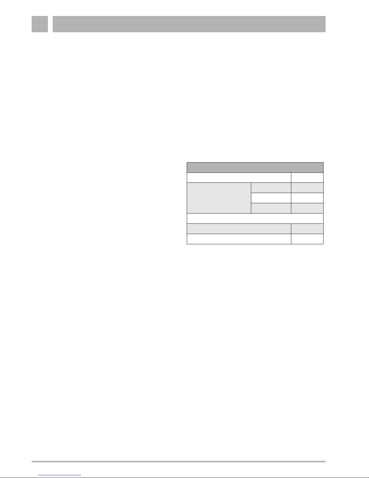
Maximum Temperature and Pressure Ratings:
Permissible Fuels:
Logano SB735: Fuel Natural Gas or L.P
Please observe the guidelines of the gas supply
company!
Maximum Temperature and Pressure Ratings
Maximum Supply Temperature: 210 °F
Allowed System Pressure
(Models)
790 43.5 psi
970 43.5 psi
1200 43.5 psi
Maximum Time constant:
- Manual Reset High Limit 40 sec
- Adjustable High Limit 40 sec
Table. 1 Maximum Temperature and Pressure Ratings

Packaging and Components 2
5
We reserve the right to make any changes due to technical modifications!
Boiler Installation and Maintenance Manual SB735 • Issue 10/2003
Buderus Heiztechnik GmbH • http://www.heiztechnik.buderus.de
2 Packaging and Components
The complete product is shipped in the following
components:
– Boiler vessel, bolted on transport woods
– Supply manifold, packaged with hydronic control
package
– Technical documentation, secured to the boiler
– VE insulation rings for burner and PVC condensate
drain (Siphon) secured to the boiler
– Boiler jacket panels and installation components,
packaged in a wooden crate and cardboard. The
assembly components are located in Pack A.
– The insulation blankets are packaged in 2 plastic
bags.
– A sound attenuating boiler base is supplied standard
with the SB735/1200 model.
– Electronic control panel, in cardboard box (optional).
– A condensate neutralization package can be ordered
separately.
– Hydronic control package, consisting of aquastat,
low water cut-off, relief valve and temperature
pressure gauge (when ordered from Buderus).
– Gas burner and gas train components, if ordered
from Buderus.
– Pre-cut burner mounting plate, if ordered from
Buderus.
Above mentioned components may differ slightly based
on the particular boiler model.
Technical Data, Dimensions and Water Connections3
6
We reserve the right to make any changes due to technical modifications!
Boiler Installation and Maintenance Manual SB735 • Issue 10/2003
Buderus Heiztechnik GmbH • http://www.heiztechnik.buderus.de
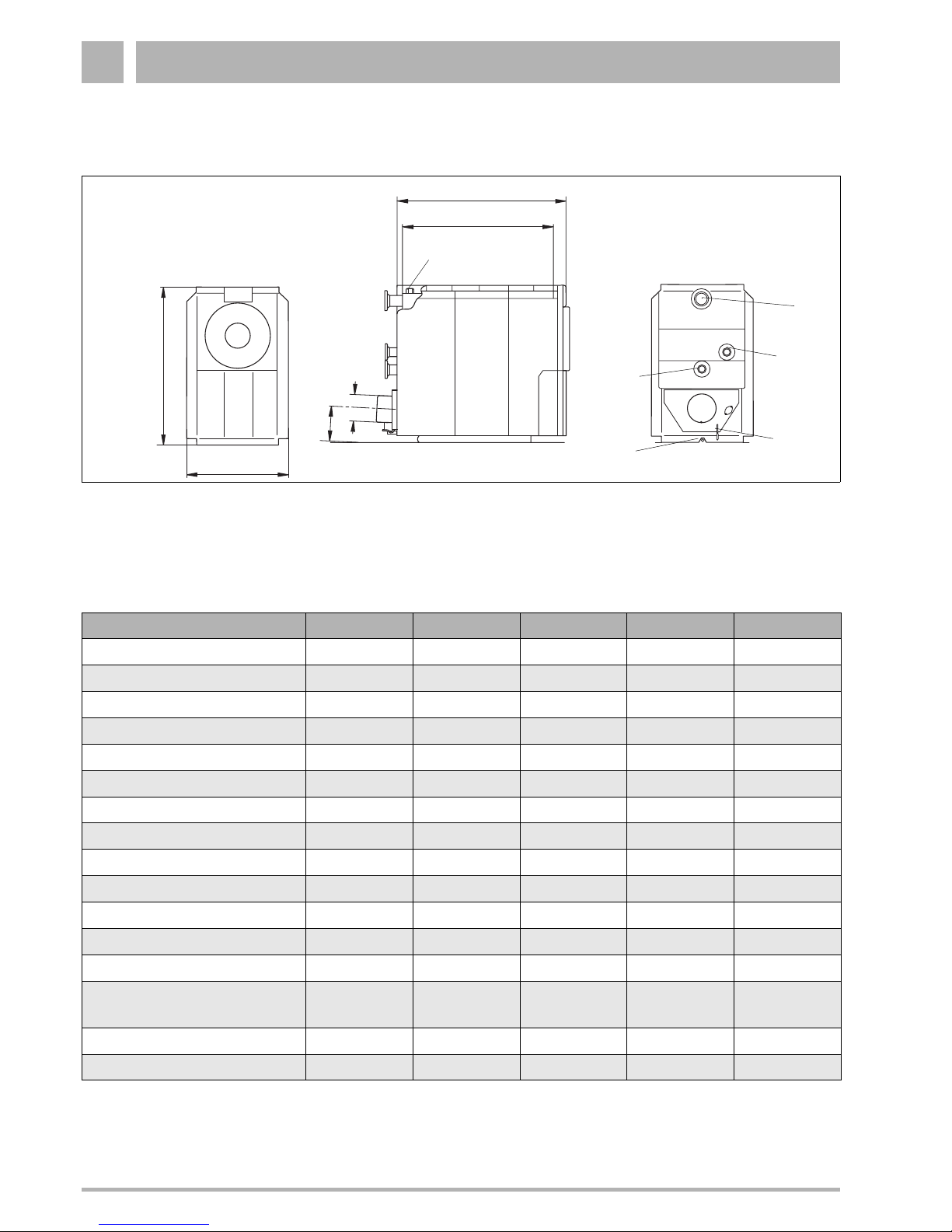
3 Technical Data, Dimensions and Water Connections
Fig. 1 Technical Data, Dimensions and Water Connections
VK = Boiler Supply Connection
RK1 = Low Temperature Return Connection
RK2 = High Temperature Return Connection
H* = Boiler Height with Logamatic 2107/2109=H+6 inch
AKO = Condensate Drain
EK = Water Feed
EL = Boiler Drain
M = Sensing Port for Temperature Sensor
Ø AA = Vent Pipe Diameter
L
L
K
H
B
H
AA
Ø AA
M
VK
RK
2
AKO
RK
1
EK/EL
Boiler Model 790 970 1200
Max. Input [MBH] 2751 3378 4179
Max. Output [MBH] 2605 3251 4079
IBR Net [MBH] 2265 2827 3547
Thermal Efficiency [%] 96.9 96.3 97.6
Combustion Efficiency [%] 94.7 95.6 96.5
Length L Inch 91 ½ 108 ¼ 108 ¼
Length L
K
Inch 75 ½ 92 92
Hight H Inch 81 ¼ 81 ¼ 81 ¼
Width BInch545454
Boiler Widthless Jacket Inch 44 ¼ 44 ¼ 46 ¼
Vent Connection-Ø inside Ø AA Inch 14 14 14
Vent Height H
AA
Inch 19 19 19
Weight Lbs. 4330 5441 5534
Boiler supply
1. First Return Connection
VK
RK
1
Inch
Inch
4
4
5
5
5
5
2. Second Return Connection RK
2
Inch 3 4 4
Boiler Drain/Water Feed EK/EL Inch 1½ 1½ 1½
Table. 2 Technical Data, Dimensions and Water Connections
Boiler Installation 4
7
We reserve the right to make any changes due to technical modifications!
Boiler Installation and Maintenance Manual SB735 • Issue 10/2003
Buderus Heiztechnik GmbH • http://www.heiztechnik.buderus.de
4 Boiler Installation
It is required to have a floor drain available near the
boiler.
It is recommended to place the boiler on solid foundation
of 2" to 4 " height. Use dimension B and L (Table 3) to
size this foundation.
The supporting floor must be level and of sufficient
strength.
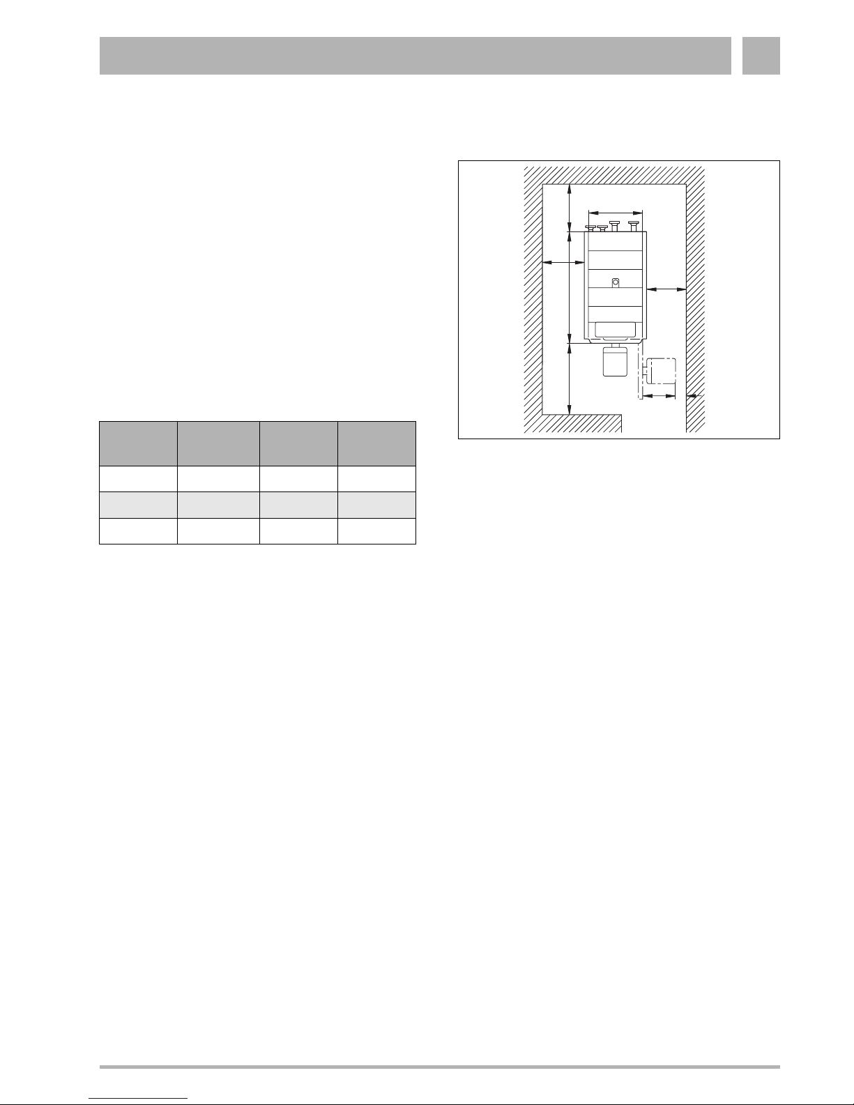
Observe the indicated side clearances when placing the
boiler (Fig. 2). Dimensions shown indicate minimum
clearances to combustibles or space needed to swing
open burner door.
Place the boiler horizontally on the supporting
foundation.
JNOTICE!
Make sure to install the base supplied with the
SB735/1200.
Fig. 2 Clearance dimensions for SB735 boilers
Boiler
Model
L
[Inch]
BK
[Inch]
A
[Inch]
790 91 43 ¾ 98“(43“)*
970 107 ½ 43 ¾ 98“(43“)*
1200 107 ½ 46 98“(43“)*
Table. 3 Minimum Boiler Pad
Please observe the burner length L
Br
with respect to the front
clearance.
AL
8“
32“
1)
L
Br
(0)
B
k
(4“)
(40“)
Anti-Vibration Supports5
8
We reserve the right to make any changes due to technical modifications!
Boiler Installation and Maintenance Manual SB735 • Issue 10/2003
Buderus Heiztechnik GmbH • http://www.heiztechnik.buderus.de
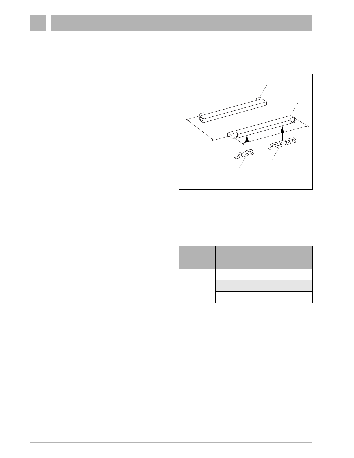
5 Anti-Vibration Supports
z Anti-vibration supports are standard equipment on
the SB735/1200 model; they can be ordered
separately for the other models.
z Insert the longer part of the longitudinal anti-vibration
bracket (Fig. 3, Item. 4) from the front and the
shorter part (Fig. 3, Item. 3) from the rear into the
channel sections (Fig. 3, Item. 2).
z Position both rails of the anti-vibration boiler support,
in accordance with dimensions shown in Table 4, on
the floor where the boiler is to be installed.
JNOTICE!
Prepare the foundation, where the anti-vibration
supports are to be located, with a smooth trowel
of ±1/8“ per linear foot and with a slight rise to
the back. This ensures an even load distribution
over the longitudinal anti-vibration brackets,
and adequate boiler ventilation.
z Position, align and place the boiler on the supports.
The boiler support should be flush with the boiler
back wall. The end-stop plates (Fig. 3, Item. 1)
should contact the channel section of the boiler.
Fig. 3 Anti-vibration support
Item. 1: End-stop plates
Item. 2: Channel section
Item. 3: Short anti-vibration bracket
Item. 4: Long anti-vibration bracket
Table. 4 Support dimensions
1)
Standard delivery
2)
Accessories
Boiler
Type
Boiler-
Model
Length
F
[Inch]
Distance
C
[Inch]
1200
1)
90 46
SB735
970
2)
90 43 ¾
790
2)
73 ½ 44
F
C
2
4
3
1
Boiler Assembly 6
9
We reserve the right to make any changes due to technical modifications!
Boiler Installation and Maintenance Manual SB735 • Issue 10/2003
Buderus Heiztechnik GmbH • http://www.heiztechnik.buderus.de
6 Boiler Assembly
JNOTICE!
Make sure, that when fitting the front thermal
insulation, the burner door of the combustion
chamber is closed, to prevent damage to the
stainless steel combustion chamber from
welding or grinding activities.
Order of installation:
1. Thermal insulation/Pack A
2. Pack B
3. Pack C
6.1 Installation of the Thermal Insulation
and Jacket Panels
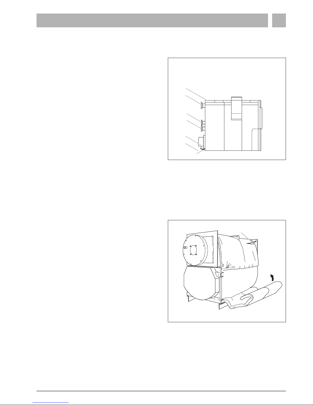
JNOTICE!
Ensure that the fabric is on the outside when
fitting the insulation blankets.
z Position the insulation blankets for the boiler body so
that the cut-outs are located over the cross brackets
plates (Fig. 5, Item. 1).
JNOTICE!
Position the narrow insulation blanket for boiler
model 790 at the rear, and note the drain cutouts.
JNOTICE!
Note the cut-outs for the low water indicator and
the cross bracket holder
(Fig. 7, Item. 1 + 5)!
z Position the front insulation blanket with its cut-out,
over the cross bracket holder.
z Tuck the insulation blanket in underneath the boiler
(Fig. 5).
Fig. 4 Connections
M = Sensing port for temperature sensor
VK = Boiler supply and relief valve connection
RK2 = High temperature boiler return
RK1 = Low temperature boiler return
AA = Vent connection
AKO = Condensate drain
EK/EL = Water feed/boiler drain
Fig. 5 Insulation blanket
M
VK
RK2
RK1
AA
AKO
EK/EL
1
Boiler Assembly6
10
We reserve the right to make any changes due to technical modifications!
Boiler Installation and Maintenance Manual SB735 • Issue 10/2003
Buderus Heiztechnik GmbH • http://www.heiztechnik.buderus.de
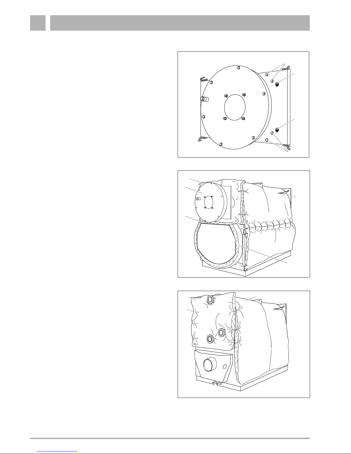
z Overlap the insulation blankets on the side and wrap
around the boiler body, then fasten with 8 clips.
z Unscrew four hexagon bolts (Fig. 6, Item. 1) from the
right side of the boiler door (Fig. 7, Item. 1) and four
from the left side.
ADANGER OF INJURY!
through falling parts.
Ensure that the hinge bolts (Fig. 21, Item. 1)
are in the boiler door before opening it.
JNOTICE!
The recesses (Fig. 6, Item. 2) in the boiler door
(2 on the left and 2 on the right side) have been
provided for lifting with a crane or hoist, for
example for the complete removal of the door.
z Open the burner door (Fig. 7, Item. 1)
z Place the insulation blanket with round cut-out
(Fig. 7, Item. 2), with its wide edge facing upwards,
on the left front of the boiler body (wide edge up) and
secure with four clips (2 left, 2 right) on the
surrounding thermal insulation.
ACAUTION!
Ensure that the wide edge is at the top at the
hinge bolts!
z Close the burner door and re-secure with eight
hexagon bolts.
z Position the thermal insulation strip (Fig. 7, Item. 3)
laminated on the front of the reversing door.
z Position the thermal insulation strips (Fig. 7, Item. 4)
for the reversing door from below around the side of
the reversing door and secure with two clips.
JNOTICE!
Observe the hinge bolt cut-outs!
z Locate the rear side thermal insulation (Fig. 8,
Item. 2) in accordance with the cut-outs on the rear
side of the boiler and secure with six clips (Fig. 8,
Item. 1, 3 left and 3 right) on the surrounding thermal
insulation (Fig. 8, Item. 3).
Fig. 6 Screws for opening the burner door
Fig. 7 Burner door insulation blanket
Fig. 8 Rear side insulation blanket
1
1
2
2
1
2
3
4
5
1
2
3

Boiler Assembly 6
11
We reserve the right to make any changes due to technical modifications!
Boiler Installation and Maintenance Manual SB735 • Issue 10/2003
Buderus Heiztechnik GmbH • http://www.heiztechnik.buderus.de
6.2 Boiler Jacket - Pack A
z Locate the front cross bracket (trapezoidal cut-out
down) with its two top holes on the threaded studs
and secure with nuts (Fig. 9).
z Locate the rear cross bracket (V-shaped cut-out
down) with its two top holes on the threaded studs
and secure with nuts (Fig. 9).
JNOTICE!
The edge of the cross bracket must point
outwards (Fig. 9).
z Insert the insulation blanket from the burner door
(Fig. 7, Item. 2) and the rear side (Fig. 8, Item. 2) into
the upper edge and the front and rear cross bracket.
z Lightly insert two screws M8 x 80 (Fig. 10, Item. 3)
from the top into the central cross bracket (Fig. 10,
Item.1).
z Secure the central gross bracket (Fig. 10, Item. 1) at
the top to the fixing bracket using two bolts, washers
and nuts (Fig. 10, Item. 2).
JNOTICE!
Ensure that the edge of the central cross
bracket (Fig. 10, Item. 1) points forward.
z Lightly secure the central cross bracket front (Fig. 9,
Item.1) on the left and the right side using two bolts
and washers.
JNOTICE!
Initially secure the central cross bracket (Fig. 9,
Item. 1) only lightly. Tighten the cross brackets
after they have been aligned and secured to the
side wall closest to the front.
z Push the strain relief (Fig. 10, Item. 4) on the hinge
side of the burner door into the cross bracket.
z Secure the strain relief with two bolts (Fig. 10).
Fig. 9 Cross brackets
Fig. 10 Strain relief
Item. 1: Central cross bracket
Item. 2: Fixing bracket
Item. 3: M8 x 80 bolts
Item. 4: Strain relief
Item. 5: Bolt location central cross bracket for boiler models
790 and 970
Item. 6: Bolt location central cross bracket for boiler model
1200
1
1
1 2
3
4
5
6
3

Boiler Assembly6
12
We reserve the right to make any changes due to technical modifications!
Boiler Installation and Maintenance Manual SB735 • Issue 10/2003
Buderus Heiztechnik GmbH • http://www.heiztechnik.buderus.de
z The horizontal brackets (L-brackets) comprise of two
components, which must be pre-assembled.
Join both bracket components with two bolts and two
nuts (Fig. 11).
z Hook the first bracket (Fig. 12, Item. 1) with the
U-shaped edge into the respective recess of the
front, center and rear cross brackets.
z The bracket is secured at the front hole and the rear
slot using one self-tapping screw each (Fig. 12).
z Hook the second bracket (Fig. 12, Item. 3) with the
U-shaped edge into the respective recess of the
front, centre and rear cross brackets.
z The bracket is secured at the front hole and the rear
slot using one self-tapping screw each (Fig. 12).
z Align the central cross bracket horizontally.
Fig. 11 Longitudinal (L-)bracket
Fig. 12 Secure the longitudinal bracket with bolts suppplied
Item. 1: Horizontal bracket
Item. 2: Central cross bracket
Item. 3: Horizontal bracket
1
2
3

Boiler Assembly 6
13
We reserve the right to make any changes due to technical modifications!
Boiler Installation and Maintenance Manual SB735 • Issue 10/2003
Buderus Heiztechnik GmbH • http://www.heiztechnik.buderus.de
Fig. 13 Bottom cross brackets (top view)
z Secure the lower front cross brackets (Fig. 13, Item.
3) to the boiler body using two bolts.
z Secure the lower rear cross bracket (Fig. 13, Item. 1)
to the boiler body using two bolts.
z Secure the left and right spacer plates (Fig. 13,
Item. 5) to the lower cross bracket using three bolts
and washers each (Fig. 13, Item. 6).
Use the holes Item. a for boiler models 790 and 970.
Use the holes Item. b for boiler model 1200.
z The lateral blue covers (Fig. 13, Item. 2) comprise
two components, which must be pre.assembled
(Fig. 13, Item. c: screw position for model 790 and
Item. d: screw position for models 970 and 1200).
Hook-in both covers centrally behind the bracket and
align horizontally, then join both pieces with two bolts.
z Secure the left and right side of the cover (Fig. 13,
Item. 2) to the front and rear using one bolt each.
z Secure the blue cover (Fig. 13, Item. 4) at the left and
right front of the cover (Fig. 13, Item. 2) using two
bolts respectively.
Item. 1: Rear cross bracket
Item. 2: Lateral covers
Item. 3: Front cross bracket
Item. 4: Front cross bracket cover
Item. 5: Spacer plate
Item. 6: Position of bolts on the spacer plate for boiler
models 790 and 970 and 1200 (top view)
Pos. a: Position of bolts on the spacer plate for boiler
models 790 and 970 (top view)
Pos. b: Position of bolts on the spacer plate for boiler model
1200 (top view)
Pos. c: Position of the bolts on the lateral blue covers for
boiler models 790 and 970 (side view)
Pos. d: Position of the bolts on the lateral blue covers for
boiler model 1200 (side view)
1
2
3
4
2
4
5
5
6
6
6
c
b
2
5
a
d

Boiler Assembly6
14
We reserve the right to make any changes due to technical modifications!
Boiler Installation and Maintenance Manual SB735 • Issue 10/2003
Buderus Heiztechnik GmbH • http://www.heiztechnik.buderus.de
z Hook the rear and central side walls at the bottom
into the edge between the cover and the spacer plate
(Fig. 14).
JNOTICE!
Note the recesses (Fig. 14, Item. 1) in the side
walls:
- Rear side wall 1 recess
(towards the central side wall).
- Central side wall 2 recesses.
- Side wall nearest the front 1 recess (towards
the central side wall).
z Lift the side walls and hook the top into edge of the
horizontal brackets (Fig. 15).
z Push the side walls back.
z Push the ends of the insulation blankets behind the
side wall edge.
z Insert the small side sections (Fig. 15, Item. 3) into
the side and at the bottom.
z Secure the side wall nearest the front to the central
cross brackets using one self-tapping screw (Fig. 15,
Item. 2) and secure the central cross bracket.
z Secure the small side sections (Fig. 15, Item. 3) at
the front using two self-tapping screws each (Fig. 15,
Item.1).
z Align the side wall position with bolts Fig. 12.
JNOTICE!
Remove the smaller side sections before
opening the lower reversing door.
Fig. 14 Hooking in the side walls at the bottom
Fig. 15 Hooking in the side walls at the top
Item. 1: Self-tapping screw for the small side section
Item. 2: Self-tapping screw for the side wall nearest the front
Item. 3: Smaller side section
1
1
2
4

Boiler Assembly 6
15
We reserve the right to make any changes due to technical modifications!
Boiler Installation and Maintenance Manual SB735 • Issue 10/2003
Buderus Heiztechnik GmbH • http://www.heiztechnik.buderus.de
6.3 Boiler Jacket - Pack B
z Position the front boiler cover (Fig. 16, Item. 1) on
top of the side wall edge and pull forward, until the left
and right hooks lock into the slots.
z Secure the front boiler cover by means of two self-
tapping screws (Fig. 16, Item. 2), which should be
inserted through the boiler cover brackets and the
side wall edge into the horizontal bracket.
Fig. 16 Install the boiler front cover
1
2

Boiler Assembly6
16
We reserve the right to make any changes due to technical modifications!
Boiler Installation and Maintenance Manual SB735 • Issue 10/2003
Buderus Heiztechnik GmbH • http://www.heiztechnik.buderus.de
6.4 Installation of the Control Panel
and Sensor Well
The optional Buderus control panel „Logamatic“ is
secured by fixing two hooks into the two holes in the
front top cover.
Control panel „Logamatic“ 2000 series
z Unscrew both self-tapping screws from the top out of
the terminal cover and remove the cover (Fig. 17).
z Route the capillary tubes through the cable raceway
and unroll to the required length.
z Locate the control panel so that the insert hooks are
inserted at the front into the oval holes, pull the
control panel forward and then tilt it back, until both
resilient hooks snap into place on the right and left
side (arrows Fig. 17).
z Secure the control panel to the front top cover on left
and right inside in the cable raceway using two selftapping screws.
JNOTICE!
If necessary, break or cut out the knock-out
from the rear wall of the control panel (Fig. 18).
Make all electrical connections in accordance with the
wiring diagram and local code requirements.
z Insert cable clips into the clip frame and secure by
pivoting the lever (Fig. 18).
z Insert both lower hooks on the right and the left side
of the rear wall section into the clip frame, keeping
the slot in the upper edge (Fig. 18).
z Press both upper resilient sliding hooks slightly
inwards (arrows on Fig. 18) and insert the rear wall
section so that both hooks lock into place.
z Locate the terminal cover and re-fit using the self-
tapping screws (Fig. 17).
JNOTICE!
Pay particular attention to the cable and
capillary runs! Do not kink the capillaries.
Connect the appliance with a permanent main
electrical disconnect!
Observe the local code requirements!
Fig. 17 Install the control panel
Fig. 18 Installation of the cable clips

Boiler Assembly 6
17
We reserve the right to make any changes due to technical modifications!
Boiler Installation and Maintenance Manual SB735 • Issue 10/2003
Buderus Heiztechnik GmbH • http://www.heiztechnik.buderus.de
z Install the well provided with the Logamatic control
into the M tapping.
z Route the capillary tubes with sensor to the sensor
well (Fig. 19).
z Insert the sensor into the sensor well, until it bottoms
out (sensor well M, see page 6 in Fig. 1) (Fig. 19).
z During the insertion, the plastic spiral (Fig. 20,
Item. 2) holding the sensor together slides back
automatically. To ensure a perfect contact between
the sensor well (Fig. 20, Item. 3) and the sensor
surfaces - thereby guaranteeing the safe
temperature transfer - push the compensating spring
(Fig. 20, Item. 1).
z Push the sensor holder (Fig. 20, Item. 4) from the
side or from above over the sensor well head.
Fig. 19 Sensor to the sensor well
Fig. 20 Capillary tubes with sensor and sensor well
Item. 1: Compensating spring
Item. 2: Plastic spiral
Item. 3: Sensor well
Item. 4: Sensor holder
M
1
2
3
4

Boiler Assembly6
18
We reserve the right to make any changes due to technical modifications!
Boiler Installation and Maintenance Manual SB735 • Issue 10/2003
Buderus Heiztechnik GmbH • http://www.heiztechnik.buderus.de
6.5 Burner Door and Burner
The burner door can be installed to swing to the left or
right.
ADANGER!
through falling parts.
Change the door opening only when the door is
closed and bolted.
JNOTICE!
The recesses (Fig. 21, Item. 2) in the boiler
door (2 left and 2 right) have been provided for
lifting with a crane or hoist, for example for the
complete removal of the door.
z Push the hinge bolts (Fig. 21, Item. 1) out from the
bottom through the top.
z Insert both hinge bolts with washers on the opposite
side (Fig. 21).
Do not forget to use the washers!
Observe the burner manufacturer’s installation
instructions!
Use or modify (drilled burner plate - accessory) the
appropriate burner plate subject to burner make and
type.
JNOTIVCE!
Seal the gap between the blast tube (Fig. 22,
Item. 2) and the thermal insulation (Fig. 22,
Item. 1) on site using the insulation rings
supplied (Fig. 22, Item. 3)! Cut insulation rings
to required dimensions.
Fig. 21 Burner door
Fig. 22 Burner installation
Item. 1: Thermal insualtion
Item. 2: Blast tube
Item. 3: Insulation rings
1
1
2
2
8 ¼
1
2
3

Boiler Assembly 6
19
We reserve the right to make any changes due to technical modifications!
Boiler Installation and Maintenance Manual SB735 • Issue 10/2003
Buderus Heiztechnik GmbH • http://www.heiztechnik.buderus.de
6.6 Boiler Jacket - Top Covers
z Locate the boiler top cover sections Fig. 23 with the
edges facing forward loosely onto the left and right
side walls.
z Push the boiler top cover sections forward.
JNOTICE!
The third top cover section provides a cut-out
(Fig. 23, Item. 3) for the low water indicator.
Cover the cut-out with a cover plate.
Table. 5 Dimensions of boiler top cover sections from Fig. 23,
Item. 1 to 5 (all dimensions in inches)
z Align and tightly secure the cross bracket.
z Insert the thermal insulation into the lower front wall
(Fig. 24, Item. 1).
z Hook the lower front wall with four offset hooks onto
the slots of the side wall edge (Fig. 24).
z Hook the offset brackets of the top front wall (Fig. 24,
Item. 2) into the slots of the lower front wall edge and
at the top into edge of the front top cover.
JNOTICE!
If the front wall can only be located with some
difficulties, re-align the central cross bracket.
z Hook the upper (Fig. 25, Item. 3) and the lower cover
part (Fig. 25, Item. 2) into the front wall sections
using the hook provided.
z Secure the rating tag plate to the side panel (Fig. 25).
6.7 Rating Tag Plate
z Affix the rating tag plate (Fig. 25, Item. 1) according
to the boiler location on the left or right side wall.
Fig. 23 Top cover sections
Fig. 24 Front cover panels
Fig. 25 Inserting front cover panels
Boiler
model
Item 1Item 2Item 3Item 4Item
5
790 17
¾ 17¾ 17¾ 11¼ 11¼
970 17¾ 17¾ 17¾ 19½ 19½
1200 17¾ 17¾ 17¾ 19½ 19½
1
2
3
4
5
1
2
2
hakghah
hakghah
hakg
1
3
2

Boiler Assembly6
20
We reserve the right to make any changes due to technical modifications!
Boiler Installation and Maintenance Manual SB735 • Issue 10/2003
Buderus Heiztechnik GmbH • http://www.heiztechnik.buderus.de
6.8 Boiler Jacket - Pack C
JNOTICE!
The rear wall consists of seven parts (Fig. 26).
z Secure the rear wall section (Fig. 26, Item. 1) with
two self-tapping screws per side (left and right) on the
side wall edges.
z Secure the small central rear wall section (Fig. 26,
Item. 6) on the lower rear wall section (edge pointing
inwards) using two self-tapping screws (Fig. 26,
Item. 1).
z Locate the central rear wall section (Fig. 26, Item. 2)
with the Z-profile behind the lower rear wall section
on the edge of the side wall and secure on the left
and right side with two self-tapping screws each.
z Insert the upper rear wall section (Fig. 26, Item. 3)
with Z-profile behind the central rear wall section on
the edge of the side wall, and secure on the left and
right side with two self-tapping screws each.
z Hook the upper small rear wall section (Fig. 26,
Item. 4) with the bracket into the upper rear wall
section, and secure with a self-tapping screw.
z Secure one or two cable clips (Fig. 26, Item. 5) or a
cable duct on the upper rear wall section.
z Secure the left and right locking plate (Fig. 26,
Item. 7) on the side wall using two self-tapping
screws respectively.
Fig. 26 installation of the rear wall section
Item. 1: Lower rear wall section
Item. 2: Central rear wall section
Item. 3: Upper rear wall section
Item. 4: Upper small rear wall section
Item. 5: Cable clip
Item. 6: Central small rear wall section
Item. 7: Left and right locking plate
7
1
2
3
4
6
5

Boiler Assembly 6
21
We reserve the right to make any changes due to technical modifications!
Boiler Installation and Maintenance Manual SB735 • Issue 10/2003
Buderus Heiztechnik GmbH • http://www.heiztechnik.buderus.de
6.9 Venting System
z The resulting combustion products must be
transported through a chimney system to the outside.
z It is required to use venting systems approved for use
with condensing, gas-fired equipment.
z Prior to placing the boiler in operation, it is required
to verify compatibility between boiler and venting
system.
z Check the venting system for air tightness!
z Install the venting system per manufacturer's
instructions.
SB Boiler Venting Requirements
The SB Boiler is a category II or IV appliance and the
exhaust vent materials must be UL listed for use with a
category IV appliance: operating temperatures of up to
240° F, positive pressure, condensing flue gas service.
Currently, UL Listed vents of AL29-4C or 316L Stainless
steel and/or CPVC must be used with the SB Boiler.
Proper clearances to combustibles must be maintained
per UL and vent manufacturer.
UL, NFPA 211 and NFPA 54 (National Flue Gas Code
ANSI Z223.1) guidelines are often the basis for state
and local codes. Buderus Hydronic Systems
recommendations follow the guidelines of these
recognized agencies unless there are codes applicable
to the installation site that are more stringent. The
venting and combustion air systems must meet all
applicable code requirements.
Code Required Vent Terminations:
Horizontal Terminations:
z Vent terminations should be at least 4 feet below, 1
foot above or 4 feet horizontally from any window,
door or gravity air inlet of a building.
z The termination shall be at least 3 feet away from any
other building opening, gas utility meter, service
regulator or the like.
z The termination shall be at least 6 feet away from the
combustion air intake of any other appliance.
z The bottom of the vent terminal should be at least 12
inches above both finished grade and any snow
accumulation point.
z Vent should not terminate over public walkways or
over an area where condensate or vapor could
create a nuisance or be detrimental to the operation
of regulators, meters and other equipment.
z Discharges should not be in wind-blocked areas,
corners, or directly behind vegetation.
Vertical Terminations:
z Roof penetrations should follow all applicable codes
and the vent manufacturer's instructions. The vent
should never be installed at less than the required
clearances to combustible materials per UL, NFPA,
and local codes. "Double-wall or thimble" assemblies
are required when penetrating combustible walls and
roofs.
z Vertical discharges should extend at least 2 feet
above the roof through properly flashed penetrations
and at least 2 feet above anything within a 10 foot
horizontal diameter. Discharges that extend more
than 2 feet above the roof must be laterally
supported.
z If the vent system is to be connected to an existing
stack, the stack must be UL Listed for Category II or
IV appliances (capable of 240°F, positive pressure
and condensing flue gas operation).
z Masonry stacks must be lined and the vent
penetration must terminate flush with and be sealed
to this liner. Vents may enter the stack through the
bottom or side.
z SB Boilers vent systems must not be interconnected
to any other venting system; The SB Boiler is
designed to maintain its own vent system.
z The exhaust vent must be pitched up toward the
termination a minimum of ¼" in. per foot of length.
Condensate must flow back to the SB Boiler freely,
without accumulating in the vent.
Combustion Air from Outside the Building
If outside combustion air is required, the room shall have
two permanent louvered openings to the outdoors. Each
opening must have a minimum free area of 1 square
inch for each 4,000 Btu/hr of total input rating of all fuel
burning equipment in the space.
When the air is supplied to the room via ducts, two ducts
must be used. Vertical ducts and openings must have a
minimum free area of 1 square inch for each 4,000 Btuh
of the total input rating of all fuel burning equipment in
the space. Horizontal ducts and openings must have a
minimum free area of 1 square inch for each 2,000 Btuh
of the total input rating of all fuel burning equipment in
the space.
The free area of the openings must be taken into
account restrictions from the louvers and screens. The
louver manufacturer should be consulted for the
percentage of free area available. When free area is not
known, metal louvers typically have 60 - 70% of free
area, wooden louvers have between 20 - 25% of free
area. Louvers should be in a fixed position or interlocked
with equipment so that they open automatically during
equipment operation.

Boiler Assembly6
22
We reserve the right to make any changes due to technical modifications!
Boiler Installation and Maintenance Manual SB735 • Issue 10/2003
Buderus Heiztechnik GmbH • http://www.heiztechnik.buderus.de
The combustion air damper opening shall be located as
follows: top louver shall began within 12" of the ceiling
and the bottom louver within 12" of the floor as
prescribed in NFPA 54.
Combustion Air from an Adjacent Room
Where combustion air is to be used from within the
building, air must be provided into the equipment room
through two permanent openings into the interior
building. Each opening must have a minimum free area
of 1 square inch for each 1,000 Btuh of the total input
rating of all fuel burning equipment in the space. The
louvers shall be located as follows: top louver shall start
within 12" of the ceiling and the bottom louver within 12"
of the floor as prescribed in NFPA 54.
Exhaust Vent Systems
Positive-Pressure - The vent system is designed to be
under positive pressure at all firing rates. The minimum
vent size is 14" diameter. Horizontal vent pipe should be
supported at least every 6 feet and vertical vent should
be support to prevent excessive weight on the horizontal
runs.
AWARNING!
Use only an approved vent starter coupling and
approved vent pipe from the same
manufacturer for Buderus SB boilers. Do not
mix components from different systems. The
vent system could fail, causing flue gas spillage,
resulting in severe personal injury or death.
Permissible Equivalent Venting Length
Configurations for SB735 Boilers
ANOTICE!
Above lengths represent total equivalent vent
length combining horizontal and vertical runs
and any elbow. For each 45° elbow, deduct 4 ft,
for each 90° elbow, deduct 7 ft.
A positive breeching draft is not to exceed
positive + 0.2 Inches WC.
Condensate Removal
The exhaust vent pipe must be pitched at least ¼" per
foot of length back to the boiler. This will allow
condensate to drain back to the unit to be disposed. Low
spots in the venting where condensate may collect
should be avoided. A plastic hose or PVC drain pipe
may be used to remove discharge to a floor drain. Care
should be taken to avoid kinks and from raising the drain
line above the trap assembly. If the condensate must be
lifted above trap assembly to a drain, it should be drain
into a sump so that it can pump away to a drain.
Permissible Equivalent Venting Length
Configurations for SB735 Boilers
(in ft)
Model
Nom. Vent
Size
12“ 14“
790 14" 165 195
970 14“ 130 180
1200 14“ - 165
Table. 6 Maximum venting length for SB735 boilers

Boiler Assembly 6
23
We reserve the right to make any changes due to technical modifications!
Boiler Installation and Maintenance Manual SB735 • Issue 10/2003
Buderus Heiztechnik GmbH • http://www.heiztechnik.buderus.de
6.10 Neutralization Equipment and Water
Controls Installation
DNOTICE
Observe the separate installation instructions
for the installation and maintenance of the
neutralization system (part of the standard
delivery of the neutralisation system).
z Push the siphon delivered onto the pipe connector on
the flue gas collector and tighten the union nut on the
siphon.
z Connect the drain hose to the connector (Fig. 27,
Item. 1) of the condensate drain (Siphon) (Fig. 27,
Item. 2) using a hose clip. When using Ø 1
½“ pipe
remove the tee piece on the siphon with a saw.
JNOTICE!
Generally, the condensate should be routed to
the boiler via the flue pipe. Where this is
impracticable, use only stainless steel or plastic
tee pieces in the separate feed hose pipe.
z Secure furnished supply manifold and gasket to
upper water connection (VK connection in (Fig. 1,
page 6)).
z Install furnished relief valve in supply manifold and
pipe discharge full port to nearby floor drain.
z Install low water cut-off and aquastat (s) in available
¾“ manifold tappings.
z Install pressure and temperature gauge in ½“
tapping.
z Plug any unused tappings.
z Refer to section 6.4 when installing Logamatic
control. Plug sensor port M (Fig. 1, page 6) with
¾“
plug when not
using a Logamatic control.
JNOTICE!
Lower return connection RK1 (Fig. 1, page 6)
must always
be used for connecting heating
systems return. Connect coldest return zone(s)
to RK1 for maximum efficiency. Connect higher
temperature return zone(s) to RK2 (Fig. 1,
page 6) if called for by engineering firm / design.
If the RK2 connection is not
used, close it off
with a blanking flange.
Fig. 27 Condensate
Item. 1: Connection for a drain hose
Item. 2: Siphon
Item. 3: Clean-out cover
3
1
2

Placing the Boiler in Operation7
24
We reserve the right to make any changes due to technical modifications!
Boiler Installation and Maintenance Manual SB735 • Issue 10/2003
Buderus Heiztechnik GmbH • http://www.heiztechnik.buderus.de
7 Placing the Boiler in Operation
ADANGER!
due to combustion products.
Prior to placing the boiler in operation, put 3 or
4 gallons of water in the clean-out opening or
combustion chamber to fill the drain in the
condensate drain line (Fig. 27, Item. 3).
ABOILER DAMAGE!
due to corrosion and debris build-up.
Flush the entire heating system prior to firing the
boiler. To avoid corrosion and debris build-up
on the water side of the boiler. It is required to
test the fill and make-up water per Instructions
for Water Preparation for Boiler.
DNOTICE!
Observe the installation instructions for the
neutralization system!
Follow the instructions supplied with boiler,
burner, controls and low water cut-off
components during the start-up of the system.
Make the end user familiar with the function and
operation of the entire system and sign over the
technical documentation.
It is recommended to instruct the end user
regarding maintenance requirements and
procedures. An annual service contract is
recommended.

Maintenance 8
25
We reserve the right to make any changes due to technical modifications!
Boiler Installation and Maintenance Manual SB735 • Issue 10/2003
Buderus Heiztechnik GmbH • http://www.heiztechnik.buderus.de
8 Maintenance
8.1 General Information
ADANGER!
due to unauthorized service work.
Maintenance work on gas components can only
be carried out by a gas certified service
company.
JNOTICE!
The end user or operator is required to have
regular scheduled maintenance performed. An
annual maintenance procedure on the entire
system is required.
JNOTICE!
We recommend an annual service contract for
the maintenance.
The factory required maintenance steps are
outlined in the check list (see section 9 „Check
List“).
Follow the burner manufacturer’s instructions
regarding burner maintenance!
8.2 Cleaning of the Boiler
ADANGER!
due to incorrect boiler brushers.
Use only brushes made available through
Buderus Hydronic System, Inc..
HDANGER!
due to current carrying wires.
Prior to maintenance shut down the electrical
power supply and pad lock.
JNOTICE!
A high pressure washer is recommended for a
wet cleaning of the heat exchanger.
Boiler debris should not be sent through the
neutralization system.
Check to make sure the condensate drain does
not get plugged (Fig. 27, Item. 2.).

Maintenance8
26
We reserve the right to make any changes due to technical modifications!
Boiler Installation and Maintenance Manual SB735 • Issue 10/2003
Buderus Heiztechnik GmbH • http://www.heiztechnik.buderus.de
z Check and possibly clean the flue gas collector and
the condensate drain through the clean-out cover
(Fig. 27, Item. 3).
z Remove the upper (Fig. 28, Item. 4) and lower cover
part (Fig. 28, Item. 1).
z Remove the upper front wall (left and right) (Fig. 28,
Item. 3 und 5).
z Remove the lower front wall (Fig. 28, Item. 2).
z Remove the left and right side wall sections (Fig. 28,
Item. 6).
ADANGER!
through falling parts.
Ensure that the hinge bolts (Fig. 29, Item. 1 and
2) are in the boiler door and in the reversing
door, before opening the doors.
z Loosen the bolts on the reversing door (Fig. 29, Item.
1) and pivot the reversing door aside.
z Remove the hexagon bolts from the boiler door
(Fig. 29, Item. 2) and open the door.
z Clean the combustion chamber and the heating
surfaces.
z Brush out the secondary and third firetubes (Fig. 30).
JNOTICE!
When cleaning the secondary and third
firetubes, the entire brush head should protrude
from the firetube before the cleaning brush is
withdrawn again.
z Remove any cleaning residues with a vacuum
cleaner. Observe the opening instructions of the
cleaning equipment when cleaning by pressure
spray!
z Check the gaskets on the boiler door and the
reversing door and replace, if necessary.
ASYSTEM DAMAGE!
Spray must not enter into the control panel!
z Close and bolt down the boiler door.
z Close and bolt down the reversing door.
z Fit the insulation blanket.
z Install the side wall sections.
z Install the upper and lower front wall.
z Re-start the system.
Fig. 28 Remove the front wall
Fig. 29 Open the boiler door
Fig. 30 Cleaning the secondary and third firetubes
1
2
3
45
6
1
2

Check List 9
27
We reserve the right to make any changes due to technical modifications!
Boiler Installation and Maintenance Manual SB735 • Issue 10/2003
Buderus Heiztechnik GmbH • http://www.heiztechnik.buderus.de
9 Check List
Check off the different maintenance steps, place an „X”
in the corresponding box and list date and service
company name below.
Follow recommended time frame for boiler and burner
maintenance work.
Heating system 01 02 03 04 05 06 07 08
1 Disconnect electrical supply to system
2 Shut off gas supply
3 Disconnect gas supply from burner
4 Remove front jacket panels, open burner door
5 Remove reversing door
6 Remove condensate drain hose from neutralization
system
7 Check and clean combustion chamber
8 Check and clean out fire tube passages
9 Flush condensate drain connection at boiler
10 Check and clean flue collector
11 Check burner gasket, replace if necessary
12 Check gasket on reversing door, replace if
necessary
13 Reattach condensate drain hose
14 Close off the reversing cover, bolt down and as-
semble jacket panels
15 Pour 3 gal. of water into the combustion chamber
16 Close the burner door, bolt down and assemble ja-
cket panels
17 Reattach the gasline to the burner
18 Check the gasline for leaks and correct if necessary
19 Check venting system for leaks, repair when needed
20 Check operation of the safety controls
21 Check operation of all operating controls
22 Bring the system back into regular operation
23

Check List9
28
We reserve the right to make any changes due to technical modifications!
Boiler Installation and Maintenance Manual SB735 • Issue 10/2003
Buderus Heiztechnik GmbH • http://www.heiztechnik.buderus.de
Neutralization system 01 02 03 04 05 06 07 08
1 Isolate the neutralization system from the main
electricity supply
2 Disconnect the inlet and outlet hose from the
granulate container
3 Remove the container lid of the neutralization
system
4 Remove used granulate (the container can be filled
by 180°), clean out the container
5 Fill with fresh granulate (in accordance with
instructions)
6 Replace and, if necessary, bolt down the container
lid of the neutralization system
7 Plug-in the mains cable of the neutralization system
into a main socket
8 Reconnect all hose connections and check for leaks
9 Start-up the neutralization system
10
Specialist contractor
__________ 01
Date:
Specialist contractor
___________ 02
Date:
Specialist contractor
__________ 03
Date:
Specialist contractor
___________ 04
Date:
Specialist contractor
__________ 05
Date:
Specialist contractor
___________ 06
Date:
Specialist contractor
__________ 07
Date:
Specialist contractor
___________ 08
Date:

Check List 9
29
We reserve the right to make any changes due to technical modifications!
Boiler Installation and Maintenance Manual SB735 • Issue 10/2003
Buderus Heiztechnik GmbH • http://www.heiztechnik.buderus.de

Notes
We reserve the right to make any changes due to techical modifications! Buderus Heiztechnik GmbH • http://www.heiztechnik.buderus.de
Boiler Installation and Maintenance Manual SB735 • Issue 10/200330

31
Notes
We reserve the right to make any changes due to techical modifications! Buderus Heiztechnik GmbH • http://www.heiztechnik.buderus.de
Boiler Installation and Maintenance Manual SB735 • Issue 10/2003

BBT North America Corporation
50 Wentworth Avenue
Londonderry, NH 03053
Tel. 603-552-1100
Fax 603-584-1681
www.buderus.net
Products manufactured by
BBT Thermotechnik GmbH
D-35573 Wetzlar
www.buderus.de
BBT North America Corporation reserves the right
to make changes without notice due to continuing
engineering and technological advances.
 Loading...