

Page 1
For contractors
Read carefully prior
to installation and
maintenance.
Note:
This boiler must only be operated with
natural gas or liquid propane (LP)!
Installation and maintenance
instructions
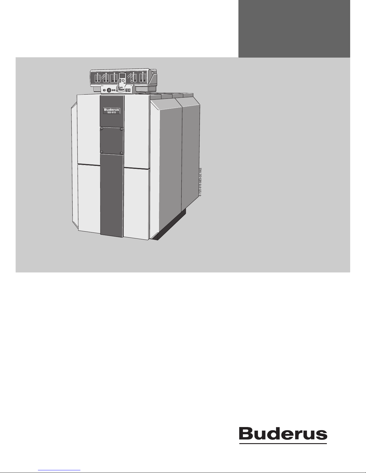
Gas fired condensing
boiler
Logano plus SB615 Gas
6 720 640 266 - 08/2009 GB/IE
Page 2
Contents
Logano plus SB615 Gas - We reserve the right to make any changes due to technical modifications.
2
Contents
1 Explanation of symbols and safety instructions . . 3
1.1 Symbols . . . . . . . . . . . . . . . . . . . . . . . . . . . . . . . . . . 3
1.2 Safety information . . . . . . . . . . . . . . . . . . . . . . . . . . 3
2 Information about the appliance . . . . . . . . . . . . . . . 5
2.1 EU Declaration of Conformity . . . . . . . . . . . . . . . . 5
2.2 Correct use . . . . . . . . . . . . . . . . . . . . . . . . . . . . . . . 5
2.3 Data plate . . . . . . . . . . . . . . . . . . . . . . . . . . . . . . . . 5
2.4 Standard delivery . . . . . . . . . . . . . . . . . . . . . . . . . . 5
2.5 Tools, materials and auxiliary equipment . . . . . . . 5
2.6 Specifications, dimensions, connections . . . . . . . 6
3 Regulations, standards and guidelines . . . . . . . . . . 9
3.1 Low water indicator installation . . . . . . . . . . . . . . . 9
3.2 Standards and guidelines/directives . . . . . . . . . . . 9
3.3 Leaks . . . . . . . . . . . . . . . . . . . . . . . . . . . . . . . . . . . 10
3.4 Safety limits . . . . . . . . . . . . . . . . . . . . . . . . . . . . . . 10
3.5 Boiler positioning . . . . . . . . . . . . . . . . . . . . . . . . . 11
3.5.1 Foundation and recommended wall clearances 11
3.5.2 Levelling the boiler . . . . . . . . . . . . . . . . . . . . . . . . 12
3.6 Disposal . . . . . . . . . . . . . . . . . . . . . . . . . . . . . . . . . 12
4 Transporting the boiler . . . . . . . . . . . . . . . . . . . . . . . 13
4.1 Means of transport . . . . . . . . . . . . . . . . . . . . . . . . 13
4.1.1 Transporting the boiler using a forklift truck . . . . 13
4.1.2 Transporting the boiler using two pallet trucks . 13
5 Installation of the boiler . . . . . . . . . . . . . . . . . . . . . . 14
5.1 Checking delivery for completeness . . . . . . . . . . 14
5.2 Disposing of packaging . . . . . . . . . . . . . . . . . . . . 14
5.3 Minimum clearances / product dimensions . . . . 14
5.4 Changing the hinging of the burner door . . . . . . 14
5.5 Installing the minimum pressure switch and
minimum pressure limiter . . . . . . . . . . . . . . . . . . 15
5.6 Low water indicator (accesory), fitting
(400 – 600kW) . . . . . . . . . . . . . . . . . . . . . . . . . . 15
5.7 Connecting the boiler to the pipework . . . . . . . . 16
5.7.1 Connecting the return to the boiler . . . . . . . . . . . 16
5.7.2 Connecting the flow to the boiler . . . . . . . . . . . . 16
5.7.3 Connecting the safety line flow . . . . . . . . . . . . . . 16
5.8 Filling the heating system and checking
connections for leaks . . . . . . . . . . . . . . . . . . . . . 17
5.9 Fitting the lagging . . . . . . . . . . . . . . . . . . . . . . . . . 18
5.10 Fitting the connection plates . . . . . . . . . . . . . . . . 19
5.11 Fitting the side panels . . . . . . . . . . . . . . . . . . . . . 20
5.12 Routing the burner cable . . . . . . . . . . . . . . . . . . . 21
5.13 Fitting the back plate . . . . . . . . . . . . . . . . . . . . . . 22
5.14 Fitting the front boiler cover . . . . . . . . . . . . . . . . . 23
5.15 Fit and connect the control unit (accessory) . . . 23
5.16 Installing the temperature sensor set . . . . . . . . . 25
5.17 Fitting the boiler cover sections . . . . . . . . . . . . . 26
5.18 Fitting the front panel . . . . . . . . . . . . . . . . . . . . . . 27
5.19 Securing the shield, device label
and data plate . . . . . . . . . . . . . . . . . . . . . . . . . . . . 28
5.20 Connecting and filling the neutraliser
(accesory) . . . . . . . . . . . . . . . . . . . . . . . . . . . . . . . 28
5.21 Installing condensate pipework . . . . . . . . . . . . . 29
5.22 Connecting the flue side of the heating system 30
5.22.1 General information on flue systems . . . . . . . . . 30
5.22.2 Fitting the flue pipe sealing collar (accessory) . 30
5.22.3 Fitting the flue temperature sensor (accessory) 30
5.23 Fitting burner (accessory) and connecting gas
supply . . . . . . . . . . . . . . . . . . . . . . . . . . . . . . . . . .31
5.23.1 Fitting the burner plate . . . . . . . . . . . . . . . . . . . . 31
5.23.2 Fitting the burner to the burner plate . . . . . . . . . 32
5.23.3 Connecting the gas supply . . . . . . . . . . . . . . . . . 33
6 Initial operation . . . . . . . . . . . . . . . . . . . . . . . . . . . . . . 34
6.1 Flushing the heating system . . . . . . . . . . . . . . . . 34
6.2 Filling the heating system . . . . . . . . . . . . . . . . . . 35
6.3 Preparing the heating system for operation . . . 36
6.4 Commissioning the control unit and the burner 36
6.5 Commissioning report . . . . . . . . . . . . . . . . . . . . . 37
7 Shutdown . . . . . . . . . . . . . . . . . . . . . . . . . . . . . . . . . . . 38
7.1 Shutting down the heating system . . . . . . . . . . 38
7.2 Shutting down the heating system in an
emergency . . . . . . . . . . . . . . . . . . . . . . . . . . . . . . 38
8 Inspection/maintenance . . . . . . . . . . . . . . . . . . . . . . 39
8.1 General notes . . . . . . . . . . . . . . . . . . . . . . . . . . . 39
8.2 Preparing the boiler for inspection and
maintenance . . . . . . . . . . . . . . . . . . . . . . . . . . . . .39
8.3 Cleaning the boiler . . . . . . . . . . . . . . . . . . . . . . . 40
8.4 Cleaning the flue gas collector . . . . . . . . . . . . . 42
8.5 Checking the heating system water pressure . . 43
8.6 Inspection and maintenance reports . . . . . . . . . 44
Page 3
1
Explanation of symbols and safety instructions
Logano plus SB615 Gas - We reserve the right to make any changes due to technical modifications.
3
1 Explanation of symbols and safety instructions
1.1 Symbols
Signal words indicate the hazard risk level resulting from
not following the instructions.
• Caution indicates that minor damage to property
could result.
• Warning indicates that minor personal injury or
serious material losses could result.
• Danger indicates that serious personal injury could
result. In particularly serious cases, lives could be at
risk.
Notes contain important information in cases where there
is no risk of personal injury or material losses.
1.2 Safety information
These installation and maintenance instructions contain
important information for the safe and appropriate
installation, commissioning and servicing of the Logano
plus SB615 Gas condensing boiler.
These installation and maintenance instructions are
designed for specialists, who, – through their vocational
training and experience, – are knowledgeable in handling
heating systems and gas installations.
Observe all standards and guidelines applicable to the
installation and operation of this system in your country.
Only use original Buderus spare parts. Losses caused by
the use of parts not supplied by Buderus are excluded
from the Buderus warranty.
Risk to life from gas explosion
There is a risk of explosion if you can smell gas!
B No open flames. Do not smoke. Do not use lighters.
B Prevent sparks. Do not operate electrical switches,
including telephones, plugs, door-bells, mobiles or
other electrical devices.
B Close the main gas shut-off valve.
B Open windows and doors.
B Warn all occupants of the building, but do not ring
doorbells.
B Do call your gas supplier from outside the building.
B If you hear gas escaping, immediately leave the
building, prevent others from entering and notify the
police and fire brigade from outside the building.
Customer information:
B Only qualified personnel may carry out the installation,
the main fuel and flue gas connections, the initial
start-up, electrical connections and any maintenance
or repair work.
B Work on gas-carrying equipment is to be carried out by
a licensed company.
Risk to life from poisoning
An insufficient supply of air can result in the escape of
dangerour flue gases!
B Prevent air inlet and outlet vents from becoming
blocked or restricted.
B Do not operate the boiler until any ventilation defects
have been rectified.
B Inform the system user in writing of the fault and its
associated dangers.
Safety information in the text is framed
and marked with a warning triangle on a grey
background.
Notes are identified by the symbol shown on
the left. They are bordered by horizontal lines
above and below the text.
Page 4

1
Explanation of symbols and safety instructions
Logano plus SB615 Gas - We reserve the right to make any changes due to technical modifications.
4
Risk of injury from electric shock
B Isolate the heating system from the mains electricity
supply before starting work. Use either an emergency
isolation switch or the relevant circuit breaker.
A contact separation of at least 3mm must be achieved
across EACH pole.
B Prevent unintentional reconnection of the electricty
supply.
Risk of fire from flammable materials or liquids
B Never store flammable materials or liquids in the
immediate vicinity of the boiler.
Laws and regulations
B The appliance must be installed in accordance with
and comply to, the current: Statutory Instrument Laws,
Gas Safety Regulations, IEE Regulations, Building
Regulations, Local Water By-Laws, Health & Safety
document 635 (The Electricity at Work Regulations)
and any other local requirements. Observe all
European and local installation standards, building
regulations and the latest edition of the wiring
regulations. Chemically aggressive substances, can
corrode the appliance and invalidate any warranty.
Preventative maintenance
B Carry out annual maintenance and cleaning
procedures. In the course of this work, check the entire
heating system (including neutralisation device) for
correct function.
B Have faults corrected as quickly as possible in order to
prevent system damage and to help protect your
heating system.
Frost protection
The heating system may freeze in cold weather if the
control unit is not turned on.
B Protect your heating system against frost when
temperatures below zero are expected. If for some
reason the control unit is to be switched off, drain the
system water from the boiler, DHW cylinder and all
heating system pipework.
System damage and personal injury due to
operator errors
Operator errors can result in injury and damage to
property.
B Ensure that children never operate this appliance
unsupervised or play with it.
B Ensure that only personnel who can operate this
appliance correctly have access to it.
Instructing the customer
B Hand these installation and maintenance instructions
to your customer when handing over the system.
Request that these instructions are kept in a safe
location next to the boiler.
B Explain to the customer how the appliance works and
how to operate it.
Page 5
2
Information about the appliance
Logano plus SB615 Gas - We reserve the right to make any changes due to technical modifications.
5
2 Information about the appliance
2.1 EU Declaration of Conformity
The design and operation of this product conform to
European Directives and the supplementary national
requirements. Its conformity is demonstrated by the CE
designation.
You can view the Declaration of Conformity on the
internet at www.buderus.de/konfo or request a copy from
your local Buderus sales office.
2.2 Correct use
The Logano plus SB615 Gas condensing boiler has been
designed for wet heating systems in e.g. multiple dwelling
units or in industrial applications. Any gas burner
type-tested to EN 676 can be used if its operating range
matches the boiler specifications.
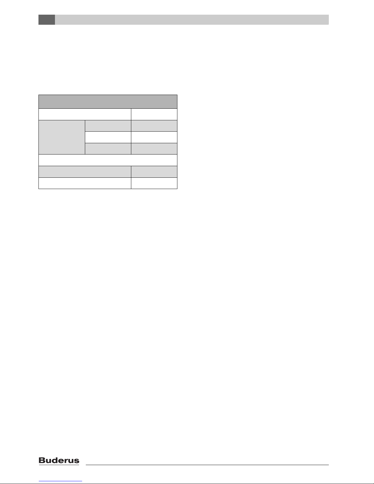
2.3 Data plate
2.4 Standard delivery
B Upon delivery, check all packaging for damage.
B Check the delivered package(s) for completeness.
• Boiler mounted on pallet
• Connection pipe for low water indicator, connected to
the boiler body (for boiler size ≥ 400 kW)
• Technical documents, attached to boiler block
• Siphon in the combustion chamber
• Boiler casing with thermal insulation and accessory
bag, packed in the wooden crate
• Control unit with wiring diagram and operating
instructions for electronic boiler and heating circuit
control, packed in carton (accessories ordered
separately).
• Neutralisation device, packed in individual carton
(accessory ordered separately)
It is possible that some of the standard accessories will
not be necessary for certain boiler types.
2.5 Tools, materials and auxiliary
equipment
For the installation and maintenance of the boiler, you
require standard tools, as used in space heating as well
as gas and water installations.
The information on the type plate is binding
and must be observed!
Page 6
2
Information about the appliance
Logano plus SB615 Gas - We reserve the right to make any changes due to technical modifications.
6
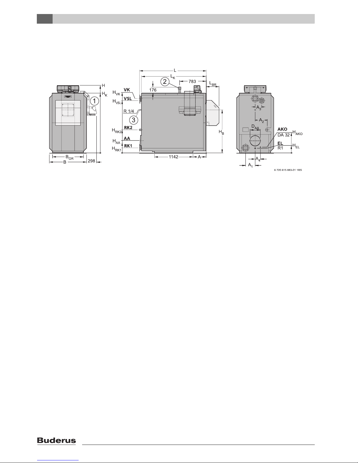
2.6 Specifications, dimensions, connections
The specification provides information on the output
profile of the Logano plus SB615 gas condensing boiler.
Fig. 1 Specifications, dimensions, connections
ØAAFlue pipe internal diamater
A Clearance
AKO Condensate outlet
B Boiler width incl. casing
B
GR
Base frame
DAAGas outlet
EL Cold water inlet/drain
H Boiler height including control unit, e.g. Logamatic
4311/12 control unit, = H + 235 mm
H
AA
Flue outlet height
HELDrain
HKBoiler height excl. control unit
L Boiler length incl. casing
L
BR
Burner length
LKBoiler block length
RK1 Boiler return 1
RK2 Boiler return 2
VK Boiler flow
VSL Flow safety line
1 Side-mounted control unit holder (left/right)
2 Spigot for low water indicator for boiler sizes 400 kW and
above
3 Minimum pressure monitor for boiler size 145 – 240 kW
or minimum pressure limiter for boiler size 310 kW as
accessory
Page 7
2
Information about the appliance
Logano plus SB615 Gas - We reserve the right to make any changes due to technical modifications.
7
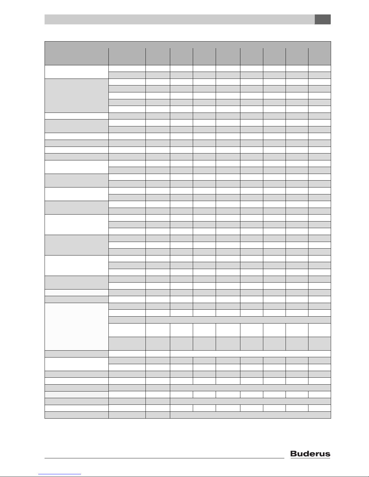
Specifications for Logano plus SB615 Gas
Boiler size Unit 145 185 2301)/240 310 400 510 640
Length
L mm 1816 1816 1845 1845 1845 1980 1980
L
K
mm 1746 1746 1774 1774 1774 1912 1912
Burner length
L
BR
- Logatop VM mm 376 376 376 376 – – –
L
BR
- WG mm 500 500 500 500 577 868 868
L
BR
- BS/M mm 280 301 – – – – –
L
BR
- RS/M mm – – 580 580 580 580 840
L
BR
- RS/M BLU mm – – – – – 840 –
Width
B mm 900 900 970 970 970 1100 1100
Height
H mm 1606 1606 1638 1638 1842 2000 2000
H
K
mm 1376 1376 1408 1408 1612 1770 1770
Width/height/ for transport mm 720/1340 720/1340 790/1370 790/1370 790/1570 920/1730 920/1730
Length mm 1735 1735 1760 1760 1760 1895 1895
Base frame B
GR
mm 720 720 790 790 790 920 920
Clearance A mm 285 285 285 285 285 367 367
Flue outlet
ØD
AA
inside DN 183 183 203 203 253 303 303
H
AA
mm 300 300 305 305 333 370 370
Combustion chamber
Length mm 1460 1460 1460 1460 1460 1594 1594
Ø mm 453 453 453 453 550 650 650
Burner door
Depth mm 185 185 185 185 185 185 185
H
B
mm 985 985 1017 1017 1135 1275 1275
Boiler flow
2)
ØVK DN656580 80100100100
H
VK
mm 1239 1239 1260 1260 1442 1613 1613
Boiler return 1
2)
Ø RK1 DN 65 65 80 80 100 100 100
H
RK1
mm 142 142 142 142 150 150 150
A
1
mm 275 275 300 300 290 284 284
Boiler return 2
2)
ØRK2 DN R 1½ R 1½ R 1½ 65 65 80 80
H
RK2
mm 495 495 512 512 597 685 685
A
2
mm 295 295 310 310 315 360 360
Flow, safety line
3)
Ø VSL DN R 1¼ R 1¼ 32 32 50 50 50
H
VSL
mm 1180 1180 1213 1213 1327 1549 1549
A
3
mm 160 160 170 170 210 195 195
Condensate outlet
H
AKO
mm 164 164 164 164 164 160 160
A
4
mm 100 100 120 120 140 155 155
Drain H
EL
mm 85 85 82 82 90 138 138
Logatop gas connection VM DN 1½ 1½ 1½ 2 – – –
Combustion heat output
of kW 54.3 69.3 89.8 116.0 149.5 191.6 239.9
up to kW 135.8 173.2 224.4 289.9 373.8 478.9 599.8
Logatop VM
Partial load
35% kW
47.5 60.6 75.3 101.5 – – –
Full load
kW
135.8 173.2 215 289.9 – – –
CO2 content % 10
Weight
net kg 613 620 685 705 953 1058 1079
With burner kg 648/643
1)
655/6501)720/7151)753/7351)1001 1156 1177
Water capacity l 560 555 675 645 680 865 845
Gas capacity l 327 333 347 376 541 735 750
Free draught Pa 501)/boiler-dependent4).
Hot gas resistance mbar 1.20 1.55 2.20 2.40 3.00 3.55 4.40
Permissible flow temperature
5)
°C 120
Permissible operating pressure bar 4 4 5 5 5.5 5.5 5.5
CE mark, boiler CE-0085 AT 0075
Tab. 1 Specification
Page 8
2
Information about the appliance
Logano plus SB615 Gas - We reserve the right to make any changes due to technical modifications.
8
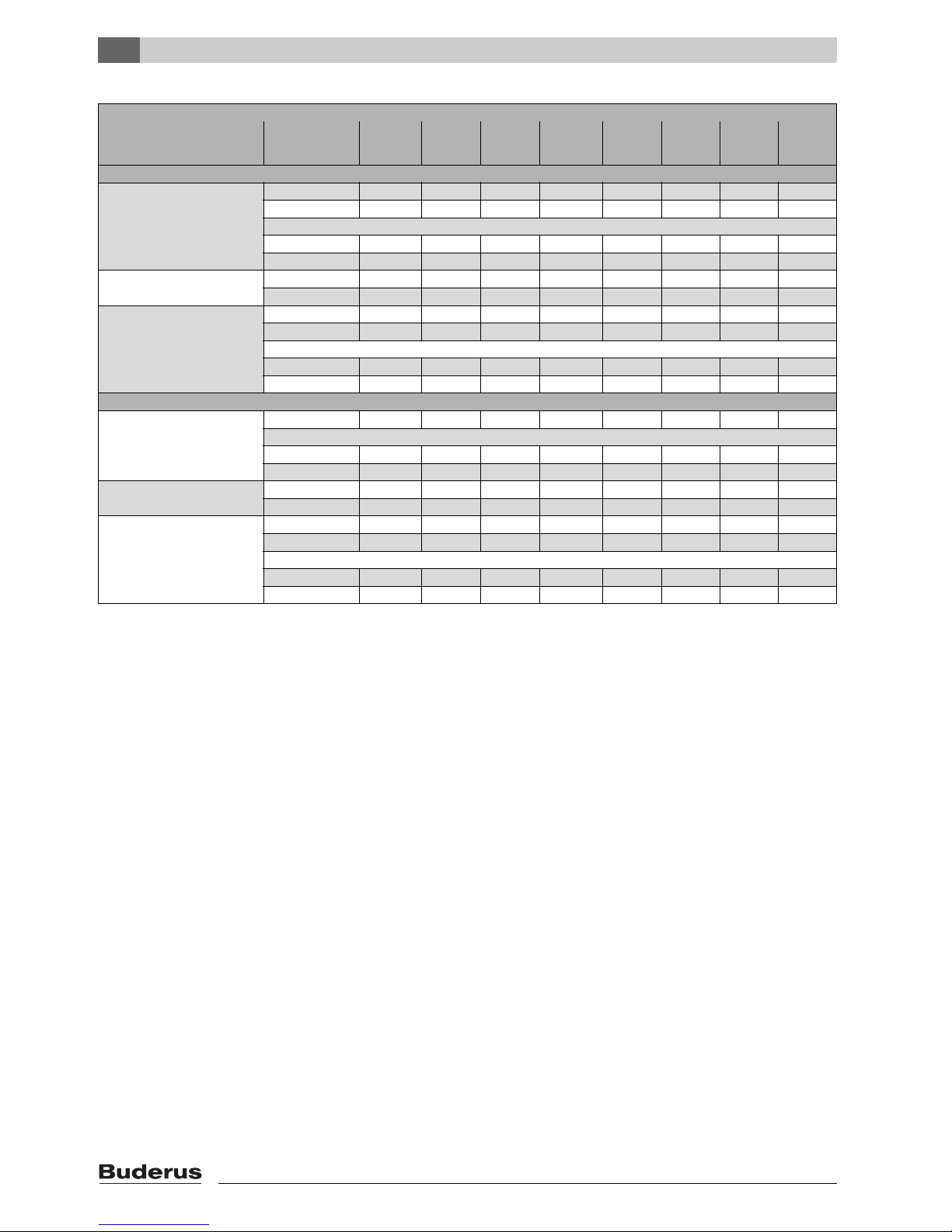
System temperatures 50/30 °C
Rated output
Full load kW 145 185 240 310 400 510 640
Partial load kW 59.2 75.6 97.8 126.3 162.4 208.8 261.5
Logatop VM
Full load kW 145 185 230 310 – – –
Partial load kW 51.8 66.1 82.1 110.6 – – –
Flue gas temperature
6)
Full load °C 40 40 46 46 42 44 44
Partial load °C 33 33 35 34 37 35 32
Flue gas mass flow rate
Full load kg/s 0.0552 0.0704 0.0928 0.1200 0.1528 0.1969 0.2466
Partial load kg/s 0.0217 0.0277 0.0360 0.0465 0.0603 0.0770 0.0958
Logatop VM
Full load kg/s 0.0633 0.0808 0.1010 0.1350 – – –
Partial load kg/s 0.0220 0.0283 0.0352 0.0474 – – –
System temperatures 80/60 °C
Rated output
Full load kW 132.7 169.2 218.9 282.8 365.2 467.9 585.4
Logatop VM
Full load kW 132.7 169.2 210.7 282.8 – – –
Partial load kW 50.6 64.5 80.2 108.1 – – –
Flue gas temp.
6)
Full load °C 66 66 71 71 68 69 71
Partial load °C 45 45 45 44 45 44 44
Flue gas mass flow rate
Full load kg/s 0.0579 0.0738 0.0956 0.1235 0.1592 0.2040 0.2555
Partial load kg/s 0.0231 0.0295 0.0383 0.0494 0.0637 0.0816 0.1022
Logatop VM
Full load kg/s 0.0633 0.0808 0.1010 0.1350 – – –
Partial load kg/s 0.0220 0.283 0.0352 0.0474 – – –
1) In conjunction with Logatop VM.
2) According to EN 1092-1 PN6
3) According to EN 1092-1 PN16
4) With Logano plus SB615 with third party burner
5) Safety limit (High limit safety cut-out). Max. possible flow temperature = safety limit (STB) – 18K.
Example: Safety limit (STB): 100 °C, max. possible flow temperature = 100 - 18 = 82 °C
6) To DIN EN 303. Minimum flue gas temperatures for chimney design calculations in accordance with EN 13394-1 Æ Technical Guide "Boiler
characteristic values for the dimensioning of flue gas systems".
Specifications for Logano plus SB615 Gas
Boiler size Unit 145 185 2301)/240 310 400 510 640
Tab. 1 Specification
Page 9
3
Regulations, standards and guidelines
Logano plus SB615 Gas - We reserve the right to make any changes due to technical modifications.
9
3 Regulations, standards and guidelines
During installation and operation of the system, standard
engineering practices, the buildings regulations and any
legislative requirements must be observed.
3.1 Low water indicator installation
B For boilers > 300 kW, install a low water indicator,
following the manufacturer's technical documents for
installation and operation.
B If the LWI connection provided is not used for the
installation of an SYR 932.1 low water indicator
(Buderus accessory), seal the connection off with a
plug (Æ Chapter 5.6, page 15).
The Logamatic control system is used for this boiler.
3.2 Standards and guidelines/directives
This device meets all basic requirements of relevant
European standards and guidelines:
• 90/396/EC Gas Appliance Directive
• EN 677, EN 303-1, EN 303-3, DIN 4702-6, EN 267,
EN 303-2
• 92/42/EC Efficiency Directive
• 2006/95/EC Low voltage Directive
• 2004/108/EC Electro Magnetic Compatibility
Directive
• 97/23/EC Pressure equipment Directive
Standard: TRD 702
Observe the following during installation and
operation:
• Local Building Regulations concerning boiler room
installations
• Local Building Regulations regarding air supply and
extraction equipment as well as connection to a flue
• Latest edition of the IEE Wiring regulations governing
electrical connection to the mains power supply
• The technical rules of the gas supply utility regarding
the connection of the gas burner to the local mains gas
supply
• Regulations and standards regarding the safety
equipment in water-filled heating systems
• Installation instructions for heating engineers
• In Belgium, the standards NBN D 30-003,
NBN D 51-004 and addenda must be observed.
• In the Netherlands, technical rules, building regulations
and other legal requirements (e.g. NEN 1078 (GAVO),
NEN 3028 and NEN 1010) must be observed when
installing and operating the system.
• In Austria, observe local building regulations as well as
ÖVGW Directive G1 or G2 (ÖVGW-TR gas or LPG)
during installation. The requirements of the national
directive Article 15a B-VG, regarding emissions and
efficiency, are fulfilled.
•For Switzerland:
By carrying out measurements at the installation
location, it must be checked whether the LRV maximum
permitted limits concerning CO and NOx are being
observed. The boilers have been tested according to
VKF fire safety regulations. During installation, observe
the guidelines for installing and operating gas-fired
boilers G3 d/f, the gas guidelines G1 SVGW, and local
fire safety regulations in force within the canton.
The output figures shown in the tab. "Specifications"
are nominal output figures.
In practice, these values will sometimes not be reached
within the specified output range in order to adhere to
LRV regulations.
Permissible fuels
Logano SB615 Gas and Logano plus SB615 VM gas
condensing boilers can be operated using the following
fuels:
• Natural gas and liquid propane (LP) according to
DVGW (German certification body) worksheet G 260
• Natural gas and liquid propane (LP) supplied by public
gas utility (Austria, Switzerland)
B Only use burners that are compatible with these gas
types.
B Observe the specifications of the burner supplier.
Observe all standards and guidelines
applicable to the installation and operation of
this system in your country!
The details on the boiler rating plate are
definitive and must be observed.
For UK & Ireland:
B For boilers > 300 kW, install a low water
indicator as required by BS-EN 12828.
B For installation and operation, refer to the
technical documents provided by the
manufacturer.
For Poland:
B For boilers > 100 kW, equip the boiler
with a low water indicator as required by
PN-91/B-2414 (p2.5).
Page 10
3
Regulations, standards and guidelines
Logano plus SB615 Gas - We reserve the right to make any changes due to technical modifications.
10
3.3 Leaks
B Carrying out the leak test.
The testing pressure is based on the normal operating
pressure of the heating system and should be 1.3 times
that pressure, and in any case no less than 1 bar.
3.4 Safety limits
Safety limits
Maximum flow temperature 120 °C
1)
1) For Germany. Always follow the national standards and
regulations of the country where the appliance is installed.
Permissible
operating pressure
145 – 185 kW 4bar
210 – 310 kW 5 bar
400 – 640 kW 5.5 bar
Maximum time constant on:
High limit safety cut-out 40 s
Control thermostat 40 s
Tab. 2 Safety limits
Page 11
3
Regulations, standards and guidelines
Logano plus SB615 Gas - We reserve the right to make any changes due to technical modifications.
11
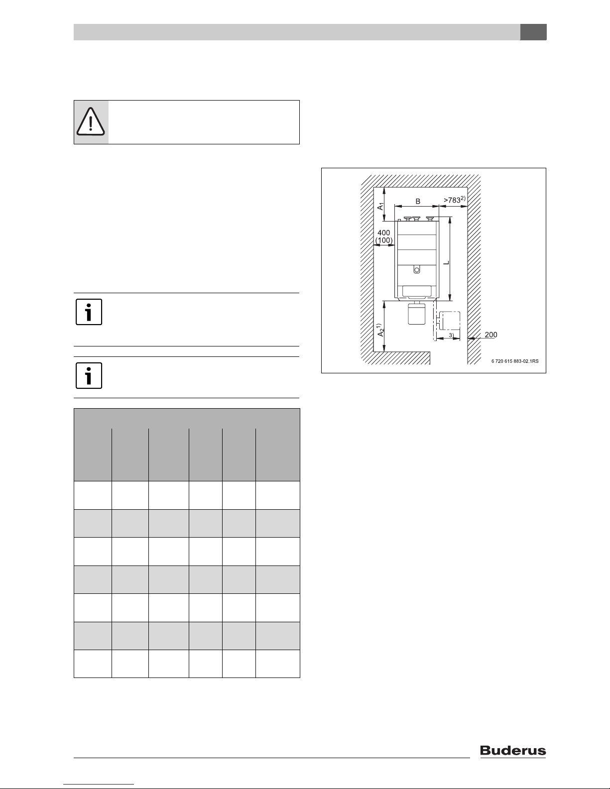
3.5 Boiler positioning
This chapter explains how to properly position the boiler.
3.5.1 Foundation and recommended wall
clearances
B When providing foundations or a support area, observe
the specified minimum wall clearances (values in
brackets) (Æ Fig. 2 and Tab. 4) so that the installation
and maintenance instructions can be followed without
difficulty. The front edge of the boiler should be flush
with the edge of the plinth.
It is useful if there is a drain outlet near the installation
location.
Fig. 2 Boiler room (for dimensions see Tab. 4),
dimensions in mm
1)
In addition to the burner length
3)
take dimension A2 into
consideration when installing a third party burner.
2)
When using a side-mounted control unit holder.
3)
Take account of burner dimensions.
CAUTION: System damage due to frost!
B Install the heating system in a room
protected from the risk of frost.
The support area must be flat and able to
support the applied weight, with a slight
incline to the rear to ensure ventilation of the
boiler.
Make sure there is additional space for noise
silencing.
Recommended (and minimum) wall clearances mm
Boiler
size kW
Clear-
ance
Clear-
ance
Length Width
Width/
Height
A
1
A
2
1)
1) For boiler installations with third party burners, dimension A2
also depends on the burner length
3)
.
L B Transport
145 760
(460)
1700
(1200)
1816 900 720/1340
185 760
(460)
1700
(1200)
1816 900 720/1340
240 800
(500)
1700
(1200)
1845 970 790/1370
310 800
(500)
1700
(1200)
1845 970 790/1370
400 900
(1600)
1750
(1250)
1845 970 790/1570
510 1000
(700)
2000
(1500)
1980 1100 920/1730
640 1000
(700)
2000
(1500)
1980 1100 920/1730
Tab. 3 Wall clearances
Page 12
3
Regulations, standards and guidelines
Logano plus SB615 Gas - We reserve the right to make any changes due to technical modifications.
12
Allow extra space if a flue silencer is to be
installed.
If you wish to fix the control unit to the side of the boiler
using the holder (accessory), you have to ensure
additional clearance (Æ Fig. 2, page 11).
3.5.2 Levelling the boiler
B Level the boiler towards the back using a spirit level to
prevent air pockets forming inside the boiler.
Fig. 3 Level the boiler backwards
(for legend, see Fig. 1, page 6)
3.6 Disposal
Use metal shims to level the boiler.
Please note the following:
B Dispose of packaging in an
environmentally responsible manner.
B Dispose of all heating system components
that have to be replaced at an authorised
disposal site.
Page 13
4
Transporting the boiler
Logano plus SB615 Gas - We reserve the right to make any changes due to technical modifications.
13
4 Transporting the boiler
This chapter describes how to handle the boiler safely
without risk of damage.
B When raising and transporting the boiler, make sure
that the weight is distributed evenly across the forks of
the forklift truck/pallet truck.
4.1 Means of transport
4.1.1 Transporting the boiler using a forklift truck
B Insert the forks of the forklift truck under the front and
the back of the boiler.
4.1.2 Transporting the boiler using two pallet
trucks
B Slide a pallet truck under the front and the back of the
boiler.
B Raise the boiler evenly using the two pallet trucks.
DANGER: Risk to life from incorrectly
secured boiler!
B Use suitable equipment when
transporting the boiler, e.g. two pallet
trucks or a forklift truck.
B When transporting, secure the boiler to
the method of transport to prevent it
slipping.
CAUTION: System damage due to
damaged boiler body!
B The boiler may only be transported with a
forklift truck if the forks are long enough to
extend from the front of the boiler to the
back.
B Prior to lifting the boiler body, check
whether the boiler front and back panels
are positioned on the fork of the forklift
truck.
Page 14

5
Installation of the boiler
Logano plus SB615 Gas - We reserve the right to make any changes due to technical modifications.
14
5 Installation of the boiler
This chapter explains how to correctly install the boiler.
5.1 Checking delivery for completeness
B Upon delivery, check all packaging for damage.
B Check the delivered package(s) for completeness
(Æ Chapter 2.4).
5.2 Disposing of packaging
B Dispose of packaging in an environmentally
responsible manner.
5.3 Minimum clearances / product
dimensions
5.4 Changing the hinging of the burner
door
The burner door can be moved from the right-hand side
(factory-set) to the left-hand side.
B Push the hinge bolts out of the hinges from underneath
[1].
B Refit the washer [2] and the two hinge pins to the
adjacent hinges. Make sure that the washer is
re-installed.
Fig. 4 Reversing the door hinges
1 Hinge pin
2 Washer
CAUTION: System damage due to open
combustion chamber!
The combustion chamber must remain
sealed by the burner door so that the
stainless steel combustion chamber is not
damaged by any welding or grinding work.
B Ensure when fitting the front thermal
insulation pad that the combustion
chamber remains sealed by the burner
door.
Observe the recommended minimum wall
clearances when positioning (Æ Tab. 3,
page 11).
DANGER: Risk of injury from unsupported
door!
B Change the door hinging only when the
door is closed and bolted.
Page 15
5
Installation of the boiler
Logano plus SB615 Gas - We reserve the right to make any changes due to technical modifications.
15
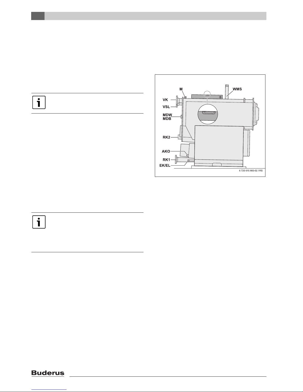
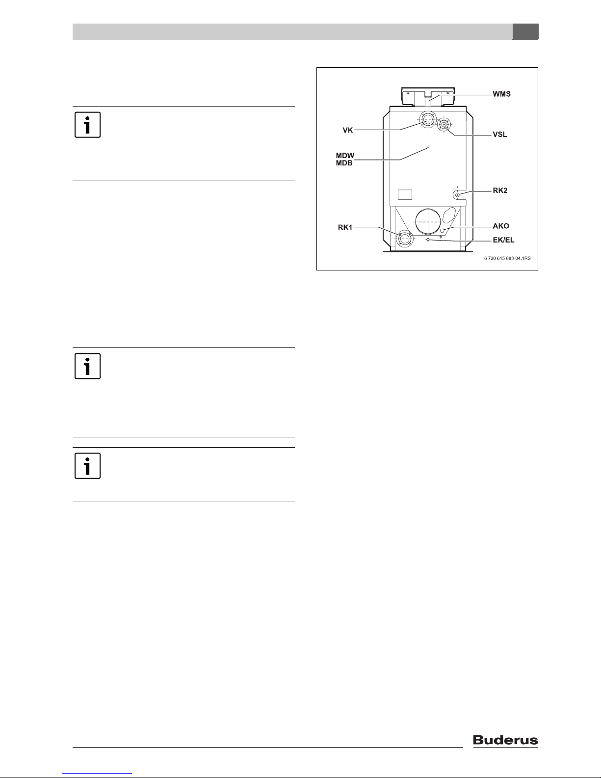
5.5 Installing the minimum pressure
switch and minimum pressure
limiter
B Connect the minimum pressure monitor or minimum
pressure limiter (with R½ to R¼ connection piece
adapter) to the MDW/MDB connection on the boiler
(Æ Fig 5).
Fig. 5 Logano plus SB615 Gas boiler connections
5.6 Low water indicator (accesory),
fitting (400 – 600 kW)
B Seal the flow pipe for the low water indicator into the
2" LWI connection on the boiler (Æ Fig. 5).
B Fit the low water indicator onto the low water indicator
tube.
B If the LWI connection is not being used for the
installation of a low water indicator, remove the plastic
plug and close off the LWI connection with a blanking
plug.
Note that a minimum pressure monitor must
be connected for 145 kW to 240 kW!
For 310 kW (145 kW and higher in Poland)
a minimum pressure limiter (MDB) must be
installed. This requires an R½ to connection
piece adapter R¼ .
For Germany
B For boilers > 300 kW, install a low water
indicator or minimum pressure limiter as
required by DIN-EN 12 828.
B For installation and operation, refer to the
technical documents provided by the
manufacturer.
For Poland
B For boilers > 100 kW, equip the boiler
with a low water indicator as required by
PN-91/B-2414 (p2.5).
Page 16

5
Installation of the boiler
Logano plus SB615 Gas - We reserve the right to make any changes due to technical modifications.
16
5.7 Connecting the boiler to the
pipework
Please observe the following information regarding the
boiler connection to the pipework. This is important for
fault-free operation.
5.7.1 Connecting the return to the boiler
B Connect the heating system return to the boiler return
connections RK1 and RK2 (Æ Fig. 6).
5.7.2 Connecting the flow to the boiler
B Connect the heating system flow to the boiler flow
connection VK (Æ Fig. 6)
5.7.3 Connecting the safety line flow
B Fasten the relief valve to the VSL safety line flow
connection using 4 screws (Æ Fig. 6).
Fig. 6 Logano plus SB615 Gas boiler connections
To protect the boiler from debris within the
system water, we strongly recommend the
installation of a dirt trap in the return leg of the
plant.
CAUTION: System damage due to leaking
connections!
B Ensure pipework connections to and from
the boiler are free of stress.
Install a dirt trap in the return close to the
boiler in order to protect the appliance from
debris within the system water.
CAUTION: System damage from
connecting the wrong components to the
pressure relief!
B Never connect a DHW cylinder or other
heating circuit to the VSL safety line flow
connection (Æ Fig. 6).
Page 17

5
Installation of the boiler
Logano plus SB615 Gas - We reserve the right to make any changes due to technical modifications.
17
5.8 Filling the heating system and
checking connections for leaks
Check the heating system for leaks before commissioning
to ensure there are no leaks when the system is in
operation.
B Fill the heating system with water
(Æ Chapter 6.2).
B Carrying out the leak test.
The testing pressure is based on the normal operating
pressure of the heating system and should be 1.3 times
that pressure, and in any case no less than 1 bar.
B Check all connections for leaks.
DANGER: Risk to health from drinking water
contamination!
B Always observe the regulations and
standards applicable in your country for
the prevention of contamination of
drinking water (e.g. by water from heating
systems).
B Observe EN 1717.
CAUTION: Risk of system damage from
excess pressure when testing for leaks!
Pressure, control and safety equipment may
be damaged through excessive pressure.
B Ensure that, whilst you are carrying out a
leak test, no pressure, control or safety
equipment is fitted, which cannot be shut
off towards the boiler water chamber.
CAUTION: System damage due to thermal
stresses!
B Only fill the system when cold (the flow
temperature must be no more than 40 °C).
B When the heating system is in operation,
do not fill it via the boiler fill and drain valve.
Instead, only use the filling valve in the
heating system (return).
B Pay attention to the water quality as
specified in the operator's log, and record
the volume and quality of the water used
to fill the system.
Page 18

5
Installation of the boiler
Logano plus SB615 Gas - We reserve the right to make any changes due to technical modifications.
18
5.9 Fitting the lagging
B Push the insulation underneath the boiler through to
the opposite side (Æ Fig. 7).
Fig. 7 Push the insulation underneath the boiler
through to the opposite side.
1 Hinge pin
B Wrap thermal insulation jackets overlapping around the
boiler and fix at the top with 5 spring clips [3].
B Close off the cut-out for the low water indicator [1] with
two spring hooks [3].
B Undo the door bolts and open the burner door.
B Place the lower front insulation section on the front of
the boiler body and secure to the right and the left onto
the wrap-around insulation with 2 spring hooks on each
side [3].
B Locate the insulation strip [2] at the top around the
boiler shell ring, and secure to the right and the left
onto the lower front insulation section with two spring
hooks on each side [3].
B Place the upper front insulation section on the front of
the boiler body.
Fig. 8 Fitting and fastening the lagging
1 Low water indicator
2 Strip of lagging material
3 Tension springs
B Close the door again and secure with door bolts.
DANGER: Risk of injury due to burner door
falling off when opened!
B Make sure that both hinge bolts
(Æ Fig. 7, [1]) are inserted.
When fitting the insulation, ensure that the
fabric backing is arranged on the outside and
the cut-outs at the rear.
Keep the cut-outs for the hinges and the
threaded sleeves for the burner door bolts
free.
Page 19

5
Installation of the boiler
Logano plus SB615 Gas - We reserve the right to make any changes due to technical modifications.
19
B Place the rear insulation section onto the rear of the
boiler in the position dictated by the openings and
secure to the right and the left onto the wrap-around
insulation with 4 spring hooks (Æ Fig. 9).
Fig. 9 Positioning and securing the rear insulation
section
1 Tension springs
5.10 Fitting the connection plates
B Insert front connection plate (with trapeze-shaped
cut-out facing downwards) over the threaded studs,
with the 2 holes at the top, and fasten with nuts
(Æ Fig. 10).
B Insert back connection plate (with trapeze-shaped
cut-out facing downwards) over the threaded studs,
with the 2 holes at the top, and fasten with nuts
(Æ Fig. 10).
B Balance the front and rear connection plates with a
spirit level.
Fig. 10 Locating and securing the front and rear
connection plates
The angled sections on the connection
plates should point outwards, and both the
front and rear connection plate should be
horizontally level (Æ Fig. 10).
Page 20

5
Installation of the boiler
Logano plus SB615 Gas - We reserve the right to make any changes due to technical modifications.
20
B Hook side connection plate with the "U" into the
cut-out on each of the front and back connection
plates. Each connecting plate is secured in the front
hole and the rear slot using 2 self-tapping screws.
Fig. 11 Inserting and securing the lateral connection
plates
5.11 Fitting the side panels
B Insert side panels with the flange behind the boiler
frame at the bottom and in the slot in the centre.
Fig. 12 Inserting side panels
The cutout in the flange of each side panel
section must be in the centre of the boiler.
6720615883-30.1RS
Page 21

5
Installation of the boiler
Logano plus SB615 Gas - We reserve the right to make any changes due to technical modifications.
21
B Lift side panels and hook into the folded edge in the
side connection plates [1].
B Press ends of the lagging behind the folded edge on
the side panel.
5.12 Routing the burner cable
B Insert the strain relief [2] for the burner cable [3] with
both pins into the holes on the angled section of the left
or right side panel.
B Adjust the burner cable [3] to the desired length, feed
through the strain relief [2], close tab and fasten to the
base rail with 2 self-tapping screws.
Fig. 13 Hook in the side panels and connect the burner
cable
Page 22

5
Installation of the boiler
Logano plus SB615 Gas - We reserve the right to make any changes due to technical modifications.
22
5.13 Fitting the back plate
For boiler sizes 145 kW to 310 kW, the rear wall is in two
parts (Æ Fig. 14), for boiler sizes 400 kW to 640 kW only
one part (Æ Fig. 15).
Boiler sizes 145 kW to 310 kW
B Secure the lower boiler cover [1] with 5 self-tapping
screws [2] to the side panels.
B Insert the upper rear panel section [4] with the Z-fold
behind the lower rear panel section, and secure onto
the side panels with four self-tapping screws [3].
B Make sure that the two upper self-tapping screws also
pass through the connection plates.
B Secure one or two cable clips [5] or a cable duct on the
fold on the upper rear panel section.
Fig. 14 Screwing the 2-part real panel in place (boiler
rating 145 to 310 kW).
1 Lower rear panel
2 5 self-tapping screws
3 4 self-tapping screws
4 Upper rear panel
5 Cable clamp/cable channel
Boiler sizes 400 kW to 640 kW
B Secure the boiler cover [1]with 4 self-tapping screws
on the right and left-hand side to the side panels.
B Make sure that the two upper self-tapping screws also
pass through the connection plates.
B Secure one or two cable clips [2] or a cable duct on the
fold on the rear panel section.
Fig. 15 Screwing rear panel in place (boiler rating 400
to 600 kW)
1 Back panel
2 Cable clamp/cable channel
Page 23

5
Installation of the boiler
Logano plus SB615 Gas - We reserve the right to make any changes due to technical modifications.
23
5.14 Fitting the front boiler cover
B Place front boiler cover on top of the folded edges of
the side panels and pull forwards until the right and
left-hand hooks click into place in the slot (Æ Fig. 16).
B Screw front boiler cover firmly into the side connection
plates by screwing 2 self-tapping screws through the
tabs on the boiler cover and the folded edge on the
side panels (Æ Fig. 16).
Fig. 16 Fitting the front boiler cover
5.15 Fit and connect the control unit
(accessory)
You can use the following control units with the boiler:
Logamatic 4211, 4212 as well as 4321 and 4322
(accessories).
The control unit can be fitted either on top of the boiler or,
with the side-mounted control unit holder (accessory),
onto the boiler side.
Refer to the enclosed installation instructions if using the
optional control unit side holder.
Fig. 17 shows the control unit and the front cover [1] from
the back.
B Undo both screws from cover [1]. Lift off the cover.
B Fit the control unit at the front by inserting the hooks [4]
into the oval holes in the front boiler cover [5].
B Pull the control unit forwards and then tip back. The
flexible hooks [2] must latch into the rectangular
openings at the rear of the front boiler cover [3].
B Screw the base of the control unit on the left and right
of the cable entry onto the front boiler hood [6] via the
holes [7] using two self-tapping screws.
Fig. 17 Fitting the control unit
1 Cover
2 Resilient hooks
3 Rectangular openings in the front boiler cover
4 Locking tabs
5 Oval holes in front boiler cover
6 Cable entry in the front boiler cover
7 Holes for self-tapping screws
Page 24

5
Installation of the boiler
Logano plus SB615 Gas - We reserve the right to make any changes due to technical modifications.
24
B If necessary, make knock-outs [1] in the rear panel of
the cable duct or remove the rear panel section [2].
Fig. 18 Preparing the cable entry
1 Knock-outs
2 Rear panel component
B Make the plug-in connection in the control unit in
accordance with the labelling on the terminal strip.
B Route the burner cable through the cable entry in the
front boiler cover to the control unit.
B Connect the burner cable to the control unit in
accordance with the labelling on the plug-in connector
strip.
B Make all electrical connections to the appropriate
plug-in connectors according to the wiring diagram.
Observe the following when connecting the
control unit:
B Carefully route the cables/leads and
capillary tubes.
B Never kink capillary tubes during
installation.
B Always have electrical work inside the
heating system carried out by a qualified
electrician or electrical contractor.
B Observe all local regulations.
B Create a permanent connection in
accordance with EN 50165.
The positions of the terminal strips in the
various Logamatic control units are not
identical, however the labelling abbreviations
and colour codes remain the same. E.g. The
outdoor temperature sensor connection is
always labelled FA.
Page 25

5
Installation of the boiler
Logano plus SB615 Gas - We reserve the right to make any changes due to technical modifications.
25
Secure all cables with cable clips (included with control
unit). To do this, carry out the following steps:
1. With the cable in place, insert the cable clips, as shown
in Fig. 19, from above into the slits in the clip frame.
2. Slide the cable clamp downwards.
3. Press in.
4. Flip the lever up.
B Put the cover (Æ Fig. 17, page 23) back on the control
unit.
B Tighten screws (Æ Fig. 17, page 23) to secure control
unit cover.
Fig. 19 Securing the cable with cable clips
5.16 Installing the temperature sensor
set
Test point M is located at the top rear of the boiler.
B Route the capillary tubes with temperature sensors and
quarter dummy plugs to the sensor well in test point M
and insert the temperature sensor into the sensor well
until it bottoms out.
Fig. 20 Inserting temperature sensor into the sensor
well
6720615883-31.1RS
.
.
.
.
.
Observe the following points before installing
the temperature sensor set:
B Take care to ensure correct cable and
capillary pipe routing.
B Create a permanent mains power
connection in accordance with EN 50165.
B Observe all local regulations.
Page 26

5
Installation of the boiler
Logano plus SB615 Gas - We reserve the right to make any changes due to technical modifications.
26
B The plastic coil [2] for holding together the temperature
sensor is pushed back automatically when it is
inserted.
B Coil up any excess cable, capillary tube and sensor
leads and place on the boiler body insulation.
B Connect the temperature sensors to the control unit.
Fig. 21 Inserting the plastic coil into the sensor well
1 Compensating spring
2 Plastic spiral
3 Sensor retainer
4 Sensor well
5.17 Fitting the boiler cover sections
Boiler sizes 145 kW to 400 kW
4 boiler cover sections
Boiler sizes 510 kW to 640 kW
5 boiler cover sections
B Loosely locate the boiler cover sections one after the
other on the right and left side panels.
Fig. 22 Fitting the boiler cover sections - Example
1 Recess for boiler sizes 400 kW and upwards
To ensure a good contact between sensor
well [4] and sensor surfaces, and thereby a
reliable temperature transfer, the
compensating spring [1] must be pushed in
between the sensors.
6720615883-32.1RS
1
2
3
4
From 400 kW upwards, the second cover
part is provided with a recess (Æ Fig. 22).
The rear parts are identical and are
positioned with their fold forward.
Page 27

5
Installation of the boiler
Logano plus SB615 Gas - We reserve the right to make any changes due to technical modifications.
27
5.18 Fitting the front panel
B Push the tabs on the lower connection plate from
below into the slots to the left and right on the side
panels and secure the connection plate with two
machine screws on the front of the boiler body.
Fig. 23 Securing the lower connection plate
B Hook the lower front panel section with the four hooks
[1] into the slots to the left and right on the side panels.
B Insert the upper front panel section with its hooks [2]
into the slots on the lower front panel, and hook the top
into the front boiler cover [3].
Fig. 24 Fasten lower and upper front panels
1 Hook lower front panel
2 Hook upper front panel
3 Hooking the upper front panel into the boiler cover
Page 28

5
Installation of the boiler
Logano plus SB615 Gas - We reserve the right to make any changes due to technical modifications.
28
5.19 Securing the shield, device label and
data plate
B Fit the decorative panel [1] by inserting the hooks into
the front panel.
B Fix appliance insignia plate [2] to front panel.
B Attach the data plate [3] to either the left or right side
panel, depending on which is most convenient.
Fig. 25 Attaching the data plate
1 Restrictor
2 Device label
3 Data plate
5.20 Connecting and filling the
neutraliser (accessory)
Please refer to the separate installation manual for
installation and maintenance of the neutralisation device.
B Fit the drain hose [1] with a hose clip to the condensate
outlet (siphon).
Fig. 26 Connecting and filling the neutraliser
1 Drain hose
CAUTION: System damage!
You must ensure that the condensate
generally runs via the flue pipe into the boiler.
If this is not possible, you must only use
stainless steel or plastic tees in the separate
pipe inlet.
B In ceramic flue systems, you must fit a silt
trap (pot).
Page 29

5
Installation of the boiler
Logano plus SB615 Gas - We reserve the right to make any changes due to technical modifications.
29
5.21 Installing condensate pipework
B Fit the siphon provided to the outlet on the flue gas
collector [5].
B Unscrew the locking cap and fill the siphon with about
two litres of water.
Fig. 27 Installing condensate pipework
1 Connection elbow
2 Locking cap
3 Siphon
4 Siphon outlet to neutralisation device or waste water pipe
5 Flue gas collector
When installing the condensate pipework,
observe the following:
B Carefully drain the condensate created
inside the boiler and possibly in the flue
pipe.
B Drain the condensate into the sewerage
system in accordance with the
requirements in your country.
B Observe regional requirements.
DANGER: Risk to life from poisoning!
Siphons which are not filled with water, or
open connections, can cause a risk to life
from escaping flue gas.
B Fill the siphon with water.
B Ensure that the siphon and flue gas
connections are sealed.
B Ensure that the sealing disc with gasket is
seated in the locking cap.
Neutralisation devices are available as
accessories.
B Install neutralisation device (accessory) as
detailed in the installation instructions.
Page 30

5
Installation of the boiler
Logano plus SB615 Gas - We reserve the right to make any changes due to technical modifications.
30
5.22 Connecting the flue side of the
heating system
This chapter explains how to install the boiler to the flue.
5.22.1 General information on flue systems
B The flue gases in question must be led outside into the
open air via flue pipes and flues.
B Use flue pipes and flues that conform to building
regulations and are resistant to humidity.
B Before commissioning the heating system, check that
the flue gas system used is suitable for the boiler.
B Follow guidelines in the planning instruction.
B Check the flue connection for leaks.
B Observe the flue system manufacturer’s installation
instructions.
5.22.2 Fitting the flue pipe sealing collar
(accessory)
B Fit the flue pipe sealing collar as described in the
separate installation manual.
5.22.3 Fitting the flue temperature sensor
(accessory)
B Fit the flue gas temperature sensor as described in the
separate installation manual.
Page 31

5
Installation of the boiler
Logano plus SB615 Gas - We reserve the right to make any changes due to technical modifications.
31
5.23 Fitting burner (accessory) and
connecting gas supply
This chapter explains how to fit a burner.
B A burner that is made dirty by building work must be
cleaned before being commissioned.
5.23.1 Fitting the burner plate
A burner plate without pre-drilled holes is included with
the boiler.
If you have not ordered the predrilled burner plates from
Buderus, the enclosed blanking plate will have to be
machined accordingly onsite.
B Drill or cut the burner plate to match the required blast
tube diameter.
B Drill holes for fastening the boiler using the burner
connecting flange as a template.
B Fasten the burner plate to the burner door using the
hex-head bolts and washers (seal with gasket).
CAUTION: System damage from incorrect
burner!
B Only use burners that meet the technical
requirements of the Logano plus SB615
Gas boiler.
CAUTION: Damage to system through
incorrect burner adjustment (overloading)!
B Make sure that the value set does not
exceed the combustion heat output
Qn (Hi) stated on the rating plate.
Do not work on the burner plate when
installed.
Predrilled burner plates are available from
Buderus upon request (accessory).
Page 32

5
Installation of the boiler
Logano plus SB615 Gas - We reserve the right to make any changes due to technical modifications.
32
5.23.2 Fitting the burner to the burner plate
B Depending on the burner make or type, you must use
the corresponding burner plate or make necessary
alterations. Adjust the hole in the burner door thermal
insulation if necessary.
B Seal the gap between blast tube and lagging [1]
on-site.
Fig. 28 Sealing the gap between burner and insulation
(dimensions in mm).
1 Area between blast tube and thermal insulation
When fitting the burner (accessory), you
must observe the burner manufacturer’s
instructions.
Page 33

5
Installation of the boiler
Logano plus SB615 Gas - We reserve the right to make any changes due to technical modifications.
33
5.23.3 Connecting the gas supply
B Make the gas connection in accordance with all locally
applicable regulations.
B Connect the gas pipe without stress to the gas
connector.
B Install a gas shut-off valve in the gas supply pipe.
B Before initial start-up, check for external leakage on the
new length of piping up to the gas valve.
B If a leak is discovered, all connections must be
checked using a frothing agent.
We recommend that a gas filter be installed
in the pipework in accordance with local
regulations.
DANGER: Risk to life from gas explosion!
Leaks may have been created on pipes and
fittings following the commissioning work.
B Carry out the correct leak tests.
B Only use approved leak detection agents
for leak detection.
CAUTION: Risk of system damage due to
short circuit!
B Cover areas at risk prior to carrying out a
leak test.
B Do not spray the leak solution on wiring
openings, plugs or electrical connections.
Do not allow it to drip onto them either.
Page 34

6
Initial operation
Logano plus SB615 Gas - We reserve the right to make any changes due to technical modifications.
34
6 Initial operation
This chapter describes how to start up the heating
system.
B Perform start up according to the user manuals for the
boiler, burner, low water indicator and electronic
heating circuit control.
B When handing over the system, show the operator how
it functions and how to operate it, and hand over the
technical documentation to them. Complete the
commissioning report.
B Draw the operator's attention to the maintenance
requirements and recommend arranging a
maintenance contract.
6.1 Flushing the heating system
Flush the heating system prior to commissioning to
prevent contamination that could e.g. block and damage
the circulation pump.
CAUTION: System damage due to heavy
dust deposits!
B Do not operate the boiler where heavy
dust contamination persists, e.g. through
building work inside the boiler room.
DANGER: Risk to health from drinking water
contamination!
B Always observe the regulations and
standards applicable in your country for
the prevention of contamination of
drinking water (e.g. by water from heating
systems).
B Observe EN 1717.
CAUTION: Boiler damage from corrosion
and sludge!
B It is essential to flush the entire heating
system before filling with heating water.
B Check the quality of the fill and top-up
water, so as to avoid scaling and
corrosion. (Note the “Water treatment...”
operator's log.)
If a heating system contains several heating
circuits, these must be flushed one after the
other.
Page 35

6
Initial operation
Logano plus SB615 Gas - We reserve the right to make any changes due to technical modifications.
35
B Isolate the heating flow and return on the boiler.
B Connect the heating flow to a fresh water connection.
B Connect the hose to the heating system return.
B Put the hose from the heating return into a drain.
B Open all shut-off devices and radiator valves in the
heating system.
B Flush the heating system with fresh water until clear
water emerges from the heating return.
6.2 Filling the heating system
For the correct use and treatment of the fill and top-up
water, follow the Code of Practice K8 in the applicable
Buderus catalogue, as well as VDI 2035.
The pH value of the heating water will increase after the
heating system has been filled.
B After 3 – 6 months (during the first service), check
whether the pH value of the heating water has
stabilised.
DANGER: Risk to life from escaping flue
gases!
B Before commissioning the boiler or the
neutralisation device, pour about 10 litres
of water into the inspection opening or
into the heating space in order to fill up the
neutralisation holder and prevent the
escape of flue gases from the boiler
siphon.
DANGER: Risk to health from drinking water
contamination!
B Always observe the regulations and
standards applicable in your country for
the prevention of contamination of
drinking water (e.g. by water from heating
systems).
B Observe EN 1717.
CAUTION: System damage due to thermal
stresses!
B Only fill the system when cold (the flow
temperature must be no more than 40 °C).
B When the heating system is in operation,
do not fill it via the boiler fill and drain valve.
Instead, only use the filling valve in the
heating system (return).
B Pay attention to the water quality as
specified in the operator's log, and record
the volume and quality of the water used
to fill the system.
Page 36

6
Initial operation
Logano plus SB615 Gas - We reserve the right to make any changes due to technical modifications.
36
6.3 Preparing the heating system for
operation
Observe the following when commissioning:
B Before commissioning, bleed the heating system via
the venting facility provided for this purpose.
B Check that the inspection opening of the flue gas
collector is closed (Æ Fig. 32, page 42).
B Ensure that the burner door is secured with door bolts.
B Check that the safety equipment is functioning
properly.
6.4 Commissioning the control unit and
the burner
B Use the control unit to start the boiler.
By commissioning the control unit, you also automatically
commission the burner. The burner can then be started via
the control unit. For further details, see the installation
instructions of the relevant control unit or burner.
B Complete the commissioning report in the technical
burner documentation.
Page 37

6
Initial operation
Logano plus SB615 Gas - We reserve the right to make any changes due to technical modifications.
37
6.5 Commissioning report
B Sign all commissioning work as completed and enter
the date.
Commissioning tasks Page (individual steps) Comments
(signature)
1. Fill the heating system with water. page 35
2. Vent the heating system. page 36
3. Carry out leak testing (gas, flue gas, water). page 33, page 30, page 17
4. Start up the control unit. Æ control unit documentation
5. Start-up the burner. Æ burner documentation
6. Perform a leak test on the hot gas side. After being in
operation for a short time, retighten the burner door bolts
to prevent leaks around the door as a result of the packing cord settling.
7. Inform the system user, hand over the technical docu-
mentation, and enter the fuel used in this heating system
in the table of the operating instructions.
8. Confirm correct commissioning.
Company stamp/signature/date
Page 38

7
Shutdown
Logano plus SB615 Gas - We reserve the right to make any changes due to technical modifications.
38
7Shutdown
7.1 Shutting down the heating system
Shut down your heating system using the control unit. The
burner is automatically shut down when the control unit is
shut down.
B Turn the switch on the control unit to the “0” (OFF)
position.
B Isolate the fuel supply to the burner.
7.2 Shutting down the heating system in
an emergency
B In other dangerous circumstances, immediately isolate
the main shut-off valve and the electrical power supply
of the heating system via the boiler room main circuit
breaker or the emergency isolation switch for the boiler
room.
B Isolate the fuel supply to the burner.
CAUTION: System damage due to frost!
When the heating system is switched off, the
system water can freeze up and expand in
cold weather.
B Protect your heating system against frost
when temperatures below zero are
expected. Where there are no frost stats
to protect the vulnerable parts of the
system, drain the heating water from the
lowest point of the heating system using
the fill & drain valve or the radiator. The air
vent valve at the highest point in the
system must also be open.
CAUTION: System damage due to frost!
The heating system can freeze up during a
power failure or if the power supply has been
switched off.
B Check the “Control unit settings” to
ensure the system remains operational
(especially when there is a risk of frost).
In an emergency (and only in an emergency),
switch OFF the heating system via the boiler
room circuit breaker or heating system
emergency isolation switch.
Page 39

8
Inspection/maintenance
Logano plus SB615 Gas - We reserve the right to make any changes due to technical modifications.
39
8 Inspection/maintenance
8.1 General notes
Offer your customer an annual contract covering
inspection and demand-dependent service. Refer to the
“Inspection and maintenance reports” Chapter 8.6 for
information about what such contracts should contain.
8.2 Preparing the boiler for inspection
and maintenance
B Shut down the heating system (Æ Chapter 7).
B Check the general condition of the heating system.
B Visually and functionally check the heating system.
B Check all system parts that carry fuel or water for leaks
and visible corrosion.
The operator is obliged under the terms of
paragraph 9 of the heating plant legislation to
arrange to have the heating system cleaned
and maintained.
B The entire condensing unit (including any
neutralisation device) must undergo
maintenance once a year.
B We recommend arranging an inspection
and maintenance contract.
B For burner maintenance, follow the burner
manufacturer’s maintenance instructions.
DANGER: Risk to life from electricution
when the heating system is open!
B Before opening the heating system,
disconnect the heating system from the
power supply by means of the emergency
isolation switch or the relevant circuit
breaker in the main fuse board.
B Prevent unintentional reconnection of the
electricty supply.
DANGER: Risk to life from gas explosion!
B Any work on components may only be
carried out by an approved contractor.
EN 303 permits an amount of leakage from
the hot gas side of the boiler.
Page 40

8
Inspection/maintenance
Logano plus SB615 Gas - We reserve the right to make any changes due to technical modifications.
40
8.3 Cleaning the boiler
B Remove upper and lower front panels.
B Remove the front thermal insulation.
B Undo the door bolts and open the burner door.
Fig. 29 Removing the front panel and thermal insulation
B Loosen nuts from the clamping angle, swivel the
clamping angle away and remove the return bonnet.
B Clean the combustion chamber and the heating
surfaces.
Fig. 30 Removing the return hood and opening the
burner door
DANGER: Risk of injury due to burner door
falling off when opened!
B Make sure that both hinge bolts
(Æ Fig. 7, [1], page 18) are inserted.
CAUTION: Boiler damage due to not using
the appropriate cleaning equipment!
B Only Buderus cleaning equipment may be
used for cleaning.
For wet-cleaning, we recommend
high-pressure cleaning equipment.
B Do not pour cleaning residues through the
neutralisation device.
B Do not block up the condensate drain
(Æ Fig. 32, page 42) when cleaning.
Page 41

8
Inspection/maintenance
Logano plus SB615 Gas - We reserve the right to make any changes due to technical modifications.
41
B Feed brushes through the secondary heating pipes.
B Use a vacuum cleaner if necessary to remove any
cleaning residues.
Fig. 31 Feed brushes through the secondary heating
pipes
If you do not push all the bristle part of
cleaning brush right through the secondary
heating pipe, you will find it very difficult to
remove the brush from the pipe.
B Push the bristle part of the cleaning brush
right through the secondary heating pipe
until the bristles emerge at the other end of
the pipe.
CAUTION: System damage due to faulty
seals!
B Check the seals around the burner door
and return bonnet, replacing if necessary.
Page 42

8
Inspection/maintenance
Logano plus SB615 Gas - We reserve the right to make any changes due to technical modifications.
42
If spray cleaning, follow the operating instructions
for the relevant cleaning equipment!
Spray must not enter the control unit!
B Bolt burner door shut.
B Put the return bonnet in place and seal it tight with the
clamping angle (Æ Fig. 30, page 40). Pay attention to
fitted position.
B Fasten front lagging with tension springs.
B Fit lower and upper front panels of the boiler
(Æ Fig. 29, page 40).
B Put system back into operation.
8.4 Cleaning the flue gas collector
To be able to remove combustion residues from the flue
gas collector, the clean-out cover has to be removed. This
is located on the rear panel.
B Undo the wing nuts on the cleaning cover [1] and
remove the cleaning cover.
B Remove all loose combustion residues from the flue
gas collector.
B Refit the clean-out cover in the reverse order of
removal.
B Check whether the siphon is filled with water.
Fig. 32 Inspection aperture flue gas collector
1 Cleaning access covers
DANGER: Risk to life from poisoning!
Siphons which are not filled with water, or
open connections, can cause a risk to life
from escaping flue gas.
B Fill the siphon with water.
B Ensure that the siphon and flue gas
connections are sealed.
B Ensure that the sealing disc with gasket is
seated in the locking cap.
Page 43

8
Inspection/maintenance
Logano plus SB615 Gas - We reserve the right to make any changes due to technical modifications.
43
8.5 Checking the heating system water
pressure
A distinction is generally made between open vented and
sealed unvented heating systems. In practice, open
heating systems are seldom installed. We will therefore
be using sealed systems to demonstrate how you can
check the water pressure.
Open heating systems
For open heating systems, the hydrometer needle [1]
should be within the red band [3].
Fig. 33 Hydrometer for open unvented heating systems
1 Hydrometer needle
2 Green needle
3 Red field
Sealed heating systems
In sealed systems, the pressure gauge needle [2] must lie
within the green field [3]. The red pressure gauge needle
[1] must be set to the required heating system pressure.
B Set the manometer pointer accordingly.
B Check the heating system water pressure.
Fig. 34 Pressure gauge for sealed unvented heating
systems
1 Red needle
2 Pressure gauge needle
3 Green band
6720615883-33.1RS
1
2
3
Generate the operating pressure required for
the heating system.
CAUTION: System damage due to frequent
topping up!
The heating system may be damaged,
depending on water quality, by corrosion or
scaling if you frequently need to top-up your
system with water.
B Ensure that the heating system is vented
correctly.
B Check the heating system for leaks and
proper operation of the expansion vessel.
B Observe the requirements in respect of
water quality.
6 720 615 876-59.1RS
3
2
1
Page 44

8
Inspection/maintenance
Logano plus SB615 Gas - We reserve the right to make any changes due to technical modifications.
44
8.6 Inspection and maintenance reports
The inspection and maintenance reports provide an
overview of the required inspection and maintenance
work.
B Initial and date the completed inspection work.
Inspection work Page (individual steps) Comments
1. Check the general condition of the heating system.
2. Visual and function check of the heating system.
3. Check the components in contact with fuel and water
throughout the system for the following:
• Tightness/leaks
• visible signs of corrosion
• Signs of ageing
4. Check the combustion chamber and the heating surface
for contamination; shut down the system for this step.
page 39
5. Check the burner. Æ burner documentation
6. Check the flue for function and safety. Æ burner documentation
7. Check the water pressure of the heating system and
pre-charge pressure of the diaphragm expansion vessel.
page 43
8. If necessary, check the function of the DHW cylinder and
the magnesium anode.
Æ DHW cylinder documentation
9. Check the control unit settings. Æ control unit documenta-
tion
10. Final inspection check; take measurements and document figures and test results.
Confirm professional inspection with signature, date and company stamp
Page 45

8
Inspection/maintenance
Logano plus SB615 Gas - We reserve the right to make any changes due to technical modifications.
45
Condition-based maintenance Page (individual steps) Comments
1. Shut down the heating system. (Disconnect your heating
system from the main electrical supply, isolate main fuel
shut-off, disconnect flue pipe from burner.)
page 38
2. Cleaning hot gas flues (heating surfaces). page 40
3. Clean the combustion chamber.
Clean the condensate outlet.
Cleaning the flue collector.
page 40
4. Check and, if required, replace gaskets/packing cord on
the burner door.
5. Start up the heating system. page 34
6. Final maintenance check; take measurements and document figures and test results.
Æ burner documentation
7. Check the function and operational safety (safety equipment).
Confirm professional maintenance with signature, date and company stamp
Page 46

8
Logano plus SB615 Gas - We reserve the right to make any changes due to technical modifications.
46
Notes
Page 47

8
Logano plus SB615 Gas - We reserve the right to make any changes due to technical modifications.
47
Notes
Page 48

Bosch Thermotechnik GmbH
Sophienstrasse 30-32
D-35576 Wetzlar
www.buderus.com
C & F Quadrant Ltd.
Unit L40 Cherry Orchard Industrial Estate
Cherry Orchard, Dublin 10
Tel.: 01.6305700
Fax.: 01.6305706 / 01.6305715
www.cfquadrant.ie
E-mail: sales@cfquadrant.ie
Buderus
Cotswold Way, Warndon, Worcester WR4 9SW
Customer service: 0870 421 5933
Technical support: 0870 421 5944
Fax: 01905 753130
www.buderus-commercial.co.uk
In the UK and IE, Buderus is a brand name of
Bosch Thermotechnology Ltd.
 Loading...