

Page 1
6 720 801 773-00.2ITL
DANGER:
These installation instructions are intended solely
for use by a licensed heating contractor or service
technician. Read all instructions before installing.
Perform steps exactly in the order given. Failure to
follow these instructions can result in severe injury,
death or property damage.
DANGER:
Cette notice d’installation doit être utilisée uniquement par des installateurs chauffagistes ou des
techniciens de maintenance qualifiés. Lisez attentivement toutes les consignes avant l’installation.
Exécutez les actions précisément dans l’ordre indiqué. En cas de non-respect, vous risquez de subir
de sérieuses blessures pouvant conduire à la mort
ou d’entraîner de lourds dommages matériels.
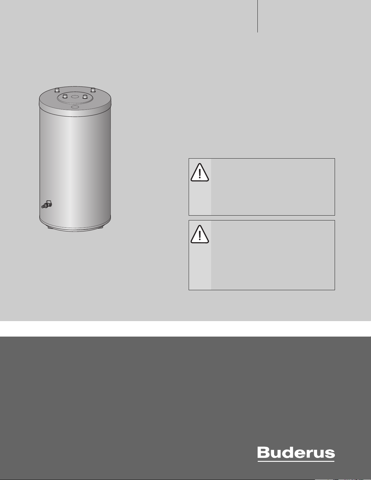
Installation and maintenance instructions
Notice d’installation et d’entretien
S 32/5
[en] Installation and maintenance instructions for the contractor . . . . . . . . . . . . 2
[fr] Notice d'installation et d'entretien pour le professionnel . . . . . . . . . . . . . . . 18
Read carefully prior to installation and maintenance.
6 720 804 007 (2013/02) US/CA
À lire attentivement avant le montage et la maintenance.
Page 2
Table of Contents
Table of Contents
1 Safety Considerations and Symbol Descriptions . . . . . . . . . . 3
1.1 Explanation of symbols . . . . . . . . . . . . . . . . . . . . . . . . . . 3
1.2 Safety considerations . . . . . . . . . . . . . . . . . . . . . . . . . . . 3
1.3 Instructions for the owner and operator . . . . . . . . . . . . . 4
2 Product information . . . . . . . . . . . . . . . . . . . . . . . . . . . . . . . . . . . 5
2.1 Included items . . . . . . . . . . . . . . . . . . . . . . . . . . . . . . . . . 5
2.2 Intended use . . . . . . . . . . . . . . . . . . . . . . . . . . . . . . . . . . . 5
2.3 Poduct description . . . . . . . . . . . . . . . . . . . . . . . . . . . . . . 6
2.4 Rating plate . . . . . . . . . . . . . . . . . . . . . . . . . . . . . . . . . . . . 6
2.5 Pressure drop curve of heating coil . . . . . . . . . . . . . . . . . 6
2.6 Specifications . . . . . . . . . . . . . . . . . . . . . . . . . . . . . . . . . . 7
2.7 Physical and connection dimensions . . . . . . . . . . . . . . . 8
3 Standards, regulations and directives . . . . . . . . . . . . . . . . . . . 9
4 Moving the tank . . . . . . . . . . . . . . . . . . . . . . . . . . . . . . . . . . . . . . 9
5 Installation . . . . . . . . . . . . . . . . . . . . . . . . . . . . . . . . . . . . . . . . . . . 9
5.1 Boiler installation . . . . . . . . . . . . . . . . . . . . . . . . . . . . . . . 9
5.1.1 Requirements for installation location . . . . . . . . . . . . . . 9
5.1.2 Positioning the tank . . . . . . . . . . . . . . . . . . . . . . . . . . . . 10
5.2 Water connections . . . . . . . . . . . . . . . . . . . . . . . . . . . . . 11
5.2.1 Connecting the tank on the water side . . . . . . . . . . . . . 11
5.2.2 Installing a T&P safety valve (on-site) . . . . . . . . . . . . . . 11
5.3 Install a tank water temperature sensor (accessory)
or aquastat (accessory) . . . . . . . . . . . . . . . . . . . . . . . . 11
6 Commissioning . . . . . . . . . . . . . . . . . . . . . . . . . . . . . . . . . . . . . . 13
6.1 Commissioning the tank . . . . . . . . . . . . . . . . . . . . . . . . 13
7 Shutdown . . . . . . . . . . . . . . . . . . . . . . . . . . . . . . . . . . . . . . . . . . . 13
7.1 Shutting down the tank . . . . . . . . . . . . . . . . . . . . . . . . . 13
7.2 Shutting down the heating system when there is
a risk of frost . . . . . . . . . . . . . . . . . . . . . . . . . . . . . . . . . 13
8 Environmental Protection / Disposal . . . . . . . . . . . . . . . . . . . 14
9 Maintenance . . . . . . . . . . . . . . . . . . . . . . . . . . . . . . . . . . . . . . . . 14
9.1 Testing relief valve . . . . . . . . . . . . . . . . . . . . . . . . . . . . . 14
9.1.1 Drain the tank . . . . . . . . . . . . . . . . . . . . . . . . . . . . . . . . . 14
9.1.2 Descaling/cleaning the tank . . . . . . . . . . . . . . . . . . . . . . 14
9.1.3 Checking the magnesium anode . . . . . . . . . . . . . . . . . . 15
9.2 Re-commissioning after performing maintenance . . . . 15
10 Spare Parts . . . . . . . . . . . . . . . . . . . . . . . . . . . . . . . . . . . . . . . . . 16
S 32/5 – 6 720 804 007 (2013/02)2
Page 3
1 Safety Considerations and Symbol
Descriptions
1.1 Explanation of symbols
Warnings
Warnings are indicated by a warning triangle.
In addition, signal words at the beginning of a warning
are used to indicate the type and seriousness of the
ensuing risk if measures for minimizing damage are not
taken.
The following keywords are defined and can be used in this document:
• NOTICE indicates that damage to property may occur.
• CAUTION indicates that personal injury may occur.
• WARNING indicates that severe personal injury may occur.
• DANGER indicates that severe personal injury or death may occur.
Important Information
Safety Considerations and Symbol Descriptions
1
1.2 Safety considerations
Read all instructions before installing. Perform the steps in the indicated
sequence. Have the tank inspected by a trained service technician at
least once every year. Failure to comply with these instructions can
result in severe, possibly fatal, personal injury as well as damage to
property and equipment.
Installation and servicing
▶ Risk of fire from soldering and brazing!
Take appropriate protective measures when soldering and brazing as
the insulation is flammable, for example, cover the insulation.
▶ Ensure that only a licensed contractor installs or services the tank.
▶ Use installation material with adequate temperature stability.
Installation and commissioning
▶ In the Commonwealth of Massachusetts, the tank must be installed by
a licensed plumber.
▶ The electrical power must be connected by a licensed electrician.
The wiring diagram must be followed.
▶ Do not install this device in rooms with a high moisture level
(e.g. bathrooms, saunas).
Important information that presents no risk to people or
property is indicated with this symbol. It is separated by
horizontal lines above and below the text.
Additional symbols
Symbol Function
▶ Sequence of steps
Cross-reference to another part of this document
• Listing/list entry
– Listing/list entry (2nd level)
Tab. 1
Function
▶ To ensure that the tank functions properly, heed these installation and
maintenance instructions.
▶ Never close the blow-off line of the T&P safety valve. For safety
reasons, water may escape during heating.
Danger from electric shock
▶ Ensure that only an authorized contractor performs electrical work.
▶ Before performing electrical work, disconnect the power and secure
the unit against unintentional reconnection.
▶ Ensure the system has been disconnected from the power supply.
Risk of scalding at the hot water draw-off point
▶ When the tank is in operation, temperatures in excess of 122 °F
(50 °C) can occur. To limit the temperature at the tap, install a
thermostatic DHW mixing valve.
▶ Water heated for washing the laundry, dishes and for other cleaning
purposes can cause scalding and permanent injuries.
▶ Children, elderly, and handicapped persons are more likely to be
permanently injured by hot water. Never leave such individuals in the
tub or shower unattended under any circumstances. Children must
not be allowed to operate hot water faucets themselves or to fill a
bathtub.
▶ If the building has occupants in the above groups who operate hot
water faucets, or state laws / local ordinances stipulate specific water
temperatures, take the following precautions:
– Use the lowest possible temperature setting.
– To prevent scalding, install a tempering device, such as an
automatic mixing valve, at hot water tap or water heater. Select and
install the automatic mixing valve in accordance with the valve
manufacturer's recommendations and instructions.
▶ Water exiting from drain valves can be extremely hot. To avoid
injuries:
– Check that all connections are tight.
– Direct exiting water away from people.
▶ Measures must be taken to protect against excessive temperature and
pressure! Installation of a T&P safety valve is required.
S 32/5 – 6 720 804 007 (2013/02) 3
Page 4
1
Safety Considerations and Symbol Descriptions
The chart below shows the relationship between water temperature and
time until there is a risk of scalding. It can be used as the basis for
determining the safest water temperature for your application.
Temperature Time to severe scalding
120 °F (48 °C) longer than 5 minutes
125 °F (51 °C) 1.5 to 2 minutes
130 °F (54 °C) approx. 30 seconds
135 °F (57 °C) approx. 10 seconds
140 °F (60 °C) less than 5 seconds
145 °F (62 °C) less than 3 seconds
150 °F (65 °C) approx. 1.5 seconds
155 °F (68 °C) approx. 1 second
Tab. 2 Approximate time-temperature relationship until there is a risk
of scalding
1) Source: M oritz, A.R. and Henriques, F.C., Jr. (1947). Studies of thermal injury. II.
The relative importance of time and surface temperature in the causation of
cutaneous burns, Am J of Pathol, 23, 695-720.
1)
To protect against corrosion and ensure compliance with the rules for
electrical safety, observe the following points:
▶ Use metal fittings for drinking water heating systems with plastic
piping.
▶ Use only original accessories from the manufacturer.
▶ When installation of the tank is complete, inspect the ground
conductor (including metal fittings).
Maintenance
Customers are advised to:
▶ Sign a maintenance and inspection contract with an authorized
contractor. Inspect and maintain the tank as necessary on a yearly
basis. Service as needed.
▶ Use only original spare parts.
1.3 Instructions for the owner and operator
WARNING: Risk of scalding at the taps!
There is a risk of scalding at the taps if the tank
temperature is set above 122 °F (50 °C) and during
thermal disinfection.
▶ Advise users that they should only draw off mixed
water. Otherwise, install a thermostatic DHW mixing
valve.
NOTICE: Risk of tank damage from excessively high
pressure.
▶ Never plug the discharge line of the T&P safety valve.
▶ Explain the operation and handling of the heating system and tank,
making a particular point of safety-relevant features.
▶ Explain the function and how to check the T&P safety valve.
▶ Hand all enclosed documents over to the owner/operator.
▶ Recommendation for the user: Sign a maintenance and inspection
contract with a licensed contractor.
▶ Highlight the following for the user:
– Water may be discharged from the T&P safety valve during heat-up.
– T he blow-off line on the T&P safety valve must always be kept open.
– Check that the T&P safety valve operates properly at least once
yearly.
– The tank must be inspected annually and maintained as required.
Flooding
▶ After a flood, do not use the appliance if any part has been
submerged. Damage to appliances that have been submerged can be
quite severe and pose numerous safety risks.
▶ An appliance that was subject to flooding must be replaced.
S 32/5 – 6 720 804 007 (2013/02)4
Page 5
2 Product information
6 720 801 773-13.1ITL
1
2
3
4
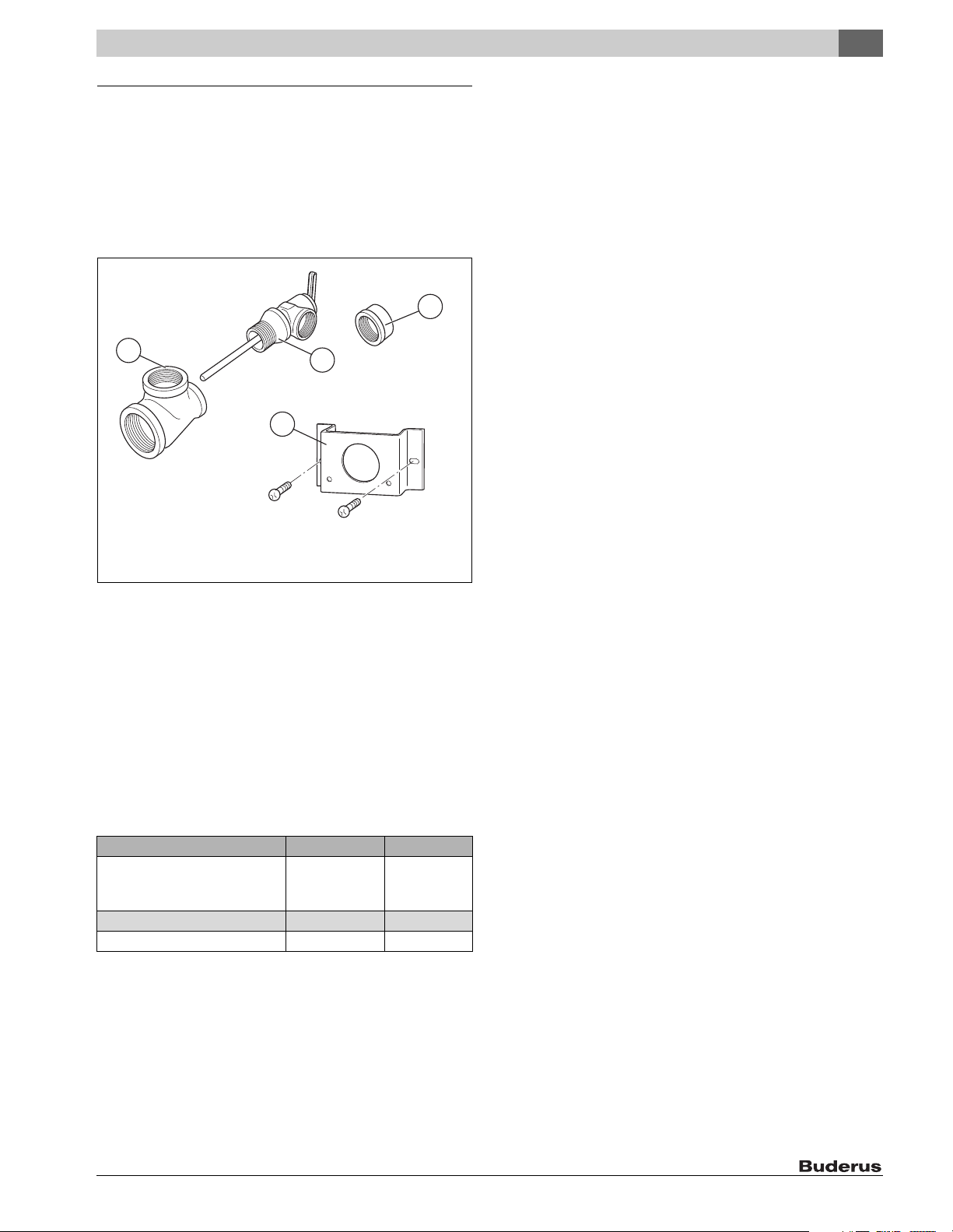
2.1 Included items
•Tank
• Tank drain (factory installed)
• Installation and Service Instructions
• Compensating spring for aquastat or tank temperature sensor
•B-KIT
Product information
2
Fig. 1 B-kit
[1] Tee section 1" x 1" x ¾ "
[2] Temperature and pressure relief valve
[3] Coupling ¾ "(3x)
[4] Bracket for aquastat, screws for aquastat bracket (2x)
2.2 Intended use
The tank is designed for heating and storing drinking water. Please
observe national, regional, and local codes, regulations, guidelines and
standards for drinking water.
Install this tank only in sealed unvented hydronic heating systems.
Any other purpose is considered improper use. Any resulting damage is
excluded from the manufacturer's warranty.
Requirements for drinking water Unit
Water hardness, min. ppm
grain/US gallon
°dH
pH value, min. – max. 6.5 – 9.5
Conductivity, min. – max. μS/cm 130 – 1500
Tab. 3 Requirements for drinking water
36
2.1
2
S 32/5 – 6 720 804 007 (2013/02) 5
Page 6
2
6 720 801 773-14.1ITL
111098
4
5
2
3
76
1
12
6 720 801 773-02.4ITL
flow rate [gpm]
Pressure drop [ft of head]
0
0.5
1
2
3
4
1.5
2.5
3.5
2 4 6 8 10 12
A
Product information
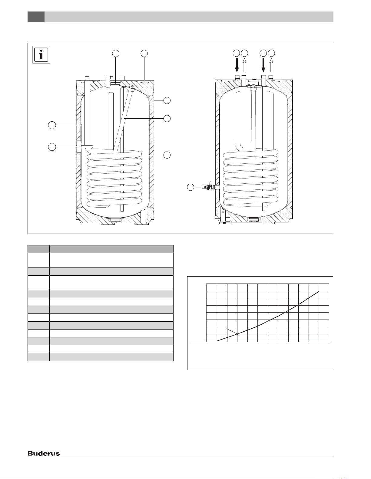
2.3 Poduct description
Fig. 2 Poduct description
Item Description
1 Jacket, painted sheet metal with rigid polyurethane foam
insulation, 2" (50 mm)
2 Magnesium anode
3 Heat exchanger for heating by boiler, smooth enameled
tubing
4 Sensor well for aquastat or boiler temperature sensor
5 Tank, enameled steel
6 Inspection port for service and cleaning, on the top
7 PS top cover
8 Boiler flow
9 DHW outlet
10 Cold water inlet
11 Boiler return
12 Drain valve
Tab. 4 Description du produit
2.4 Rating plate
The data plate is located at the top rear of the tank.
2.5 Pressure drop curve of heating coil
Fig. 3 Pressure drop curve of heating coil
Example:
[A] 4 gpm
0.5 feet of head
S 32/5 – 6 720 804 007 (2013/02)6
Page 7
2.6 Specifications
Unit S 32/5
Tank capacity
Tank capacity (total) gal
(l)
Max. flow rate gpm
(l/min)
Max. DHW temperature °F
(°C)
Max. operating pressure DHW psi
(bar)
Tank performance
Domestic cold water inlet temperature °F
(°C)
Domestic hot water outlet temperature °F
(°C)
DHW temperature rise °F
(°C)
Coil supply water temperature (boiler water) °F
(°C)
Coil flow rate (boiler water) gpm
(l/h)
Coil pressure drop (boiler water) f o h
(mbar)
Continuous rating gph
(l/h)
gpm
(l/min)2(8)
First hour rating gph
(l/h)
Max. heat input to tank btu/hr
(kW)
Heat exchanger
Contents gal
(l)
Surface area ft
Standby heat loss (149 °F (65 °C) DHW temperature, 68 °F (20 °C) room temperature) °F/h
Max. coil supply water temperature °F
Max. coil operating pressure psi
Tab. 5 Specifications
2
(m2)
(K/h)
(°C)
(bar)
31.7
(120)
3.2
(12)
203
(95)
145
(10)
50
(10)
140
(60)
90
(50)
176
(80)
11.45
(2600)
3.38
(101)
120
(456)
143
(540)
90422
(26,5)
1.8
(6,8)
10-3/4
(1,0)
0.59
(0,33)
230
(110)
232
(16)
Product information
2
S 32/5 – 6 720 804 007 (2013/02) 7
Page 8
2
Product information
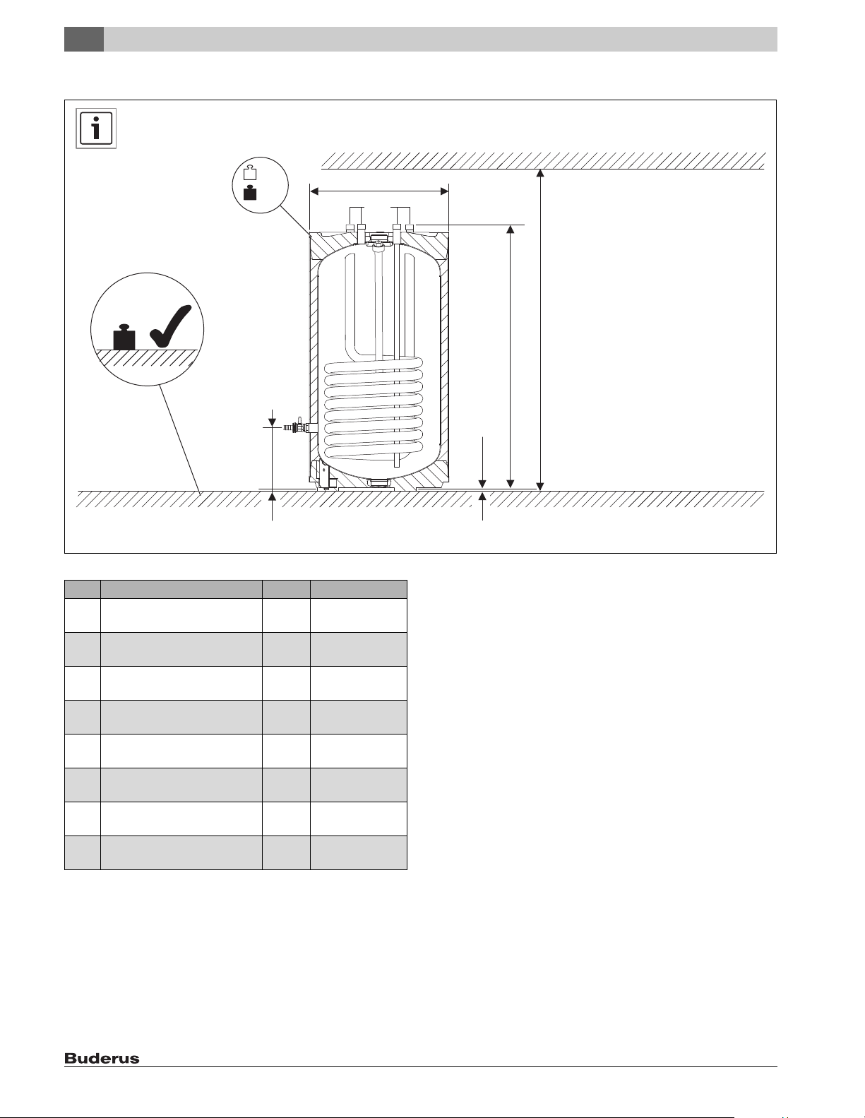
2.7 Physical and connection dimensions
B
C
A
Fig. 4 Physical and connection dimensions
E
D
3/4
II
H
G
F
6 720 801 773-12.2T
Item Description Unit S 32/5
A Minimum floor weight carrying
capacity
B Weight (empty) Ib
C Weight (full) Ib
D Diameter inch
E Height of drain valve inch
F Clearance off floor inch
G Height of connections inch
H Minimum room height for anode
replacement
Tab. 6 Physical and connection dimensions
Ib
(kg)
(kg)
(kg)
(mm)
(mm)
(mm)
(mm)
inch
(mm)
424
(192)
160
(72)
424
(192)
21-3/4
(550)
8-1/2
(218)
1/2
(12.5)
38-5/8
(980)
57-1/2
(1460)
S 32/5 – 6 720 804 007 (2013/02)8
Page 9
Standards, regulations and directives
6 720 800 035-03.1ITL
3
3 Standards, regulations and directives
Observe all national, state, and local code, regulations
and standards applicable to installation and operation of
the tank!
All electrical components must be approved for the USA
and Canada.
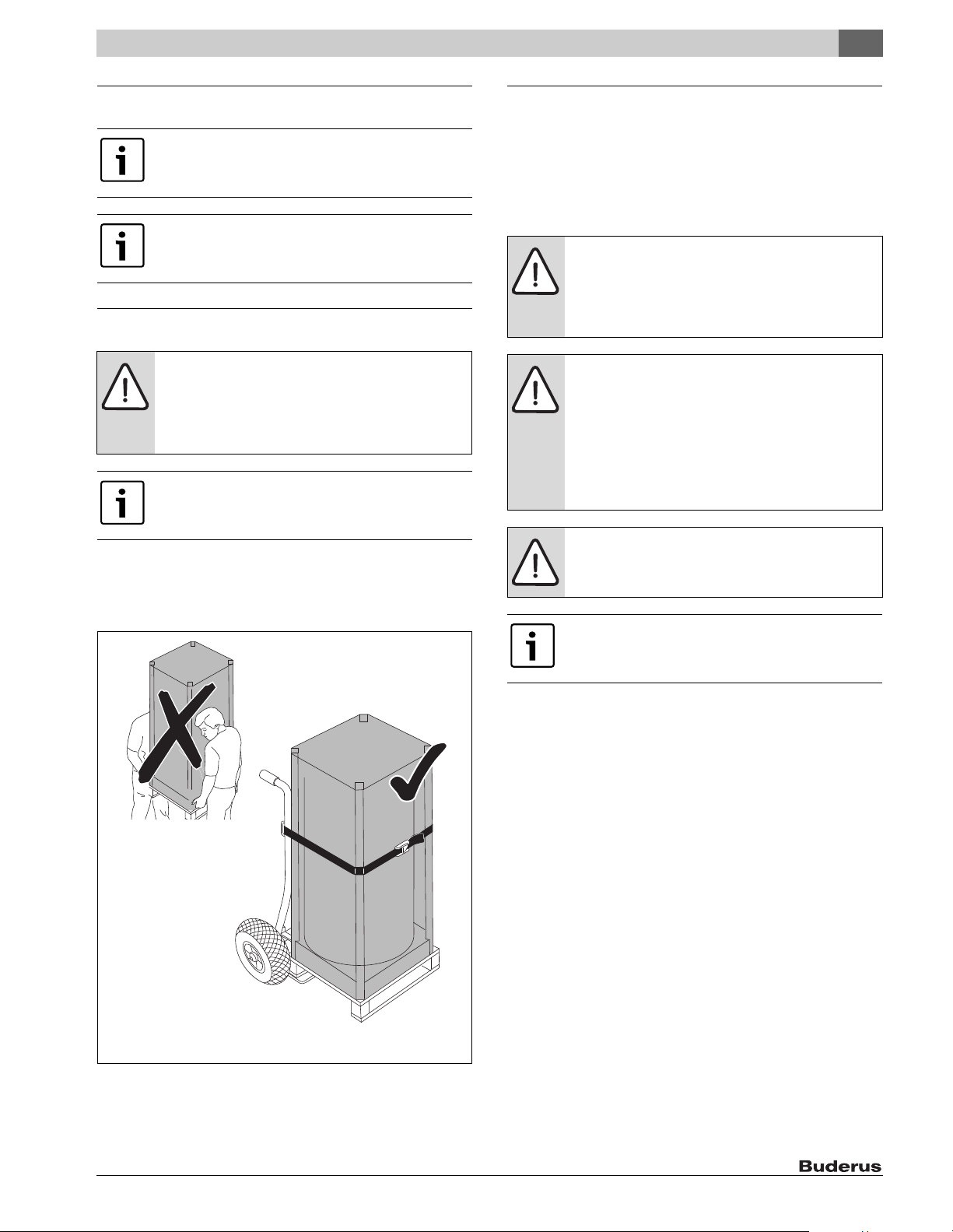
4 Moving the tank
WARNING: Risk of injury from carrying heavy loads and
inadequately securing loads for transport!
▶ Use suitable means of transportation, e.g. a dolly with
strap.
▶ Secure the load against falling.
Where possible, do not remove the tank from its
packaging until it has reached the installation location.
This ensures protection during handling.
▶ Position the dolly at the back of the packed tank.
▶ Secure the tank to the means of transportation with a strap.
▶ Transport the tank to the installation location.
▶ Only remove the tank from the packaging at the installation location.
5 Installation
The tank is delivered fully assembled.
▶ Check that the tank is complete and undamaged.
5.1 Boiler installation
5.1.1 Requirements for installation location
NOTICE: Risk of damage from inadequate load-bearing
capacity of the supporting substructure or unsuitable
floor surface!
▶ Ensure that the installation area is level and offers
sufficient load-bearing capacity.
NOTICE: Risk of damage from stress cracking and
corrosion!
▶ Position the tank in a dry room free from the risk of
freezing.
▶ Install the tank only in closed-loop, unvented hydronic
heating systems.
▶ Open expansion vessels may NOT be used with this
tank.
NOTICE: Install an adequate drain pan if required by
code, or if a leak could result in property damage. Follow
drain pan manufacturer's instructions.
At least 19" (480 mm) clearance needed above the tank
for magnesium anode removal.
Fig. 5 Transporting with a dolly
▶ Place the tank on a raised platform if there is a risk that water may
collect at the installation site.
▶ The installation site must be a dry and frost-free room.
▶ Observe the minimum room height ( Tab. 6, page 8) in the
installation room. No minimum wall clearance required.
▶ Maintain a distance of 2" (51 mm) from heated pipes and combustible
surfaces.
S 32/5 – 6 720 804 007 (2013/02) 9
Page 10
5
6 720 800 035-04.1ITL
6 720 801 769-15.1ITL
1.
2.
3.
6 720 801 769-13.1ITL
Installation
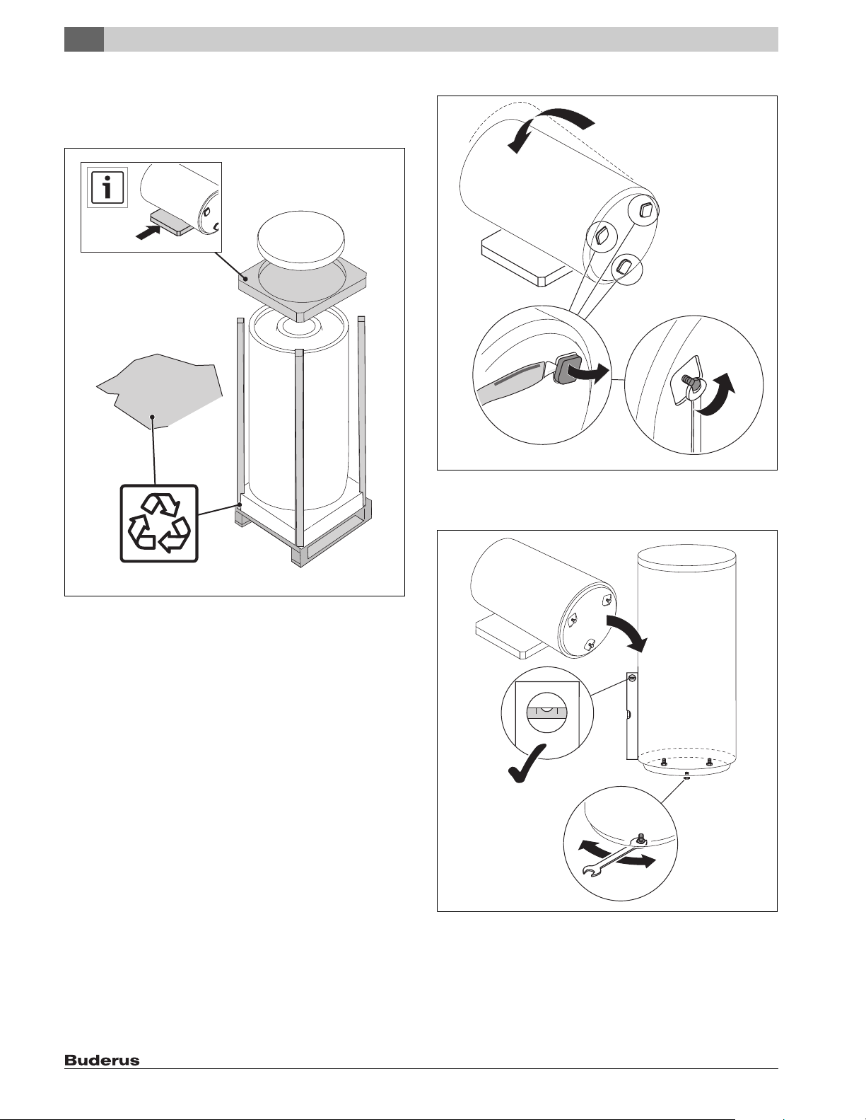
5.1.2 Positioning the tank
▶ Unpack the tank by removing the wrap, wooden boards and foam pad
on the top.
▶ Lay the foam pad on the floor to serve as a mat.
▶ Unscrew the screw-in feet [3].
Fig. 7 Laying the tank on its side and exposing the adjustable feet
▶ Position the tank on a level floor that has adequate load-bearing
capacity ( Fig. 8).
Fig. 6 Unpacking the tank
▶ Carefully lay the tank on the foam pad ( Fig. 7, [1]).
▶ Cut out the projections in the foam bottom ( Fig. 7, [2]).
Fig. 8 Positioning the tank
▶ With the aid of the adjustable feet, align the tank vertically ( Fig. 8).
▶ Remove the protective caps from the connections.
▶ Use Teflon tape or Teflon cord to seal the connections. Do not use
hemp to seal the connections.
S 32/5 – 6 720 804 007 (2013/02)10
Page 11

Installation
5
5.2 Water connections
DANGER: Risk of fire from soldering and brazing!
▶ Take appropriate safety measures when soldering
and brazing as the thermal insulation is flammable.
For example, cover up the thermal insulation.
▶ Check tank jacket for damage after completing work.
DANGER: Risk of injury from contaminated water!
Work carried out without due care for cleanliness
contaminates the drinking water.
▶ Install in accordance with national standards and
guidelines.
NOTICE: Risk of corrosion from damage to the enamel
finish!
▶ Tighten connections to the tank only "hand-tight".
5.2.1 Connecting the tank on the water side
System example with all recommended valves and shut-offs ( Fig. 9).
2
5.2.2 Installing a T&P safety valve (on-site)
▶ Install a listed T&P safety valve that is approved for drinking water
(≥ ¾ ")in the DHW outlet.
▶ This tank must be installed with a new T&P safety valve.
▶ The T&P valve must be sized no smaller than the rated tank capacity.
▶ Observe the safety valve installation instructions.
▶ T&P discharge pipe:
– The discharge pipe must be at least equal to the outlet cross-
section of the safety valve.
– Route the discharge line from the T&P valve directly to an adequate
drain (maximum length 6 ft (2m) with no more than two 90°elbows).
– The discharge line must terminate at an adequate drain in order to
prevent property damage from spillage.
– Check that the T&P safety valve operates properly at least once
annually.
▶ Never plug the blow-off line. During heating, water may be discharged
for operational reasons at any time.
5.3 Install a tank water temperature sensor (accessory)
or aquastat (accessory)
DANGER: Risk of fatal injury from electric shock!
▶ Isolate the system electrically prior to commencing
work on the system.
3
123
Fig. 9 Installation example
[1] Tank coil supply
[2] DHW outlet
[3] Cold water inlet
[4] Boiler return
▶ Use installation material that is heat-resistant to 230 °F (110 °C).
▶ Never use open, vented expansion vessels.
▶ Use metal connection fittings in water heating systems with plastic
lines.
▶ If using a check valve in the cold water supply: Install a safety valve
between the non-return valve and the cold water inlet.
▶ Install a pre ssure reducer if the static supply water system pressure is
in excess of 72.5 psi (5 bar).
4
6 720 801 773-10.1ITL
Connect the electrical power and set the temperature on
the DHW temperature sensor or the aquastat as shown in
the respective aquastat or control manufacturer's
instructions.
Install a tank temperature sensor or an aquastat on the tank to measure
and monitor the hot water temperature.
S 32/5 – 6 720 804 007 (2013/02) 11
Page 12

5
6 720 648 100-09.1ITL
2
1
3
5
4
Installation
Installing the DHW temperature sensor
▶ Take the tank temperature sensor [3] from the scope of delivery of
the control panel (accessories).
▶ Insert the temperature sensor and compensation spring [2] in the
sensor well [1] and push fully home.
The compensating spring [2] ensures contact between the sensor well
and sensor surfaces, and a reliable temperature reading.
Always ensure that the full length of the sensor surface is
in contact with the sensor well.
1
2
3
Installing aquastat
▶ Remove cover from the aquastat. To do so, undo the screwon the top.
▶ If necessary, remove any unnecessary attachments. Attach bracket
[3] to Aquastat [2] by means of 2 self-tapping screws [1].
2
3
1
6 720 648 100-08.1ITL
Fig. 11 Attaching the aquastat to the bracket
[1] Self-tapping screws C-ST 4.2x13 mm
[2] Aquastat
[3] Bracket
▶ Feed the temperature sensor [4] with the compensating spring [5]
into the sensor well [3].
▶ Attach Aquastat [2] to tank by means of 2 self-tapping sheet metal
screws [1].
▶ Replace the cover of the aquastat [2].
6 720 801 773-08.1ITL
Fig. 10 Installing the DHW temperature sensor
[1] Sensor Well
[2] Compensating spring
[3] Temperature sensor
▶ Route the sensor lead to the boiler or control panel and ensure the
cable is not strained. This cable must not be in contact with any hot
boiler parts.
▶ In the case a sensor is being used without a compensating spring, the
empty space in the sensor well must be filled with a sufficient amount
of heat-conducting paste.
Fig. 12 Installing aquastat
[1] Self-tapping screws C-ST 4.2x13 mm
[2] Aquastat
[3] Sensor Well
[4] Temperature sensor
[5] Compensating spring
S 32/5 – 6 720 804 007 (2013/02)12
Page 13

Commissioning
6
4
1
2
3
Fig. 13 Connecting the tank components
[1] Tee section with P&T safety valve
[2] Bracket with aquastat
[3] Drain valve
[4] Coupling
6 720 801 773-03.4ITL
6 Commissioning
NOTICE: Risk of system damage from excessive
pressure!
Excessive pressure can result in tension cracks in the
enamel coating.
▶ Never plug the discharge line of the T&P safety valve.
6.1 Commissioning the tank
Have the installer of the heating system or a qualified contractor
commission the equipment.
▶ Commission the boiler and additional accessories in accordance with
manufacturer's instructions or the appropriate installation and
operating instructions.
Use only drinking water to check the tank for leaks. On
the DHW side, the test pressure must not exceed 145 psi
(10 bar) gauge pressure.
▶ To bleed air from the tank, open the highest tap/valve.
▶ To fill the tank, open the shut-off valve for the cold water inlet.
▶ Flush the tank and piping thoroughly prior to commissioning.
▶ Before heating up, verify that the boiler, tank and pipework are filled
with water.
▶ Check all connections, piping and the inspection port for leaks.
7 Shutdown
7.1 Shutting down the tank
▶ Switch off the temperature controller at the control panel, shut of the
heating system emergency shutoff switch, or disengage the heating
system circuit breaker.
WARNING: Risk of scalding from hot water!
▶ Let the tank cool down sufficiently.
▶ Close the cold water inlet shutoff valve.
▶ Drain the tank via the drain valve by opening the highest faucet.
▶ Close the shut-off valves to and from the boiler.
▶ Depressurize the heat exchanger.
▶ Drain and blow out the heat exchanger.
▶ To prevent corrosion, dry out the inner space and keep the insp ection
port covers open.
7.2 Shutting down the heating system when there is a risk
of frost
▶ Shut down the heating system and the tank as shown in chapter 7.1.
Fully drain the tank – even the lowest section of the tank
and the heating coil.
S 32/5 – 6 720 804 007 (2013/02) 13
Page 14

8
Environmental Protection / Disposal
8 Environmental Protection / Disposal
Environmental protection is a fundamental principle of the
Bosch Group.
Quality of products, efficiency and environmental protection are equally
important objectives for us. All legislation pertaining to the environment
is strictly observed.
Packaging
For the packaging, we participate in the country-specific recycling
systems, which guarantees optimal recycling. All packaging materials
used are environmentally-friendly and recyclable.
Old appliances
Old appliances contain materials that should be recycled.
The relevant assemblies are easy to separate, and all plastics are
identified. This allows the various components to be sorted for
appropriate recycling or disposal.
9.1.2 Descaling/cleaning the tank
▶ Close the cold water inlet shutoff valve.
▶ Drain the tank via the drain valve by opening the highest faucet.
▶ Check the tank interior for contamination (lime scale deposits,
sediment).
In order to improve the cleaning effect, heat up the
indirect coil prior to hosing them down with a water jet.
The thermal shock effect helps to loosen encrustations
(e. g. lime deposits).
NOTICE: Damage to the enamel finish!
▶ Do not use tools for the removal of deposits from the
interior of the tank as it may damage the enamel liner.
▶ Hose down the inside of the tank.
9 Maintenance
▶ Allow the tank to cool down sufficiently before performing any
maintenance.
▶ Carry out cleaning and maintenance procedures in the specified
intervals.
▶ Remedy all faults immediately.
▶ Use original spare parts only!
▶ The tank must be inspected annually and maintained as required.
9.1 Testing relief valve
▶ Check the T&P safety valve annually.
9.1.1 Drain the tank
▶ Isolate the tank on the DHW side from the piping by closing the shut-
off valves.
▶ Open a high-level tap to vent the system.
▶ Open drain valve ( Fig. 2 [12], page 6).
72 Psi (5 bar)
50 °F (10 °C)
6 720 801 773-04.1ITL
Fig. 14 Hosing down the inside of the tank
▶ Use a wet & dry vacuum cleaner with plastic suction hose to remove
the residues.
▶ Seal the plug back into the inspection port.
S 32/5 – 6 720 804 007 (2013/02)14
Page 15

Maintenance
6 720 801 708-12.1ITL
1.
2.
9
9.1.3 Checking the magnesium anode
If the magnesium anode is not serviced properly, the
warranty is void.
Annual service records must be kept in a safe location
and submitted together with the original purchase
receipt in the event of a warranty claim.
The purpose of the anode rod is to protect the tank against corrosion. It
is critical that the anode rod be inspection once a year to determine
whether it requires replacing.
Upon inspection, the anode rod surface should appear sm ooth. If the rod
surface appears pitted, bumpy, rusty, scale has built up on the surface,
or if the rod is less than 5/8" (15 mm) in diameter, then it must be
replaced.
Certain installations may require more frequent replacement of the
anode rod:
• Recirculation applications,
• Poor water quality,
• Galvanic/electrolytic corrosion,
• High flow applications.
In the event of poor water quality it is recommended that a water
treatment professional be consulted for water treatment options.
Damage resulting from failure to replace the anode rod is not covered
under tank warranty.
9.2 Re-commissioning after performing maintenance
▶ Re-commission the tank by following the procedure in chapter 6.1.
Never bring the magnesium anode surface in contact
with oil or grease.
▶ Keep everything clean.
▶ Shut off the cold water inlet and DHW outlet.
▶ Depressurize the tank.
▶ Remove and inspect the magnesium anode.
Fig. 15
S 32/5 – 6 720 804 007 (2013/02) 15
Page 16

10
Spare Parts
10 Spare Parts
10
2
6
2
3
1
7
17
13
13
14
Fig. 16 Spare parts for S 32/5
9
5
6 720 801 773-06.3ITL
S 32/5 – 6 720 804 007 (2013/02)16
Page 17

Spare Parts
Item Article description Product No. Number
1 Cover lid set D550 8 718 543 403 0 1
2 Cap, white 8 718 543 369 0 1
3 Plug G1 ½ with PTFE ring 63004276 1
5 Screw ISO4017 M10x30 A3K 7 747 022 050 10
6 Temperature sensor well 1- ¼ " (31.5 mm) Hostalen 7 747 020 191 1
7 Temperature sensor well 32-1/3" (820 mm) Hostalen 7 747 020 190 1
9 Drain valve ½ " 63005974 1
10 Anode G1" D26x505 mm 8 718 571 347 0 1
13 Sheet metal screw St 4.2x13 7 747 027 696 10
14 Retaining plate for the aquastat 63032088 1
17 Spring clip 8 718 224 081 0 1
Logo Buderus 8 718 541 573 0
Tab. 7
10
S 32/5 – 6 720 804 007 (2013/02) 17
Page 18

Sommaire
Sommaire
1 Consignes de sécurité et explication des symboles . . . . . . . 19
1.1 Explication des symboles . . . . . . . . . . . . . . . . . . . . . . . . 19
1.2 Consignes de sécurité . . . . . . . . . . . . . . . . . . . . . . . . . . 19
1.3 Initiation de l’utilisateur . . . . . . . . . . . . . . . . . . . . . . . . . 20
2 Informations produit . . . . . . . . . . . . . . . . . . . . . . . . . . . . . . . . . 21
2.1 Pièces fournies . . . . . . . . . . . . . . . . . . . . . . . . . . . . . . . . 21
2.2 Utilisation conforme . . . . . . . . . . . . . . . . . . . . . . . . . . . . 21
2.3 Description du produit . . . . . . . . . . . . . . . . . . . . . . . . . . 22
2.4 Plaque signalétique . . . . . . . . . . . . . . . . . . . . . . . . . . . . 22
2.5 Courbe des pertes de pression échangeur thermique . 22
2.6 Données techniques . . . . . . . . . . . . . . . . . . . . . . . . . . . . 23
2.7 Dimensions de construction et de raccordement . . . . 24
3 Normes, prescriptions et directives . . . . . . . . . . . . . . . . . . . . 25
4 Transport . . . . . . . . . . . . . . . . . . . . . . . . . . . . . . . . . . . . . . . . . . . 25
5 Montage . . . . . . . . . . . . . . . . . . . . . . . . . . . . . . . . . . . . . . . . . . . . 25
5.1 Installation . . . . . . . . . . . . . . . . . . . . . . . . . . . . . . . . . . . 25
5.1.1 Exigences requises pour le lieu d’installation . . . . . . . . 25
5.1.2 Mise en place du ballon d’eau chaude sanitaire . . . . . . 26
5.2 Raccordements hydrauliques . . . . . . . . . . . . . . . . . . . . 27
5.2.1 Effectuer le raccordement hydraulique du ballon
d’eau chaude sanitaire . . . . . . . . . . . . . . . . . . . . . . . . . . 27
5.2.2 Installer la soupape de sécurité pour la température
et la pression (sur site) . . . . . . . . . . . . . . . . . . . . . . . . . 27
5.3 Monter la sonde de température du ballon solaire
(accessoire) ou l’aquastat (accessoire) . . . . . . . . . . . . 27
10 Pièces de rechange . . . . . . . . . . . . . . . . . . . . . . . . . . . . . . . . . . 32
6 Mise en service . . . . . . . . . . . . . . . . . . . . . . . . . . . . . . . . . . . . . . 29
6.1 Mise en service du ballon d’eau chaude sanitaire . . . . . 29
7 Mise hors service . . . . . . . . . . . . . . . . . . . . . . . . . . . . . . . . . . . . 29
7.1 Mise hors service du ballon d’eau chaude sanitaire . . . 29
7.2 Mise hors service de l’installation de chauffage
en cas de risques de gel . . . . . . . . . . . . . . . . . . . . . . . . 30
8 Protection de l’environnement/Recyclage . . . . . . . . . . . . . . . 30
9 Entretien . . . . . . . . . . . . . . . . . . . . . . . . . . . . . . . . . . . . . . . . . . . 30
9.1 Contrôler la soupape de sécurité . . . . . . . . . . . . . . . . . . 30
9.1.1 Vidanger le préparateur d’ECS . . . . . . . . . . . . . . . . . . . 30
9.1.2 Détartrer/nettoyer le ballon ECS . . . . . . . . . . . . . . . . . . 30
9.1.3 Contrôle de l’anode au magnésium . . . . . . . . . . . . . . . . 31
9.2 Remise en service après l'entretien . . . . . . . . . . . . . . . . 31
S 32/5 – 6 720 804 007 (2013/02)18
Page 19

1 Consignes de sécurité et explication des
symboles
1.1 Explication des symboles
Avertissements
Les avertissements sont indiqués dans le texte par un
triangle de signalisation.
En outre, les mots de signalement caractérisent le type
et l’importance des conséquences éventuelles si les mesures nécessaires pour éviter le danger ne sont pas respectées.
Les mots de signalement suivants sont définis et peuvent être utilisés
dans le présent document :
• AVIS signale le risque de dégâts matériels.
• PRUDENCE signale le risque d'accidents corporels légers à moyens.
• AVERTISSEMENT signale le risque d’accidents corporels graves à
mortels.
• DANGER signale le risque d’accidents graves à mortels.
Informations importantes
Consignes de sécurité et explication des symboles
1
1.2 Consignes de sécurité
Lisez attentivement toutes les consignes avant l’installation. Exécuter
les étapes dans l’ordre indiqué. Faire contrôler le ballon d’eau chaude
sanitaire par un technicien qualifié au moins une fois par an. Le non-respect de ces consignes peut entraîner des accidents graves voire mortels
et/ou des dégâts matériels.
Montage et entretien
▶ Risque d’incendie en raison des travaux de soudure !
L’isolation thermique étant inflammable, prendre des mesures de
sécurité appropriées pour effectuer tous les travaux de brasage et de
soudage, en recouvrant l’isolation thermique par exemple.
▶ S’assurer que les travaux d’installation et de maintenance sont exclu-
sivement réalisés par un professionnel agréé.
▶ Utiliser des matériaux suffisamment résistants aux températures éle-
vées.
Installation et mise en service
▶ Au « Commonwealth of Massachusetts », le ballon d’eau chaude sani-
taire doit être mis en place par un installateur agréé.
▶ Faire réaliser les branchements électriques exclusivement par un
électricien agréé. Respecter le schéma de connexion !
▶ Ne pas monter cet appareil dans des pièces humides (par ex. salle de
bain, sauna).
Les informations importantes ne concernant pas de situations à risques pour l'homme ou le matériel sont signalées par le symbole ci-contre. Elles sont limitées par
des lignes dans la partie inférieure et supérieure du
texte.
Autres symboles
Symbole Signification
▶Étape à suivre
Renvois à un autre passage dans le document
• Énumération / Enregistrement dans la liste
– Énumération / Entrée de la liste (2e niveau)
Tabl. 1
Fonction
▶ Respecter cette notice d’installation et d’entretien afin de garantir un
fonctionnement parfait.
▶ Ne pas obturer la conduite de purge de la soupape de sécurité T&D.
Pendant le chauffage, de l’eau risque de s’écouler pour des raisons de
sécurité.
Risques d’électrocution
▶ S’assurer que les travaux électriques sont réalisés exclusivement par
un électricien autorisé.
▶ Avant de commencer les travaux d’électricité, couper le courant du
câble d’alimentation sur tous les pôles et protéger l’installation contre
tout réenclenchement involontaire.
▶ Vérifier que l’installation est hors tension.
Risques de brûlure aux points de puisage de l’eau chaude sanitaire
▶ Les températures du ballon d’eau chaude sanitaire pendant son fonc-
tionnement peuvent dépasser 122 °F (50 °C). Pour limiter la température de puisage, installer un mélangeur thermostatique.
▶ L’eau chauffée utilisée pour la lessive, la vaisselle et d’autres tâches
de nettoyage peut provoquer des brûlures et des blessures permanentes.
▶ Chez les enfants, les personnes âgées et sénile ou mentalement han-
dicapée, il existe un risque accru de blessure permanente à l’eau
chaude. Ne jamais laisser ces personnes sans surveillance dans la baignoire ou sous la douc he. Ne p as autoriser les jeunes enfants à actionner eux-mêmes les robinets d’eau chaude ou de remplir une baignoire.
▶ Si dans un bâtiment les personnes comprises dans les catégories pré-
cédemment citées actionnent des robinets d’eau chaude ou si les
directives locales imposent des températures précises pour les robinets d’eau chaude, prendre les mesures spécifiques suivantes :
– Utiliser le réglage de température le plus bas possible.
S 32/5 – 6 720 804 007 (2013/02) 19
Page 20

1
Consignes de sécurité et explication des symboles
– Installer une sécurité anti-brûlure, par ex. une vanne mélangeur
automatique, sur le robinet d’eau chaude ou le chauffe-eau. Choisir
et installer la vanne mélangeur automatique en fonction des recommandations et consignes du fabricant de la vanne.
▶ L’eau s’échappant des vannes de vidange peut être extrêmement
chaude. Pour éviter les blessures :
– Assurer l’étanchéité des raccordements.
– Eloigner les écoulements d’eau de toute personne.
▶ Prendre des mesures de protection contre les températures et pres-
sions trop élevées ! Installer impérativement une soupape de sécurité
pour la température et la pression.
Le tableau suivant présente le rapport entre la température de l’eau et le
temps nécessaire à l’apparition de brûlures. Vous pouvez ainsi déterminer les températures d’eau les plus sûres pour votre application.
Température Temps jusqu’à brûlure importante
120 °F (48 °C) plus de 5 minutes
125 °F (51 °C) 1,5 à 2 minutes
130 °F (54 °C) env. 30 secondes
135 °F (57 °C) env. 10 seconde
140 °F (60 °C) moins de 5 secondes
145 °F (62 °C) moins de 3 secondes
150 °F (65 °C) env. 1,5 seconde
155 °F (68 °C) env. 1 seconde
Tabl. 2 Rapport approximatif temps-température lors de l’apparition de
1) Source : Moritz, A.R. and Henriques, F.C., Jr. (1947). Etudes sur les blessures
thermiques. II. L’importance relative du temps et de la température de surface à
l’origine des brûlures de la peau, American Journal of Pathologie, 23, 695-720.
brûlures
1)
Pour maintenir la protection anti-corrosion et respecter les règles de
sécurité électrique, veuillez tenir compte des points suivants :
▶ Sur les installations de réchauffage d’eau potable équipées de
conduites en plastique, utiliser des raccords métalliques.
▶ Utiliser des accessoires d’origine.
▶ Après avoir terminé l’installation complète du ballon, effectuer un
contrôler des courants de fuite (inclure également les raccordsunions métalliques de raccordement).
Entretien
Recommandation pour le client :
▶ Conclure un contrat d’entretien et d’inspection avec un chauffagiste
professionnel ou avec le service après-vente My Service. Inspecter le
ballon une fois par an et faire les travaux de maintenance si nécessaire. Travaux de service en fonction des besoins.
▶ Utiliser uniquement des pièces de rechange d’origine.
1.3 Initiation de l’utilisateur
AVERTISSEMENT : Risques de brûlure aux points de
puisage de l’eau chaude sanitaire !
Si la température d’eau chaude sanitaire est réglée à
plus de 122 °F (50 °C) et pendant la désinfection thermique, il y a risque de brûlures aux points de puisage de
l’eau chaude sanitaire.
▶ Rendre le client attentif au fait que l’eau chaude ne
peut pas être ouverte sans la mélanger avec de l’eau
froide. Dans le cas contraire, installer un mélangeur
thermostatique.
AVIS : Dégâts sur le ballon dus à une pression élevée non
autorisée.
▶ Ne jamais obturer la conduite de purge de la soupape
de sécurité pour la température et la pression.
▶ Expliquer comment utiliser et manipuler l'installation de chauffage et
le ballon d'eau chaude et attirer l’attention sur les problèmes de sécurité technique.
▶ Expliquer le fonctionnement et le contrôle de la soupape de sécurité
T&D.
▶ Remettre à l’utilisateur tous les documents ci-joints.
▶ Recommandation destinée à l’exploitant : conclure un contrat
d’entretien et d’inspection avec un professionnel agréé.
▶ Attirer l’attention de l’utilisateur sur les points suivants :
– Pendant la mise en température, de l’eau peut s’écouler par la sou-
pape de sécurité T&D.
– La conduite de purge de la soupape de sécurité T&D doit toujours
rester ouverte.
– Vérifier le bon fonctionnement de la soupape de T&D au moins une
fois par an.
– Inspecter le ballon une fois par an et le nettoyer si nécessaire.
Inondation
▶ Ne pas utiliser l’appareil après l’inondation si l’un des composants
était sous eau. Les éventuels dommages subis par les appareils submergés peuvent être très importants et cacher de nombreux risques
pour la sécurité.
▶ Chaque appareil submergé doit être remplacé.
S 32/5 – 6 720 804 007 (2013/02)20
Page 21

2 Informations produit
6 720 801 773-13.1ITL
1
2
3
4
2.1 Pièces fournies
• Ballon
• Robinet de vidange (monté en usine)
• Notice d’installation et d’entretien
• Ressort de compression pour la sonde de température de l’aquastat
ou du ballon
•B-KIT
Informations produit
2
Fig. 1 Kit B
[1] Raccord en T 1" x 1" x ¾ "
[2] Soupape de sécurité température et pression
[3] Manchon ¾ "(3x)
[4] Support pour aquastat, vis pour support de l’aquastat (2x)
2.2 Utilisation conforme
Le ballon d’eau chaude sanitaire est conçu pour le réchauffement et le
stockage de l’eau potable. Respecter les prescriptions, directives et
normes locales en vigueur pour l'eau potable.
Utiliser le ballon d’eau chaude sanitaire exclusivement dans des systèmes de chauffage fermés.
Toute autre utilisation n’est pas conforme. Les dégâts éventuels qui en
résulteraient sont exclus de la garantie.
Exigences requises pour l’eau
potable Unité
Dureté de l’eau, mini. ppm
grain/US gallon
°dH
pH, mini. – maxi. 6,5 – 9,5
Conductibilité, mini. – maxi. μS/cm 130 – 1500
Tabl. 3 Exigences requises pour l’eau potable
36
2,1
2
S 32/5 – 6 720 804 007 (2013/02) 21
Page 22

2
6 720 801 773-14.1ITL
111098
4
5
2
3
76
1
12
6 720 801 773-02.4ITL
flow rate [gpm]
Pressure drop [ft of head]
0
0.5
1
2
3
4
1.5
2.5
3.5
2 4 6 8 10 12
A
Débit [gpm]
Perte de pression (ft. de la colonne d'eau )
Informations produit
2.3 Description du produit
Fig. 2 Description du produit
Pos. Description
1 Habillage, tôle laquée avec isolation thermique mousse
rigide en polyuréthane, 2“ (50 mm)
2 Anode au magnésium
3 Echangeur thermique pour le chauffage par chaudière,
tube lisse émaillé
4 Doigt de gant pour sonde de température de l'aquastat
ou du ballon
5 Réservoir du ballon acier émaillé
6 Trappe de visite pour l’entretien et le nettoyage
sur la partie supérieure
7 Couvercle de l’habillage PS
8 Départ chaudière
9 Sortie eau chaude
10 Entrée eau froide
11 Retour préparateur
12 Robinet de vidange
Tabl. 4 Description du produit
2.4 Plaque signalétique
La plaque signalétique est placée sur la partie supérieure à l’arrière du
ballon d’eau chaude sanitaire.
2.5 Courbe des pertes de pression échangeur thermique
Fig. 3 Courbe des pertes de pression échangeur thermique
Exemple :
[A] 4 gpm
hauteur manométrique de 0,5 pied
S 32/5 – 6 720 804 007 (2013/02)22
Page 23

2.6 Données techniques
Module S 32/5
Volumes
Contenance utile (totale) gal
(l)
Débit maximal admissible du ballon gpm
(l/min)
Température d'ECS maximale admissible °F
(°C)
Pression de service ECS maximale admissible psi
(bar)
Rendement du ballon à :
Température d'entrée d'eau froide °F
(°C)
Température de sortie d'eau chaude sanitaire °F
(°C)
Elévation de température ECS °F
(°C)
Température de départ de l'échangeur thermique (eau de la chaudière) °F
(°C)
Débit (eau de chaudière) gpm
(l/h)
Perte de charge (eau de chaudière) f o h
(mbar)
Puissance continue gph
(l/h)
gpm
(l/min)2(8)
Quantité puisée dans la première heure gph
(l/h)
Max. heat input to tank btu/hr
(kW)
Echangeur thermique
Table des matières gal
(l)
Surface ft
Perte thermique (à température d'ECS de 149 °F (65 °C) et température ambiante de
68 °F (20 °C))
Température maximale d’eau de chauffage °F
Pression de service maximale eau de chauffage psi
Tabl. 5 Données techniques
2
(m2)
°F/h
(K/h)
(°C)
(bar)
31.7
(120)
3.2
(12)
203
(95)
145
(10)
50
(10)
140
(60)
90
(50)
176
(80)
11.45
(2600)
3.38
(101)
120
(456)
143
(540)
90422
(26,5)
1.8
(6,8)
10-3/4
(1,0)
0.59
(0,33)
230
(110)
232
(16)
Informations produit
2
S 32/5 – 6 720 804 007 (2013/02) 23
Page 24

2
Informations produit
2.7 Dimensions de construction et de raccordement
B
C
A
E
Fig. 4 Dimensions de construction et de raccordement
D
3/4
II
H
G
F
6 720 801 773-12.2T
Pos. Description Unité S 32/5
A Capacité de charge minimale du sol Ib
(kg)
B Poids (à vide) Ib
(kg)
C Poids (plein) Ib
(kg)
D du tube pouces
(mm)
E Hauteur du robinet de vidange pouces
(mm)
F Hauteur des pieds pouces
(mm)
G Hauteur des raccordements pouces
(mm)
H Hauteur minimale du local pour
remplacement de l’anode
Tabl. 6 Dimensions de construction et de raccordement
pouces
(mm)
424
(192)
160
(72)
424
(192)
21-3/4
(550)
8-1/2
(218)
1/2
(12,5)
38-5/8
(980)
57-1/2
(1460)
S 32/5 – 6 720 804 007 (2013/02)24
Page 25

Normes, prescriptions et directives
6 720 800 035-03.1ITL
3
3 Normes, prescriptions et directives
Pour l’installation et le fonctionnement, veuillez respecter toutes les prescriptions, directives et normes spécifiques locales en vigueur !
Tous les composants électriques doivent être homologués aux USA et au Canada.
4 Transport
AVERTISSEMENT : Risques d’accidents dus au soulève-
ment de charges lourdes et une fixation non conforme
lors du transport !
▶ Utilisez des moyens de transport appropriés, par ex.
un diable avec sangle.
▶ Fixer l’appareil pour éviter qu’il ne se renverse.
Transporter le ballon d’ECS vers le lieu d’installation aussi dûment emballé que possible. Il est ainsi protégé pendant le transport.
▶ Poser le diable contre l’arrière du ballon encore emballé.
▶ Fixer le ballon d’ECS sur le moyen de transport à l’aide d’une sangle.
▶ Transporter le ballon d’ECS vers le lieu d’installation.
▶ Ne pas retirer le ballon de son emballage avant qu’il ne soit posé sur
son lieu d’installation.
5 Montage
Le ballon d’eau chaude sanitaire est livré entièrement monté.
▶ Vérifier si le ballon ECS est complet et en bon état.
5.1 Installation
5.1.1 Exigences requises pour le lieu d’installation
AVIS : Dégâts sur l’installation dus à une force portante
insuffisante de la surface d’installation ou un sol non
approprié !
▶ S’assurer que la surface d’installation est plane et suf-
fisamment porteuse.
AVIS : Dégâts dus aux fissures occasionnées par les tensions et à la corrosion !
▶ Installer le ballon dans une pièce à l’abri du gel.
▶ Utiliser le ballon exclusivement dans des installations
de chauffage hydronique fermées.
▶ Les vases d’expansion ouverts ne peuvent PAS être
utilisés pour ces ballons d'ECS.
AVIS : Installer un bac d’écoulement approprié si les
conditions sont exigées par la loi ou si les fuites peuvent
provoquer des dégâts matériels. Respecter la notice du
fabricant du bac d’écoulement.
Un espace libre de 19“ (480 mm) minimum au-dessus
du ballon est nécessaire pour pouvoir retirer les anodes
au magnésium.
Fig. 5 Transport avec le diable
▶ Poser le ballon sur une estrade si de l’eau risque d’inonder le sol du
local.
▶ Installer le ballon dans des locaux internes secs et à l’abri du gel.
▶ Respecter la hauteur minimale du local d'installation ( tabl. 6,
page 24). Il n'y a pas de distance minimale par rapport au mur.
▶ Veuillez respecter la distance de 2“ (51 mm) par rapport aux tuyaux
surchauffés et aux surfaces inflammables.
S 32/5 – 6 720 804 007 (2013/02) 25
Page 26

5
6 720 800 035-04.1ITL
6 720 801 769-15.1ITL
1.
2.
3.
6 720 801 769-13.1ITL
Montage
5.1.2 Mise en place du ballon d’eau chaude sanitaire
▶ Retirer le ballon ECS de son emballage en enlevant les films, les che-
vrons et les rembourrages.
▶ Poser le rembourrage sur le sol comme support.
▶ Dévisser les pieds réglables [3].
Fig. 7 Poser le ballon et dégager les pieds réglables
▶ Poser le ballon sur un sol plan et résistant ( fig. 8).
Fig. 6 Déballer le ballon ECS
▶ Poser le ballon avec précaution sur le rembourrage ( fig. 7, [1]).
▶ Découper la saillie dans le fond en polystyrène( fig. 7, [2]).
Fig. 8 Mise en place du ballon d’eau chaude sanitaire
▶ Positionner le ballon verticalement au moyen des pieds réglables
( fig. 8).
▶ Retirer les capuchons des raccords.
▶ Etanchéifier les raccords avec une bande ou du fil téflon. Pour étan-
chéifier les raccords, ne pas utiliser de chanvre.
S 32/5 – 6 720 804 007 (2013/02)26
Page 27

Montage
5
5.2 Raccordements hydrauliques
DANGER : Risque d’incendie en raison des travaux de
soudure !
▶ L’isolation thermique étan t inflammable, prendre des
mesures de sécurité appropriées pour effectuer tous
les travaux de soudure. Par ex. recouvrir l’isolation
thermique.
▶ Après les travaux, vérifier si l’habillage du ballon est
intact.
DANGER : Danger pour la santé en raison d’une eau
polluée !
L’eau risque d’être polluée si les travaux de montage ne
sont pas réalisés proprement.
▶ Installer et équiper le ballon d’ECS en respectant une
hygiène parfaite selon les normes et directives locales
en vigueur.
AVIS : Risque de corrosion dû à la détérioration de
l'émail !
▶ Serrer les raccords du ballon ECS uniquement « à la
main ».
5.2.1 Effectuer le raccordement hydraulique du ballon d’eau chaude sanitaire
Exemple d’installation avec l’ensemble des vannes et robinets recommandés ( fig. 9).
2
3
▶ Utiliser des matériaux résistant à des températures élevées jusqu'à
230 °F (110 °C).
▶ Ne pas utiliser de vase d’expansion ouvert.
▶ Utiliser impérativement des raccords-unions métalliques pour les ins-
tallation de production d’ECS dotées de conduites en plastique.
▶ Si vous utilisez un clapet anti-retour dans la conduite d’alimentation
vers l’entrée d’eau froide : monter une soupape de sécurité entre le
clapet anti-retour et l’entrée d’eau froide.
▶ Si la pression à l'arrêt de la conduite d'eau froide est supérieure à
72,5 psi (5 bars), installer un réducteur de pression.
5.2.2 Installer la soupape de sécurité pour la température et la
pression (sur site)
▶ Installer une soupape de sécurité homologuée pour la température et
la pression et autorisée pour l’eau potable (≥ ¾ ") sur la sortie eau
chaude.
▶ Le ballon ECS doit être installé avec une soupape de sécurité neuve
pour la température et la pression.
▶ Le dimensionnement de la soupape de sécurité pour la température et
la pression doit correspondre au moins au volume indiqué du ballon.
▶ Tenir compte de la notice d’installation de la soupape de sécurité.
▶ Conduite d’écoulement de la soupape de sécurit é pour la température
et la pression :
– La conduite de purge doit au moins correspondre à la section de
sortie de la soupape de sécurité.
– La conduite d’écoulement de la soupape de sécurité p our la tempé-
rature et la pression doit aboutir directement dans un écoulement
approprié (longueur maximale : 6 ft (2 m) avec deux coudes de 90°
maximum).
– Introduire la conduite dans un écoulement approprié pour éviter les
dégâts des eaux.
– Vérifier au moins une fois par an que la soupape de sécurité pour la
température et la pression est en parfait état de marche.
▶ Ne pas obturer la conduite de purge. Pendant le chauffage, de l’eau
risque de s’écouler provisoirement, selon le fonctionnement en cours.
5.3 Monter la sonde de température du ballon solaire
(accessoire) ou l’aquastat (accessoire)
DANGER : Danger de mort par électrocution !
▶ Avant de commencer les travaux :
mettre l’installation hors tension.
123
Fig. 9 Exemple d’installation
[1] Départ ballon
[2] Sortie eau chaude
[3] Entrée eau froide
[4] Retour préparateur
S 32/5 – 6 720 804 007 (2013/02) 27
4
Effectuer le branchement électrique et le réglage de la
température de la sonde du ballon ECS ou de l’aquastat
conformément à la notice du fabricant concerné.
Monter une sonde de température ou un aquastat pour mesurer et
6 720 801 773-10.1ITL
contrôler la température d’ECS sur le ballon.
Page 28

5
6 720 648 100-09.1ITL
2
1
3
5
4
Montage
Monter la sonde de température du ballon
▶ Retirer la sonde de température ballon [3] des pièces fournies avec
l'appareil de régulation (accessoire).
▶ Insérer la sonde de température avec le ressort [2] jusqu'à la butée
dans le doigt de gant [1].
Le ressort de compression [2] permet de garantir le contact entre le
doigt de gant et les surfaces de la sonde et, par conséquent, d’assurer
une bonne transmission de la température.
Veiller impérativement à ce que la surface de la sonde
soit en contact avec le doigt de gant sur toute la longueur.
1
2
3
Montage de l’aquastat
▶ Retirer le couvercle de l’aquastat. Dans ce cas, desserrer la vis à tête
hexagonale sur la face supérieure.
▶ Le cas échéant, retirer la fixation existante. Visser le support [3] sur
l’aquastat [2] à l’aide de deux vis à tôle [1].
2
3
1
6 720 648 100-08.1ITL
Fig. 11 Visser le support sur l’aquastat
[1] Vis à tôle C-ST 4,2x13 mm
[2] Aquastat
[3] Support
▶ Insérer la sonde de température [4] avec le ressort de compression
[5] dans le doigt de gant [3]
.
▶ Visser l'aquastat [2] avec 2 vis à tôle [1] sur le ballon d'eau chaude.
▶ Remonter le couvercle sur l’aquastat [2].
6 720 801 773-08.1ITL
Fig. 10 Monter la sonde de température du ballon
[1] Doigt de gant
[2] Ressort de friction
[3] Sonde de température
▶ Amener le câble de sonde jusqu’à la chaudière et à l’appareil de régu-
lation, mettre un serre-câble en place
si nécessaire. Le câble ne doit pas entrer en contact avec des parties
chaudes de la chaudière.
▶ Si les sondes utilisées ne sont pas équipées de ressort de compres-
sion, remplir l’espace vide dans le doigt de gant avec une quantité suffisante de pâte thermoconductrice.
Fig. 12 Montage de l’aquastat
[1] Vis à tôle C-ST 4,2x13 mm
[2] Aquastat
[3] Doigt de gant
[4] Sonde de température
[5] Ressort de friction
S 32/5 – 6 720 804 007 (2013/02)28
Page 29

Mise en service
6
4
1
2
3
6 720 801 773-03.4ITL
Fig. 13 Raccorder le set du ballon d'eau chaude au ballon d'eau chaude
[1] Raccord en T avec soupape de sécurité T&D
[2] Support avec aquastat
[3] Robinet de vidange
[4] Manchon
6 Mise en service
AVIS : Dégâts sur l’installation dus à une surpression !
La surpression peut fissurer dans l’émaillage.
▶ Ne jamais obturer la conduite de purge de la soupape
de sécurité pour la température et la pression.
6.1 Mise en service du ballon d’eau chaude sanitaire
La mise en service doit être effectuée par le fabricant de l’installation ou
un spécialiste mandaté.
▶ Mettre en service la chaudière et les autres accessoires en respectant
les consignes du fabricant indiquées dans la notice d’installation et la
notice d’utilisation correspondantes.
Effectuer le contrôle d’étanchéité du ballon d’ECS exclusivement avec de l’eau potable. La pression d’essai ne
doit pas dépasser une surpression de 145 psi (10 bar).
▶ Pour purger le ballon d’ECS, ouvrir le robinet situé au point le plus
élevé.
▶ Ouvrir la vanne d’arrêt pour l’entrée de l’eau froide pour remplir le
chauffe-eau.
▶ Rincer soigneusement les conduites et le ballon avant la mise en ser-
vice.
▶ Avant la mise en température, vérifier si la chaudière, le ballon d’ECS
et les conduites sont remplies d’eau.
▶ Contrôler l’étanchéité de tous les raccordements, de la tuyauterie et
de la trappe de visite.
7 Mise hors service
7.1 Mise hors service du ballon d’eau chaude sanitaire
▶ Couper le régulateur de température sur l’appareil de régulation, arrê-
ter l’installation avec l’interrupteur d’urgence ou la mettre hors circuit
avec le fusible principal.
AVERTISSEMENT : Brûlures dues à l’eau chaude !
▶ Laisser le ballon se refroidir suffisamment.
▶ Fermer la vanne d’arrêt pour l’alimentation d’eau froide.
▶ Vidanger le ballon d’eau chaude sanitaire par le robinet de vidange en
ouvrant le robinet situé au point le plus élevé.
▶ Fermer les vannes d’arrêt vers et depuis la chaudière.
▶ Mettre l'échangeur thermique hors pression.
▶ Vidanger l’échangeur thermique.
▶ Pour éviter la corrosion, sécher soigneusement l’espace intérieur et
laisser le couvercle de la trappe de visite ouvert.fenêtre de contrôle.
S 32/5 – 6 720 804 007 (2013/02) 29
Page 30

8
Protection de l’environnement/Recyclage
7.2 Mise hors service de l’installation de chauffage en cas de risques de gel
▶ Mise hors service de l’installation de chauffage et du ballon d’eau
chaude sanitaire conformément au chap. 7.1.
Vidanger le ballon entièrement, même la partie inférieure et le serpentin.
8 Protection de l’environnement/Recyclage
La protection de l’environnement est un principe de base du
groupe Bosch.
La qualité de nos produits, la rentabilité et la protection de l’environnement sont des objectifs de même niveau de priorité. La législation et les
directives relatives à la protection de l’environnement sont strictement
respectées.
Emballage
En matière d'emballages, nous participons aux systèmes de mise en
valeur spécifiques à chaque pays, qui visent à garantir un recyclage optimal. Tous les matériaux d’emballage utilisés respectent l’environnement
et sont recyclables.
Environnement Recyclage Emballage Appareils usagés
Les appareils usagés contiennent des matériaux recyclables qui doivent
passer par une filière de recyclage.
Les modules sont facilement séparables et les matér iaux sont identifiés.
Vous pourrez ainsi trier les différents composants en vue de leur recyclage ou de leur élimination.
9.1.2 Détartrer/nettoyer le ballon ECS
▶ Fermer la vanne d’arrêt pour l’alimentation d’eau froide.
▶ Vidanger le ballon d’eau chaude sanitaire par le robinet de vidange en
ouvrant le robinet situé au point le plus élevé.
▶ Examiner l'intérieur du ballon à la recherche d'encrassement (dépôts
calcaire, sédiments).
Pour améliorer l’effet du nettoyage, réchauffer l’échangeur thermique avant de le rincer. Grâce à l'effet du choc
thermique, l'encrassement (par ex. dépôts calcaire) se
détache mieux.
AVIS : Dégâts sur l'émail !
▶ N'utiliser aucun auxiliaire pour retirer les dépôts de la
surface intérieure du ballon, puisque l'émail peut être
endommagé de cette façon.
▶ Rincer le ballon d’ECS.
72 Psi (5 bar)
50 °F (10 °C)
9Entretien
▶ Laisser le ballon se refroidir suffisamment avant tous les travaux de
maintenance.
▶ Le nettoyage et l’entretien doivent être effectués selon les cycles indi-
qués.
▶ Remédier immédiatement aux défauts.
▶ N’utiliser que des pièces de rechange d’origine !
▶ Inspecter le ballon une fois par an et faire la maintenance si néces-
saire.
9.1 Contrôler la soupape de sécurité
▶ Contrôler une fois par an la soupape de sécurité pour la température
et la pression.
9.1.1 Vidanger le préparateur d’ECS
▶ Couper le ballon d'eau chaude du réseau côté eau chaude, tout en fer-
mant les vannes d'arrêt.
▶ Pour l’aération, ouvrir un robinet de puisage placé plus haut.
▶ Ouvrir le robinet de vidange ( fig. 2, [12], page 22).
6 720 801 773-04.1ITL
Fig. 14 Rincer le ballon d’ECS
▶ Eliminer les résidus avec un aspirateur humide/sec à tuyau d’aspira-
tion en matière plastique.
▶ Procéder à l'étanchéité du bouchon sur la fenêtre de contrôle.
S 32/5 – 6 720 804 007 (2013/02)30
Page 31

Entretien
6 720 801 708-12.1ITL
1.
2.
9
9.1.3 Contrôle de l’anode au magnésium
Si l’anode au magnésium n’est pas entretenue correctement, la garantie est supprimée.
Les données enregistrées annuellement dans le cadre de
la maintenance doivent être conservées dans un lieu sûr
et présentées avec la facture originale en cas de problème de garantie.
L'anode au magnésium protège le ballon contre la corrosion. Pour vérifier si l’anode au magnésium doit être remplacée, il faut la contrôler une
fois par an.
La surface de l’anode au magnésium doit être exempte de dépôts. Remplacer l’anode au magnésium dans les cas suivants :- Formation de
dépôts,- Augmentation de la surface en raison des dépôts,- Réduction
du diamètre à moins de 5/8“ (15 mm).
Dans différents cas, il peut s'avérer nécessaire de remplacer l'anode au
magnésium à intervalle plus courts :
• Raccord bouclage,
• Mauvaise qualité de l’eau,
• Protection contre la corrosion,
•haut débit
Si la qualité de l'eau est mauvaise, nous recommandons un traitement de
l'eau par un professionnel. Si l’anode au magnésium n’est pas entretenue
correctement, la garantie du ballon ECS est supprimée.
9.2 Remise en service après l'entretien
▶ Remettre le ballon en service selon le chap. 6.1.
Ne pas mettre la surface du tube au magnésium en
contact avec de l’huile ou de la graisse.
▶ Travailler dans un souci de propreté absolue.
▶ Raccorder l'entrée eau froide et la sortie eau chaude.
▶ Mettre le ballon ECS hors pression.
▶ Démonter et contrôler l’anode au magnésium.
Fig. 15
S 32/5 – 6 720 804 007 (2013/02) 31
Page 32

10
Pièces de rechange
10 Pièces de rechange
10
2
6
2
3
1
7
17
13
13
14
Fig. 16 Pièces de rechange pour S 32/5
9
5
6 720 801 773-06.3ITL
S 32/5 – 6 720 804 007 (2013/02)32
Page 33

Pièces de rechange
Pos. Désignation d'article N° d’art. Nombre
1 Set de recouvrement de couvercle D550 8 718 543 403 0 1
2 Capuchon blanc 8 718 543 369 0 1
3 Bouchon G1 ½ à anneau en PTFE 63004276 1
5 Vis ISO4017 M10x30 A3K 7 747 022 050 10
6 Tube d'immersion 1- ¼ " (31,5 mm) 7 747 020 191 1
7 Tube d'immersion 32-1/3" (820 mm) 7 747 020 190 1
9 Robinet de vidange ½ “ 63005974 1
10 Anode G1“ D26x505 mm 8 718 571 347 0 1
13 Vis à tôle St 4,2x13 7 747 027 696 10
14 Tôle de maintien pour l'Aquastat 63032088 1
17 Ressort de tension 8 718 224 081 0 1
Logo Buderus 8 718 541 573 0
Tabl. 7
10
S 32/5 – 6 720 804 007 (2013/02) 33
Page 34

10
Pièces de rechange
S 32/5 – 6 720 804 007 (2013/02)34
Page 35

Pièces de rechange
10
S 32/5 – 6 720 804 007 (2013/02) 35
Page 36

 Loading...