

Page 1
63013628– 07/2001 US For Plumbers
Assembly and Maintenance
Instructions
Indirect Fired Hot Water Tank
Model S120 „US“
Save these instructions
Page 2

Imprint
NOTICE
Please observe and comply with all local
and state requirements pertaining to the
assembly and operation of an indirect fired
domestic hot water tank!
The Commonwealth of
Massachusetts requires that
the tank be installed by a
licensed plumber.
Buderus Hydronic Systems reserve the right to make
changes due to continued engineering improvement
without notice.
Updating of Product Documentation
Feel free to contact us regarding suggestions for
improvements of this product manual.
Address:
Buderus Hydronic Systems, Inc.
PO Box 647
Salem, NH 03079
http\\www.buderus.net
Document-number.: 6301 3628
Issue: 07/2001
We reserve the right to make any changes due to technical modifications!
2
Buderus Heiztechnik GmbH • http://www.heiztechnik.buderus.de
Installation and Maintenance Instructions Logalux S 120 „US“• Issue 07/2001
Page 3

Table of Contents
1 General Information . . . . . . . . . . . . . . . . . . . . . . . . . . . . . . . . . . . . . . . . . .4
1.1 Tank Packaging and Components . . . . . . . . . . . . . . . . . . . . . . . . . . . . . . . . .4
1.2 Tank Placement. . . . . . . . . . . . . . . . . . . . . . . . . . . . . . . . . . . . . . . . . . . . .4
2 Transport . . . . . . . . . . . . . . . . . . . . . . . . . . . . . . . . . . . . . . . . . . . . . . . . . .5
3 Dimensions and Piping Connections . . . . . . . . . . . . . . . . . . . . . . . . . . . . .6
4 Assembly and Installation. . . . . . . . . . . . . . . . . . . . . . . . . . . . . . . . . . . . . .7
4.1 Safety Requirements . . . . . . . . . . . . . . . . . . . . . . . . . . . . . . . . . . . . . . . . .7
4.2 Tank Piping Installation . . . . . . . . . . . . . . . . . . . . . . . . . . . . . . . . . . . . . . . .8
4.3 Temperature Control . . . . . . . . . . . . . . . . . . . . . . . . . . . . . . . . . . . . . . . . . .9
4.3.1 Installation of Buderus Logamatic FB Sensor or Goldline SP30D Sensor Probe . . . . . . . . . .9
4.3.2 Installation of Honeywell Aquastat. . . . . . . . . . . . . . . . . . . . . . . . . . . . . . . . . .9
5 Placing Tank in Operation. . . . . . . . . . . . . . . . . . . . . . . . . . . . . . . . . . . . . 11
6 Maintenance . . . . . . . . . . . . . . . . . . . . . . . . . . . . . . . . . . . . . . . . . . . . . . . 12
6.1 Testing of the Magnesium Anode Rod . . . . . . . . . . . . . . . . . . . . . . . . . . . . . . 12
6.2 Tank Cleaning. . . . . . . . . . . . . . . . . . . . . . . . . . . . . . . . . . . . . . . . . . . . . 13
6.3 Recommissioning after Tank Cleaning. . . . . . . . . . . . . . . . . . . . . . . . . . . . . . 13
7 Parts Break-down for S120 Tank. . . . . . . . . . . . . . . . . . . . . . . . . . . . . . . . 14
We reserve the right to make any changes due to technical modifications!
Installation and Maintenance Instructions Logalux S 120 „US“• Issue 07/2001
Buderus Heiztechnik GmbH • http://www. heiztechnik.buderus.de
3
Page 4
General Information1
1 General Information
1.1 Tank Packaging and Components
The S120 indirect fired hot water tank is a 32 gal glass
lined steel tank. The tank is fully packaged with a high
density foam insulation and steel jacket panel. A Honeywell aquastat is standard supplied with the tank.
Additional components supplied with the tank are:
1 125 psi P and T valve
3 3/4“ brass couplings
1 3/4“ brass tee
1 Honeywell L4006 adjustable differential tank aquastat
1 Aquastat mounting bracket and 4 mounting screws
3 Adjustable tank leg leveling bolts
1 Roll of high quality teflon tape
1.2 Tank Placement
Install the tank in a dry, frost free room.
Make sure that the tank is completely drained before
taking the tank out of use. Protect from freezing.
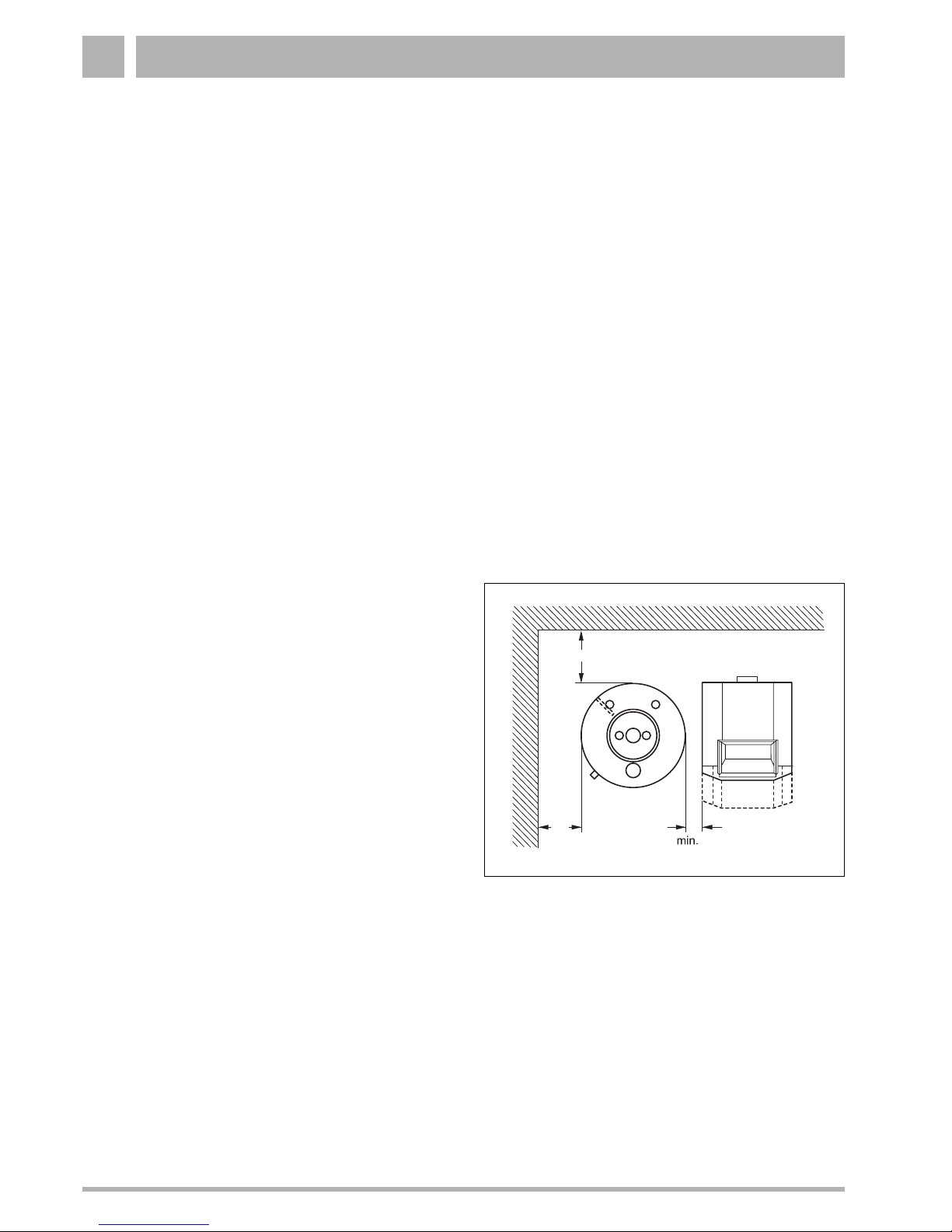
Place the tank on a level floor of sufficient strength.
Observe the recommended clearances as shown in
Fig.1. These dimensions are based on ample access for
installation and maintenance (Fig. 1). Maintain a
minimum clearance of 2“ between hot water piping or
tank surface to combustible surfaces.
16"
500
400
16"
Fig. 1 Recommended clearance for installation and
maintenance.
4"
min. 100
We reserve the right to make any changes due to technical modifications!
4
Buderus Heiztechnik GmbH • http://www.heiztechnik.buderus.de
Installation and Maintenance Instructions Logalux S 120 „US“• Issue 07/2001
Page 5
Transport 2
2 Transport
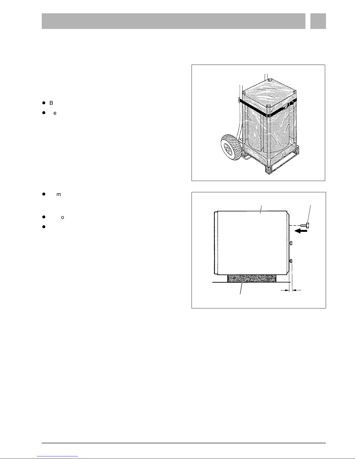
One can move the tank in its packaging as well as by
itself using a Buderus Kuli cart. (Must be ordered
separately). When using the Kuli cart, place tank on
bottom support and secure tank to the handle bars with
Kuli strap as shown in Fig. 2.
Bring the tank to its destination.
Remove plastic shrink wrap.
Fig. 2 Buderus-boiler-Kuli cart (sample picture)
Remove top styrofoam piece and wooden corner
posts. Place tank on its side on top of styrofoam
piece.(Fig. 3, Item. 1).
2 3
Remove bottom styrofoam piece from pallet.
Scew 3 M10x30 bolts in bottom of tank to serve as
tank leveling legs.(Fig. 3, Item. 3)
ca.3/4"
1
Fig. 3 Tank on top of styrofoam piece
(measurements in inches)
Item. 1: Styrofoam piece
Item. 2: Tank
Item. 3: Tank leveling bolts
We reserve the right to make any changes due to technical modifications!
Installation and Maintenance Instructions Logalux S 120 „US“• Issue 07/2001
Buderus Heiztechnik GmbH • http://www. heiztechnik.buderus.de
5
Page 6

Dimensions and Piping Connections3
3 Dimensions and Piping Connections
1
37"
37"
3/4" - 1"
3/4" - 1"
20"
20"
Fig. 4 Dimensions and piping connections (measurements in inches)
Item. 1: Magnesium Anode Rod
Model VS RS EK/AB Anode Weight*
S120 ¾" ¾" ¾" 1" 158
Tab. 1 Dimensions and connections
*dry weight.
AB: DHW outlet (short dip tube)
EK: DHW inlet (long dip tube)
VS: boiler supply
RS: boiler return
MB: temperature measuring location (sensor or aquastat)
EL: tank drain
Lbs
We reserve the right to make any changes due to technical modifications!
6
Buderus Heiztechnik GmbH • http://www.heiztechnik.buderus.de
Installation and Maintenance Instructions Logalux S 120 „US“• Issue 07/2001
Page 7

Assembly and Installation 4
4 Assembly and Installation
Level tank by adjusting the leveling bolts under the
tank (Fig. 5).
Fig. 5 Adjusting tank leveling bolts (sample picture)
4.1 Safety Requirements
TANK DAMAGE
When exceeding critical values.
ATTENTION!
Critical Values
Temperature:
Heating water (boiler) 230 °F
Domestic water (tank) 203 °F
Operating pressure:
Heating water (boiler)* 87 psi
Domestic water (tank) 145 psi
* In the overall system, it is necessary to install a boiler pressure
relief value, expansion tank and P and T valve for the tank.
One must adhere to the following
critical values for safe operation.
We reserve the right to make any changes due to technical modifications!
Installation and Maintenance Instructions Logalux S 120 „US“• Issue 07/2001
Buderus Heiztechnik GmbH • http://www. heiztechnik.buderus.de
7
Page 8

Assembly and Installation4
4.2 Tank Piping Installation
1. Install all piping and components per local and state
codes (Fig. 6).
Use threaded connections on all tank fittings. Fittings
are supplied. It is suggested to install shut off valves
in all water lines.
Install the 3/4“ brass tee fitting on the DHW outlet
connection (AB) with the teflon tape provided. Install
P and T valve (Fig. 6, Item. 2) into top of the brass
tee. Pipe the relief line full port to a nearby floor drain.
Add label to P and T relief valve stating: „Relief valve
may release water during heating of the tank“.
Install furnished 3/4“ brass couplings with teflon tape
provided on other three tappings located on top of the
tank. (See Fig. 4 for details)
Periodically test the operation of the P and T valve by
manually opening the valve.
All piping must be installed without undue stress!
Test all piping connections for leaks.
Fig. 6 Tank piping installation (sample picture)
Item. 1: Tank
Item. 2: P and T valve
Item. 3: Shut off valve with drain
Item. 4: Purge valve / vacuum breaker
Item. 5: Flow valve
Item. 6: Isolation valve
Item. 7: DHW recirculation pump (optional)
Item. 8: Pressure reducing valve (as required)
Item. 9: Test port ( as required per local code)
Item. 10:Back flow preventer ( as required per local code)
Item. 11:Pressure test port ( as required)
Item. 12:Tank drain
Safety Valve Requirements *
Minimum
Connection
Size
DN 15 (=1/2“) 200/53 255,000
*based on DIN norm 4753.
We reserve the right to make any changes due to technical modifications!
Net Water Volume
Liters/gals Btu/hr
8
AB: DHW outlet
EK: Cold feed
EZ: DHW recirc inlet
Max. Heating
Capacity
EL: Tank drain connection
Buderus Heiztechnik GmbH • http://www.heiztechnik.buderus.de
Installation and Maintenance Instructions Logalux S 120 „US“• Issue 07/2001
Page 9

Assembly and Installation 4
4.3 Temperature Control
For accurate control of the tank water temperature, one
has the option of using either the sensor supplied with
the Buderus Logamatic control or SP30D control, or the
Honeywell aquastat supplied with the S120 tank.
4.3.1 Installation of Buderus Logamatic FB Sensor
or Goldline SP30D Sensor Probe
Fully insert the suitable DHW sensor (Fig. 7, Item. 2)
together with the tension spacer (Fig. 7, Item. 1)
supplied with the tank into the factory installed tank
well (Fig. 7, Item. 3). Wire sensor leads to suitable
control terminals. (Sensor leads can be extended
using regular thermostat wiring.)
NOTICE
Ensure that the entire surface of the
sensor is in contact with the tank well.
3
2
1
Fig. 7 Installation of temperature sensor
Item. 1: Tension spacer
Item. 2: DHW tank sensor (FB sensor from Logamatic or
SP30D probe)
Item. 3: Tank dry well
We reserve the right to make any changes due to technical modifications!
Installation and Maintenance Instructions Logalux S 120 „US“• Issue 07/2001
Buderus Heiztechnik GmbH • http://www. heiztechnik.buderus.de
9
Page 10

Assembly and Installation4
4.3.2 Installation of Honeywell Aquastat
Remove cover from aquastat by removing hex head
screw on top.
Secure mounting bracket (Fig. 8, Item. 3) furnished
with tank to base of aquastat (Fig. 8, Item. 2) using
the 2 screws (Fig. 8, Item. 1). (One may need to
remove prior mounting bracket).
Insert aquastat capillary with tension spacer (Fig. 9,
Item. 4 and 5) into tank dry well (Fig. 9, Item. 3).
Secure aquastat assembly (Fig. 9, Item. 2) with 2
screws (Fig. 9, Item. 1) to the tank jacket.
2
3
1
Fig. 8 Attaching bracket to aquastat
Item. 1: Screws C-ST 4,2 × 13 mm
Item. 2: Aquastat
Item. 3: Bracket
NOTICE
Wire the aquastat into suitable control and
set desired DHW tank temperature at
aquastat.
DANGER
due to electricity.
DANGER!
Shut down main switch before working
on the boiler/tank system.
Put aquastat cover back in place.
2
3
1
4
5
Fig. 9 Installation of Honeywell aquastat
Item. 1: Sheet metal screws C-ST 4,2 × 13 mm
Item. 2: Aquastat
Item. 3: Tank dry well
Item. 4: Aquastat capillary
Item. 5: Tension spacer
We reserve the right to make any changes due to technical modifications!
10
Buderus Heiztechnik GmbH • http://www.heiztechnik.buderus.de
Installation and Maintenance Instructions Logalux S 120 „US“• Issue 07/2001
Page 11

Placing Tank in Operation 5
5 Placing Tank in Operation
Prior to start-up, verify that the tank is filled with water
and that the cold feed is functional and unrestricted.
Check all connections for leaks.
Information regarding boiler/burner operation startup can be found in their respective manuals
The complete system must be placed in operation by
the installing contractor or one of his associates in
the presence of the end user. The end user shall be
informed about start-up procedure and system operation.
We reserve the right to make any changes due to technical modifications!
Installation and Maintenance Instructions Logalux S 120 „US“• Issue 07/2001
Buderus Heiztechnik GmbH • http://www. heiztechnik.buderus.de
11
Page 12

Maintenance6
6 Maintenance
Unless specified in writing to the contrary, the S120 tank
should only be used for heating of domestic hot water.
A bi-annual inspection of the tank is recommended and
to be performed by a service technician. This inspection
involves assessing the status of the magnesium anode
rod and the need for cleaning of the tank interior.
In case of unfavorable water conditions (hard water) or
when operating the tank at high tank temperatures
(greater than 140 °F), an annual inspection is
recommended.
6.1 Testing of the Magnesium Anode Rod
DANGER
due to electricity.
DANGER!
Prior to inspection, disconnect
electricity.
Close off cold feed (EK), and drain tank. Open a
faucet at a higher location to vent the tank.
Remove plastic plugs (Fig. 10, Item. 1) from the
magnesium anode rod and clean-out opening.
Unscrew the magnesium anode rod (Fig. 10, Item. 2)
from the tank using a pipe wrench.
NOTICE
Keep surface of magnesium anode rod
free from oil or grease.
Clean surface of anode rod with water.
Check surface degradation of anode rod.
Change out the anode rod if its diameter is less than
1/2“ to 3/4“ or if its surface is severely pitted. No
corrosion protection of tank when anode rod is
severely degraded. Tank warranty is voided in this
case.
1
1
2
3
Fig. 10 Removal of magnesium anode rod
Item. 1: Plastic plugs
Item. 2: Magnesium anode rod
Item. 3: Tank inspection opening
We reserve the right to make any changes due to technical modifications!
12
Buderus Heiztechnik GmbH • http://www.heiztechnik.buderus.de
Installation and Maintenance Instructions Logalux S 120 „US“• Issue 07/2001
Page 13

Maintenance 6
6.2 Tank Cleaning
Remove tank inspection plug (Fig. 11, Item. 1) using
a 15/16“ Allen wrench.
Visually inspect tank interior and clean when
necessary. To remove scale and build-up from tank
coil, turn on boiler and tank circulator and circulate
hot boiler water through tank coil. Spray cold water
on coil surface to shock build-up from tank coil. Rinse
scale and debris form tank through tank drain.
TANK DAMAGE
due to contact with sharp objects.
ATTENTION!
Never attempt to remove coil build-up
with a sharp object, as it may damage
the tank’s protective surface coating.
Fig. 11 Removal of inspection plug
Item. 1: Inspection plug (1“)
Item. 2: Inspection and clean-out opening
1
2
6.3 Recommissioning after Tank Cleaning
Install magnesium anode rod (Fig. 10, Item. 2). Use
quality teflon tape for sealing. Wrap generously.
Install inspection plug (Fig. 11, Item. 1). Use quality
teflon tape for sealing. Wrap generously.
Place system back in operation.
Check all connections for leaks.
Put plastic plugs (Fig. 10, Item. 1) back in place on
magnesium anode and inspection plug.
We reserve the right to make any changes due to technical modifications!
Installation and Maintenance Instructions Logalux S 120 „US“• Issue 07/2001
Buderus Heiztechnik GmbH • http://www.heiztechnik.buderus.de
13
Page 14

Parts Break-down for S120 Tank7
7 Parts Break-down for S120 Tank
Item.-Nr. in
Fig. 12
Page 15
5 Indirect fired hot water tank S120 „US“ complete. 6320 5018 1
Available individual parts:
10 Magnesium anode rod D26 × 505 mm, G1“ 3868 538 1
20 Inspection plug 6790 1380 1
30 Aquastat mounting bracket 6301 3510 1
40 Tank top cover, blue 6301 3260 1
50 Tank top screws, DIN 7981-C-ST6,3 × 19 - A3T x 2
60 Tension spacer 7099 268 1
70 Fill and drain valve (German model) 479 762 1
80 Plastic plugs, blue 6301 3463 2
90 Hexhead bolts, ISO 4017- M10 × 30 - 8.8 - A3K x 3
100 DHW outlet dip tube, 3“ long 5222 171 1
110 DHW inlet dip tube, 32“ long 5222 173 1
Tab. 2 Spare Parts for S120
Part Description Part-Nr. Quantity
We reserve the right to make any changes due to technical modifications!
14
Buderus Heiztechnik GmbH • http://www.heiztechnik.buderus.de
Installation and Maintenance Instructions Logalux S 120 „US“• Issue 07/2001
Page 15

Parts Break-down for S120 Tank 7
5
80
10
80
100
50
20
50
40
110
60
Fig. 12 Spare Parts for S120
We reserve the right to make any changes due to technical modifications!
Installation and Maintenance Instructions Logalux S 120 „US“• Issue 07/2001
30
70
90
Buderus Heiztechnik GmbH • http://www.heiztechnik.buderus.de
15
Page 16

Boiler installed by:
(contractor’s address)
Boiler installed on:
(date of installation)
Buderus Hydronic Systems
50 Wentworth Avenue
Londonderry, NH 03053 USA
Tel: (603) 552-1100 • Fax: (603) 421-2719
www.buderus.net
Buderus Hydronic Systems, Inc. reserves the right to make changes without notice due to continuing
engineering and technological advances.
 Loading...