

Page 1

7216 1800 - 02/2006 GB (EN) for the installer
Installation instructions
ModuLink 250 RF - Twin channel modulating
programmable room thermostat
Please read thoroughly before installing the unit.
See boiler installation instructions for more details
CH
10:41
am
pm
auto
off
on
auto
on
off
20
˚C
5
HW
24 Volt only
Page 2
Installation instructions ModuLink 250 RF – twin channel
2 Buderus
Installation, maintenance and repair must be
carried out by a competent person (e.g.
Corgi Registered) and in accordance with
current IEE wiring regulations.
The twin channel ModuLink can be fitted on all
Buderus or Buderus appliances with an external
control unit from the following types:
UBA1.5, UBA3.0 and DBA.
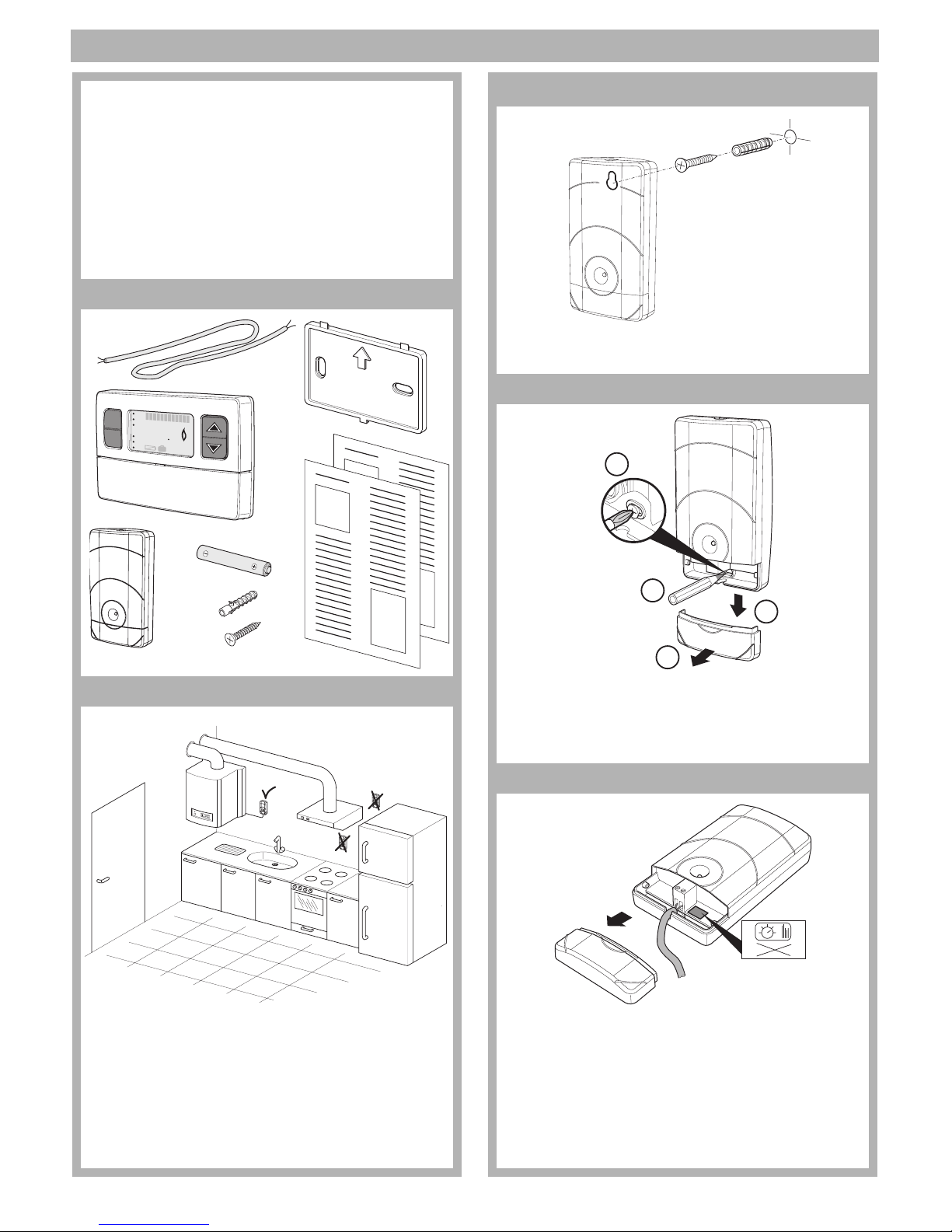
1 Contents of package
2 Installing the receiver
Install the receiver as suggested in the installation instruction of the boiler.
If you encounter interference problems, then
install the receiver away (30 cm is advised) from
the boiler or other metal objects including wall
boxes.
4 x
2 x
CH
10:41
am
pm
auto
off
on
auto
on
off
20
˚C
5
HW
3
Drill a hole, insert the plug and mount screw.
Place receiver over the mounted screw.
4
Remove casing (1 and 2). Mark the hole (3) for
the second screw with a pencil. Remove the
receiver, then drill a hole for the plug. Refit the
receiver and mount the screw (4).
5
Attach cable (not thicker than 2.5 mm
2
) to the
receiver. The wires are not polarity sensitive.
Attach the cable to the boiler. See installation
instructions of the boiler for more information.
Warning! DO NOT connect the cable to
230V. When installed correctly a green LED
appears on the receiver.
1
2
3
4
230V
Page 3

Installation instructions ModuLink 250 RF – twin channel
Buderus 3
6 Installing the room thermostat
The room thermostat should be installed in:
- in an open space
- in the main living area
- on an inside wall
- away from light and heat source
- away from RF interference
- away from direct draughts
- away from damp and condensate
- away from large metal surfaces
- at least 1m away from electrical equipment.
Due to the building regulations the thermostat
should not be placed in an area with TRV (temperature radiator valves).
7
Attach the wall bracket (1) to the wall and click
on the thermostat (2).
1.50 m
2
1
8
Place the batteries in the room thermostat.
9Start up
There is no requirement to setup the RF link
between the thermostat and receiver. This has
been completed as part of the manufacturing
process. The room thermostat sends a signal to
the receiver at least every 30 minutes to see if
they are still in contact with each other.
A green LED can be seen on the receiver.
If you want to test whether you have reception
throughout the house then press the button
on the thermostat for more than 5 sec. It will
now send out a signal continuously (The LED
on the receiver flashes green and the thermostat shows connecting in the display). Walk
around the house with the thermostat to check
the reception. Maximum signal range is approximately 30 meters. Range may decrease
according to building wall construction.
Someone will need to stay with the receiver.
The LED on the receiver will turn red (stops
flashing) when the thermostat is out of reach.
Reposition the receiver if necessary for better
reception. The receiver will stay in this test
mode until the button on the thermostat is
pressed.
m
ok
CH
HW
10:41
am
pm
auto
off
on
auto
on
off
20
˚C
5
CH
10:41
am
pm
auto
off
on
auto
on
off
20
˚C
5
HW
Page 4

Installation instructions ModuLink 250 RF – twin channel
721.618A - 4612 - 02/2006
10 Communication loss
When there is a communication loss for longer
than 35 minutes, then the LED of the receiver
will turn red. What to do:
– Check the batteries (2 x 1.5V - AA - Alkaline
batteries) of the thermostat and change them
if necessary.
– Make sure that the room thermostat is within
reach of the receiver.
11 Temporary manual override
When there is a communication loss it is possible to manually override the thermostat.
To override the thermostat press the button on
the receiver.
Keep in mind that the boiler will now operate
continuously (until the button on the receiver is
pressed or until communication has been
restored) according to the set flow temperature.
Adjust the flow temperature of the boiler if so
desired.
The LED on the receiver will be intermittent red
and green during the manual override.
12 RF link - reconnecting
When one component has been replaced (e.g.
receiver), then it is necessary to restore the
communication by entering the RF link connecting mode. Make sure that the thermostat is
within reach of the receiver.
Press on the thermostat for longer then
5 seconds. The thermostat's display will now
show a rotating dash while connecting.
The receiver LED flashes green. Press the button on the receiver to accept the connecting to
the thermostat. The LED on the receiver is now
continuously green.
Press the button on the thermostat to stop
the thermostat's connecting mode.
13 Spare Parts
14 Regulations
EC directives:
Related Standards:
BS EN607730-1
part order no.
wall bracket
NE 18212
receiver
NE 18211
thermostat
NE 18210
Low Voltage Directive (73/23/EEC)
Electro Magnetic Compatibility
Directive (89/336/EEC)
CE Marking Directive (93/68/EEC)
Buderus
Cotswold Way, Warndon,
Worcester, WR4 9SW
Telephone: 01905 - 752 936
Fax: 01905 - 753 130
Customer Services: Tel: 0870 - 421 5933
Technical Product Support: Tel: 0870 - 421 5944
Sales: Tel: 01905 - 752 640 Fax: 01905 - 456 445 /
455 394
Returns: Tel: 01905 - 752 531 Fax: 01905 - 455 392
Spares: Tel: 01905 - 752 576 Fax: 01905 - 754 620
www.buderus-domestic.co.uk
Buderus is a trading name of
BBT Thermotechnology UK Ltd.
CH
10:41
am
pm
auto
off
on
auto
on
off
20
˚C
5
HW
W
 Loading...