

Page 1
For heating contractors
Pour le professionel
Please read carefully before
installing and servicing
A lire attentivement avant le
montage et l’entretien
MCM10
6 720 617 648 - 07.1O
en-us Installation Instructions 2
fr Notice d´installation 20
6 720 616 690 (08/2009)
Page 2
Table of contents
MCM10
2
Table of contents
1 Explanation of symbols and safety instructions 3
1.1 Symbols, explanation of 3
1.2 Safety instructions 3
2 Details about the MCM10 module 4
2.1 Declaration of conformity 4
2.2 Information regarding the documentation 4
2.3 Proper use 4
2.4 Scope of delivery 4
2.5 Accessories 4
2.6 Technical specifications 5
2.6.1 General 5
2.6.2 Dimensions 5
2.6.3 Power connection parameters 5
2.6.4 Measurement values supply temperature sensor 5
2.6.5 Measurement values outdoor temperature sensor 5
2.7 System integration of the MCM10 6
2.7.1 Principles of cascade control 6
2.7.2 Heating controls for MCM10 cascade systems 6
2.7.3 Water heating with MCM10 cascade systems 6
2.7.4 Internal frost protection function 6
2.7.5 Control of one heating pump 7
2.7.6 External switching contact 7
2.7.7 System versions overview 7
2.7.8 Connection of additional modules in case of heating
system controls with 2-wire BUS control 9
3 Installation 10
3.1 Installation 10
3.1.1 Wall mounting 10
3.2 Making the electrical connections 11
3.2.1 Connection of the low voltage part with BUS
connections 11
3.2.2 120 V AC connection 11
3.2.3 Connection of a remote fault indication with optical
and acoustic signal 12
3.2.4 Electrical connection of the outdoor temperature
sensor 12
3.2.5 Electrical connection of the supply temperature
sensor 12
3.2.6 Electrical connection of the external switching
contact 12
3.2.7 Disposal 12
3.3 Installing other accessories 12
4 Start-up and shut-down 13
4.1 Configuration 13
4.2 Commissioning 13
4.3 Configuration reset 13
4.4 Shutting down 13
5 Operating and fault indications 14
5.1 Operating and fault indications via the heating appliance
displays 14
5.2 Fault message via the remote fault indication 14
5.3 Operating and fault indications via LED 14
5.4 Operating and fault indications via the RC35 16
5.5 Replacing the fuse for the heating zone pump
connection 17
6 Environmental protection 18
7Appendix 19
Page 3
1
Explanation of symbols and safety information
MCM10
3
1 Explanation of symbols and safety information
1.1 Explanation of symbols
Warning symbols
Signal words indicate the seriousness of the hazard in
terms of the consequences of not following the safety
instructions.
• NOTICE indicates possible damage to property or
equipment, but where there is no risk of injury.
• CAUTION indicates possible injury.
• WARNING indicates possible severe injury.
• DANGER indicates possible risk to life.
Important information
Additional symbols
1.2 Safety precautions
B To ensure proper function, follow these instructions.
B Install and start up the heating appliance and all
accessories according to the associated instructions.
B Use this accessory exclusively in conjunction with the
controllers and heating appliances listed. Follow the
connection diagram!
B This accessory has inputs and outputs with different
voltages. Never connect the low voltage side to the
120 V power supply or vice-versa.
B In case of wall installation: never install this accessory
in wet areas.
B Work on electrical components only if you have the
required training and qualification.
B Before you start working on the system, disconnect the
heating system from electrical power by shutting off the
emergency shut-off switch or the heating system circuit
breaker.
B Secure against unintentional reconnection.
B It is not sufficient to simply shut off the controls.
B Observe all applicable electrical codes and
regulations.
Safety instructions in this document are
framed and identified by a warning triangle
which is printed on a grey background.
Electrical hazards are identified by a lightning
symbol surrounded by a warning triangle.
Notes contain important information in cases
where there is no risk of personal injury or
material losses and are identified by the
symbol shown on the left. They are bordered
by horizontal lines above and below the text.
Symbol Meaning
B a step in an action sequence
Æ a reference to a related part in the docu-
ment or to other related documents
•a list entry
– a list entry (second level)
Page 4
2
Details about the MCM10 module
MCM10
4
2 Details about the MCM10 module
2.1 Declaration of conformity
2.2 Information regarding the
documentation
We reserve the right to make technical modifications!
2.3 Proper use
The MCM10 modules are designed to control cascade
systems. A cascade system is a heating system where
several smaller heating appliances are connected in
parallel to achieve a higher output (Æ Fig. 12, page 19).
The MCM10 modules are only suitable for controlling
heating appliances with Logamatic EMS BUS.
For floor-standing heaters, the MCM10 module is only
suitable for the activation of gas heaters with modulating
burners without operating conditions.
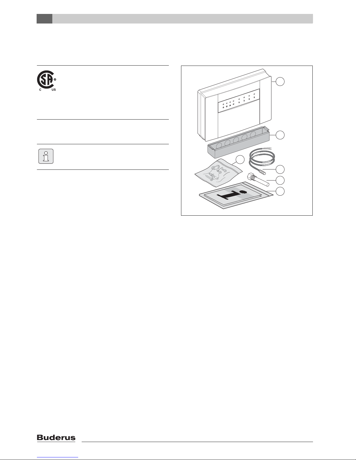
2.4 Scope of delivery
Fig. 1 Scope of delivery
1 MCM10
2 Duct connection box
3 Sensor well
4 Supply temperature sensor FV
5 Package with:
- 3 screws and 3 wall-plugs
- 4 strain relief clips and 8 screws
6 Installation and operating instructions
B Check that the delivery is complete.
2.5 Accessories
Here is a list with typical accessories. In order to get a
complete overview of all available accessories, please
contact the manufacturer.
• Outdoor temperature sensor FA for connection to
terminal F (only for system variant 1).
• RC35: Outdoor reset heating system controls with
plaintext display for controlling a heating system with
mixed or unmixed heating zones.
• WM10: Low loss header module for EMS.
• MM10: Mixer module for EMS.
• AM10: Outdoor reset controller with thermostat
connection.
The design and operation of this product
conform to the U.S. and Canadian Directives.
Its conformity is demonstrated by the CSA
designation.
The Declaration of conformity can be
claimed. See the address at the back of this
manual.
Hand all enclosed documents over to the user.
6 720 616 690-02.1TD
1
2
4
3
6
5
Page 5
2
Details about the MCM10 module
MCM10
5
2.6 Technical specifications
2.6.1 General
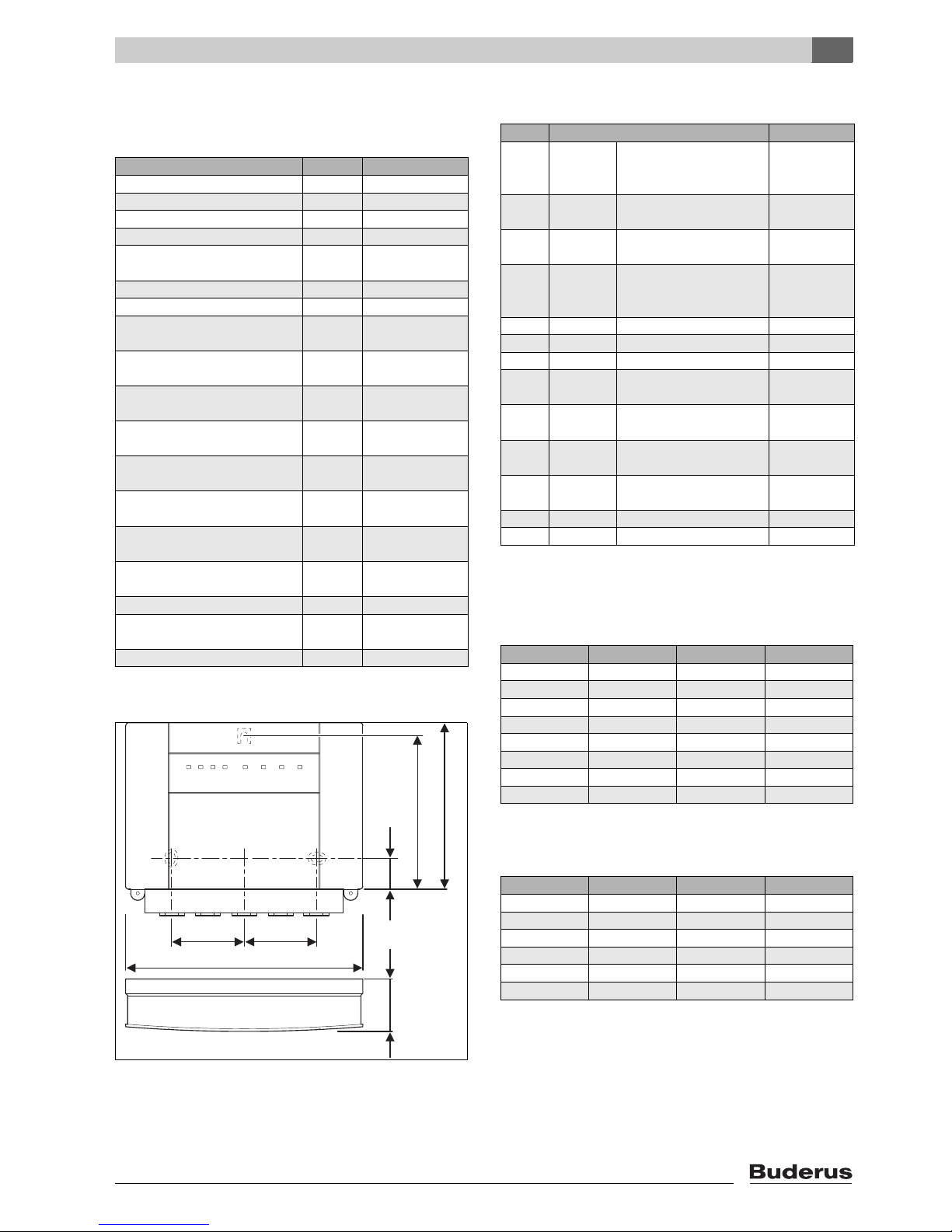
2.6.2 Dimensions
Fig. 2 Dimensions
2.6.3 Power connection parameters
2.6.4 Measurement values supply temperature
sensor
2.6.5 Measurement values outdoor temperature
sensor
Designation Unit
Dimensions (Æ Fig. 2)
Weight (without packaging) lb (kg) 1.76 (0.8)
Rated voltage MCM10 AC … V 120
Frequency Hz 60
Max. on-site fuse protection of the
input voltage
Amp 10
Power draw MCM10 W 5
Rated voltage BUS DC … V 15
Internal appliance fuse, heating
pump output
Amp 5 AF, ceramic, filled
with sand
Measuring range, supply
temperature sensor
° F ( °C) 32 … 212
(0 … 100)
Measuring range, outside
temperature sensor
° F ( °C) – 40 … 122
( – 40 … 50)
Permissible ambient
temperature MCM10
° F ( °C) 32 … 122
(0 … 50)
Permissible ambient temperature,
supply temperature sensor
° F ( °C) 32 … 212
(0 … 100)
Permissible ambient temperature
outdoor temperature sensor
° F ( °C) – 58 … 212
( – 50 … 100)
Maximum cable length,
2-wire BUS connections
ft (m) (ÆTab. 6, page 11)
Maximum lead lengths,
sensor leads
ft (m) (ÆTab. 7, page 11)
EMC suppression level to IEC 60730
Enclosure rating II in accordance
with IEC 60730
NEMA definition Type 2
Tab. 1 General
2-1/2" (62mm)
6 720 616 690-03.1TD
2-1/2" (62mm)
9-1/4" (235mm)
2-1/4" (58mm)
1-1/2" (37mm)
5-9/16" (142mm)
6-1/2" (165mm)
Pos.
1)
1) (Æ Fig. 12, page 19)
Interface
A Input Power supply from the power
line or from the previous module MCM10
120 V AC,
max. 10 Amp.
B Output Power supply for additional
MCM10
120 V AC,
max. 10 Amp.
C Output Pump 120 V AC,
max. 250 W
D Output Remote fault indication zero volt,
max. 120 V,
2Amp.
E Input Supply temperature sensor NTC (ÆTab. 3)
F Input Outdoor temperature sensor NTC (ÆTab. 4)
G Input External switching contact Zero volt
H Input Heating controls
(ON/OFF contact)
24 V DC
I Input Heating controls (propor-
tional interface)
0-10 V DC
J 2-wire BUS to the heating controller
(RC35, WM10, MM10)
–
K 2-wire BUS from the previous MCM10
module
–
L 2-wire BUS to the next MCM10 module –
M 2-wire BUS to the heating appliance –
Tab. 2 Power connection parameters
°F ( °C) Ω °F ( °C) Ω
68 (20) 12490 140 (60) 2488
77 (25) 10000 149 (65) 2083
86 (30) 8057 158 (70) 1752
95 (35) 6531 167 (75) 1481
104 (40) 5327 176 (80) 1258
113 (45) 4369 185 (85) 1072
122 (50) 3603 194 (90) 917
131 (55) 2986 203 (95) 788
Tab. 3 Measurement values supply temperature sensor
°F ( °C) Ω °F ( °C) Ω
– 4 ( – 20) 97070 50 (10) 19900
5 ( – 15) 72929 59 (15) 15708
14 ( – 10) 55330 68 (20) 12490
23 ( – 5) 42315 77 (25) 10000
32 (0) 32650 86 (30) 8057
41 (5) 25388 95 (35) 6531
Tab. 4 Measurement values outdoor temperature
sensor
Page 6
2
Details about the MCM10 module
MCM10
6
2.7 System integration of the MCM10
2.7.1 Principles of cascade control
When the heating appliance generates a heat demand
(Æ Tab. 5, system versions 1, 2, 3, and 4), initially one
heating appliance is started and, if required, its heat
output is raised to its maximum nominal power. Only then
will another heating appliance be started.
If excessive heat is being generated, heating appliances
are controlled one after another in sequence without
delay down to their respective minimum nominal power,
and then shut down until heat demand and generation
match. With system version 4 all appliances are shut
down simultaneously.
The MCM10 module automatically determines the
sequence in which the heating appliances are controlled.
The MCM10 module safeguards an even distribution of
the burner hours of operation for all heating appliances.
This takes into account heating and DHW. This increases
the heating appliance service life. If the power supply to
the MCM10 module is interrupted, the hours run meters
in the MCM10 module are reset to zero.
As soon as a heating appliance is not able to start (DHW
heating for a directly-connected hot water tank, heating
appliance fault, communication fault with MCM10
module), another heating appliance will be started
automatically to cover the heat demand.
2.7.2 Heating controls for MCM10 cascade
systems
The MCM10 modules stage the heating appliances
based on the heat demand calculated. For control
according to the heat demand, the MCM10 modules
always require heating system controls (Æ Fig. 12,
terminals H, I or J, page 19). Depending on the heating
system controls, there are four possible system versions
(ÆTab. 5).
One MCM10 module can control up to four heating
appliances. By connecting up to four MCM10 modules,
up to 16 heating appliances can be linked to form a single
cascade (Æ Fig. 12, page 19). In this case, one MCM10
module controls the cascade (MCM10 master).
Depending on the heating system controls used, a
cascade system with up to 4 or up to 16 heating
appliances can be created. The maximum number of
heating appliances that can be connected and the
number of MCM10 modules required for the different
systems are shown in Tab. 5, page 8.
The MCM10 module controls the entire boiler loop
(primary loop including the low loss header). All other
heating system components (secondary side of the low
loss header, such as the heating zones, hot water tank)
can be regulated by a weather-dependent heating
controller with a 2-wire BUS interface and additional
modules (WM10, MM10...). Contact the manufacturer for
further details. You will find the relevant address on the
back cover.
Heating appliances of any output can be part of a
cascade.
2.7.3 Water heating with MCM10 cascade
systems
Hot water tanks can be connected hydraulically and
electrically directly to a heating appliance (storage tank
model).
• Water heating is controlled by the heating appliance.
During a DHW demand, this heating appliance will not
be called by the MCM10 module. In case of demand,
another heating appliance may be started.
• If water heating is timed using a heating system control
with 2-wire BUS connection, the heating appliance
with the storage tank must be connected to the
MCM10 module (master) via terminals 17 and 18.
2.7.4 Internal frost protection function
The MCM10 module is equipped with an internal frost
protection function: if the supply temperature falls below
45 °F ( 7 °C ), a heating appliance starts and runs until a
supply temperature of 60 °F (15 °C) has been achieved.
Any heating pump that is connected to the MCM10
module will also run (Æ paragrahp 2.7.5).
B Connect the supply temperature sensor to the MCM10
master module if the internal frost protection function is
required.
Note that, for the correct function, only one
heating system control/building management
system may be connected.
The different system versions require the
connection of certain accessories (supply
temperature sensors, outdoor temperature
sensors, heating pumps, and heating system
controls) (Æ Tab. 5, page 8).
If the user wants to prepare hot water using
the 3-way valve of the heating appliance and
he wants to continue supplying the heating
zone, he must switch off the warm water
priority on the RC35 for all heating zones
since with the factory settings, hot water
priority is active by default.
The frost protection function of heating
system controls with 2-BUS interface
provides comprehensive system frost
protection. This requires the connection of an
outdoor temperature sensor.
Page 7
2
Details about the MCM10 module
MCM10
7
2.7.5 Control of one heating pump
In heating systems with only one heating zone, the heating
pump can be connected directly to the MCM10 module
(master).
The heating pump runs:
• as long as at least one heating appliance pump is
running (if required, set the pump run-on time on the
heating appliance accordingly Æ heating appliance
installation instructions); or
• briefly after remaining idle for 24 hours (anti-seizing
protection).
2.7.6 External switching contact
The MCM10 module is equipped with an external
switching contact (Æ Fig. 12, pos. G). For the
characteristics of this switch, see Æ Tab. 2, page 5.
This external switching contact can be used optionally,
e.g. to connect a temperature switch for protecting the
radiant floor heating against a too-high water temperature.
If the switching contact is opened, all heating appliances
are switched off via the MCM10 module. As soon as the
switching contact is closed again, the heating appliances
are ready for operation again.
2.7.7 System versions overview
As a manufacturer of advanced heating technology, we
give high priority to the development and manufacture of
economical and clean-burning heating appliances. To
guarantee this, our heating appliances are equipped with
modulating burners. To make optimum use of the burner
characteristics, heating system controls with 2-wire BUS
control should be used.
The anti-seizing pump protection lets the
heating pump run at least once every day
even without a heat demand (e.g. during
summer).
B Leave your heating system switched on all
year to prevent the pump (in summer) from
seizing up.
Page 8

2
Details about the MCM10 module
MCM10
8
System version 1: Modulating weathercompensated heating controller (RC35)
An advantage of this system is the ability of the modules
to communicate, enabling all heating zones to be
controlled (function module WM10 or MM10) with the
MCM10 module via a common BUS, parallel to terminal J
on the MCM10 module (Æ Fig. 12, page 19). This
ensures matching generated heat amount to the actual
heat demand of all heating zones in the system. With this
version, the heating system achieves optimum comfort
with maximum energy savings.
System version 2: Modulating weathercompensated heating controller (AM10)
The supply target temperature of the AM10 module
depends on the outdoor temperature. In contrast to
system version 1, it is not possible to use the WM10 and
MM10 modules.
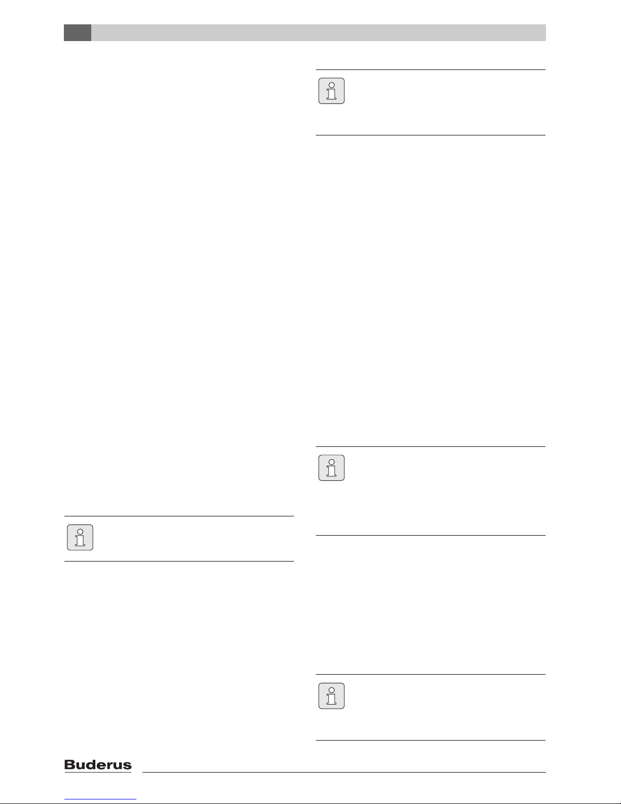
System version 3: Modulating 0 - 10 V controller,
regulated acc. to output
In conjunction with a building management system with
0 - 10 V interface, the total output of the cascade can be
selected as control variable. Setting is achieved via a
jumper (Æ Fig. 3).
System version
Symbol forcontroller
connection
Heating controller to MCM10
master module
Type
Max. number MCM10
Max. number of heating
applianceswith BUS-enabled
Logamatic EMS
Required accessories with connection to MCM10
(Æ Fig. 12, page 19)
1 Modulating weather-compensated
controller 2-wire BUS control
RC35 4 16 • Outdoor temperature sensor.
• One WM10 module. The WM10 module is delivered with a
supply temperature sensor (see explanation on the following
page).
• Heating pump (secondary zone) is connected to the WM10
module.
2 Modulating weather-compensated
controller 2-wire BUS control
AM10
weathercompensated controller
4 16 • Connect outdoor temperature sensor to AM10.
• Common supply temperature sensor on terminal E (only for
internal frost protection).
• Heating pump (secondary zone) (Æ Fig. 12, [19]) on terminal C, only in case of one or several heating zones without
heating pump or in case of heating zones that do not communicate via BUS modules with the MCM10module.
3 Modulating
0 - 10 V controller,e.g. building management system;
control of the heat output
Any 4 16 • Common supply temperature sensor on terminal E (only for
internal frost protection).
• Heating pump (secondary zone) (Æ Fig. 12, [19]) on
terminal C, only with one or several heating zones without
heating pump or with heating zones that are not regulated
via the building management system.
4 Modulating
0 - 10 V controller, e.g. building management system;
supply temperature control
Any 4 16 • Common supply temperature sensor on terminal E
• Heating pump (secondary zone) (Æ Fig. 12, [19]) on
terminal C, only with one or several heating zones without
heating pump or with heating zones that are not regulated
via the building management system.
5 ON/OFF controller (zero volt) Any 4 16 • Common supply temperature sensor on terminal E (only for
internal frost protection).
• Heating pump (secondary zone) (Æ Fig. 12, [19]) on
terminal C.
Tab. 5 System versions overview
0 ... 10V
0 ... 10V
Page 9
2
Details about the MCM10 module
MCM10
9
Fig. 3 Setting via jumper
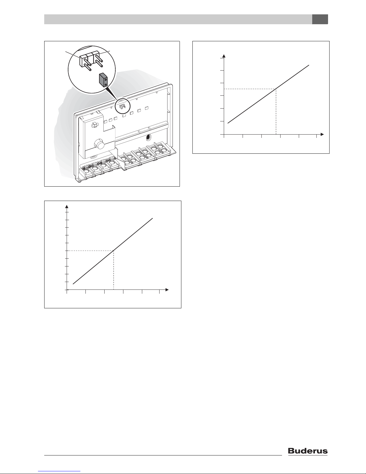
Fig. 4 Correlation between the input voltage and heat
output
U Input voltage
P Output in % of the rated cascade output
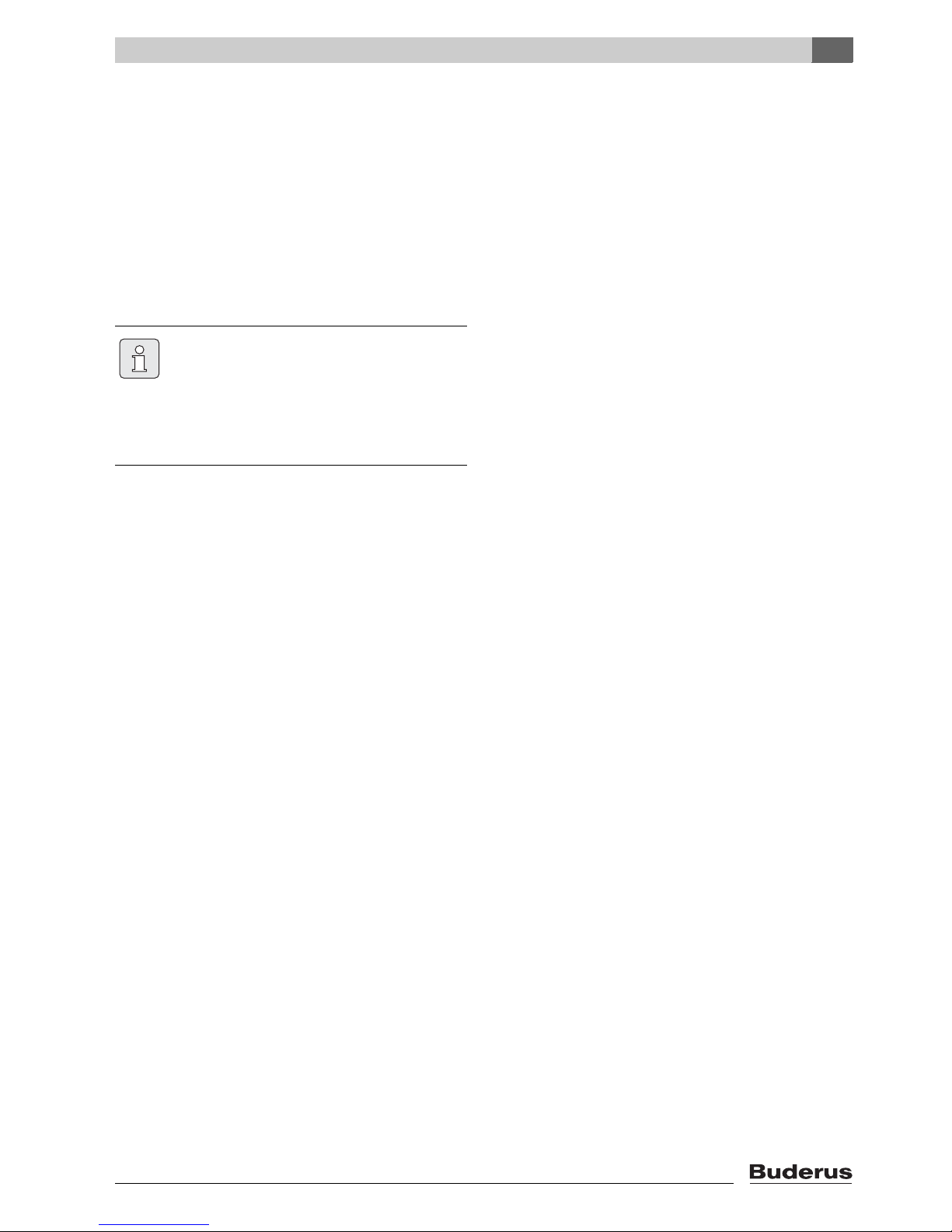
System version 4: Modulating 0 - 10 V controller,
regulated to supply temperature
In conjunction with a building management system with
0 - 10 V interface, the supply temperature can be
selected as control variable. Setting is achieved via a
jumper (Æ Fig. 3).
Fig. 5 Correlation between the input voltage and the
supply temperature
U Input voltage
VT Supply temperature
System version 5: Heating control with ON/OFF
contact
In conjunction with a control unit with ON/OFF contact,
module MCM10 regulates the cascade output in
accordance with the contact closure respectively up to
maximum output, by starting one appliance after another.
When the contact is opened, all heating appliances are
shut down simultaneously.
The ON/OFF contact of the heating system controls must
be a dry contact.
2.7.8 Connection of additional modules in case of
heating system controls with 2-wire BUS
control
Any additional modules, such as the WM10 and MM10
modules (Æ Fig. 12, [21], page 19), must be connected
to the BUS of the heating controller (parallel to terminal J
on the MCM10 module).
6 720 617 648-001.1TD
VT [˚F]
P [%]
0246810
6 720 617 648-09.1TD
0
30
50
70
90
U [V DC]
P [%]
194 (90)
167 (75)
140 (60)
113 (45)
86 (30)
59 (15)
0
0246810
6 720 617 648-10.1TD
U [V DC]
[˚F (˚C)] VT
Page 10
3
Installation
MCM10
10
3 Installation
3.1 Installation
3.1.1 Wall mounting
B Determine the location on the wall in accordance with
the dimensions of the MCM10 module.
B Determine whether the main power cord is laid in stiff
or flexible ducts that require duct connection box and
appropriate free space under the MCM10.
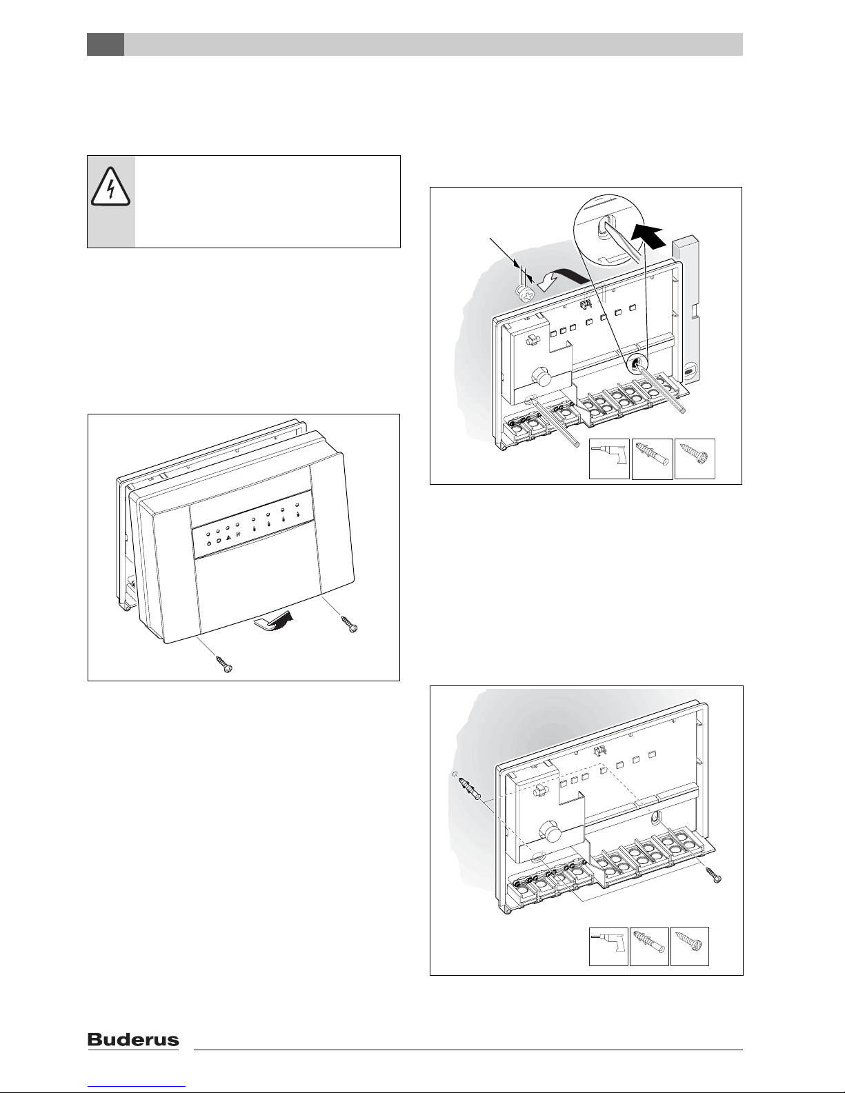
B Undo two screws at the bottom of the MCM10 module,
pull the cover at the bottom forward and lift off upwards
(Æ Fig. 6).
Fig. 6 Removing the cover
B For the upper attachment screw, drill a Ø 1/4" (6 mm)
hole, insert an appropriate wall anchor, and insert the
screw until only 1/16" (1.5 mm) protrudes (Æ Fig. 7).
Fig. 7 Upper attachment screw
B In the back panel of the MCM10 module, create two
holes for the lower attachment screws using the
breakouts prepared.
B Attach the MCM10 module at the top attachment
screw.
B Mark the holes to be drilled on the wall through the
breakouts created.
B Remove the MCM10 module.
B Drill Ø 1/4" (6 mm) holes and insert wall anchors
(Æ Fig. 8).
Fig. 8 Insert wall anchor
DANGER: Risk of electric shock!
B Before connecting the power supply,
interrupt the power supply to the heating
appliances and to all other BUS
subscribers.
7 746 800 090-03.1O
1/4"
3,5 mm
0.05" (1,5mm)
6 720 617 648-02.1O
3.
4.
4.
2.
1.
1/4"
1/4"
3,5 mm
6 720 617 648-03.1O
1/4"
1/4"
Page 11
3
Installation
MCM10
11
B Hook in the MCM10 module at the top attachment
screw and secure with the two lower screws.
B With the use of stiff or flexible ducts:
– Remove all plastic grommets from the slits on the
lower side of the MCM10;
– push the duct connection to the intended place;
– break out the required number of cable entries by
knocking cautiously with a screwdriver handle;
– mount the duct according to the manufacturer's
instructions.
Note: When using ducts, no plastic grommets are
required.
3.2 Making the electrical connections
B Observe electrical code for the connection and use at
least cable AWG14 for the main power cord.
B Always route cables through the preassembled
grommets and apply the strain relief supplied to protect
the system against the ingress of dripping water.
B Wiring preferably with single core cable. When using
multi-strand (flexible) cables, fit them with wire ferrules.
B Cables can be pulled off the contact strip for their
connection to the screw terminals. The connectors are
color-coded and keyed to prevent mismatch of cable
terminals.
3.2.1 Connection of the low voltage part with
BUS connections
The minimum permissible cable cross-section of the 2wire BUS connection arises from the cable length:
B Route all low-voltage cables separately from cables
carrying 120V to avoid inductive interference (minimum
separation 4 inches)(100 mm).
B In case of inductive external influences, use shielded
cables.
This way, the cables are screened against external
influences (e.g. high-voltage cables, contact wires,
transformer stations, radio and TV devices, amateur
radio stations, microwave devices, etc.).
B When sensor leads are extended, apply the following
lead cross-sections:
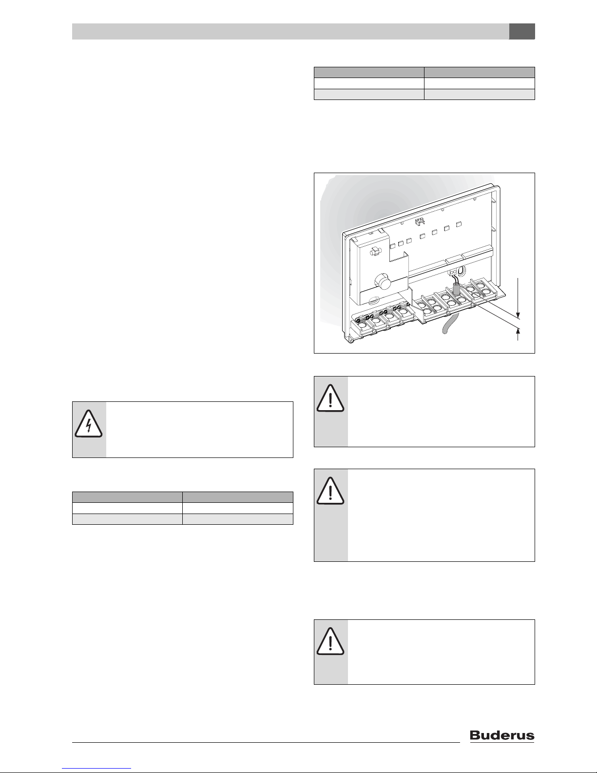
B To safeguard the splash-proof rating (IP):
Route cables so that the cable sheath protrudes at
least 0.8" (20 mm) into the cable grommet (Æ Fig. 9)
or the duct connection box.
Fig. 9 Splash-proof
3.2.2 120 V AC connection
B Only use electric cable of similar quality.
B Never connect additional controllers that regulate other
system components to outputs C (pump) and D (fault
signal).
CAUTION: Malfunction!
B Always wire in accordance with the wiring
diagram (Æ Fig. 12, page 19).
B Never connect one BUS to another.
Cable length Min. cross-section
< 325 ft (100 m) AWG 20
325 - 650 ft (100 - 200 m) AWG 18
Tab. 6 Minimum permissible cross-section of the
2-wire BUS connections
Cable length Min. cross-section
< 65 ft (20 m) AWG 20
65 - 100 ft (20 - 30 m) AWG 18
Tab. 7 Sensor lead extension
CAUTION: Risk of pole reversal.
Malfunction through interchanged
connection on the 0 - 10 V interface.
B Ensure connection to the correct poles
(9 = negative, 10 = positive).
CAUTION: The MCM10 module input is not
fuse-protected.
Overloading the outputs can damage the
MCM10 modules.
B Protect the MCM10 module power supply
(master) with a fuse with maximum rating
10 Amp.
CAUTION: Output C (pump) of the MCM10
module has a maximum load capacity of
250 W.
B Connect pumps drawing more current via
relays.
6 720 617 648 - 04.1O
≥1" (25 mm)
Page 12
3
Installation
MCM10
12
B Recommendation when using several MCM10
modules (cascade with more than four heating
appliances): Provide the additional modules with
power via the first MCM10 module (master). This
ensures simultaneous start-up.
3.2.3 Connection of a remote fault indication with
optical and acoustic signal
For example, a fault indicator can be connected to the
zero volt fault contact (Æ Fig. 12, terminal D, page 19).
The state of the fault contact is also indicated via an LED
on the MCM10 (Æ Tab. 9, page 14).
This is a dry contact that carries a maximum current of 2 A
at 120 V AC.
3.2.4 Electrical connection of the outdoor
temperature sensor
In conjunction with heating system controls with 2-wire
BUS control, always connect outdoor temperature sensor
to the MCM10 module (master) (Æ Fig. 12, page 19) and
not to the heating appliance.
3.2.5 Electrical connection of the supply
temperature sensor
For system version 1, the common supply temperature
sensor must be connected to the WM10 (Æ installation
instructions for WM10) and for the system versions 2, 3,
4, and 5, to the MCM10, terminal E (Æ Fig. 12, [18],
page 19).
3.2.6 Electrical connection of the external
switching contact
If an external switching contact must be connected, the
bridge on the plug must be removed first.
3.2.7 Disposal
B Dispose of packaging in an environmentally-
responsible manner.
B When replacing components, dispose of the old parts
in an environmentally-responsible manner.
3.3 Installing other accessories
B Install accessories according to the legal requirements
and the installation instructions supplied with them.
B The BUS subscribers RC35, WM10, and MM10 must
be connected to terminal J (Æ Fig. 12, page 19).
The maximum current drawn by the system
components (pump, etc.) must not exceed
specifications (Æ Tab. 2, page 5).
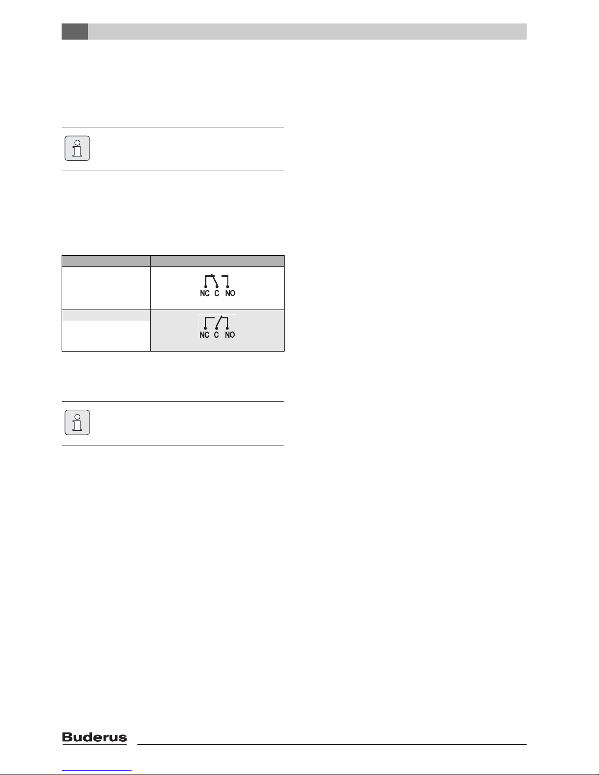
Situation Operating status contact
Current on, no fault
Current on, fault
No current
Tab. 8 Operating status contact
The remote fault indication is enabled when
the power supply to the MCM10 module is
interrupted (master) (function check).
Page 13

4
Start-up and shut-down
MCM10
13
4 Start-up and shut-down
4.1 Configuration
With this configuration, the control characteristics of the
MCM10 module (master) are adapted to the specific
heating system.
The MCM10 module is configured automatically:
• during the first start-up of a MCM10 module,
• during a restart following a reset of the configuration
(Æ paragrahp 4.3).
Configuration takes at least five minutes. During
configuration, the LEDs associated with the connected
heating appliances and possibly the LED to indicate BUS
communication (Æ Tab. 9) flash. Configuration is
completed and saved to the MCM10 when LEDs stop
flashing.
Any configuration saved remains in the memory, even in
case of power failure.
If, after configuration, a heating appliance (or a MCM10
module) is temporarily shut down during active operation
(e.g. for maintenance), the LED allocated to that
heating appliance or the LED to indicate BUS
communication begins to flash. Following a restart, the
heating appliance (or the MCM10 module) will be
recognized, and the associated LED stops flashing.
4.2 Commissioning
B Ensure the correct connection of all heating system
components.
B Provide the power supply (120 V AC) for all
components of the heating system, except for the
MCM10 modules.
B Start all heating appliances (switch ON).
B Provide the power supply via the power plug of the
(first) MCM10 module. If appropriate, the configuration
will then begin. This will take at least 5 minutes.
B Make the necessary adjustments on the individual BUS
subscribers in accordance with their installation
instructions.
4.3 Configuration reset
Resetting the configuration deletes the system
configuration stored in the MCM10 module. During the
next start, the current system configuration is saved to the
MCM10 module.
B Interrupt the power supply to all MCM10 modules.
B Open the MCM10 module cover (master) (Æ Fig. 6,
page 10).
B Remove jumper (Æ Fig. 3, page 9).
B Ensure the correct connection of all heating system
components.
B Provide the power supply (120 V AC) for all
components of the heating system, except for the
MCM10 modules .
B Start all heating appliances (switch ON).
B Provide the power supply via the power plug of the
(first) MCM10 module.
B Reinstall the jumper (Æ Fig. 3, page 9).
Configuration starts. This will take at least 5 minutes.
B Close the MCM10 module cover (Æ Fig. 6, page 10).
4.4 Shutting down
To take the heating system out of use:
B Interrupt the power supply to all MCM10 modules and
all heating appliances.
Troubleshooting in case of faults becomes
more difficult if the saved configuration does
not match the actual configuration of the
heating system.
B Execute a reset after any intended/
remaining modification of the system
configuration (Æ section 4.3) to save the
new system configuration in the MCM10
module (master).
The cascade configuration is set during startup and after a reset (Æ paragrahp 4.1).
B Monitor the LEDs during configuration to
detect cable breaks or wiring faults.
The heating system configuration is saved in
the MCM10 master. Resetting the MCM10
master deletes the entire configuration
(including from the other MCM10 modules).
CAUTION: Malfunction!
B When using system version 2 or 3, ensure
the correct position when reinstalling the
jumper.
WARNING: System damage due to frost.
B Ensure frost protection if the heating
system is to remain out of use for longer
periods (Æ heating appliance installation
instructions).
Page 14

5
Operating and fault indications
MCM10
14
5 Operating and fault indications
Operating state and faults can be indicated in four
different ways:
• via the heating appliance displays;
• via the remote fault indication;
• via the LEDs on the MCM10 module;
• via the display of the RC35 system controller.
5.1 Operating and fault indications via
the heating appliance displays
The operating and fault indications for each heating
appliance can be checked via the heating appliance
displays. For further details about the operating and fault
indications, see the heating appliance documentation.
5.2 Fault message via the remote fault
indication
For example, a fault indicator can be connected to the
zero volt fault contact (Æ paragrahp 3.2.3, page 12). The
state of the remote fault indication is also shown via an
LED on the MCM10 (Æ Tab. 9, page 14).
5.3 Operating and fault indications via
LED
Generally, three different states in the overall system can
be identified:
• Configuration (during start-up and after a reset);
• standard operation;
• fault.
Depending on the state of the overall system, the LEDs on
the MCM10 module (Æ Fig. 10, page 14) provide
indications about the operating and fault state of
individual components, and thereby enable specific
troubleshooting (Æ Tab. 9, page 14).
Fig. 10 Operating and fault indications via LED
1 Line voltage (green)
2 Heating pump (secondary zone) (green)
3 Switching contact for remote fault indication 120 VAC
(red)
4 Communication between MCM10s (green)
5 Heating appliance 1 (green)
6 Heating appliance 2 (green)
7 Heating appliance 3 (green)
8 Heating appliance 4 (green)
7 746 800 090-10.1O
123
4
5 6 7 8
LED OFF ON Flashing
No. Function Diagnosis Remedy Diagnosis Remedy Diagnosis Remedy
1 Line volt-
age
Fault: No line voltage.
Check power supply.
Replace MCM10
module.
Operation: Standard operation.
–
2 Heating
pump
Operation: Pump
OFF
Operation: Pump
ON.
–
Fault: Pump will not
start although the
LED is ON, as the
fuse for pump output has blown.
Replace fuse
(Æ paragrahp 5.5,
page 17).
Tab. 9 Operating and fault indications on the MCM10 module
Page 15

5
Operating and fault indications
MCM10
15
3 Switching
contact for
remote
fault indication
120 VAC
Operation: Switching contact not activated; not a fault.
– Fault: no heating
appliance attached
to the MCM10 operational.
Remove fault(s) on
the heating appliance(s).
Fault: Switching
contact activated,
but no line voltage.
Check power supply.
Replace MCM10
module.
Fault: Supply temperature sensor
defective.
Check temperature
sensor on the
MCM10 master and
its lead.
Replace the
MCM10 module.
Fault: System pressure too low.
Add water to the
system.
Fault: no communication between the
MCM10 module
and all connected
heating appliances
for at least 1 minute.
Check the corresponding connection cable.
Replace MCM10
module.
4 Communi-
cation
Operation: No
communication
between this
MCM10 module
and the previous
module or the heating controller
(2-wire BUS).
Standard operating
mode with only one
MCM10 module or
with the MCM10
master without
2-wire BUS controller.
Operation:
Communication
between this
MCM10 module
and the previous
module or the heating controller
(2-wire BUS).
– Configuration:
Communication
between this
MCM10 module
and the previous
module or the heating controller
(2-wire BUS).
Wait until the configuration has completed. The LED will
then be illuminated
steadily.
Fault: No communication between this
MCM10 module
and the previous
module or the heating controller
(2-wire BUS).
Check the corresponding connection cable.
Replace the
MCM10 module or
heating controller.
Fault: No communication between this
MCM10 module
and the previous
module or the heating controller
(2-wire BUS),
although these components are
installed.
Check the corresponding connection cable.
Replace the
MCM10 module or
heating controller.
Fault: No communication between this
MCM10 module
and the previous
module or the heating controller
(2-wire BUS)
because these components have been
deliberately
removed
Reset the configuration
(Æ paragrahp 4.3).
LED OFF ON Flashing
No. Function Diagnosis Remedy Diagnosis Remedy Diagnosis Remedy
Tab. 9 Operating and fault indications on the MCM10 module
Page 16

5
Operating and fault indications
MCM10
16
5.4 Operating and fault indications via
the RC35
The operating and fault indications of all heating
appliances and the MCM10 module can be checked on
the heating controller with 2-wire BUS control. The
meaning of the display indications of the MCM10 are
described in table 10. The meaning of the other display
indications are described in the documentation for the
controller and the boiler.
5,
6,
7,
8
Heating
appliance 1
heating
appliance 2
heating
appliance 3
heating
appliance 4
Operation: No heat
demand to the heating appliance; heating appliance
operational
– Operation: Heat
demand to the heating appliance; heating appliance in
operation
– Configuration:
Communication
between this heating appliance and
the MCM10 module.
Wait until the configuration has completed.
Operation: No
heating appliance
connected
– Fault: Heating
appliance fault
Remove fault on the
heating appliance.
Configuration/
Fault: No communi-
cation between the
MCM10 module
and this heating
appliance, although
it is installed.
Check the corresponding connection cable.
Remove fault on the
heating appliance.
Replace MCM10
module.
Fault: No communication between the
MCM10 module
and this heating
appliance because it
has been deliberately removed.
Reset the configuration
(Æ paragrahp 4.3).
Fault: Communication error between
the MCM10 module and heating
appliance.
1)
Check the corresponding connection cable.
Replace MCM10
module.
1) Another heating appliance will be enabled automatically in case of heat demand.
LED OFF ON Flashing
No. Function Diagnosis Remedy Diagnosis Remedy Diagnosis Remedy
Tab. 9 Operating and fault indications on the MCM10 module
Indicator
Description Remedy
5H Break in BUS communication • Display with fewer than 4 heating appliances.
• Check connecting cable between the boiler and the MCM10 module for cable breaks.
• Check whether the cable makes good contact.
• Check whether this fault originates from a boiler (Æboiler installation instructions).
• Replace MCM10 module.
4U
4Y
The contacts for the supply sensor
have been interrupted (4Y) or have
shorted (4U).
• Check supply temperature sensor and connecting lead.
• Replace MCM10 module.
EF Internal electronic fault • If the fault is indicated as being applicable to one of the boilers: Replace the PCB on the relevant
boiler.
• If the fault is not indicated as attributable to one of the boilers: Replace the MCM10 module.
8Y The external switch contact is open. • Check the cable of the external switching contact for cable breaks.
• Check whether the connection plug is present.
• Replace MCM10 module.
AE Jumper configuration error. • Check whether the jumper is attached correctly.
AU The calculated boiler water temper-
ature is not achieved in timely fashion.
• Check whether enough heating appliances are working.
AY An error has occurred on one or
more heating appliances.
• Eliminate the error on the corresponding boiler.
Tab. 10 Operating and fault indications via the RC35
Page 17

5
Operating and fault indications
MCM10
17
5.5 Replacing the fuse for the heating
zone pump connection
B Interrupt the power supply.
B Open the MCM10 module cover (master) (Æ Fig. 6,
page 6).
B Replace fuse [1] with one of the same type (5 AF,
ceramic, filled with sand). A spare fuse [2] is provided
in the MCM10 module cover.
Fig. 11 Replacing the fuse
B Close the MCM10 module cover (Æ Fig. 6, page 6).
7 746 800 090-11.1O
1
2
Page 18

6
Environmental protection
MCM10
18
6 Environmental protection
Environmental protection is a corporate principle of
Buderus.
We regard quality of performance, economy and
environmental protection as equal objectives.
Environmental protection laws and regulations are
adhered to strictly.
To protect the environment, we use the best possible
technology and materials taking into account economic
points of view.
Packaging
For the packaging, we participate in the country-specific
recycling systems, which guarantee optimal recycling.
All packaging materials used are environmentally-friendly
and recyclable.
Old appliances
Old appliances contain resources that must be submitted
for recycling.
The components are easy to separate and the plastics are
marked. This allows the various components to be sorted
for appropriate recycling or disposal.
Page 19

7
Appendix
MCM10
19
7 Appendix
Fig. 12 Wiring diagram
I MCM10 No. 1 (master)
II MCM10 No. 2 (slave)
III MCM10 No. 3 (slave)
IV MCM10 No. 4 (slave)
1…16 Heating appliance
17 Low loss header
18 Common supply temperature sensor FV
19 Heating pump
20 Fuse for heating zone pump connection
21 Replacement fuse
22 Heating zone
23 Jumper
A Main power connection
B Power supply for additional modules MCM10
C Heating zone pump connection
D Remote fault indication connection
E Supply temperature sensor (FV) [1-2]
1)
F Outdoor temperature sensor (FA)
connection [3-4]
1)
G Connection of external switching contact [5-6]
1)
H ON/OFF contact connection [7-8]
1)
I Building management system (0 - 10 V interface)
connection [9-10]
1)
J Heating controller with 2-wire BUS control connection
[11-12]
1)
K Connection from the previous MCM10 module [13-14]
1)
L Connection to the next MCM10 module [15-16]
1)
M Connection of heating appliances [17-18, 19-20, 21-
22, 23-24]
1)
IV
I
120
VAC
A
D
F
0 ... 10V
H I J
B C
E K L M M
A
K
III
A
K
B
M M M MM M M M
L
II
A
K
B
M M M M
L
16 15 14 13 12 11 10 9 8 7 6 5 4 3 2 1
M
M
19
22
18
17
20
21
23
120
120
5 Amp
G
AF
6 720 617 648 - 06.1o
1) terminals
Page 20

Table des matières
MCM10
20
Table des matières
1 Consignes de sécurité et explication des
symboles 21
1.1 Explication des symboles 21
1.2 Mesures de sécurité 21
2 Caractéristiques du module MCM10 22
2.1 Déclaration de conformité 22
2.2 Informations sur la documentation 22
2.3 Utilisation conforme 22
2.4 Pièces fournies 22
2.5 Accessoires 22
2.6 Caractéristiques techniques 23
2.6.1 Généralités 23
2.6.2 Dimensions 23
2.6.3 Paramètres du raccordement électrique 23
2.6.4 Valeurs mesurées par la sonde de température de départ
23
2.6.5 Valeurs de résistance de la sonde de température
extérieure 23
2.7 Intégration du système de l' MCM10 24
2.7.1 Principe de fonctionnement de la régulation en
cascade 24
2.7.2 Régulation du chauffage sur les systèmes en cascade
MCM10 24
2.7.3 Production d'eau chaude avec les systèmes en cascade
MCM10 24
2.7.4 Fonction antigel intégrée 25
2.7.5 Commande d'un circulateur secondaire 25
2.7.6 Contact de commutation externe 25
2.7.7 Vue d'ensemble des variantes du système 26
2.7.8 Raccordement d'autres modules à un thermostat avec
commande BUS bifilaire 27
3 Installation 28
3.1 Montage 28
3.1.1 Montage au mur 28
3.2 Branchement électrique 30
3.2.1 Raccordement de pièce à basse tension avec connexion
BUS 30
3.2.2 Raccord 120 V CA 30
3.2.3 Raccordement d'un système de signalement à distance
avec alarmes visuelles et acoustiques 31
3.2.4 Raccordement électrique de la sonde de température
extérieure 31
3.2.5 Raccordement électrique de la sonde départ 31
3.2.6 Raccordement électrique du contact de commutation
externe 31
3.2.7 Recyclage 31
3.3 Montage des accessoires 31
4 Mise en service et mise hors service 32
4.1 Configuration 32
4.2 Mise en service 32
4.3 Réinitialisation de la configuration 32
4.4 Mise hors service 33
5 Indication de fonctionnement et de panne 34
5.1 Indication de fonctionnement et de panne via l'écran des
chaudières 34
5.2 Indication des pannes via le système de signalement à
distance 34
5.3 Indication de fonctionnement et de panne via les
LED 34
5.4 Indication de fonctionnement et de panne via le
RC35 36
5.5 Remplacement du fusible pour le raccordement du
circulateur secondaire 38
6 Protection de l’environnement 39
7 Annexes 40
Page 21

1
Explication des symboles et mesures de sécurité
MCM10
21
1 Explication des symboles et mesures de sécurité
1.1 Explication des symboles
Avertissements
Les mots de signalement au début d’un avertissement
caractérisent le type et l’importance des conséquences
éventuelles si les mesures nécessaires pour éviter le danger ne sont pas respectées.
• AVIS signale le risque de dégâts matériels.
• PRUDENCE signale le risque d’accidents corporels
légers à moyens.
• AVERTISSEMENT signale le risque d’accidents cor-
porels graves.
• DANGER signale le risque d’accidents mortels.
Informations importantes
Autres symboles
1.2 Mesures de sécurité
B Respecter ces instructions afin d’assurer un fonction-
nement correct.
B Installer et mettre en service la chaudière et les autres
accessoires conformément aux indications fournies
dans les notices correspondantes.
B Utiliser cet accessoire uniquement en combinaison
avec les thermostats et chaudières indiqués. Respecter le schéma de connexion !
B Cet accessoire nécessite des tensions différentes. Ne
pas raccorder le côté basse tension au réseau 120 V
et inversement.
B En cas de montage mural : ne pas monter l'accessoire
dans une pièce humide.
B Les travaux réalisés sur les composants électriques
doivent être réalisés uniquement par des personnes
disposant d'une formation et des qualifications appropriées.
B Avant de travailler sur l'installation : mettre l'installation
de chauffage hors tension avec l'interrupteur d'arrêt
d'urgence ou le fusible principal.
B Sécuriser contre tout réenclenchement involontaire.
B Éteindre l'unité de contrôle ne suffit pas.
B Toutes les normes et prescriptions légales électriques
correspondantes doivent être respectées.
Dans le texte, les avertissements sont
indiqués et encadrés par un triangle de
signalisation sur fond grisé.
Pour les risques liés au courant électrique, le
point d’exclamation dans le triangle de
signalisation est remplacé par un symbole
d’éclair.
Les informations importantes ne concernant
pas de situations à risques pour l’homme ou
le matériel sont signalées par le symbole cicontre. Elles sont limitées par des lignes
dans la partie inférieure et supérieure du
texte.
Symbole Signification
B Etape à suivre
Æ Renvoi à d’autres passages dans le docu-
ment ou dans d’autres documents
• Enumération/Enregistrement dans la liste
– Enumération/Enregistrement dans la liste
(2e niveau)
Page 22

2
Caractéristiques du module MCM10
MCM10
22
2 Caractéristiques du module MCM10
2.1 Declaration of conformity
2.2 Informations sur la documentation
Sous réserve de modifications techniques !
2.3 Utilisation conforme
Les modules MCM10 sont destinés à réguler les systèmes en cascade. Un système en cascade est un système
de chauffage composé de plusieurs petites chaudières
branchées en parallèle, afin d'obtenir une puissance utile
plus importante (Æ Fig. 24, page 38).
Les modules MCM10 sont conçus exclusivement pour
commander les chaudières équipées d'un système Logamatic EMS compatible BUS.
Sur les chaudières installées au sol, le module MCM10
est uniquement adapté pour la commande de chaudières
gaz à brûleur modulant sans conditions de fonctionnement.
2.4 Pièces fournies
Fig. 13 Pièces fournies
1 MCM10
2 Prise
3 Doigt de gant
4 Sonde départ FV
5 Emballage comprenant :
- 3 vis et 3 chevilles
- 4 bornes serre-câbles et 8 vis
6 Notice de montage et d’utilisation
B Vérifier si le contenu du colisage est complet.
2.5 Accessoires
Vous trouverez ici une liste comprenant les accessoires
typiques. Si vous souhaitez une liste complète de tous les
accessoires disponibles, veuillez vous adresser au fabricant.
• Sonde de température extérieure FA pour le raccordement aux bornes F (uniquement pour la variante de système 1).
• RC35 : régulation à sonde extérieure avec affichagetexte destinée à réguler une installation de chauffage
avec circuits de chauffage mélangés et non mélangés.
• WM10 : module bouteille de mélange pour EMS.
• MM10 : module mélangeur pour EMS.
• AM10 : régulateur de température extérieure avec raccordement de thermostat.
The design and operation of this product
conform to the U.S. and Canadian Directives.
Its conformity is demonstrated by the CSA
designation.
The Declaration of conformity can be
claimed. See the address at the back of this
manual.
Remettre à l'utilisateur tous les documents
ci-joints.
6 720 616 690-02.1TD
1
2
4
3
6
5
Page 23

2
Caractéristiques du module MCM10
MCM10
23
2.6 Caractéristiques techniques
2.6.1 Généralités
2.6.2 Dimensions
Fig. 14 Dimensions
2.6.3 Paramètres du raccordement électrique
2.6.4 Valeurs mesurées par la sonde de tempéra-
ture de départ
2.6.5 Valeurs de résistance de la sonde de tem-
pérature extérieure
Dénomination Unité
Dimensions (Æ Fig. 14)
Poids (sans emballage) lb (kg) 1.76 (0.8)
Tension nominale MCM10 CA … V 120
Fréquence Hz 60
Valeur maxi de la protection par fusible à prévoir sur l'alimentation électrique de l'ICM maître
A10
Consommation interne MCM10 W 5
Tension nominale BUS CC … V 15
Valeur du fusible intégré à l'ICM et
protégeant l'alimentation du circulateur secondaire
A 5 AF, en cérami-
que, avec sable
Plage de mesure sonde de température de départ
° F ( °C) 32 … 212
(0 … 100)
Plage de mesure sonde de température extérieure
° F ( °C) – 40 … 122
( – 40 … 50)
température ambiante admissible
MCM10
° F ( °C) 32 … 122
(0 … 50)
température ambiante admissible
pour la sonde départ
° F ( °C) 32 … 212
(0 … 100)
température ambiante admissible
pour la sonde de température extérieure
° F ( °C) – 58 … 212
( – 50 … 100)
Longueur de câble maximale des
connexions BUS bifilaires
ft (m) (Æ Tabl. 6,
page 29)
Longueur maximale des câbles de la
sonde
ft (m) (Æ Tabl. 7,
page 29)
Antiparasitage (CEM) selon CEI 60730
Classe de protection II après CEI 60730
Définition NEMA Type 2
Tab. 1 Généralités
2-1/2" (62mm)
6 720 616 690-03.1TD
2-1/2" (62mm)
9-1/4" (235mm)
2-1/4" (58mm)
1-1/2" (37mm)
5-9/16" (142mm)
6-1/2" (165mm)
Pos.
1)
1) Æ Fig. 24, page 38
Interface
A Entrée Alimentation électrique du
réseau ou du module MCM10
précédent
120 V CA,
max. 10 A
B Sortie Alimentation électrique pour
d'autres MCM10
120 V CA,
max. 10 A
C Sortie Circulateur 120 V CA,
max. 250 W
D Sortie Signalement des pannes à dis-
tance
sans potentiel,
max. 120 V, 2 A
E Entrée Sonde départ NTC (Æ Tabl. 3)
F Entrée Sonde de température exté-
rieure
NTC (Æ Tabl. 4)
G Entrée Contact de commutation
externe
libre de potentiel
H Entrée Régulation
(chauffage tout-ou-rien)
24 V CC
I Entrée Régulation de chauffage
(Interface proportionnelle)
0-10 V CC
J BUS
bifilaire
pour la régulation de chauffage (RC35, WM10, MM10)
–
K BUS
bifilaire
Du module précédent MCM10 –
L BUS
bifilaire
Vers le bus du module suivant
MCM10
–
M BUS
bifilaire
Vers la chaudière –
Tab. 2 Paramètres du raccordement électrique
°F ( °C) Ω °F ( °C) Ω
68 (20) 12490 140 (60) 2488
77 (25) 10000 149 (65) 2083
86 (30) 8057 158 (70) 1752
95 (35) 6531 167 (75) 1481
104 (40) 5327 176 (80) 1258
113 (45) 4369 185 (85) 1072
122 (50) 3603 194 (90) 917
131 (55) 2986 203 (95) 788
Tab. 3 Valeurs mesurées par la sonde de température
de départ
°F ( °C) Ω °F ( °C) Ω
– 4 ( – 20) 97070 50 (10) 19900
5 ( – 15) 72929 59 (15) 15708
14 ( – 10) 55330 68 (20) 12490
23 ( – 5) 42315 77 (25) 10000
32 (0) 32650 86 (30) 8057
41 (5) 25388 95 (35) 6531
Tab. 4 Valeurs de résistance de la sonde de tempéra-
ture extérieure
Page 24

2
Caractéristiques du module MCM10
MCM10
24
2.7 Intégration du système de l' MCM10
2.7.1 Principe de fonctionnement de la régulation
en cascade
Si le régulateur (Æ Tabl. 5, Variantes de système 1, 2, 3
et 4) détecte la nécessité de chauffer, une chaudière est
d'abord mise en marche. Si nécessaire, la puissance calorifique augmente jusqu'à atteindre la puissance nominale
maxi. Ce n'est qu'alors qu'une autre chaudière est allumée.
Si la chaleur produite est trop élevée, la puissance est instantanément réduite sur une chaudière après l'autre
jusqu'à la puissance minimale puis elles sont arrêtées,
jusqu'à ce que la production de chaleur corresponde au
besoin thermique. Toutes les chaudières sont coupées
simultanément sur la variante du système 4.
L'ordre de commutation des chaudières est automatiquement fixé par le module MCM10. Le module MCM10
assure une répartition uniforme des heures de service du
brûleur entre toutes les chaudières. Pour ce faire, il tient
compte du nombre d'heures de service destinées au
chauffage et de celles destinées à la production d'eau
chaude sanitaire. Ce fonctionnement augmente la durée
de vie des chaudières. En cas de coupure de l'alimentation électrique du module MCM10, le compteur d'heures
de service du module MCM10 est réinitialisé.
Dès qu'une chaudière n'est pas disponible (production
d'eau chaude pour le ballon directement raccordé, dysfonctionnement de la chaudière, dysfonctionnement touchant la communication entre la chaudière et le module
MCM10), une autre chaudière est mise en marche afin de
couvrir les besoins énergétiques.
2.7.2 Régulation du chauffage sur les systèmes
en cascade MCM10
Les modules MCM10 pilotent les chaudières en fonction
des besoins calorifiques calculés par un thermostat. Pour
une régulation en fonction des besoins calorifiques, les
modules MCM10 doivent toujours être installés en association avec un thermostat (Æ Fig. 24, bornes H, I ou J,
page 38). Il existe 4 variantes de système possibles selon
le thermostat utilisé (Æ Tabl. 5).
Un module MCM10 peut commander au maximum 4
chaudières. En raccordant jusqu'à 4 modules MCM10, il
est possible de brancher en cascade 16 chaudières au
maximum (Æ Fig. 24, page 38). Un module MCM10 commande alors la cascade (MCM10 maître).
Selon le thermostat utilisé, un système en cascade composé de 4 ou de 16 chaudières maximum peut être réalisé. Le tableau 5 (Æ page 25) indique le nombre
maximum de chaudières raccordables et le nombre de
modules MCM10 nécessaires pour les différentes variantes de système.
Le module MCM10 régule l'ensemble du circuit de production de chaleur (circuit primaire incluant la bouteille
casse-pression). Tous les autres composants de l'installation de chauffage (côté secondaire de la bouteille cassepression comme p. ex. circuits de chauffage, ballons
d'eau chaude sanitaire) peuvent être pilotés par une régulation à sonde extérieure avec interface de BUS bifilaire et
d'autres modules (WM10, MM10, …). Pour obtenir des
informations complémentaires, veuillez contacter le fabricant. Vous trouverez l'adresse en dernière page.
Il est possible d'utiliser des chaudières de n'importe
quelle puissance dans un branchement en cascade.
2.7.3 Production d'eau chaude avec les systèmes
en cascade MCM10
Le ballon d'eau chaude sanitaire peut être raccordé
hydrauliquement et électriquement directement sur une
des chaudières (modèle avec raccordement ballon).
• La chaudière prend en charge la commande de la pro-
duction d'eau chaude. Durant la période où la production d'eau chaude est activée, cette chaudière n'est
plus commandée par le module MCM10. Une autre
chaudière est mise en marche si nécessaire en cas de
demande énergétique.
2.7.4 Fonction antigel intégrée
Le module MCM10 est équipé d'une fonction antigel
intégrée : si la température de départ descend en dessous de 45 °F (7 °C), une chaudière est mise en marche
et fonctionne aussi longtemps que nécessaire pour atteindre une température de départ de 60 °F (15 °C). Le circulateur secondaire éventuellement raccordé au module
MCM10 fonctionne également (Æ Chapitre 2.7.5).
B Raccorder la sonde départ au module maître MCM10,
lorsque la fonction antigel intégrée doit être utilisée.
Noter que pour permettre un fonctionnement
correct de l'installation, seul un thermostat/
système de Gestion Technique de Bâtiment
doit être raccordé.
Les différentes variantes exigent le
raccordement de certains accessoires
(sonde départ, sonde de température
extérieure, pompe de chauffage et régulation
de chauffage) (Æ Tabl. 5, page 25).
Si l'utilisateur veut faire chauffer de l'eau
sanitaire via la vanne à 3 voies de la
chaudière et continuer à alimenter les circuits
de chauffage, il doit arrêter la priorité ECS
sur le RC35 dans tous les circuits de
chauffage puisque celle-ci reste active selon
le réglage d'usine.
Page 25

2
Caractéristiques du module MCM10
MCM10
25
2.7.5 Commande d'un circulateur secondaire
Sur les installations ne disposant que d'un circuit de
chauffage, le circulateur secondaire peut être raccordé
directement au module maître MCM10.
La pompe de chauffage fonctionne :
• tant que le circulateur d'au moins une chaudière est en
fonctionnement (le cas échéant, régler de manière
appropriée la temporisation du circulateur sur la chaudière (Æ Notice d'installation de la chaudière) ou
• succinctement après 24 heures d'arrêt du circulateur
(dispositif antiblocage).
2.7.6 Contact de commutation externe
Le module MCM10 est équipé d'un contact de commutation externe (Æ Fig. 24, [G]). Pour les valeurs de référence de l'interrupteur (Æ Tabl. 2, page 23).
Ce contact de commutation externe peut être appliqué en
option, p. ex. pour le raccordement d'un contrôleur de
température pour la protection du chauffage au sol contre
la surchauffe de l'eau.
Si le contact de commutation est ouvert, tous les appareils de chauffage sont arrêtés par le module MCM10.
Dès que le contact de commutation est fermé, les appareils de chauffage sont à nouveau prêts à fonctionner.
2.7.7 Vue d'ensemble des variantes du système
En tant que fabricant des techniques de chauffage les
plus modernes nous accordons une importance capitale
au développement et à la fabrication de chaudières économiques et non polluantes. Afin de garantir ces qualités,
nos chaudières sont équipées d'un brûleur à action pro-
portionnelle. Pour assurer une utilisation optimale des
propriétés du brûleur, des thermostats à liaison BUS bifilaire doivent être utilisés.
La fonction antigel d'un thermostat avec
interface de BUS bifilaire garantit une
protection complète de votre installation
contre le gel. Le raccordement d'une sonde
de température extérieure est nécessaire à
cet effet.
Le dispositif antiblocage fait fonctionner le
circulateur secondaire une fois par jour
même lorsqu'il n'est pas nécessaire de
chauffer (p. ex. en été).
B Afin que le circulateur ne se bloque pas
(en été), maintenir l'installation de
chauffage allumée tout au long de
l'année !
Variante du système
Symbole pour
leraccordement
du thermostat
Thermostat du module maître
MCM10
Modèle
Nombre maxi. MCM10
nombre de chaudières
maxi.avec système Logamatic
EMS compatible BUS
Accessoire nécessaire avec raccordement au MCM10
(Æ Fig. 24, page 38)
1 Régulation à sonde extérieure avec
liaison BUS bifilaire
RC35 4 16 • Sonde de température extérieure.
• Un module WM10 Le module WM10 est livré avec des
sondes départ (voir explication sur la page suivante).
• La pompe de chauffage (circulateur secondaire) est raccordée au module WM10.
2 Régulation à sonde extérieure avec
liaison BUS bifilaire
Régulateur à
sonde extérieure AM10
en fonction
des conditions atmosphériques
4 16 • Raccorder la sonde de température extérieure au AM10.
• Sonde de température de départ commune sur les bornes
E (uniquement pour la fonction antigel intégrée)
• Circulateur secondaire (Æ Fig. 24, [19]) sur les bornes C,
uniquement pour un ou plusieurs circuits de chauffage sans
circulateur secondaire ou pour des circuits de chauffage ne
communiquant pas avec le module MCM10 via des modules BUS.
Tab. 5 Vue d'ensemble des variantes du système
Page 26

2
Caractéristiques du module MCM10
MCM10
26
Variante du système 1 : Régulation à action proportionnelle à sonde extérieure (RC35)
Cette variante présente un avantage : la possibilité de
communication des modules pour la commande des circuits de chauffage (module de fonction WM10 et MM10)
avec le module MCM10 via le BUS commun parallèle au
raccordement J sur le module MCM10 (Æ Fig. 24,
page 38). Ce système garantit l'adaptation optimale de la
quantité de chaleur produite par tous les circuits de l'installation de chauffage aux besoins réels. Grâce à cette
variante du système, l'installation de chauffage assure un
confort optimal pour une économie d'énergie maximale.
Variante du système 2 : Régulation à action proportionnelle à sonde extérieure (AM10)
La température de consigne de départ du module AM10
dépend de la température extérieure. À l'inverse de la
variante du système 1, il est impossible d'utiliser les
modules WM10 et MM10.
Variante du système 3 : Régulateur à action proportionnelle 0-10 V, modulation via la puissance
Associée à un système de Gestion Technique de Bâtiment avec une interface 0-10V, la puissance totale de la
cascade peut être définie comme valeur de référence. Le
réglage s'effectue via un cavalier enfichable (Æ Fig. 15).
Fig. 15 Réglage via le cavalier enfichable
3 Régulateur à action proportionnelle
0-10 Vp. ex. système de Gestion
Technique de Bâtiment ; modulation
de puissance
indifférent 4 16 • Sonde de température de départ commune sur les bornes
E (uniquement pour la fonction antigel intégrée)
• Circulateur secondaire (Æ Fig. 24, [19]) sur les bornes C,
uniquement pour un ou plusieurs circuits de chauffage sans
circulateur secondaire ou pour des circuits de chauffage
qui ne sont pas pilotés par le système de Gestion Technique de Bâtiment.
4 Régulateur à action proportionnelle
0-10 V p. ex. système de Gestion
Technique de Bâtiment ; modulation
de la température de départ
indifférent 4 16 • Sonde départ commune aux bornes E.
• Circulateur secondaire (Æ Fig. 24, [19]) sur les bornes C,
uniquement pour un ou plusieurs circuits de chauffage sans
circulateur secondaire ou pour des circuits de chauffage
qui ne sont pas pilotés par le système de Gestion Technique de Bâtiment.
5 Régulation tout-ou-rien (sans poten-
tiel)
indifférent 4 16 • Sonde départ commune sur les bornes E (uniquement pour
la fonction antigel intégrée).
• Circulateur secondaire (Æ Fig. 24, [19]) sur les bornes C.
Variante du système
Symbole pour
leraccordement
du thermostat
Thermostat du module maître
MCM10
Modèle
Nombre maxi. MCM10
nombre de chaudières
maxi.avec système Logamatic
EMS compatible BUS
Accessoire nécessaire avec raccordement au MCM10
(Æ Fig. 24, page 38)
Tab. 5 Vue d'ensemble des variantes du système
0 ... 10V
0 ... 10V
6 720 617 648-001.1TD
VT [˚F]
P [%]
Page 27

2
Caractéristiques du module MCM10
MCM10
27
Fig. 16 Rapport entre la tension d'entrée et la puissance
calorifique
U Tension d'entrée
P Puissance instantanée en % de la puissance nominale
totale de la cascade
Variante du système 4 : Régulateur à action proportionnelle 0-10 V, modulation via la température
de départ
Associée à un système de Gestion Technique de Bâtiment avec une interface 0-10V, la température de départ
peut être définie comme valeur de référence. Le réglage
s'effectue via un cavalier enfichable (Æ Fig. 15).
Fig. 17 Rapport entre la tension d'entrée et la tempéra-
ture de départ
U Tension d'entrée
VT Température de départ
Variante du système 5 : Régulation du chauffage
tout-ou-rien
Associé à une régulation tout-ou-rien, le module MCM10
régule la puissance de la cascade après fermeture du
contact de façon continue jusqu'à atteindre la puissance
maximale, en mettant en marche les appareils l'un après
l'autre. Toutes les chaudières sont coupées en même
temps à l'ouverture du contact.
Le contact tout-ou-rien de la régulation doit être sans
potentiel.
2.7.8 Raccordement d'autres modules à un thermostat avec commande BUS bifilaire
Les autres modules éventuels comme les modules
WM10 et MM10 (Æ Fig. 24, [21], page 38) doivent être
raccordés au BUS du thermostat (parallèle au raccordement J sur le module MCM10).
0246810
6 720 617 648-09.1TD
0
30
50
70
90
U [V DC]
P [%]
194 (90)
167 (75)
140 (60)
113 (45)
86 (30)
59 (15)
0
0246810
6 720 617 648-10.1TD
U [V DC]
[˚F (˚C)] VT
Page 28

3
Installation
MCM10
28
3 Installation
3.1 Montage
3.1.1 Montage au mur
B Choisir le lieu de fixation au mur en fonction des dimen-
sions du module MCM10.
B Déterminez si les cordons secteurs sont posés dans
des canaux rigides ou souples, qui requièrent une boîte
de dérivation pour canal ainsi qu'un espace libre supplémentaire correspondant sous le MCM10.
B Desserrer les 2 vis situées en bas du module MCM10,
tirer le couvercle simultanément vers le bas et l'avant et
le retirer par le haut (Æ Fig. 18).
Fig. 18 Retirer le couvercle
B Pour la vis de fixation supérieure, percer un trou d'un
Ø ¼" de 6 mm, insérer la cheville et enfoncer la vis de
0.05" (1,5 mm) (Æ Fig. 19).
Fig. 19 Vis de fixation supérieure
B Libérer deux ouvertures au dos du module MCM10 à
l'emplacement prévu à cet effet pour les vis de fixation
inférieures.
B Accrocher le module MCM10 à la vis de fixation supé-
rieure.
B Tracer les trous sur le mur à travers les ouvertures.
B Retirer le module MCM10.
B Percer des trous d'un Ø ¼" de 6 mm et insérer les che-
villes (Æ Fig. 20).
Fig. 20 Insérer les chevilles
DANGER : Risque d’électrocution !
B Avant d'effectuer le raccordement
électrique, couper l'alimentation des
chaudières et de tous les autres
composants reliés au BUS.
7 746 800 090-03.1O
1/4"
3,5 mm
0.05" (1,5mm)
6 720 617 648-02.1O
3.
4.
4.
2.
1.
1/4"
1/4"
3,5 mm
6 720 617 648-03.1O
1/4"
1/4"
Page 29

3
Installation
MCM10
29
B Accrocher le module MCM10 à la vis de fixation supé-
rieure et le fixer au mur à l'aide des vis de fixation inférieures.
B Lors de la pose des canaux rigides ou souples :
– retirer toutes les raccords tuyaux souples en plas-
tique des canaux sur la partie inférieure du
MCM10 ;
– glisser le raccordement du canal à l'emplacement
prévu à cet effet
– défoncer avec précaution le nombre nécessaire
d'entrées de câbles en tapant avec le manche
d'un tournevis ;
– monter le canal selon les instructions du fabri-
cant.
Remarque : les raccords tuyaux souples en plastique ne
sont pas nécessaires pour utiliser les canaux.
3.2 Branchement électrique
B Tenir compte des prescriptions en vigueur pour le rac-
cordement et utiliser des câbles électriques au minimum du modèle AWG14 pour le cordon secteur.
B Passer impérativement les câbles dans les raccords
tuyaux souples prémontés ou dans la boîte de dérivation pour canal fournie, afin de les protéger contre les
gouttes d'eau, et de monter les décharges de traction
comprises dans le colisage.
B Effectuer le câblage de préférence au moyen d'un
câble monoconducteur. Si vous utilisez du fil torsadé
(souple), placer des embouts sur les fils.
B Pour faciliter le raccordement des câbles aux bornes à
vis, celles-ci peuvent être détachées de la réglette enfichable. Un codage mécanique et de couleur empêche
toute inversion des bornes de câbles.
3.2.1 Raccordement de pièce à basse tension
avec connexion BUS
La section de câble minimale admissible de la liaison du
BUS bifilaire résulte de la longueur du câble :
B Pour éviter toute influence inductive : poser séparé-
ment tous les câbles basse tension et les câbles conducteurs 120 V (distance minimale 100 mm).
B En cas d'effets inductifs externes, utiliser des câbles
blindés.
Les câbles sont ainsi protégés contre des influences
inductives extérieures (p. ex. câbles à courant fort, conducteurs aériens, postes de transformation, postes de
radio ou de télévision, stations radioamateurs, microondes, ou autres).
B Pour rallonger les câbles des sondes, utiliser les sec-
tions suivantes :
B Protection contre les projections : disposer les câbles
de façon à ce que la gaine de câble pénètre d'au moins
20 mm dans le passage de câble (Æ Fig. 21) ou la
boîte de dérivation pour canal.
Fig. 21 Protection contre les projections d'eau
3.2.2 Raccord 120 V CA
PRUDENCE : Dysfonctionnement !
B Respecter impérativement les schémas
de connexion lors du câblage (Æ Fig. 24,
page 38).
B Ne pas raccorder les bus entre eux.
Longueur de câble Section minimale
< 325 ft (100 m) AWG 20
325-650 ft (100-200 m) AWG 18
Tab. 6 Section minimale admissible de la liaison du
BUS bifilaire
Longueur de câble Section minimale
< 65 ft (20 m) AWG 20
65-100 ft (20-30 m) AWG 18
Tab. 7 Prolongement des câbles de la sonde
PRUDENCE : Risque d'inversion de polarité
Dysfonctionnement dû à une inversion de
polarité lors du raccordement à l'interface
0-10 V.
B Respecter les polarités lors du
raccordement (9 = moins, 10 = plus).
PRUDENCE : L'entrée des modules
MCM10 n'est pas équipée de fusible.
Les modules MCM10 peuvent être
endommagés en cas de surcharge au niveau
des sorties.
B Protéger l'alimentation électrique du
module maître MCM10 par des fusibles
de 10 A maxi.
6 720 617 648 - 04.1O
≥1" (25 mm)
Page 30

3
Installation
MCM10
30
B Utiliser uniquement des câbles électriques de qualité
identique.
B Ne pas brancher de commandes supplémentaires pilo-
tant d'autres parties de l'installation sur les sorties C
(circulateur) et D (signal de pannes).
B Conseil pour l'utilisation de plusieurs modules MCM10
(cascade de plus de quatre chaudières) : établir l'alimentation électrique des autres modules MCM10 via
le premier module maître MCM10. Cela permet d'assurer une mise en service simultanée.
3.2.3 Raccordement d'un système de signalement à distance avec alarmes visuelles et
acoustiques
Un témoin lumineux de panne peut p. ex. être branché sur
un contact de dysfonctionnement libre de potentiel
(Æ Fig. 24, Bornes D, page 38). L'état du contact de dysfonctionnement est également indiqué via une LED sur le
MCM10 (Æ Tabl. 9, page 33).
Le pouvoir de coupure maximal de ces contacts de dysfonctionnement sans potentiel est de 2 A pour 120 V CA.
3.2.4 Raccordement électrique de la sonde de
température extérieure
Lorsqu'elle est associée à un thermostat à liaison BUS
bifilaire, raccorder impérativement la sonde de température extérieure au module maître MCM10 (Æ Fig 24,
page 38) et non à la chaudière.
3.2.5 Raccordement électrique de la sonde
départ
La sonde départ commune doit être raccordée au WM10
(Æ Notice d'installation WM10) avec la variante de système 1, et au MCM10, borne E avec les variantes de système 2, 3, 4 et 5 (Æ Fig. 24, [18], page 38).
3.2.6 Raccordement électrique du contact de
commutation externe
Si un contact de commutation externe doit être raccordé,
il faut d'abord retirer le cavalier enfichable.
3.2.7 Recyclage
B L’emballage doit être éliminé en respectant l’environne-
ment.
B Remplacement d'un composant : éliminer le compo-
sant usagé en respectant l'environnement.
3.3 Montage des accessoires
B Monter les accessoires conformément aux règlements
en vigueur et aux instructions de montage correspondantes fournies.
B Les composants reliés au BUS RC35, WM10 et
MCM10 doivent être raccordés à la borne J
(Æ Fig. 24, page 38).
PRUDENCE : La sortie C (circulateur) du
module MCM10 supporte un maximum de
250 W.
B Les circulateurs consommant davantage
de puissance doivent être raccordés via
des relais.
La puissance absorbée maximale des parties
de l'installation (circulateur, ...) ne doit jamais
dépasser les caractéristiques indiquées
(Æ Tabl. 2, page 23).
Situation
Contact de l'état de fonc-
tionnement
Courant marche,
pas de défaut
Courant marche, défaut
Pas de courant
Tab. 8 États de fonctionnement des contacts
Le signalement des pannes à distance reste
actif (contrôle du fonctionnement) en cas de
coupure d'alimentation du module maître
MCM10.
Page 31

4
Mise en service et mise hors service
MCM10
31
4 Mise en service et mise hors service
4.1 Configuration
Lors de la configuration, le comportement de régulation
du module maître MCM10 est adapté aux spécificités de
l'installation.
La configuration du module MCM10 s'effectue
automatiquement :
• lors de la première mise en service d'un module
MCM10 ;
• lors d'une remise en service suite à une réinitialisation
de la configuration (Æ Chapitre 4.3).
La configuration dure au moins 5 minutes. Les LED correspondant aux chaudières raccordées et le cas échéant
les LED destinées à l'affichage d'une communication
BUS (Æ Tabl. 9) clignotent pendant la configuration.
La configuration est terminée et enregistrée dans le
MCM10 une fois que toutes les LED sont éteintes.
Une configuration mémorisée une seule fois est conservée même en cas de coupure de l'alimentation électrique.
Si, après la configuration, alors que l'installation fonctionne, une chaudière (ou un module MCM10) est temporairement arrêtée (p. ex. pour l'entretien); la LED
correspondant à cette chaudière ou la LED destinée à
l'affichage de la communication BUS commence à clignoter. Après la remise en route, la chaudière (ou le
module MCM10) est à nouveau détectée et la LED correspondante cesse de clignoter.
4.2 Mise en service
B S'assurer que les branchements de tous les compo-
sants de l'installation de chauffage sont corrects.
B Établir l'alimentation électrique (120 V CA) pour tous
les composants de l'installation de chauffage, sauf
pour les modules MCM10 maîtres et tous les
autres ICM esclaves.
B Mettre toutes les chaudières en service (allumer).
B Établir l'alimentation électrique via la fiche de réseau du
(premier) module MCM10. Le cas échéant, la configuration commence. Elle dure au minimum 5 minutes.
B Réaliser les réglages nécessaires sur chaque éléments
raccordés au BUS conformément à leurs notices d'installation.
4.3 Réinitialisation de la configuration
Lors de la réinitialisation de la configuration, une configuration de l'installation mémorisée dans le module MCM10
est supprimée. Lors de la mise en service suivante, la configuration actuelle de l'installation est alors mémorisée
dans le module MCM10.
B Couper l'alimentation électrique vers tous les modules
MCM10.
B Ouvrir le carter du module maître MCM10 (Æ Fig. 18,
page 28).
B Retirer le cavalier enfichable (Æ Fig. 15, page 26).
B S'assurer que les branchements de tous les compo-
sants de l'installation de chauffage sont corrects.
B Établir l'alimentation électrique (120 V CA) pour tous
les composants de l'installation de chauffage, sauf
pour les modules MCM10 maîtres et tous les
autres ICM esclaves.
B Mettre toutes les chaudières en service (allumer).
B Établir l'alimentation électrique via la fiche de réseau du
(premier) module MCM10.
B Rebrancher le cavalier enfichable (Æ Fig. 15,
page 26).
La configuration commence. Elle dure au minimum
5 minutes.
B Fermer le boîtier du module MCM10 (Æ Fig 18,
page 28).
Si la configuration mémorisée ne correspond
pas à la configuration réelle de l'installation
de chauffage, le diagnostic de panne en cas
de dysfonctionnement est plus complexe.
B Procéder à une réinitialisation de la
configuration après chaque modification
volontaire/durable de la configuration de
l'installation (Æ Chapitre 4.3), afin que la
nouvelle configuration de l'installation
puisse être mémorisée dans le module
maître MCM10.
La configuration de la cascade a lieu lors de
la première mise en service ou après une
réinitialisation (Æ Chapitre 4.1).
B Surveiller les LED pendant la configuration
afin de pouvoir détecter des ruptures de
câble ou des erreurs de câblage.
La configuration de l'installation de chauffage
est mémorisée dans l'MCM10 maître. La
réinitialisation du maître MCM10 supprime
l'ensemble de la configuration (également
celle des autres modules MCM10).
PRUDENCE : Dysfonctionnement !
B En cas d'installation suivant les variantes
du système 2 ou 3, veiller à rebrancher le
cavalier enfichable au bon endroit.
Page 32

4
Mise en service et mise hors service
MCM10
32
4.4 Mise hors service
Mise hors service de l'installation de chauffage :
B Couper l'alimentation électrique de tous les modules
MCM10 et de toutes les chaudières.
AVERTISSEMENT : Dommages sur
l'installationdus au gel.
B Lorsque l'installation de chauffage doit
rester hors service pendant une longue
période, la protection antigel doit être
activée (Æ les notices d'installation des
chaudières).
Page 33

5
Indication de fonctionnement et de panne
MCM10
33
5 Indication de fonctionnement et de panne
Il existe quatre possibilités d'indiquer l'état de fonctionnement ou les défauts :
• par les écrans des appareils de chauffage ;
• via le système de signalement à distance ;
• par les LED du module MCM10 ;
• via l'écran du système de contrôle RC35.
5.1 Indication de fonctionnement et de
panne via l'écran des chaudières
Les écrans des chaudières peuvent afficher le fonctionnement et les pannes de chaque chaudière. D'autres informations au sujet de l'indication de fonctionnement et de
panne des chaudières sont disponibles dans la documentation spécifique des chaudières.
5.2 Indication des pannes via le système
de signalement à distance
Il est possible de brancher p. ex. un témoin lumineux de
panne sur un contact de dysfonctionnement sans potentiel (Æ Chapitre 3.2.3, page 30). L'état du système de
signalement des pannes à distance est également indiqué via une LED sur le MCM10 (Æ Tabl. 9, page 33).
5.3 Indication de fonctionnement et de
panne via les LED
On distingue trois états différents de l'ensemble de
l'installation :
• Configuration (lors de la première mise en service ou
après une réinitialisation) ;
• Fonctionnement normale ;
•Défaut.
Selon l'état de l'ensemble de l'installation, les LED du
module MCM10 (Æ Fig. 22, page 33) donnent des indications sur l'état de fonctionnement ou de panne de chaque composant et permettent d'effectuer un diagnostic
de panne ciblé (Æ Tabl. 9, page 33).
Fig. 22 Indication de fonctionnement et de panne via les
LED
1 Tension de réseau (vert)
2 Pompe de chauffage (circuit secondaire) (vert)
3 Contact pour signalement des pannes à distance
120 VCA (rouge)
4 Communication entre MCM10s (vert)
5 Chaudière 1 (vert)
6 Chaudière 2 (vert)
7 Chaudière 3 (vert)
8 Chaudière 4 (vert)
7 746 800 090-10.1O
123
4
5 6 7 8
LED Éteinte Allumée Clignote
n° Fonction Diagnostic Remède Diagnostic Remède Diagnostic Remède
1 Tension de
réseau
Panne : aucune
tension de secteur.
Contrôler l'alimentation électrique.
Remplacer le
module MCM10.
Fonctionnement :
fonctionnement normal.
–
Tab. 9 Indication de fonctionnement et de panne sur le module MCM10
Page 34

5
Indication de fonctionnement et de panne
MCM10
34
2 Pompe de
chauffage
Fonctionnement :
circulateur arrêté
Fonctionnement :
circulateur en fonctionnement.
–
Panne : le circulateur ne fonctionne
pas, bien que la LED
soit allumée, car le
fusible de la sortie
du circulateur est
défectueux.
Remplacer le fusible (Æ Chapitre 5.5,
page 36).
3 Contact
pour l'indication des
pannes à
distance
120 VCA
Fonctionnement :
le contact pour
signalement des
pannes à distance
n'est pas activé,
aucune panne.
– Panne : aucune
chaudière du
MCM10 opérationnelle.
Eliminer la (les)
panne(s) de la (des)
chaudière(s).
Panne : le contact
pour signalement
des pannes à distance est activé,
mais il n'y a aucune
tension de secteur.
Contrôler l'alimentation électrique.
Remplacer le
module MCM10.
Défaut : sonde
départ défectueuse.
Contrôler la sonde
de température sur
l'MCM10 maître et
le câble de raccordement.
Remplacer le
module MCM10.
Panne : pression
du système trop
basse.
Réalimenter en eau.
Défaut : aucune
communication
entre le module
MCM10 et toutes
les chaudières raccordées pendant au
moins 1 minute.
Contrôler les câbles
de connexion correspondant.
Remplacer le
module MCM10.
LED Éteinte Allumée Clignote
n° Fonction Diagnostic Remède Diagnostic Remède Diagnostic Remède
Tab. 9 Indication de fonctionnement et de panne sur le module MCM10
Page 35

5
Indication de fonctionnement et de panne
MCM10
35
5.4 Indication de fonctionnement et de
panne via le RC35
Les indications de fonctionnement et de panne de toutes
les chaudières et du module MCM10 peuvent être consultées sur le régulateur à commande BUS bifilaire. Les
messages d'écran affichés sur le module MCM10 sont
expliqués dans le tableau 10. Les autres messages
d'écran sont expliqués dans la documentation du thermostat ou des appareils de chauffage.
4 Communi-
cation
Fonctionnement :
aucune communication entre ce module
MCM10 et le précédent ou le thermostat (BUS bifilaire).
Fonctionnement
normal uniquement
sur un module
MCM10 ou sur
l'MCM10 maître
sans thermostat à
BUS bifilaire.
Fonctionnement :
communication
entre ce module
MCM10 et le précédent ou le thermostat (BUS bifilaire).
– Configuration :
communication
entre ce module
MCM10 et le précédent ou le thermostat (BUS bifilaire).
Patienter jusqu'à la
fin de la configuration. La LED est
ensuite allumée en
permanence.
Panne : aucune
communication
entre ce module
MCM10 et le précédent ou le thermostat (BUS bifilaire).
Contrôler le câble
de connexion correspondant.
Remplacer le
module MCM10 ou
le thermostat.
Panne : aucune
communication
entre ce module
MCM10 et le précédent ou le thermostat (BUS bifilaire),
bien que ce composant soit encore présent.
Contrôler le câble
de connexion correspondant.
Remplacer le
module MCM10 ou
le thermostat.
Panne : aucune
communication
entre ce module
MCM10 et le précédent ou le thermostat (BUS bifilaire),
parce que ce composant a volontairement été retiré.
Procéder à une réinitialisation de la
configuration
(Æ Chapitre 4.3).
5,
6,
7,
8
Chaudière 1
Chaudière 2
Chaudière 3
Chaudière 4
Fonctionnement :
aucun ordre de
chauffer n'a été
transmis à la chaudière, chaudière
opérationnelle
– Fonctionnement :
ordre de chauffer
transmis à la chaudière, chaudière en
fonctionnement
– Configuration :
communication
entre cette chaudière et le module
MCM10.
Patienter jusqu'à la
fin de la configuration.
Fonctionnement :
aucune chaudière
raccordée
– Panne : panne de
la chaudière
Éliminer la panne de
la chaudière.
Configuration/
Panne : aucune
communication
entre le module
MCM10 et cette
chaudière, bien
qu'elle existe.
Contrôler le câble
de connexion correspondant.
Éliminer la panne
de la chaudière.
Remplacer le
module MCM10.
Panne : aucune
communication
entre le module
MCM10 et cette
chaudière, parce
qu'elle a volontairement été retirée.
Procéder à une réinitialisation de la
configuration
(Æ Chapitre 4.3).
Panne : erreur de
communication
entre le module
MCM10 et la chaudière.
1)
.
contrôler le câble de
connexion correspondant.
Remplacer le
module MCM10.
1) En cas de transmission d'un ordre de chauffer, une autre chaudière est automatiquement activée
LED Éteinte Allumée Clignote
n° Fonction Diagnostic Remède Diagnostic Remède Diagnostic Remède
Tab. 9 Indication de fonctionnement et de panne sur le module MCM10
Page 36

5
Indication de fonctionnement et de panne
MCM10
36
5.5 Remplacement du fusible pour le
raccordement du circulateur secondaire
B Couper l'alimentation électrique.
B Ouvrir le carter du module maître MCM10 (Æ Fig. 18,
page 28).
B Remplacer le fusible (Æ Fig. 23, [1]) par un autre du
même type (5 AF, céramique, rempli de sable). Un fusible de rechange [2] se trouve sur le couvercle du
module MCM10.
Fig. 23 Remplacement du fusible
B Fermer le boîtier du module MCM10 (Æ Fig. 18,
page 28).
Affichage
Description Remède
5H Communication BUS interrompue. • Affichage de moins de 4 chaudières montées
• Contrôler les ruptures du câble de connexion entre la chaudière et le module MCM10.
• Contrôler que le câble établit un bon contact.
• Vérifier si une chaudière est à l'origine de cette erreur (Æ les instructions d'installation de la chaudière).
• Remplacer le module MCM10.
4U4YLes contacts de la sonde départ
sont court-circuités (4U) ou interrompus (4Y).
• Contrôler la sonde départ et le câble de raccordement.
• Remplacer le module MCM10.
EF Défaut électronique interne • En cas d'indication d'erreurs sur l'une des chaudières, remplacer l'automate de brûleur de la chau-
dière correspondante.
• En cas d'absence d'indication de l'erreur sur l'une des chaudières : remplacer le module MCM10.
8Y Le contact de commutation externe
est ouvert.
• Contrôler les ruptures du câble du contact de commutation externe.
• Vérifier si la fiche de liaison est installée.
• Remplacer le module MCM10.
AE Erreur de configuration du jumper. • Vérifier si le jumper est bien installé.
AU La température de l'eau de la chau-
dière calculée n'est pas atteinte à
temps.
• Vérifier si suffisamment de chaudières fonctionnent normalement.
AY Une erreur s'est produite au niveau
d'une ou de plusieurs chaudières.
• Éliminer l'erreur de la chaudière correspondante.
Tab. 10 Indication de fonctionnement et de panne via le RC35
7 746 800 090-11.1O
1
2
Page 37

6
Protection de l’environnement
MCM10
37
6 Protection de l’environnement
La protection de l’environnement est une valeur de base
de Buderus.
Pour nous, la qualité de nos produits, la rentabilité et la
protection de l’environnement constituent des objectifs
aussi importants l’un que l’autre. Les lois et les règlements
concernant la protection de l’environnement sont strictement observés.
Pour la protection de l’environnement, nous utilisons, tout
en respectant les aspects économiques, les meilleurs
technologies et matériaux possibles.
Emballage
En ce qui concerne l’emballage, nous participons aux systèmes de recyclage des différents pays, qui garantissent
un recyclage optimal.
Tous les matériaux d’emballage utilisés respectent l’environnement et sont recyclables.
Appareils anciens
Les appareils anciens contiennent des matériaux qui
devraient être recyclés.
Les groupes de composants peuvent facilement être
séparés et les matières plastiques sont indiquées. Les différents groupes de composants peuvent donc être triés
et suivre la voie de recyclage ou d’élimination appropriée.
Page 38

7
Annexes
MCM10
38
7 Annexes
Fig. 24Schéma de connexion
I MCM10 N° 1 (maître)
II MCM10 N° 2 (esclave)
III MCM10 N° 3 (esclave)
IV MCM10 N° 4 (esclave)
1…16 Chaudière
17 Bouteille casse-pression
18 Sonde départ commune FV
19 Pompe de chauffage
20 Fusible pour le raccordement du circulateur secondaire
21 Fusible de rechange
22 Circuit de chauffage
23 Pont enfichable
A Raccordement secteur
B Raccordement secteur pour d'autres modules MCM10
C Raccordement du circulateur secondaire
D Raccordement du système de signalement des pannes
à distance
E Raccordement de la sonde départ (FV) [1-2]
1)
F Raccordement de la sonde de température extérieure
(FA) [3-4]
1)
G Raccordement de contact de commutation externe
[5-6]
1)
H Raccordement du contact tout-ou-rien [7-8]
1)
I Raccordement du système de Gestion Technique de
Bâtiment (interface 0-10 V) [9-10]
1)
J Raccordement de la régulation avec liaison BUS bifi-
laire [11-12]
1)
K Raccordement au module MCM10 [13-14] précédent
1)
L Raccordement au module MCM10 [15-16] suivant
1)
M Raccordement de la chaudière [17-18, 19-20, 21-22,
23-24]
1)
IV
I
120
VAC
A
D
F
0 ... 10V
H I J
B C
E K L M M
A
K
III
A
K
B
M M M MM M M M
L
II
A
K
B
M M M M
L
16 15 14 13 12 11 10 9 8 7 6 5 4 3 2 1
M
M
19
22
18
17
20
21
23
120
120
5 Amp
G
AF
6 720 617 648 - 06.1o
1) Bornes
Page 39

7
Annexes
MCM10
39
Page 40

Bosch Thermotechnology Corp.
50 Wentworth Avenue
Londonderry, NH 03053
Tel. 603-552-1100
Fax 603-584-1681
www.buderus.net
Products manufactured by
Bosch Thermotechnik GmbH
Sophienstrasse 30-32
D-35576 Wetzlar
www.buderus.de
Bosch Thermotechnology Corp. reserves the right to make changes
without notice due to continuing engineering and technological advances.
6720616690 0003
 Loading...