

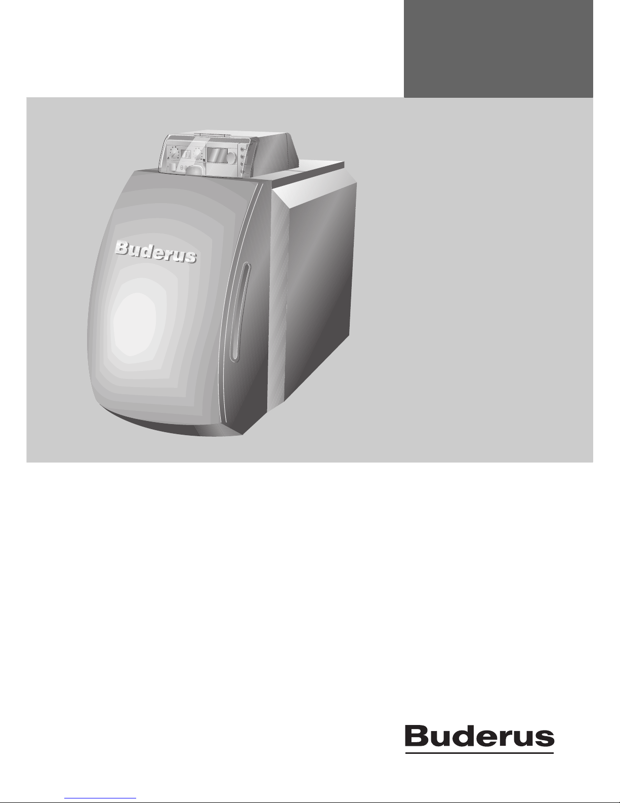
Page 1
For contractors
Please read carefully before
use.
Installation and service
instructions
Fan-assisted
low temperature/
condensing boiler
6 720 615 876-00.1RS
Logano G225/Logano plus
GB225 with BE burner
6 720 616 282 - 02/2008 EN
Page 2
Contents
Logano G225/Logano plus GB225 - We reserve the right to make any changes due to technical modifications.
2
Contents
1 General safety instructions and
explanation of symbols 4
1.1 Safety instructions 4
1.2 Explanation of symbols 5
2 Product details 6
2.1 EU Declaration of Conformity 6
2.2 Intended use 6
2.3 Standards, regulations and directives 6
2.4 Notes on installation and operation 6
2.5 Heating system water quality 6
2.6 Tools, materials and equipment 6
2.7 Disposal 7
2.8 Product description 8
2.9 Contents 9
2.10 Dimensions and specifications 10
2.10.1 Logano G225 BE dimensions 10
2.10.2 Boiler room and ambient conditions 11
2.10.3 Conditions for combustion air supply 12
2.10.4 Conditions for fuel 12
2.10.5 Conditions for the power supply 13
2.10.6 Conditions for the system configuration and
water quality 13
3 Transporting the boiler 14
4 Boiler positioning 15
5 Boiler block assembly 16
5.1 Assembly when delivered in sections 16
5.1.1 Preparation of boiler sections 16
5.1.2 Driving nipples home 17
5.1.3 Preparing the centre section 18
5.1.4 Inserting the packing cord 18
5.1.5 Knocking the centre section into place 19
5.1.6 Boiler section alignment 19
5.1.7 Joining the boiler sections at the upper
and lower boiler hubs with nipples 20
5.1.8 Fitting the anchor rods 22
5.1.9 Installation of the feed pipe and connection
profile 23
5.1.10 Fitting the temperature sensor 25
5.1.11 Fitting the flue outlet 26
5.1.12 Closing the boiler hubs 26
5.2 Checking for leaks 27
5.2.1 Preparing for a leak test 27
5.2.2 Carrying out the leak test 27
5.3 Installation of pre-assembled boiler heat
exchanger 28
5.4 Assembly steps for boilers supplied in
sections and as ready assembled block 28
5.4.1 Fitting the adjustable feet 28
5.4.2 Inserting the hot gas baffle plates 28
5.4.3 Installing the burner door 29
5.4.4 Installing the boiler casing 30
5.5 Positioning and levelling the boiler 37
6 Installing the boiler 38
6.1 Installing the flue pipe 38
6.1.1 Flue pipe sealing collar for negative pressure
flue (pressure at boiler outlet < 0 mbar) 38
6.1.2 Flue pipe sealing collar for positive pressure
flue (pressure at boiler outlet > 0 mbar) 39
6.2 Fitting the water connections 39
6.2.1 Connecting the central heating flow
and return 39
6.2.2 Connecting the safety flow and return 40
6.2.3 Connecting the DHW cylinder 40
6.2.4 Fitting the boiler fill & drain valve
(not supplied) 40
6.3 Filling the heating system and checking
for leaks 41
6.4 Connecting the fuel supply 42
6.5 Electricity connection 42
6.5.1 Fitting the control unit 42
6.5.2 Connecting the mains power supply and other
components 43
6.5.3 Fitting a strain relief 43
6.6 Installing casing parts 44
7 Commissioning the heating system 45
7.1 Bringing the system up to operating pressure 45
7.2 Preparing the heating system for operation 46
7.3 Switching on the heating system 46
7.4 Starting the burner 46
7.5 Raising the flue gas temperature 47
7.5.1 Removing hot gas baffle plates 47
7.5.2 Removing the hot gas check plate 47
7.6 Installing the burner hood 48
7.7 Setting the room controller/control unit 48
7.8 Commissioning report 49
8 Shutting down the heating system 50
8.1 Normal shutdown 50
8.2 Shutting down the heating system
in emergencies 50
8.2.1 What to do in an emergency 50
9 Heating system servicing 51
9.1 Why is regular servicing important? 51
9.2 Preparing the boiler for servicing 51
Page 3

Contents
Logano G225/Logano plus GB225 - We reserve the right to make any changes due to technical modifications.
3
9.3 Cleaning the boiler 52
9.3.1 Cleaning the boiler with cleaning brushes 52
9.3.2 Wet cleaning (chemical cleaning) 53
9.4 Checking the heating system operating
pressure 54
9.5 Servicing and maintenance reports 55
10 Troubleshooting 58
Index 59
Page 4

1
General safety instructions and explanation of symbols
Logano G225/Logano plus GB225 - We reserve the right to make any changes due to technical modifications.
4
1 General safety instructions and explanation of symbols
1.1 Safety instructions
If you smell flue gas
V Switch off the heating system (Æ page 50).
V Open windows and doors.
V Inform an authorised contractor.
Risk of poisoning. An insufficient supply of air can
result in dangerous escape of flue gas.
V Ensure that air inlet or outlet vents are not closed off or
their size is reduced.
V Ensure that no mechanical air extraction equipment
draws combustion air from the boiler room, e.g. cooker
extractor hoods, tumble dryers, ventilation equipment.
V Only operate the boiler with chimneys that provide the
required draught during operation.
V The boiler must not be operated until any deficiency
has been rectified.
V Inform the system operator in writing of the problem
and associated danger.
Danger from escaping flue gases
V Ensure that the flue pipes and seals are not damaged.
V Use silicon as sealing compound.
Dangers posed by explosive and easily
combustible materials
V Never use or store combustible materials (paper, lace
curtains, clothing, thinners, paints, etc.) in the vicinity of
the boiler.
Combustion air
V Keep the combustion air free of corrosive substances
(e.g. halogenated hydrocarbons that contain chlorine
or fluorine compounds). In that way you will prevent
corrosion.
Risk of electric shock when the boiler is open
V Before opening the boiler:
Disconnect the heating system from the power supply
by means of the emergency stop switch or the relevant
circuit breaker in the main fuse board.
V It is not sufficient just to switch off the control unit.
V Safeguard the heating system to prevent unintentional
re-connection.
Danger due to short-circuits
To prevent short circuits:
V Only use genuine Buderus wiring.
Installation and conversion
V Correct and proper installation and adjustment of the
burner and the control unit are the fundamental
requirements for safe and economical operation of the
boiler.
V The boiler may only be installed or converted by an
approved heating contractor.
V Never modify any parts that carry flue gas.
V Only qualified electricians are permitted to carry out
electrical work. Installation regulations must be
complied with.
V With open flue appliances: do not cover or reduce
the size of air vents in doors, windows or walls. If
draught-proof windows are fitted, ensure there is an
adequate supply of combustion air to the room.
V The DHW cylinder may only be used for storing
domestic hot water.
Inspection/maintenance
Heating systems must be regularly maintained.
In that way, you will obtain a high level of efficiency and
low fuel consumption.
You will achieve a high level of operational safety and
reliability.
And you will obtain the cleanest possible combustion.
V Recommendation for users: take out a maintenance
and service contract with an approved heating
contractor covering annual servicing and demanddependent maintenance.
V Servicing and repairs may only be carried out by a
approved heating contractor.
V Have any faults immediately rectified to prevent
damage to the system.
V The operator is responsible for the general and
environmental safety of the heating system.
V Use only genuine spare parts. Damage caused by the
use of parts not supplied by Buderus is not covered by
the Buderus warranty.
Instructing the customer
V Explain to the customer how the boiler works and how
to operate it.
V Inform the customer not to carry out any alterations or
repairs.
Page 5
1
General safety instructions and explanation of symbols
Logano G225/Logano plus GB225 - We reserve the right to make any changes due to technical modifications.
5
1.2 Explanation of symbols
The terms indicate the seriousness of the ensuing risk if
measures for minimising losses are not taken.
– Caution means that minor material losses may occur.
– Warning means that minor injury or severe material
losses may occur.
– Danger means that severe injury may occur. Very
serious cases may result in death.
Notes contain important information for situations in
which there is no risk to the user or the appliance.
Cross-references to particular places in the document or
to other documents are marked with an arrow Æ.
Warnings are indicated by a warning
triangle and a grey background.
Notes are identified in the text by this
symbol. They are bounded by horizontal lines
above and below the text.
Page 6
2
Product details
Logano G225/Logano plus GB225 - We reserve the right to make any changes due to technical modifications.
6
2 Product details
These installation and servicing instructions contain
important information regarding the safe and proper
installation, commissioning and servicing of the boiler.
Product designation:
Logano G225 = fan-assisted, low temperature boiler
Logano plus GB225 = fan-assisted, low temperature
condensing boiler (complete system consisting of Logano
G225 with fitted oil condensing heat exchanger)
The Logano G225 fan-assisted, low temperature boiler
and the Logano plus GB225 fan-assisted, low
temperature condensing boiler are generally referred to in
the remainder of this document simply as the boiler.
These installation and servicing instructions are intended
for qualified heating contractors, who – as a result of their
technical training and experience – are skilled in dealing
with heating systems and oil installations.
2.1 EU Declaration of Conformity
The design and operation of this product conforms to
European Directives and the supplementary national
requirements. Its conformity is demonstrated by the
CE designation. You can view the Declaration of
Conformity on the Internet at www.buderus.de/konfo
or request a copy from your local Buderus office.
2.2 Intended use
The boiler is designed for heating central heating system
water and indirect heating of domestic hot water (e.g. in a
DHW cylinder) in detached houses or apartment
buildings.
Please note the details on the rating plate and the
specifications (Æ Chapter 2.10, page 10) to ensure the
correct use of this appliance.
2.3 Standards, regulations and
directives
2.4 Notes on installation and operation
When installing and operating the heating system
observe the following:
– Local building regulations regarding the installation
conditions
– Local building regulations regarding air supply and
venting systems and the chimney flue connection
– Regulations governing electrical connection to the
mains power supply
– Regulations and standards relating to the safety
systems for the central heating system
– Remember that regional approvals may be required for
the flue system and connecting the condensate outlet
to the public sewer system.
2.5 Heating system water quality
As pure water cannot be used for heat transfer, water
quality is important. Poor water quality can damage
heating systems due to scale formation and corrosion.
2.6 Tools, materials and equipment
For the installation and maintenance of the boiler, you will
need the standard tools used for central heating, gas and
water systems plus set of a metric open-ended spanners
and Allen keys.
The following may also prove useful:
– Sack truck with securing strap or Buderus boiler trolley
–Timber supports
– Cleaning brushes and/or chemical cleaning agent for
wet cleaning
The operations to be carried out for assembly
and installation are identical for the Logano
G225 and the Logano plus GB225 and are
described in these instructions for the
Logano G225.
The differing dimensions, technical
specifications and wall clearances, and the
additional operations for commissioning,
maintenance and servicing of the Logano
plus GB225 can be found in the enclosed
supplement.
Observe all standards and guidelines
applicable to the installation and operation of
this heating system in the country in which it
is used.
Caution: Risk of system damage due to
unsuitable heating system water.
V If oxygen-permeable pipes are used, e.g.
for underfloor heating systems, the
systems must be separated from one
another by heat exchangers. Unsuitable
heating system water promotes sludge
and corrosion formation. That may result in
heat exchanger malfunction and damage.
Page 7

2
Product details
Logano G225/Logano plus GB225 - We reserve the right to make any changes due to technical modifications.
7
If the boiler is delivered in sections, you will also require
the following:
– Size 1.2 compression tool (compression tool docu-
mentation)
– Flat board
– White spirit
– Installation kit (accessory)
– Steel hammer and wooden or rubber mallet
– Half-round bastard file
– Screwdriver (Philips and flat head)
– Flat chisel
– Spanners, sizes 13 mm, 19 mm, 24 mm and 36 mm,
and socket size 19 mm
– Support wedge, flat iron
– Cleaning rags and cloth
– Fine emery cloth
– Wire brush
– Lubricating oil
– Spirit level, ruler, chalk, straight edge
– Blanking flange with vent facility (for pressure test)
2.7 Disposal
V Dispose of boiler packaging in an environmentally
responsible manner.
V All heating system components that have to be
replaced should be disposed of in an environmentally
responsible manner at an authorised disposal site.
Page 8
2
Product details
Logano G225/Logano plus GB225 - We reserve the right to make any changes due to technical modifications.
8
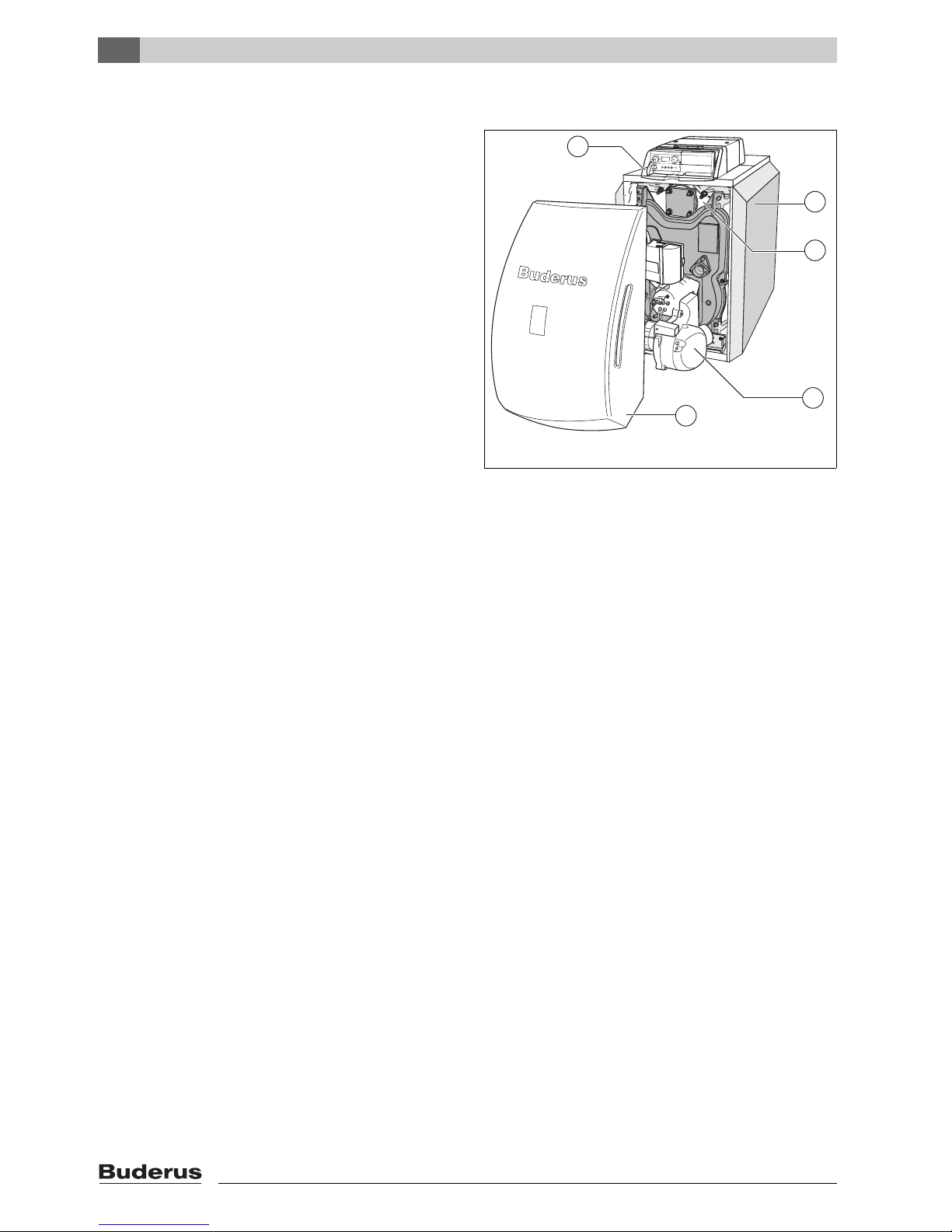
2.8 Product description
The G225 boiler is a fan-assisted, low temperature boiler
and the GB225 boiler is fan-assisted, low temperature
condensing boiler; both of them feature modulating
control of boiler-water temperature.
The boiler comprises:
– Control unit [1]
– Boiler casing [2]
– Boiler heat exchanger and insulation [3]
– Burner [4]
– Heat exchanger system (GB225 only)
The control unit [1] monitors and regulates all electrical
boiler components.
The boiler outer casing [2] prevents heat loss and acts as
a noise insulator.
The boiler heat exchanger [3] transfers the heat
generated by the burner to the heating water.
The insulation [3] prevents radiation losses.
Fig. 1 G225/GB225 boiler
1 Control unit
2 Boiler casing
3 Boiler heat exchanger and insulation
4 Burner
5 Burner hood
6 720 615 876-01.1RS
1
2
3
4
5
Page 9
2
Product details
Logano G225/Logano plus GB225 - We reserve the right to make any changes due to technical modifications.
9
2.9 Contents
V Upon delivery, check that the packaging is
undamaged.
V Check that all components have been delivered.
Boiler as assembled block
Boiler supplied in sections
Component
Quantity
Packaging
Boiler block 1 1 pallet
Boiler casing 1 1 box
Thermal insulation 1 1 shrink-
wrapped pack
Burner, burner hood,
burner door and fixings
1)
,
technical documentation
for burner and boiler.
1) The adjustable feet are packed with the burner hood
11 box
Control unit, technical
documentation for
controller
11 box
Tab. 1 Contents
Component
Quantity
Packaging
Front and rear boiler sections
11 pallet
Centre sections loose
Furniture 1 1 box
Boiler casing 1 1 box
Thermal insulation 1 1 shrink-
wrapped pack
Burner, burner hood,
burner door and fixings
1)
,
technical documentation
for burner and boiler.
1) The adjustable feet are packed with the burner hood
11 box
Control unit, technical
documentation for
controller
11 box
Tab. 2 Contents
Page 10

2
Product details
Logano G225/Logano plus GB225 - We reserve the right to make any changes due to technical modifications.
10
2.10 Dimensions and specifications
2.10.1 Logano G225 BE dimensions
Fig. 2 Connections and dimensions (sizes in mm)
Connections (for sizes see tables below):
VK = Boiler flow
RK = Boiler return
EL = Boiler drain (connection for drain tap)
VS = DHW cylinder flow
RS = DHW cylinder return
VSL = Pressure relief flow pipe (connection for automatic air
vent valve provided by installer)
Connections and sizes:
6 720 615 876-02.1RS
Boiler size 45 55 68
Oil burner Type BE2.3-45 BE2.3-55 BE2.3-68
Boiler sections Number 456
Rated output KW 45 55 68
1)
1) 65 kW (for Spain)
Combustion output KW 48.1 59.0 73.0
2)
2) 69.8 kW (for Spain)
Boiler water content l Approx. 61 Approx. 73 Approx. 85
Gas content l 68.8 85.1 101.4
Flue gas temperature
3)
3) Flue gas temperature to EN 303.
°C 165 180 180
Flue gas mass flow rate kg/s 0.0197 0.0242 0.0299
4)
4) 0.0287 kg/s (for Spain)
CO2 content, oil % 13.5
Available draught Pa 50 50 30
Flue gas back pressure mbar 0.35 0.20 0.35
Permissible flow temperature
5)
5)Safety limit (high limit safety cut-out, STB)
Maximum possible flow temperature = Safety limit (STB) - 10 K
Example: Safety limit (STB) = 100 °C, maximum possible flow temperature = 100 - 10 = 90 °C
The safety limit must meet the national regulations of the country concerned.
°C 100
Permissible operating pressure bar 4
Maximum time constant of temperature control s ≤ 1
Maximum time constant of temperature
monitor and high limit safety cut-out (STB)
s ≤ 1.2
Power supply rating 230 VAC, 50 Hz, 10 A IP 40
Tab. 3 Specifications
Page 11
2
Product details
Logano G225/Logano plus GB225 - We reserve the right to make any changes due to technical modifications.
11
2.10.2 Boiler room and ambient conditions
Boiler size 45 55 68
Boiler overall length (L) mm 1102 1222 1342
Boiler heat exchanger length (LK) mm 626 746 866
Boiler section handling clearance
(width/height/depth)
mm 460/820/150
Boiler heat exchanger handling clearance
(width/height/depth)
mm 460/820/L
K
Combustion chamber length mm 548 668 788
Combustion chamber diameter mm 337
Burner door depth mm 95
Distance between boiler feet (FL) mm 455 575 695
Net weight
1)
kg 246 291 336
Tab. 4 Dimensions, weight and other details
1) Weight inc. packaging approx. 6 – 8 % greater.
Operating conditions Notes - detailed requirements
Temperature in the installation
room
+5 to +40 °C
Relative air humidity max. 90 % No condensation or dripping damp inside the boiler room
Dust/airborne seed − When the boiler is in operation, it is essential to prevent excessive dust levels in
the boiler room, e.g.
– building dust through very dusty building work
The supply of combustion air must not contain excessive amounts of dust or
airborne seed; if necessary, entry should be prevented by means of air filters,
e.g.:
– Air supply loaded with dust from dirt roads and paths.
– Air supply contaminated with dust from production and processing facilities, e.g.
quarries mines, etc.
– Airborne seed from plants.
Halogenated hydrocarbon
compounds
− The combustion air must be free of halogen-hydrocarbon compounds.
– Identify the source of halogenated hydrocarbon compounds and eliminate their ingress.
Where this is impossible, route combustion air from areas which are not contaminated
by halogenated hydrocarbon compounds.
Observe the following:
– Buderus catalogue - Heating Technology Germany
– Code of Practice K3 in the Buderus catalogue
Fans, which extract air from the
installation room.
− While the burner is in operation, no mechanical air extraction equipment that draws air from
the boiler room must be operated, e.g.:
– cooker hood
–dryer
– ventilation equipment
Small animals − Prevent small animals from entering the boiler room, particularly through the air inlet vents –
by fitting the vents with grilles.
Fire safety − Maintain clearances between the boiler and flammable materials in accordance with local
regulations. A minimum clearance of 40 cm should always be maintained. Never store
flammable materials or liquids in the vicinity of the boiler.
Flooding − If flooding is imminent, disconnect the boiler in good time from its fuel and power supply
before water enters the room. Any general and burner components or control equipment,
which come into contact with water, must be replaced before re-commissioning.
Tab. 5 Installation room and environment
Page 12
2
Product details
Logano G225/Logano plus GB225 - We reserve the right to make any changes due to technical modifications.
12
2.10.3 Conditions for combustion air supply
2.10.4 Conditions for fuel
Country-specific fuels
Operating conditions
Boiler output (in case of
multi-boiler systems = total output)
Air intake flow cross-sectional area in cm
2
(clear area)
Air intake flow cross-sectional
area for combustion air drawn
from outside (divided between
max. two apertures)
<50 kW min. 150cm
2
> 50 kW min. 150 cm2 plus 2 cm2 for each kW
in excess of 50 kW
Tab. 6 Combustion air supply – observe national regulations for boilers which draw their air supply from the boiler
room.
Operating conditions Notes – detailed requirements
Permissible fuels for boilers
with Logatop oil burner
– Boilers with a built-in oil burner may only be run on domestic fuel oil (DIN 51603). The
kinematic viscosity of the oil must not exceed 6 mm
2
/s (at 20 °C). That is equivalent to a
Redwood I viscosity of 41.0 s (UK) or Sayboldt viscosity of 45.5 s (USA). If oil of poorer
quality is used, the service/cleaning intervals should be reduced accordingly.
Contamination – Technically free of contamination (e.g. dust, moisture, fluids), i.e. continuous operation will
not result in any accumulations likely to restrict the flow through valves or filters.
Tab. 7 Fuels and remarks
Country Germany
Fuels Domestic fuel oil type EL to DIN 51 603
Remarks The boiler may only be operated with the specified fuel.
Country Austria
Fuels EL fuel oil
Remarks The boiler may only be operated with the fuel specified.
The requirements as per Art. 15 a B-VG regarding emissions and efficiency are satisfied.
Country Switzerland
Fuels EL fuel oil
Remarks The boiler may only be operated with the fuel specified.
The output figures shown in the table "Specifications" are rated output figures.
In some cases, the actual figures attained in practice will be below those stated to comply with LRV
requirements within the specified output range.
Tab. 8 Country-specific fuels and remarks
Page 13
2
Product details
Logano G225/Logano plus GB225 - We reserve the right to make any changes due to technical modifications.
13
2.10.5 Conditions for the power supply
2.10.6 Conditions for the system configuration and water quality
Operating conditions Notes – detailed requirements
Supply voltage 195 – 253 V The outer casing/boiler must be earthed for safety reasons and to function correctly.
Fuse 10 A
Frequency 47.5 – 52.5 Hz Sine wave
Enclosure rating − IP40 (protected against penetration by foreign bodies > 1 mm dia., not protected against
water ingress)
Tab. 9 Mains power supply
Operating conditions Notes – detailed requirements
Operating pressure (above
atmospheric)
0.5 – 4.0 bar
Permissible testing pressure 1.0 – 5.2 bar
Protection against excess
temperatures via TR thermostat
50–90°C
Protection against excess
temperatures via STB high limit
safety cut-out
100 °C
Water quality − The heating system may only be filled and topped up with water of domestic water quality.
We recommend a pH value of 8.2 – 9.5.
Tab. 10 System configuration and water quality
Page 14
3
Transporting the boiler
Logano G225/Logano plus GB225 - We reserve the right to make any changes due to technical modifications.
14
3 Transporting the boiler
This chapter details how you safely transport your boiler.
Caution: Risk of system damage from
impact shocks.
Fragile components could be damaged.
V Observe the transport instructions on the
packaging.
Protect boiler connections from damage and
dirt if the boiler is not to be installed
immediately.
Dispose of packaging in an environmentally
responsible manner.
Warning: Risk of injury if load is
inadequately secured during transportation.
V Use suitable means of transportation, e.g.
the Buderus boiler hand truck with strap.
V Secure the load against falling.
Page 15
4
Boiler positioning
Logano G225/Logano plus GB225 - We reserve the right to make any changes due to technical modifications.
15
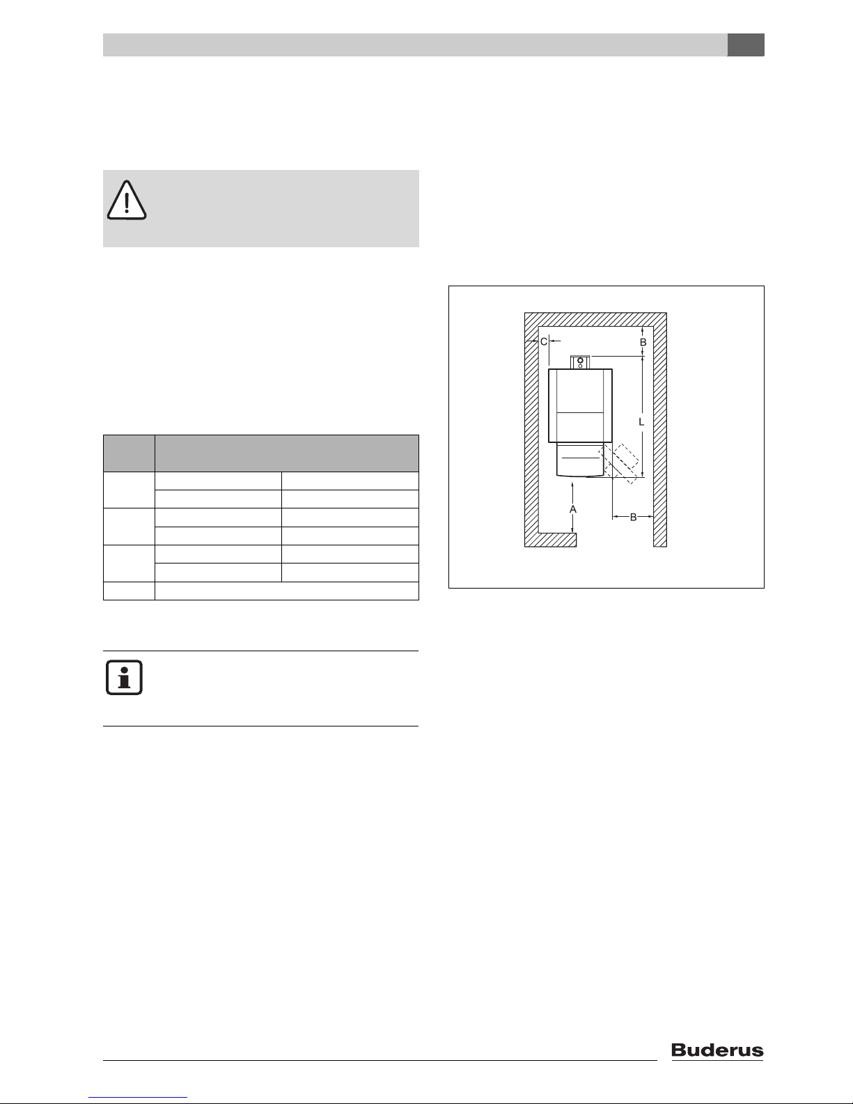
4 Boiler positioning
This section explains how to erect and position the boiler
in the boiler room.
Wall clearances
Wherever possible, position the boiler with the
recommended wall clearances. Reducing the clearances
to the minimum makes the boiler more difficult to access.
The boiler base or foundation must be perfectly flat and
level.
At the factory, the burner door hinges are fitted on the
right hand side. The burner door can be reversed so as to
hinge on the left.
Fig. 3 Boiler room clearances (boiler positioned on the
left-hand or right-hand side)
Caution: Risk of system damage due to
frost!
V Set up the heating system in a room safe
from the risk of frost.
Dimension
Wall clearance
A Recommended 1300
minimum 1000
B Recommended 700
minimum 400
C Recommended 400
minimum 100
L Æ Chapter 2.10.1, page 10
Tab. 11 Recommended and minimum wall clearances
(dimensions in mm)
6 720 615 876-03.1RS
Where applicable, allow extra wall
clearances for additional components such
as DHW cylinder, pipe connections, flue
silencer or other flue components, etc.
Page 16
5
Boiler block assembly
Logano G225/Logano plus GB225 - We reserve the right to make any changes due to technical modifications.
16
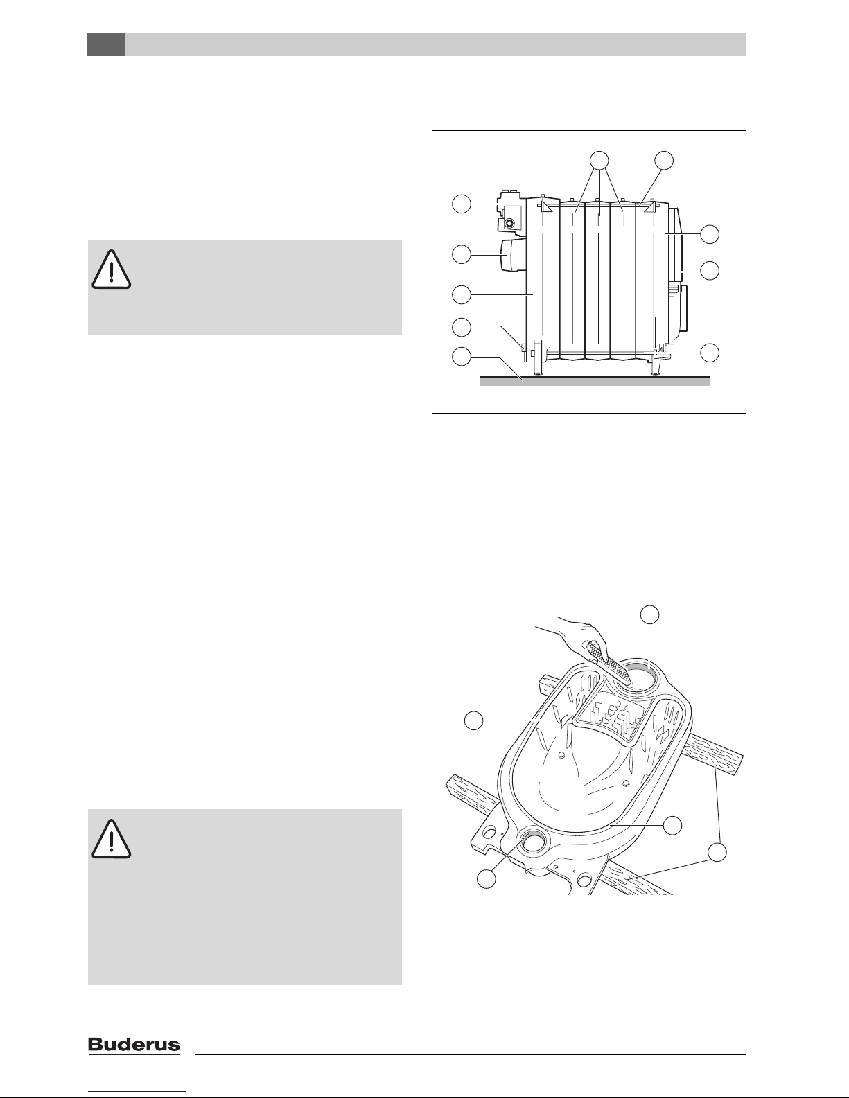
5 Boiler block assembly
The on-site installation is carried out using individual
sections if, because of physical limitations, a boiler block
cannot be handled as a complete unit.
For details of assembling the remainder of the boiler if the
heat exchanger is delivered pre-assembled,
Æ Chapter 5.4, page 28.
Fig. 4 Fully assembled boiler heat exchanger
1 Foundation/installation location
2 Drain
3 Rear section
4 Flue outlet
5 Connecting block
6 Centre sections
7 Anchor rods
8 Front section
9 Burner door
5.1 Assembly when delivered in
sections
V Assemble all boiler sections in accordance with the
following instructions and illustrations.
5.1.1 Preparation of boiler sections
V Lay rear section [2] across two wooden battens [3].
V Clean the boiler bosses [1] with emery paper and a rag.
V Remove any burrs which might have been created with
a file.
V Clean the joint lip/groove [4] using a wire brush and
rag.
Fig. 5 Filing off flash
1 Boiler bosses
2 Rear section
3 Wooden battens
4 Joint lip
Warning: Risk of injury if load is
inadequately secured during transportation.
V Use suitable means of transportation, e.g.
the Buderus boiler hand truck with strap.
V Secure the load against falling.
6 720 615 876-04.1RS
1
2
3
4
5
6
7
8
7
9
Warning: Health risk and risk of injury from
release of vapours and easily combustible
cleaning agents.
V Ensure adequate ventilation inside the
boiler room when using red lead putty,
adhesives and cleaning agents.
V When using a cleaning agent, avoid naked
flames, glowing embers and sparks.
V Observe the manufacturer's handling and
safety instructions.
6 720 615 876-05.1RS
3
4
1
1
2
Page 17

5
Boiler block assembly
Logano G225/Logano plus GB225 - We reserve the right to make any changes due to technical modifications.
17
V Clean the sealing faces of the boiler bosses [1] with a
cloth soaked in white spirit.
V Evenly coat the boiler boss sealing faces with red lead
putty.
V Coat the joint lip/groove [2] with adhesive (primer).
Fig. 6 Coating the boiler hubs with red lead putty
1 Boiler boss sealing face
2 Packing groove
5.1.2 Driving boss liners home
V Clean the boss liners with a cloth soaked in white spirit.
V Evenly coat the boss liners with red lead putty.
V Insert the boss liners straight into the upper and lower
hub of the rear section and hammer home securely with
alternate heavy blows.
V Remove any burrs with a file.
Fig. 7 Driving boss liners home
1 Boss liner in the upper boiler hub
2 Boss liner in the lower boiler hub
2
1
1
6 720 615 876-06.1RS
Leave the two boss liners protruding approx.
30 mm from the boiler boss in each case.
6 720 615 876-07.1RS
2
1
Page 18
5
Boiler block assembly
Logano G225/Logano plus GB225 - We reserve the right to make any changes due to technical modifications.
18
5.1.3 Preparing the centre section
Prepare the centre section in the same way as the rear
section (Æ 5.1.1, page 16).
Fig. 8 Preparing the centre section
1 Boiler boss sealing face
2 Packing grooves
5.1.4 Inserting the packing cord
V Unroll the required length of packing cord from the roll
supplied.
V Peel the backing paper from the packing cord, as you
insert the cord into the packing groove.
V Insert the flexible packing cord into the packing groove,
starting in the upper boiler hub area, and lightly press
in.
V Where the 2 ends meet, overlap the packing cord by
2 cm and press firmly together.
Fig. 9 Inserting the packing cord
6 720 615 876-08.1RS
2
1
1
Caution: Risk of system damage due to
leaking boiler sections.
V To ensure that the joint faces between the
boiler sections are properly sealed, the
packing cord must not be stretched
during fitting.
V Carefully insert the packing cord into the
boiler packing grooves.
6 720 615 876-09.1RS
Page 19

5
Boiler block assembly
Logano G225/Logano plus GB225 - We reserve the right to make any changes due to technical modifications.
19
5.1.5 Knocking the centre section into place
V Turn the centre section around and locate with the
upper and lower boiler hubs on the boss liners of the
rear section.
V Drive the centre section onto the rear section [2] using
a wooden or a rubber mallet [1].
Fig. 10 Knocking the centre section into place
1 Wooden or rubber mallet
2 Rear section
5.1.6 Boiler section alignment
V Right the part assembled block comprising two boiler
sections.
V Position a flat board [1] underneath the centre section
[2] so that the boiler heat exchanger is slightly tilted to
the rear for the subsequent assembly process.
Fig. 11 Righting the part assembled block
1 Flat board
2 Centre section
6 720 615 876-10.1RS
2
1
Warning: Risk of injury due to inadequately
secured boiler sections.
V Secure the partly assembled boiler heat
exchanger against tipping over.
6 720 615 876-11.1RS
2
1
Page 20

5
Boiler block assembly
Logano G225/Logano plus GB225 - We reserve the right to make any changes due to technical modifications.
20
5.1.7 Joining the boiler sections at the upper and
lower boiler bosses with boss liners
Fig. 12 Assembling the pull rods
1 Pull rod threaded connection (incorrectly joined)
2 Pull rod threaded connection (correctly joined)
V Push one pull rod each through the lower and the
upper boiler hub of the part assembled block.
Fig. 13 compression tool fitted to the top boiler boss
1 Compression unit
2 Pressure plate (dia. 135 × 25, top boiler boss)
3 Brace plate (dia. 135 x 25, top boiler boss)
4 Wedge
5 Pull rod in the upper boiler hub
Caution: Risk of boiler damage due to
unsuitable compression tool.
V Use only the size 1.2 compression tool
suitable for your boiler (Æ observe
documentation supplied with
compression tool).
Caution: Risk of damage to compression
tool
The compression tool may be damaged or
destroyed, if you compress pull rods with
loose threaded connections.
V After each compression operation, check
the screwed joints of the pull rods [1, 2]
and tighten if necessary.
The pull rods [2] is correctly assembled
when it is fully fitted together and no
thread is visible.
V Keep the thread of the compression tool
clean. Dirty threads can cause damage to
the compression tool when in use.
6 720 615 876-12.1RS
2
1
Caution: Risk of boiler damage due to
incorrectly positioned pressure plate.
If the pressure plate is seated against the
joint lip/groove of the boiler section during
the compression operation, the joint may be
damaged and subsequently leak.
V Ensure that the pressure plate is seated
flat against the boiler boss.
6 720 615 876-13.1RS
54
3
2
1
Page 21

5
Boiler block assembly
Logano G225/Logano plus GB225 - We reserve the right to make any changes due to technical modifications.
21
V Slide the pressure plates onto the pull rods in the top
and bottom boiler bosses.
V Push the mating flange onto the pull rod of the lower
and upper boiler bosses, and secure with the
respective wedges.
V Thread the compression units onto the pull rod threads.
V Hold the pull rods at the centre of the boiler bosses and
slightly draw together the compression tools using the
compression unit.
Fig. 14 Compression tool assembled at the lower boiler
hub
1 Compression unit
2 Pressure plate (dia. 80 x 25)
3 Brace plate (dia. 80 x 25, bottom boiler boss)
4 Wedge
5 Pull rod in the lower boiler boss
V Place the two ratchet spanners [1] on the clamp nuts
[2] of the compression tools and press the boiler
sections together by evenly tightening the nuts.
V Release and remove the compression tool.
V Hammer the boss liners into the bosses of the partly
assembled boiler heat exchanger (Æ Chapter 5.1.2,
page 17).
V Prepare all other centre sections as described above
and then join using boss liners.
Fig. 15 Locating the ratchet
1 Spanners
2 Clamping nuts
Push the compression units so far onto the
pull rod threads, that two threads protrude
from the compression units.
6 720 615 876-14.1RS
5
4
3
2
1
Caution: Risk of boiler damage due to
leaking boiler sections.
V Ensure that in each compression
operation only one boss/liner joint (one
boss/liner joint consists of two sections) is
being pressed together.
V Never jam boss liners into the boiler
bosses of the boiler section.
V Stop pressing the sections together when
the boiler bosses meet.
6 720 615 876-15.1RS
2
1
Page 22

5
Boiler block assembly
Logano G225/Logano plus GB225 - We reserve the right to make any changes due to technical modifications.
22
Front section assembly
Due to the threaded studs, never use the auxiliary flange
at the front of the upper boiler hub when assembling the
front section.
V Push the pull rod together with the compression unit
through the upper boiler hub.
V Carry out all remaining steps as described above
(Æ Chapter 5.1.7, page 20).
Fig. 16 Fitting the compression tool to the front section
5.1.8 Fitting the anchor rods
V Slot the anchor rods [1] fitted with spring washers [3]
into the cast lugs [4] near the boiler bosses on the right
and left and at the bottom.
V Screw the nuts onto the threads of the anchor rods [1]
by hand.
V Tighten the nuts on the anchor rods 1 to 1½ turns.
V Undo the compression tool [5] and remove.
Fig. 17 Fitting the anchor rods – arrangement of the
dished washers
1 Anchor rods
2 Nut
3 Spring washers
4 Cast lugs
5 Compression tool
6 720 615 876-16.1RS
Insert the anchor rods [1] before removing
the compression tool [5].
Never remove the compression tool first.
Caution: Risk of system damage due to
incorrect fitting of spring washers.
V Ensure that the spring washers [3] are
facing each other on the anchor rods [1].
6 720 615 876-17.1RS
5
4
3
3
2
1
1
Page 23

5
Boiler block assembly
Logano G225/Logano plus GB225 - We reserve the right to make any changes due to technical modifications.
23
5.1.9 Installation of the feed pipe and connection
profile
The feed pipe [3] and connecting block [1] are already
fitted if the boiler heat exchanger is supplied preassembled.
V Secure the feed pipe [3] with gasket in place to the
connecting block using M 8 × 16 screws.
Fig. 18 Installation of the feed pipe to the connecting
block
1 Connecting block
2 Gasket
3 Feed pipe
4 M 8 ×16 screws (brass)
V Remove the nuts from the threaded studs.
V Slide gasket [1] over the feed pipe.
V Slide feeder pipe with connection fitting attached and
gasket [1] in place into the top boiler boss from the
back.
Fig. 19 Installation of the feed pipe and connecting
block
1 Gasket
If there is insufficient space behind the boiler,
insert the feed pipe [3] from the front of the
boiler (not forgetting the gasket for the boiler
boss) before fitting the connection profile [1].
6 720 615 876-18.1RS
4
3 2 1
6 720 615 876-19.1RS
1
Page 24

5
Boiler block assembly
Logano G225/Logano plus GB225 - We reserve the right to make any changes due to technical modifications.
24
V Position the connecting block onto the threaded studs,
and tighten four nuts by hand.
V Evenly tighten the connection profile nuts in a diagonal
sequence using a torque wrench [1]
(torque: max. 60 Nm).
Fig. 20 Assembling the connection profile
1 Torque wrench
You can seal off the connections that are not required
using the blanking plugs [1] supplied. When the boiler is
supplied as ready assembled block, these plugs have
already been fitted.
V Insert blanking plugs [1] fitted with plain washers [2]
into connections that are not required.
Fig. 21 Sealing off connections that are not required
1 Blanking plug
2 Plain washer
6 720 615 876-20.1RS
1
6 720 615 876-21.1RS
2
2
1
1
Page 25

5
Boiler block assembly
Logano G225/Logano plus GB225 - We reserve the right to make any changes due to technical modifications.
25
5.1.10 Fitting the temperature sensor
The temperature sensor is delivered in the pack
containing the burner, burner hood and burner door.
The temperature sensor is fitted to a reducer.
V Fit the reducer with temperature sensor attached.
Fig. 22 Temperature sensor fitted to reducer
Fig. 23 Fitting the temperature sensor
1 Temperature sensor
6 720 615 876-22.1RS
6 720 615 876-23.1RS
1
Page 26

5
Boiler block assembly
Logano G225/Logano plus GB225 - We reserve the right to make any changes due to technical modifications.
26
5.1.11 Fitting the flue outlet
The flue outlet is fitted with a cord gasket.
V Remove the washers and nuts from the threaded studs.
V Position the flue outlet onto both threaded studs on the
rear section and secure with nuts.
Fig. 24 Fitting the flue outlet
5.1.12 Closing the boiler hubs
The reducer supplied is required for fitting the boiler fill &
drain valve (not supplied).
V Fit and seal the reducer into the bottom rear boiler
boss.
V Fit the boiler fill & drain valve to the reducer.
Fig. 25 Fitting and sealing the reducer
1 Reducer (R 1½" to Rp ½")
V On the front boiler section, seal off the top boiler boss
with the blanking plate [1].
V Insert the blanking plug [2] with plain washer in place
into the bottom boiler boss.
Fig. 26 Closing the boiler hubs at the front section
1 Dummy flange
2 Blanking plug
6 720 615 876-24.1RS
6 720 615 876-25.1RS
1
6 720 615 876-26.1RS
2
1
Page 27

5
Boiler block assembly
Logano G225/Logano plus GB225 - We reserve the right to make any changes due to technical modifications.
27
5.2 Checking for leaks
Only carry out a leak test if the boiler heat exchanger has
not been delivered pre-assembled.
5.2.1 Preparing for a leak test
V Seal off all boiler bosses
(Æ Chapter 5.1.12, page 26).
V Seal off the flow and return connections. (Fit a air vent
valve to the Rp ¾ connection profile.)
5.2.2 Carrying out the leak test
Carry out a leak test at a test pressure of 5.8 bar (in
accordance with the requirements of the European
Pressure Vessel Directive).
V Slowly fill the boiler block via the boiler fill & drain valve.
While filling, keep the air vent valve at the highest point
of the boiler open until water runs out of it.
Hub joints leaking?
V If a hub joint is leaking, first drain the water through the
boiler fill & drain valve.
V Remove the water pipes.
V Remove the feed pipe.
V Release and remove the anchor rods.
V Split the leaking boiler heat exchanger at the leaking
joint by driving in wedges or chisels.
For the remaining stages of boiler installation, refer to
Æ Chapter 5.4, page 28.
Fig. 27 Separating the boiler block
Observe the specifications on the rating
plate.
Use a class 1.0 pressure gauge for the
pressure test.
Caution: Risk of system damage from
excessive pressure.
V Ensure that no pressure, control or safety
equipment is fitted while the leakage test
is being carried out.
Clean the bosses before reassembling.
Always fit new boss liners and new packing
cord when reassembling.
Press the boiler heat exchanger back
together.
Fit the anchor rods and feed pipe.
Connect the water pipes.
Repeat the leak test.
6 720 615 876-27.1RS
Page 28

5
Boiler block assembly
Logano G225/Logano plus GB225 - We reserve the right to make any changes due to technical modifications.
28
5.3 Installation of pre-assembled boiler
heat exchanger
Pre-assembled boiler blocks are leak tested in the factory
prior to delivery.
V Cut through the securing straps [1].
V Remove the pallet prior to positioning the boiler block.
Fig. 28 Boiler block on a pallet (as delivered condition)
1 Securing straps
5.4 Assembly steps for boilers supplied in sections and as ready assembled block
Carry out the steps detailed in this chapter for deliveries
in sections or as block. Any assembly discrepancies
between the sectional and block delivery are highlighted
in this text.
5.4.1 Fitting the adjustable feet
You can level the boiler using the adjustable feet (for
packing details see package contents) to prevent air
pockets forming inside the boiler.
V Tip the boiler or support it on a square timber.
V Insert adjustable feet 5 – 10 mm.
V Gently set the boiler down.
Fig. 29 Fitting the adjustable feet
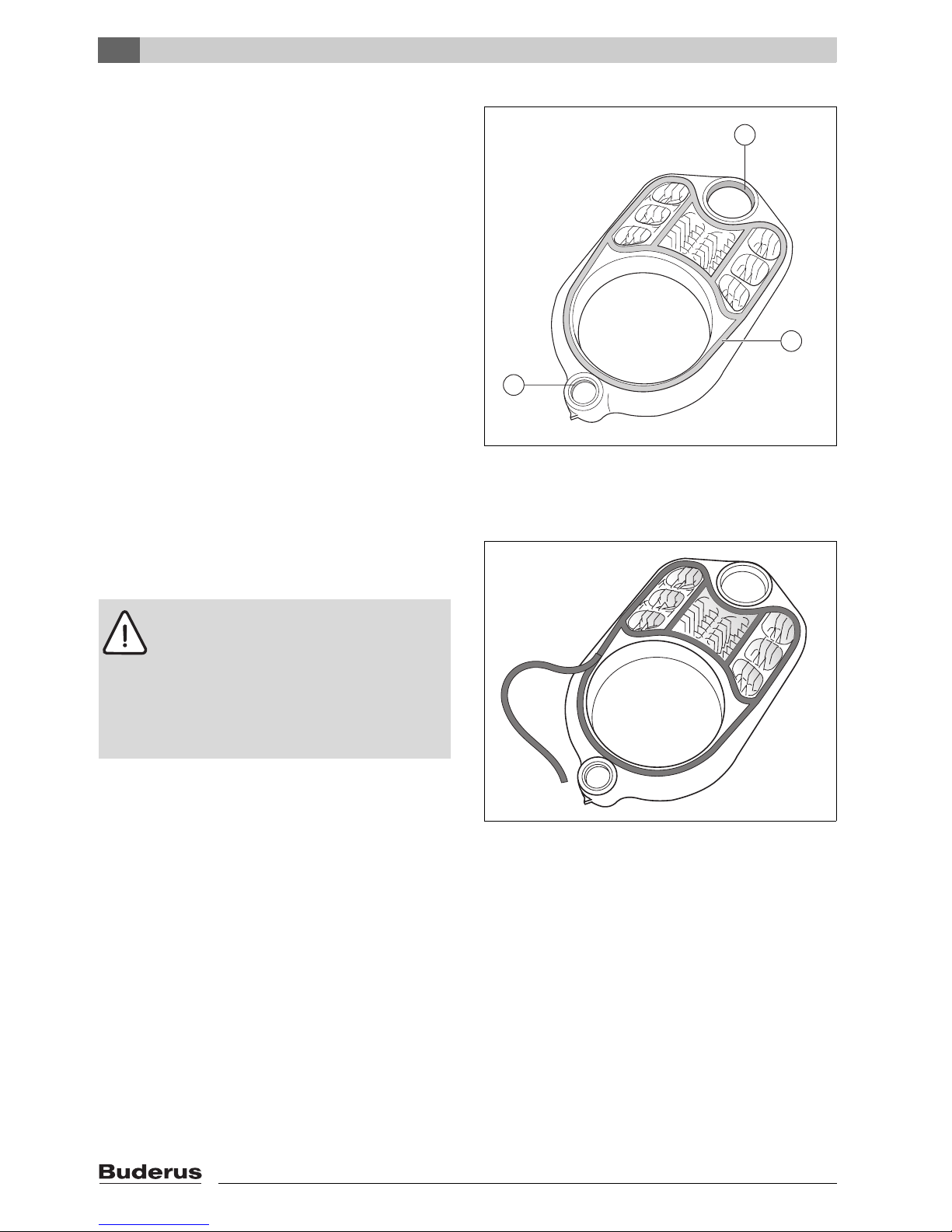
5.4.2 Inserting the hot gas baffle plates
V Remove the corrugated cardboard packaging when
the block is supplied ready assembled.
V If the boiler is supplied in sections, remove the hot gas
baffles from the box containing the loose fittings.
V Insert the hot gas baffles into the centre 2nd hot gas
flues as indicated in the table below. The cast lugs
should point towards the centre of the boiler.
Fig. 30 Inserting hot gas baffles into 2nd hot gas flue
(in this case in the centre)
Danger: Risk of fatal injury from falling
objects.
V Ensure that there is a suitable means of
supporting the load.
V Observe all locally applicable health &
safety regulations regarding lifting
equipment.
6 720 615 876-28.1RS
1
6 720 615 876-29.1RS
6 720 615 876-30.1RS
Page 29

5
Boiler block assembly
Logano G225/Logano plus GB225 - We reserve the right to make any changes due to technical modifications.
29
V Insert the hot gas baffles into the centre 3rd hot gas
flues as indicated in the table below. The cast lugs
should point outwards.
Fig. 31 Inserting hot gas baffles into 3rd hot gas flue
The flue gas temperature can be increased by removing
the hot gas baffles (Æ Chapter 7.5, page 47).
5.4.3 Installing the burner door
You can fit the burner door with the hinges on the right or
left. In the following points, assembly on the right hand
side is described.
V Secure the two hinge pins to the front boiler section
with one M 12 × 35 hexagon bolt [1] in each case.
Fig. 32 Fitting the hinge pins (on the right in this exam-
ple)
1 M 12 × 35 hexagon bolt
V Fit the twin-slooted hinge lobe brackets to the burner
door with an M 12 x 25 bolt in each case.
V Hook the burner door with the hinge lobes onto the
hinge pins.
V Close the boiler door.
Fig. 33 Hanging the burner door (on the right in this
case)
1 M 12 × 25 hexagon bolt
Boiler size incl. oil burner 45 55 68
2nd hot gas flue Top - - -
central - 2 -
bottom - 2 -
3rd hot gas flue 2 - -
Tab. 12 Hot gas baffle plate arrangement
6 720 615 876-31.1RS
6 720 615 876-32.1RS
1
1
Caution: Risk of system damage due to
leaking burner door.
V Tighten the hexagon bolts on the burner
door evenly.
6 720 615 876-33.1RS
Page 30

5
Boiler block assembly
Logano G225/Logano plus GB225 - We reserve the right to make any changes due to technical modifications.
30
5.4.4 Installing the boiler casing
Fitting the boiler rear panel
V Insert the spacer pins into the rear section.
Fig. 34 Fitting the spacer bolts
V Secure the boiler back panel with nuts to the threaded
and spacer pins.
Fig. 35 Fitting the boiler rear panel
Installation of the upper tie bar
V Secure the top crossmember to threads of the anchor
rods [1] using the nuts supplied.
Fig. 36 Installation of the upper tie bar
1 Anchor rods
6 720 615 876-34.1RS
6 720 615 876-35.1RS
6 720 615 876-36.1RS
1
Page 31

5
Boiler block assembly
Logano G225/Logano plus GB225 - We reserve the right to make any changes due to technical modifications.
31
Installation of the lower tie bar
V Secure the lower tie bar with hexagon bolts to the front
section.
Fig. 37 Installation of the lower tie bar
Installation of the thermal insulation
V Position the thermal insulation over the boiler block.
V Push the thermal insulation below the boiler block, in
the direction of the arrow.
V Position the tabs of the thermal insulation [2] in front of
the top crossmember and pull them together with a
spring clip [1].
Fig. 38 Installation of the thermal insulation
1 Spring strap
2 Thermal insulation tabs
6 720 615 876-37.1RS
6 720 615 876-38.1RS
2
1
Page 32

5
Boiler block assembly
Logano G225/Logano plus GB225 - We reserve the right to make any changes due to technical modifications.
32
Fitting the temperature sensor and communication
cable
V Press the cable grip [1] into the holes provided in the
bottom crossmember.
V Lay the cables over the thermal insulation.
V Insert the cables into the strain relief. The clear length
must be 70 to 75 cm.
V Secure the cables via the strain relief using two self-
tapping screws.
The cables must always be laid as shown, regardless of
whether the door opens to the right or to the left.
Fig. 39 Fitting the temperature sensor and communica-
tion cable
1 Strain relief
2 Temperature sensor and communication cable
A Push the strain relief into the holes of the lower tie bar
B Insert and secure the cables
Fitting the mains power cable
V Fit the cable clip [1].
V Insert mains supply cable into the cable clip [1].
The mains power cable must always be laid as shown,
regardless of whether the door opens to the right or to the
left.
Connecting cables to the SAFe
V Connect temperature sensor [2], communication [3]
and mains power cables to the SAFe [4] as shown in
the wiring diagram (Æ burner documentation).
Fig. 40 Fitting the mains power cable
1 Cable clip for mains power cable
2 Temperature sensor lead
3 Communication cable
4 SAFe
6 720 615 876-39.1RS
A
B
2
1
6 720 615 876-40.1RS
4
3
21
Page 33

5
Boiler block assembly
Logano G225/Logano plus GB225 - We reserve the right to make any changes due to technical modifications.
33
Fitting the side panels
The side panel installation for the left-hand and right-hand
side is identical (in this example on the right-hand side
panel).
V Push the snap nut onto the angled sheet steel of the
side panel, until it locks into the hole provided.
Fig. 41 Fitting the snap-on nut (in this example on the
right-hand side panel)
V Slot the side panel into the end flange of the bottom
crossmember [1].
Fig. 42 Pushing the front lower side panel into place
1 Angled part of the lower tie bar
V Slightly lift the side panel.
V Hook the top cutout in the side panel over the top
crossmember [A].
V Hook the rear part of the side panel over the protruding
hook [B].
Fig. 43 Hooking-in the side panel
A Top crossmember
B Protruding hook
6 720 615 876-41.1RS
1
A
B
6 720 615 876-43.1RS
Page 34

5
Boiler block assembly
Logano G225/Logano plus GB225 - We reserve the right to make any changes due to technical modifications.
34
V Push the side panel in at the bottom and fix to the rear
panel with the snap-lock catch [1].
Fig. 44 Securing the side panel to the rear panel
1 Snap-lock catch
V Fit brackets [1] for fixing the burner hood to left and
right side panels.
Fig. 45 Fitting brackets to side panels
1 Bracket
6 720 615 876-44.1RS
1
1
6 720 615 876-45.1RS
Page 35

5
Boiler block assembly
Logano G225/Logano plus GB225 - We reserve the right to make any changes due to technical modifications.
35
Fitting the front boiler cover
V Hook the front boiler cover with its cutout into the top
crossmember and push back.
V Secure the front boiler cover with two self-tapping
screws to the side panels.
Fig. 46 Fitting the front boiler cover
Fitting the temperature sensor
(pre-assembled boiler only)
If the boiler is delivered pre-assembled, the temperature
sensor must now be fitted.
The temperature sensor [1] is packed in the pack
containing the burner, burner hood and burner door.
The temperature sensor [1] is fitted to a reducer.
V Fit the reducer with temperature sensor [1] attached.
Fig. 47 Fitting the temperature sensor
1 Temperature sensor
For details of fitting the rear boiler top panel,
Æ Chapter 6.6, page 44.
6 720 615 876-46.1RS
6 720 615 876-47.1RS
1
Page 36

5
Boiler block assembly
Logano G225/Logano plus GB225 - We reserve the right to make any changes due to technical modifications.
36
Installing the cable entry
V Secure the cable entry to the boiler back panel hole.
V Slide rubber hood [1] over the temperature sensor and
connect temperature sensor lead.
Fig. 48 Installing the cable entry
1 Rubber sleeve
Insulating the connecting block
V Cut out the insulating shells of the connecting block at
the indicated and required positions.
Fig. 49 Cutting out the insulating shells
V Slide the two halves of the insulation box onto the
connection profile.
Fig. 50 Insulating the connection profile.
6 720 615 876-48.1RS
1
6 720 615 876-49.1RS
6 720 615 876-50.1RS
Page 37

5
Boiler block assembly
Logano G225/Logano plus GB225 - We reserve the right to make any changes due to technical modifications.
37
V Push the heat shield onto the insulating shells.
Fig. 51 Installation of the heat shield
5.5 Positioning and levelling the boiler
V Move the boiler into its final location.
V Level the boiler by inserting the adjustable feet uo or
down as required and using a spirit level.
Fig. 52 Levelling the boiler horizontally
6 720 615 876-51.1RS
Protect boiler connections from damage and
dirt if the boiler is not to be installed
immediately.
7 747 019 141-11.1RS
Page 38

6
Installing the boiler
Logano G225/Logano plus GB225 - We reserve the right to make any changes due to technical modifications.
38
6 Installing the boiler
This chapter details how you install your boiler correctly.
The individual steps involved are:
– Flue connection
– Connecting the water pipes
– Making the electrical connections
For information on connecting the fuel supply, please
consult the burner documentation.
6.1 Installing the flue pipe
V Make the flue gas connection in accordance with the
requirements applicable in your country.
6.1.1 Flue pipe sealing collar for negative pressure flue (pressure at boiler outlet < 0 mbar)
We recommend fitting a flue pipe sealing collar (option) in
order to achieve the best possible seal.
V Slide jubilee clips [4] over the flue pipe [1].
V Push flue pipe [1] fully home onto the boiler flue outlet
[3].
V Wrap flue pipe sealing collar [2] around the flue pipe/
flue outlet joint so that it overlaps the joint.
V Position one jubilee clip [4] on the flue pipe and the
other on the flue outlet.
V Tighten the jubilee clips [4] so that the flue pipe sealing
collar [2] sits snugly and evenly in place.
Fig. 53 Fitting the flue pipe sealing collar (example)
1 Flue pipe
2 Flue pipe sealing collar
3 Boiler flue outlet
4 Jubilee clip
6 720 615 876-53.1RS
1
23
4
Page 39

6
Installing the boiler
Logano G225/Logano plus GB225 - We reserve the right to make any changes due to technical modifications.
39
6.1.2 Flue pipe sealing collar for positive pressure flue (pressure at boiler outlet > 0 mbar)
The overpressure-tight flue pipe sealing collar
(accessories, part no. 535 4404) must be fitted.
V Slide the flue pipe sealing collar [3] and two jubilee
clips [2] over the flue pipe [4].
V Push flue pipe [4] and flue pipe sealing collar [3] onto
the boiler flue outlet [1].
V Tighten jubilee clips [2].
Fig. 54 Making the flue pipe sealing collar
1 Flue outlet
2 Jubilee clip
3 Flue pipe sealing collar
4 Flue pipe
6.2 Fitting the water connections
6.2.1 Connecting the central heating flow and
return
V Connect central heating return to connection RK.
V Connect the central heating flow to connection VK.
Fig. 55 Connecting the central heating flow and return
Key to fig. 55 - 58:
VSL: Flow safety line
VK: Boiler flow
RK: Boiler return
VS: DHW cylinder flow
RS: DHW cylinder return
EL: Drain
6 720 615 876-54.1RS
2 2
4
3
3
1
Caution: Risk of system damage from
leaking connections.
V Fit the connecting pipes to the boiler in
such a way that they are not under stress.
Caution: Risk of system damage due to lack
of water.
The boiler requires a minimum pressure
switch to protect it against lack of water. You
can obtain this as an accessory.
V Observe the installation instructions for
the accessory.
We recommend fitting a dirt filter (option) to
the central heating return to prevent
contamination of the boiler by the water.
6 720 615 876-55.1RS
VK
RK
Page 40

6
Installing the boiler
Logano G225/Logano plus GB225 - We reserve the right to make any changes due to technical modifications.
40
6.2.2 Connecting the safety flow and return
We recommend you fit a boiler safety assembly
(accessory) and an air vent valve (accessory) to
connector VSL.
Fig. 56 Connecting the air vent valve to the safety flow
6.2.3 Connecting the DHW cylinder
V Connect the DHW cylinder return to connection RS.
V Connect the DHW cylinder flow either at VS1 or VS2.
V Seal off the surplus VS and RS connector.
Fig. 57 DHW cylinder connection
6.2.4 Fitting the boiler fill & drain valve (not supplied)
V Fit and seal the boiler fill & drain valve to connection EL.
Fig. 58 Fitting boiler fill & drain valve
Caution: Risk of system damage due to
incorrect components connected to
connection VSL.
V Never connect a solar heating system,
DHW cylinder or other heating circuit to
connection VSL.
VSL
6 720 615 876-56.1RS
RS1
VS1
VS2
RS2
6 720 615 876-57.1RS
EL
6 720 615 876-58.1RS
EL
Page 41

6
Installing the boiler
Logano G225/Logano plus GB225 - We reserve the right to make any changes due to technical modifications.
41
6.3 Filling the heating system and
checking for leaks
Check the heating system for leaks before commissioning
to ensure there are no leaks when the system is in
operation. Pressurise the heating system to 1.3x
permissible operating pressure (observe the response
pressure of the safety valve).
Fig. 59 Pressure gauge for sealed unvented systems
1 Red needle
2 Pressure gauge needle
3 Green range
V Close the pressure expansion vessel against the
system by closing the cap valve.
V Check the connections and pipework for leaks.
V Open the mixing and shut-off valves on the heating
water (primary) side.
V Connect hose to the water tap. Push a hose filled with
water onto the hose ferrule of the boiler fill & drain valve
and open the valve.
V Open the cap of the automatic air vent valve by one full
turn to allow air to escape.
V Slowly fill the heating system. Observe the pressure
gauge (Æ fig. 59) while doing so.
V Close the water tap and the boiler fill & drain valve once
the required operating pressure has been reached.
V Vent the heating system via the radiator bleed valves.
V Top up with water if the pressure drops as a result of
venting the system.
V Remove the hose from the boiler fill & drain valve.
Caution: Risk of system damage from
excess pressure when testing for leaks.
Pressure, control and safety equipment may
be damaged by excessive pressure.
V When you carry out the leakage test,
ensure that no pressure, control or safety
equipment that cannot be isolated from
the boiler water chamber is fitted.
6 720 615 876-59.1RS
3
2
1
Page 42

6
Installing the boiler
Logano G225/Logano plus GB225 - We reserve the right to make any changes due to technical modifications.
42
6.4 Connecting the fuel supply
Make the fuel connection in accordance with all locally
applicable regulations. We recommend the installation of
a fuel filter.
V Visually inspect the fuel pipe and clean or replace, if
necessary.
V Install the shut-off valve into the fuel supply pipe.
V Connect the fuel pipe to the boiler in such a way that it
is not under stress.
V Check the flue pipe for tightness.
V Connect up the fuel supply in accordance with the
locally applicable regulations.
6.5 Electricity connection
6.5.1 Fitting the control unit
V Place the push-in hooks of the control unit into the oval
holes.
V Push the control unit towards the burner door.
V Let the resilient hooks of the control unit click into the
openings by pushing the control unit down.
Fig. 60 Fitting the control unit
Danger: Risk of fatal electric shock.
V Only qualified electricians are permitted to
carry out electrical work. Installation
regulations must be complied with.
V Before opening the boiler:
Disconnect the heating system from the
power supply by means of the emergency
stop switch or the relevant circuit breaker
in the main fuse board.
V Safeguard the heating system to prevent
unintentional re-connection.
V Observe all installation instructions.
6 720 615 876-60.1RS
Page 43

6
Installing the boiler
Logano G225/Logano plus GB225 - We reserve the right to make any changes due to technical modifications.
43
6.5.2 Connecting the mains power supply and
other components
V Undo the two screws on the control unit cover and
remove the cover.
Create a permanent mains power connection in
accordance with local regulations.
V Route all cables through the cable entries to the control
unit and connect in accordance with the wiring
diagram.
Fig. 61 Removing the cover
6.5.3 Fitting a strain relief
Secure all cable runs with cable clamps (standard control
unit delivery):
1. Insert the cable clamp together with the cable from the
top into the slots in the frame.
2. Slide the cable clamp downwards.
3. Press in.
4. Flip the toggle up.
Fig. 62 Securing cables with a cable clamp
Danger: Risk of fire
Hot boiler components may damage cables.
V Ensure that all cables are routed through
the cableways provided or along the
boiler's insulation material.
6 720 615 876-61.1RS
6 720 615 876-62.1RS
Page 44

6
Installing the boiler
Logano G225/Logano plus GB225 - We reserve the right to make any changes due to technical modifications.
44
6.6 Installing casing parts
V Slot the control unit cover [1] into the guides and slide
downwards.
V Secure the controller cover [1] with the two screws.
V Slide the tabs of the rear boiler top panel [3] under the
front boiler top panel [4].
V Lower the rear boiler top panel [3] onto the side panels.
Fig. 63 Fitting hoods
1 Control unit cover
2 Tabs
3 Rear boiler cover
4 Front boiler cover
5 Side panel
V Place rear control unit cover [2] on rear boiler top panel
and fasten with two screws.
Fig. 64 Fitting the end hood
1 Controller cover
2 End hood
6 720 615 876-63.1RS
1
2
2
3
45
6 720 615 876-64.1RS
1
2
Page 45

7
Commissioning the heating system
Logano G225/Logano plus GB225 - We reserve the right to make any changes due to technical modifications.
45
7 Commissioning the heating system
This chapter details the commissioning independent of
the installed control unit.
V Complete the commissioning report during the
commissioning procedure (Æ Chapter 7.8, page 49).
For further information on boiler room conditions and
requirements, combustion air supply and flue systems,
and boiler operation, see Chapter 2.10.1, page 10 to
Chapter 2.10.6, page 13.
7.1 Bringing the system up to operating pressure
Bring the system up to the standard operating pressure
before commissioning.
V Adjust the red pointer [1] of the pressure gauge to the
required operating pressure of at least 1 bar (applies to
sealed unvented systems).
V Replenish the heating water or drain via the boiler fill &
drain valve until the required operating pressure is
obtained (Æ Chapter 6.3, page 41).
V Vent the heating system during filling.
Fig. 65 Pressure gauge for sealed unvented systems
1 Red needle
2 Pressure gauge needle
3 Green range
Warning: Risk of boiler damage from
excessive dust and airborne seed levels.
V Never operate the boiler when there is a
lot of dust in the boiler room, e.g. due to
building work.
V Fit an air filter if the supply of combustion
air contains large amounts of dust (e.g.
from unsurfaced roads and tracks or dusty
workplaces such as quarries, mines, etc.)
or airborne seeds from plants of the
Asteraceae family.
Caution: Risk of damage to system due to
material stresses caused by temperature
differentials.
V Only fill the heating system when cold
(the flow temperature should not exceed
40 °C).
Danger: Health risk from contaminated
domestic water.
V Observe all national standards and
regulations regarding prevention of
domestic water contamination (e.g. by
water from heating systems).
6 720 615 876-59.1RS
3
2
1
Page 46

7
Commissioning the heating system
Logano G225/Logano plus GB225 - We reserve the right to make any changes due to technical modifications.
46
7.2 Preparing the heating system for operation
V Turn on the fuel supply at the main shut-off valve.
V Switch ON the heating system emergency stop switch
(if installed) and/or insert the corresponding domestic
mains fuse.
7.3 Switching on the heating system
V Turn the "maximum boiler temperature" selector [8]
and set "DHW temperature" [2] to 0.
This ensures that the burner will not start yet (there is no
heat demand).
V Set the ON/OFF switch [1] on the standard controller
to position "1".
The entire heating system is switched ON. When first
commissioned, the display [6] briefly shows a flashing "-"
before showing fault message "6Y". The fault message
"6Y" is displayed, since the burner is delivered in a fault
state.
V Wait about 1 minute for the EMS connection to the
room controller (available separately) to be established.
V Press the "Reset" button on the BC10. The status
display [6] on the BC10 lights up and shows the
current boiler water temperature in °C.
Adjust the date and time on the room controller if fault
message "A11" appears. Only then will the current boiler
water temperature be displayed.
Before continuing with commissioning, enter the correct
parameters on the room controller. In particular the DHW
configuration (DHW circulation pump with three-way
valve or heating circuit pump and cylinder primary pump)
must be adjusted correctly to safeguard the correct
function of the heating system. To set these parameters,
carefully read the relevant sections in the installation and
service instructions for the room controller.
Fig. 66 Logamatic BC10 standard controller
1 ON/OFF switch
2 "Set DHW temperature" rotary selector
3 "Reset" button
4 "Emissions test" button for flue gas test and manual mode
5 "Status display" button
6 Display
7 "Burner (ON/OFF)" LED
8 "Maximum boiler temperature" rotary selector in heating
mode
7.4 Starting the burner
For further commissioning steps, follow the sequence of
burner commissioning. To do so, it is essential that you
consult the burner documentation.
6 720 615 876-65.1RS
1
2
3 567
4
8
Page 47

7
Commissioning the heating system
Logano G225/Logano plus GB225 - We reserve the right to make any changes due to technical modifications.
47
7.5 Raising the flue gas temperature
You can find out the specified flue gas temperature for the
boiler by referring to the specifications (Æ Chapter 2.10,
page 10).
If you discover when testing the system that the flue gas
temperature is too low for the flue (risk of condensation
formation), you can raise the flue gas temperature by one
or more of the following measures:
– Removing hot gas baffle plates
– Removing the hot gas check plate
V Shut down the heating system (Æ Chapter 8.1,
page 50).
7.5.1 Removing hot gas baffle plates
You can remove the hot gas baffles in pairs to raise the
flue gas temperature.
V Open the burner door; to do this, remove the two
lateral hexagon bolts.
V Remove the hot gas baffles towards the front.
V Close the burner door with both hexagon bolts. Tighten
the hexagon bolts evenly to properly seal the burner
door.
V Re-check the flue gas temperature.
Fig. 67 Removing the hot gas baffels (2nd hot gas flue
shown)
7.5.2 Removing the hot gas check plate
You can remove the hot gas check plate to further raise
the flue gas temperature if, after the removal of the hot gas
baffle plates, the flue gas temperature is still too low.
V Open the burner door; to do this, remove the two
lateral hexagon bolts.
V Remove the hot gas check plate; to do this remove the
screw.
V Re-check the flue gas temperature.
Fig. 68 Removing the hot gas check plate
Warning: Risk of burning from touching hot
boiler parts.
V Wear appropriate protective gloves or use
pliers.
6 720 615 876-66.1RS
6 720 615 876-67.1RS
Page 48

7
Commissioning the heating system
Logano G225/Logano plus GB225 - We reserve the right to make any changes due to technical modifications.
48
7.6 Installing the burner hood
V Locate the burner hood on the hooks on the boiler
outer casing.
V Secure the burner hood with screws.
Fig. 69 Installing the burner hood
7.7 Setting the room controller/control
unit
V Check/make following settings on the room controller:
– Automatic operating mode
– Required room temperature
– Required DHW temperature
– Required heating program
Fig. 70 Room controller
After completion of the commissioning steps
V Set both rotary selectors on the control unit to "AUT"
(automatic mode). In this setting, the room controller
takes over control.
Fig. 71 Setting the control unit
Danger: Risk of fatality from electric shock.
V Only operate the boiler with the burner
hood fitted.
6 720 615 876-68.1RS
For further information about operating the
system, e.g. setting the temperatures, refer to
the room controller documentation.
6 720 615 876-69.1RS
6 720 615 876-70.1RS
Page 49

7
Commissioning the heating system
Logano G225/Logano plus GB225 - We reserve the right to make any changes due to technical modifications.
49
7.8 Commissioning report
V Sign all commissioning work as completed and enter
the relevant date.
Commissioning steps Page
Readings
taken
Comments
1. Fill heating system and check all connections for leaks. 41
__________ bar
2. Operating pressure, building
– Adjust the green field on the pressure gauge
– Vent the heating system
– Adjust the expansion vessel pre-charge pressure (Æ observe
expansion vessel documentation)
45
__________ bar
3. Check the combustion air supply and the flue gas routing 46
4. Switch on the control unit (Æ control unit documentation) 46
5. Starting the burner (Æ burner documentation)
6. Check and raise the flue gas temperature, if required 47
__________ °C
7. Adjust the control unit settings to suit the customer's requirements
(Æ control unit documentation)
8. Inform operator, hand over technical documentation
Confirm correct commissioning
Company stamp/signature/date
Inform the customer of the correct fuel and
enter it in the table (Æ boiler operating
instructions).
This report lists only the commissioning
steps required for the Logano G225. Details
of the additional commissioning operations
required for the Logano plus GB225 are
given in the enclosed supplement.
Page 50

8
Shutting down the heating system
Logano G225/Logano plus GB225 - We reserve the right to make any changes due to technical modifications.
50
8 Shutting down the heating system
8.1 Normal shutdown
V Switch the ON/OFF switch on the control unit OFF
(position "0"). This switches off the boiler and all its
components (such as the burner).
Fig. 72 Switching the heating system off
V Turn off the fuel supply at the main shut-off valve.
8.2 Shutting down the heating system in emergencies
8.2.1 What to do in an emergency
Explain to the customer what to do in an emergency, e.g.
a fire.
V Never put yourself at risk of fatal injury. Your own safety
is paramount.
V Close the mains gas shut-off valve.
V Isolate the heating system from the mains power
supply by means of the heating system emergency
stop switch or the appropriate electrical fuse/circuit
breaker.
Caution: Risk of system damage due to
frost.
The heating system can freeze up, if it has
been shut down.
V Leave the heating system permanently
switched on as much as possible.
V Protect the heating system against frost
by draining the heating system and DHW
pipes from the lowest point.
6 720 615 876-71.1RS
Only use the boiler room circuit breaker or
heating system emergency stop switch to
switch off the heating system in an
emergency.
Page 51

9
Heating system servicing
Logano G225/Logano plus GB225 - We reserve the right to make any changes due to technical modifications.
51
9 Heating system servicing
9.1 Why is regular servicing important?
Heating systems should be regularly maintained for the
following reasons:
– to maintain a high level of efficiency and to operate the
system economically (low fuel consumption),
– to achieve a high level of operational reliability,
– to maintain the cleanest possible combustion,
– to ensure reliable operation and long service life.
Servicing work may only be carried out by a qualified
service technician. If parts are replaced, only Buderusapproved components may be used. A service must be
carried out once a year. The results of the services must
be recorded in the service and maintenance report.
Offer your customer an annual contract covering
inspection and demand-dependent service. The work that
needs to be included in a maintenance contract is
detailed in the inspection and service reports
(Æ Chapter 9.5, page 55).
9.2 Preparing the boiler for servicing
V Shut down the heating system (Æ Chapter 8.1,
page 50).
V Remove burner hood from boiler.
V Pull the power plug from the SAFe.
Spare parts can be ordered from Buderus.
Danger: Risk of fatal injury from electric
shock.
V Before opening up the boiler, isolate it
completely from the mains power supply
and ensure the power cannot be
inadvertently reconnected.
If the burner door has been fitted with the
hinges on the left, also disconnect the
communication and sensor lead from the
SAFe as well as the mains power plug.
Page 52

9
Heating system servicing
Logano G225/Logano plus GB225 - We reserve the right to make any changes due to technical modifications.
52
9.3 Cleaning the boiler
The boiler can be cleaned with brushes and/or by a wet
method. Cleaning equipment is available as accessory.
V Open the burner door; to do this, remove the two
lateral hexagon bolts.
9.3.1 Cleaning the boiler with cleaning brushes
V Note the position of the hot gas baffles for later.
V Remove the hot gas baffles from the hot gas flues.
V Clean the hot gas baffle plates with one of the two
cleaning brushes.
Fig. 73 Opening the burner door
1 Combustion chamber
2 2nd hot gas flue
3 3rd hot gas flue
V Clean the hot gas flues by rotating the round cleaning
brush.
Fig. 74 Brushing out the hot gas flues
Warning: Risk of burning from touching hot
boiler parts.
V Wear appropriate protective gloves or use
pliers.
6 720 615 876-72.1RS
1
2
3
6 720 615 876-73.1RS
Page 53

9
Heating system servicing
Logano G225/Logano plus GB225 - We reserve the right to make any changes due to technical modifications.
53
V Clean the combustion chamber with a flat brush.
Remove the loose combustion residue from the
combustion chamber, the hot gas flues and the flue
outlet.
V Install the hot gas baffle plates in their original position
V Check packing cord on burner door. Replace damaged
or hardened packing cord.
V Close the burner door and secure with the two
hexagon bolts (tighten to approx. 10 Nm). Tighten
hexagon-head bolts evenly.
Fig. 75 Brushing out the combustion chamber
V Seal the pressure testing nozzle for the combustion
chamber pressure.
Recommissioning after cleaning with brushes
When recommissioning the boiler after cleaning with
brushes, proceed as follows:
V Attach the power plug to the SAFe.
V Prepare the heating system for operation.
9.3.2 Wet cleaning (chemical cleaning)
When wet cleaning, use a cleaning agent appropriate for
the degree of contamination (soot or scale). Follow the
same sequence as described in Chapter 9.2, page 51
and Chapter 9.3, page 52.
V Cover the control unit with foil to prevent spray getting
into it.
V Spray cleaning agent evenly into the hot gas flues.
V Close the burner door, plug the burner plug and mains
power plug into the SAFe and start up the heating
system.
V Heat up the boiler to a water temperature of at least
70 °C.
V Shut down the heating system.
V Brush out the hot gas flues.
V Start up the heating system again (see above).
You can obtain suitable packing cord from
your local Buderus sales office.
6 720 615 876-74.1RS
Observe the instructions for use of the
cleaning agent. In come circumstances, you
may need to proceed differently from the
method described here.
Page 54

9
Heating system servicing
Logano G225/Logano plus GB225 - We reserve the right to make any changes due to technical modifications.
54
9.4 Checking the heating system operating pressure
On sealed systems the pressure gauge needle must be
within the green range.
The red needle [1] on the pressure gauge must be set to
the required operating pressure.
V Check the operating pressure of the heating system.
V If the pressure gauge needle [2] drops below the green
band [3], the operating pressure is too low. Top up the
system with water.
Fig. 76 Pressure gauge for sealed unvented systems
1 Red needle
2 Pressure gauge needle
3 Green band
V Top up with water via the boiler fill & drain valve.
V Bleed the heating system.
V Check the operating pressure again.
Set the operating pressure to at least 1 bar.
Caution: Risk of system damage due to
frequent topping up.
If you have to top up the heating water
frequently, the heating system may suffer
damage from corrosion or scaling,
depending on the water quality.
V Ensure that the heating system is vented
correctly.
V Check the heating system for leaks and
correct operation of the expansion vessel.
6 720 615 876-59.1RS
3
2
1
Caution: Risk of damage to system due to
material stresses caused by temperature
differentials.
V Only fill the heating system when cold (the
flow temperature should be no more than
40 °C).
Page 55

9
Heating system servicing
Logano G225/Logano plus GB225 - We reserve the right to make any changes due to technical modifications.
55
9.5 Servicing and maintenance reports
V Initial and date the completed service. The inspection and maintenance reports are also
designed as templates and may be photocopied.
Inspection work Page Date:______ Date:______ Date:______
1. Check the general condition of the heating system
2. Visual inspection and function check of the
heating system
3. Check the gas and water-carrying components of
the system for:
– leaks during operation
–leaks
– visible signs of corrosion
– signs of ageing
4. Check the combustion chamber and the heating
surface for contamination; shutdown the system
for this step
50
5. Check burner (Æ burner documentation)
6. Check the combustion air supply and flue gas
routing for function and safety
7. Check the expansion vessel pre-charge pressure 54
8. Check function of DHW cylinder and sacrificial
anode (Æ DHW cylinder documentation)
9. Check control unit settings (Æ control unit
documentation)
10. Record the final checks of the inspection work,
incl. actual values and test results
Confirmation of correctly completed service Company
stamp/signature
Company
stamp/signature
Company
stamp/signature
Tab. 13 Inspection report
These logs detail only the servicing and
maintenance operations required for the
Logano G225. Details of the additional
servicing and maintenance operations
required for the Logano plus GB225 are
given in the enclosed supplement.
Page 56

9
Heating system servicing
Logano G225/Logano plus GB225 - We reserve the right to make any changes due to technical modifications.
56
Date:______ Date:______ Date:______ Date:______ Date:______ Date:______ Date:______
1.
2.
3.
4.
5.
6.
7.
8.
9.
10.
Company
stamp/
signature
Company
stamp/
signature
Company
stamp/
signature
Company
stamp/
signature
Company
stamp/
signature
Company
stamp/
signature
Company
stamp/
signature
Tab. 14 Servicing log (continued)
If any condition requiring maintenance work
is identified in the course of servicing, that
work must be carried out as required.
Page 57

9
Heating system servicing
Logano G225/Logano plus GB225 - We reserve the right to make any changes due to technical modifications.
57
Condition-based maintenance Page Date:______ Date:______ Date:______
1. Shutting down the heating system 50
2. Remove and clean hot gas baffels 52
3. Clean hot gas flues (heating surfaces) and combustion chamber and
afterwards refit hot gas baffels in original positions
52
4. Check and, if required, replace gaskets/packing cord on the burner and
burner door
52
5. Start up the heating system 46
6. Final check of the servicing work
7. Checking safe and proper functioning in operation
Confirmation of properly completed servicing Company stamp/
signature
Company stamp/
signature
Company stamp/
signature
Tab. 15 Service record
Date:______ Date:______ Date:______ Date:______ Date:______ Date:______ Date:______
1.
2.
3.
4.
5.
6.
7.
Company stamp/
signature
Company stamp/
signature
Company stamp/
signature
Company stamp/
signature
Company stamp/
signature
Company stamp/
signature
Company stamp/
signature
Tab. 16 Maintenance log (continued)
Page 58

10
Troubleshooting
Logano G225/Logano plus GB225 - We reserve the right to make any changes due to technical modifications.
58
10 Troubleshooting
Faults, recognising and rectifying
In the event of a fault, the fault code will flash on the
control unit display. The room controller shows faults as
plain text messages.
A fault is present if the display flashes and indicates
something other than the current boiler water temperature
or a message related to standard operation.
Example: "6A" = burner does not start
A list of the fault codes and the possible causes and
remedies can be found in the control unit documentation.
V Press and hold down the "Reset" button for about
5 seconds to clear the fault.
The display shows "rE" whilst the reset is implemented.
The reset is only possible, if a fault message flashes.
Fig. 77 Clearing a fault with the reset button
If the display then reverts to a standard operation
message, the fault has been eliminated. Should the fault
recur, repeat the reset two or three times.
6 720 615 876-77.1RS
Caution: Risk of system damage due to
frost.
The heating system can freeze up, if it has
been shut down.
V Leave the heating system permanently
switched on as much as possible.
V Protect the heating system against frost
by draining the heating system and DHW
pipes from the lowest point.
Page 59

Index
Logano G225/Logano plus GB225 - We reserve the right to make any changes due to technical modifications.
59
Index
A
Ambient conditions............................................... 11
B
Boiler output........................................................ 10
Boiler room.......................................................... 11
Boiler type
........................................................... 10
C
Cleaning the hot gas flues ..................................... 52
Combustion air supply .......................................... 12
Combustion chamber
............................................ 52
Commissioning
.................................................... 45
Connecting the central heating flow and return ....... 39
Connections
........................................................ 10
D
DHW cylinder connection ...................................... 40
Dimensions
.......................................................... 10
Dirt trap .............................................................. 39
F
Filling the heating system...................................... 41
Fitting boiler fill and drain valve
............................. 40
Flow temperature................................................. 10
Flue pipe sealing collar ......................................... 38
Fuel connection
.................................................... 42
Fuel, operating conditions..................................... 12
H
Heating system emergency stop switch .................. 50
I
Installing the burner hood ..................................... 48
Installing the control unit
...................................... 42
L
Leaks, checking for (primary circuit) ...................... 41
M
main shut-off valve ............................................... 46
Mains power connection
....................................... 43
Mains power supply.............................................. 13
Mains supply........................................................ 13
O
ON/OFF switch .................................................... 50
Operating pressure
............................................... 13
Operating pressure, permissible
............................ 10
P
Pressure gauge .................................................... 45
Pressure/temperature gauge
................................. 54
R
Rated output........................................................ 10
Removing the hot gas baffle plates......................... 52
Replacing the packing cord
.................................... 52
Report, commissioning.......................................... 49
Reports, inspection and maintenance ..................... 55
S
Safety.................................................................... 4
safety flow, connecting
......................................... 40
Safety Instructions ................................................. 4
Servicing, regular.................................................. 51
Shutting down
..................................................... 50
T
Technical Data ..................................................... 10
Temperature/pressure gauge ............................ 45, 54
W
Wall clearances .................................................... 15
Water quality ....................................................... 13
Water, topping up
................................................. 54
Wet cleaning ........................................................ 53
Page 60

United Kingdom
Cotswold Way, Warndon, Worcester WR4 9SW
Customer service: 0870 421 5933
Technical support: 0870 421 5944
Fax: 01905 753130
www.buderus-commercial.co.uk
In the UK and IE, Buderus is a brand name of
Bosch Thermotechnology Ltd.
 Loading...