

Buderus Logano GC124 II/SP Installation And Service Instructions Manual
7 747 000 512 – 07/2006 US For installers
Please read carefully prior to installation and maintenance.
Installation and Service
Instructions
Gas boiler
Logano GC124 II/SP
CAUTION!
Before placing this boiler in operation
observe the safety instructions of this
installation and maintenance manual.
WARNING!
Installation, adjustment, modification,
operation or maintenance of the
heating system carried out by
unqualified personnel may result in
property damage, personal injury, and
loss of life.
The directions of this installation and
maintenance manual must be followed
precisely.
Contact a qualified service company,
service provider or the gas company if
support or additional information is
required.
CAUTION!
The operating manual is a component
of the technical documentation handed
over to the operator of the heating
system. Discuss the instructions in this
manual with the owner or operator of
the heating system and ensure that
they are familiar with all information
required for operation of the heating
system.
In the Commonwealth of
Massachusetts this boiler must be
installed by a licensed plumber or gas
fitter.
Keep this installation and maintenance manual available for future
reference.

Summary
2
Installation and Service Instructions Gas Boiler Logano GC124 II/SP • Issue 07/2006
We reserve the right to make any changes due to technical modifications.
1 Safety considerations . . . . . . . . . . . . . . . . . . . . . . . . . . . . . . . . . . . . . . . . 4
1.1 Correct use . . . . . . . . . . . . . . . . . . . . . . . . . . . . . . . . . . . . . . . . . . . . . . . 4
1.2 Observe the following symbols . . . . . . . . . . . . . . . . . . . . . . . . . . . . . . . . . . . 4
1.3 Observe the following guidelines. . . . . . . . . . . . . . . . . . . . . . . . . . . . . . . . . . 4
1.4 Tools, materials and accessories . . . . . . . . . . . . . . . . . . . . . . . . . . . . . . . . . 6
1.5 Disposal . . . . . . . . . . . . . . . . . . . . . . . . . . . . . . . . . . . . . . . . . . . . . . . . . 6
2 Product Description. . . . . . . . . . . . . . . . . . . . . . . . . . . . . . . . . . . . . . . . . . 7
3 Dimensions and Connections . . . . . . . . . . . . . . . . . . . . . . . . . . . . . . . . . . 8
4 Scope of delivery . . . . . . . . . . . . . . . . . . . . . . . . . . . . . . . . . . . . . . . . . . . . 9
5 Moving the boiler . . . . . . . . . . . . . . . . . . . . . . . . . . . . . . . . . . . . . . . . . . . 10
5.1 Moving the boiler with boiler cart . . . . . . . . . . . . . . . . . . . . . . . . . . . . . . . . . 10
5.2 Lifting and carrying the boiler . . . . . . . . . . . . . . . . . . . . . . . . . . . . . . . . . . . 11
6 Placing the boiler . . . . . . . . . . . . . . . . . . . . . . . . . . . . . . . . . . . . . . . . . . . 12
6.1 Clearances . . . . . . . . . . . . . . . . . . . . . . . . . . . . . . . . . . . . . . . . . . . . . . 12
6.2 Leveling the boiler. . . . . . . . . . . . . . . . . . . . . . . . . . . . . . . . . . . . . . . . . . 12
7 Boiler installation. . . . . . . . . . . . . . . . . . . . . . . . . . . . . . . . . . . . . . . . . . . 13
7.1 Preparing for installation . . . . . . . . . . . . . . . . . . . . . . . . . . . . . . . . . . . . . . 13
7.2 Connecting the heating system. . . . . . . . . . . . . . . . . . . . . . . . . . . . . . . . . . 14
7.3 Electrical connections . . . . . . . . . . . . . . . . . . . . . . . . . . . . . . . . . . . . . . . 16
7.4 Fuel gas supply connection . . . . . . . . . . . . . . . . . . . . . . . . . . . . . . . . . . . . 18
7.5 Filling heating system and checking for leaks . . . . . . . . . . . . . . . . . . . . . . . . . 20
8 Check openings for combustion air supply and venting . . . . . . . . . . . . . 22
9 Requirements for connection to chimneys or venting systems . . . . . . . 23
10 Flue pipe installation . . . . . . . . . . . . . . . . . . . . . . . . . . . . . . . . . . . . . . . . 24
11 Placing the heating system in operation . . . . . . . . . . . . . . . . . . . . . . . . . 26
11.1 Starting up the GC124 II and GC124 SP boilers . . . . . . . . . . . . . . . . . . . . . . . 29
12 Final start-up procedures for GC124 II models . . . . . . . . . . . . . . . . . . . . 30
13 Final start-up procedure for GC124 SP models . . . . . . . . . . . . . . . . . . . . 35
14 Start-up protocol . . . . . . . . . . . . . . . . . . . . . . . . . . . . . . . . . . . . . . . . . . . 40
14.1 Informing the owner/operator and handing over technical documentation . . . . . . . 41
15 Taking the heating system out of operation . . . . . . . . . . . . . . . . . . . . . . 42
15.1 Normal system shut-down. . . . . . . . . . . . . . . . . . . . . . . . . . . . . . . . . . . . . 42
15.2 Emergency shut-down procedures . . . . . . . . . . . . . . . . . . . . . . . . . . . . . . . 42

Summary
3
We reserve the right to make any changes due to technical modifications.
Installation and Service Instructions Gas Boiler Logano GC124 II/SP • Issue 07/2006
16 Boiler inspection and maintenance. . . . . . . . . . . . . . . . . . . . . . . . . . . . . . 43
16.1 Why is regular maintenance important? . . . . . . . . . . . . . . . . . . . . . . . . . . . . . 43
16.2 Testing the flue system, including combustion air, air inlets and
Ventilation openings . . . . . . . . . . . . . . . . . . . . . . . . . . . . . . . . . . . . . . . . . 43
16.3 Inspection of the boiler and burner . . . . . . . . . . . . . . . . . . . . . . . . . . . . . . . . 43
16.4 Preparing boiler for cleaning . . . . . . . . . . . . . . . . . . . . . . . . . . . . . . . . . . . . 44
16.5 Cleaning the boiler . . . . . . . . . . . . . . . . . . . . . . . . . . . . . . . . . . . . . . . . . . 45
16.6 Cleaning the burner . . . . . . . . . . . . . . . . . . . . . . . . . . . . . . . . . . . . . . . . . 51
16.7 Maintenance protocol . . . . . . . . . . . . . . . . . . . . . . . . . . . . . . . . . . . . . . . . 53
16.8 Troubleshooting the GC124 II . . . . . . . . . . . . . . . . . . . . . . . . . . . . . . . . . . . 55
16.9 Troubleshooting the GC124 SP . . . . . . . . . . . . . . . . . . . . . . . . . . . . . . . . . . 57
17 Parts lists . . . . . . . . . . . . . . . . . . . . . . . . . . . . . . . . . . . . . . . . . . . . . . . . . 59
18 Technical specifications . . . . . . . . . . . . . . . . . . . . . . . . . . . . . . . . . . . . . . 79
19 Electrical circuit diagrams . . . . . . . . . . . . . . . . . . . . . . . . . . . . . . . . . . . . 80
Safety considerations1
4
Installation and maintenance instructions Gas Boiler Logano GC124 II/SP • Issue 07/2006
We reserve the right to make any changes due to technical modifications.
1 Safety considerations
Observe these instructions for your safety.
The burner and control must be correctly installed and
adjusted to ensure safe and economical operation of the
gas boiler.
Read this installation and maintenance manual carefully
and note the details on the boiler nameplate before
placing the boiler in operation.
1.1 Correct use
The Logano GC124 II/SP atmospheric gas boiler is
designed to heat water for a hot water heating system
for heating single or multiple occupancy buildings.
1.2 Observe the following symbols
Two levels of danger are identified and signified by the
following terms:
Additional symbols for identification of dangers and user
instructions:
1.3 Observe the following guidelines
1.3.1 National regulations
The heating system must comply with the relevant
regulations issued by national authorities, or the
regulations issued by the National Fuel Gas Code, ANSI
Z 223.1.
If specified by the local regulatory authorities the heating
system must comply with the regulations of the
"Standard for Controls and Safety Devices for
Automatically Fired Boilers," ANSI/ASME CSD-1.
Carbon monoxide detectors must be installed as
specified by the local regulations. The boiler must be
serviced annually (Î Chapter 16, page 43).
Boiler Operating Conditions
The hot water piping system must comply with the
current legislation and local regulations. If an existing
boiler is replaced, the complete hot water piping system
must be inspected to ensure that it is in perfect condition
to ensure safe operation.
WARNING!
RISK TO LIFE
Identifies possible dangers originating from
the product, which might lead to serious
injury or death if proper care is not taken.
CAUTION!
RISK OF INJURY
SYSTEM DAMAGE
Identifies potentially dangerous situations,
which might lead to medium or minor
injuries or to material losses if proper
caution is not followed.
WARNING!
RISK TO LIFE
from electrical shock.
USER NOTE
Guidelines for the optimum use and
setting of the control(s) plus other useful
information.
Maximum boiler temperature: 220 °F
Maximum operating pressure: 58 psi
WARNING!
RISK TO LIFE
due to neglecting your own safety in case
of emergency, such as with a fire.
z Never put yourself at risk. Your own
safety must always take priority.
WARNING!
RISK TO LIFE
from explosion of flammable gases.
If you smell gas there is a danger of
explosion.
z Never work on gas lines unless you are
licensed for this type of work.
z Make sure that a qualified company
installs the boiler, connects gas and
ventplaces the boiler in operation,
connects the electrical power, and
maintains and repairs the boiler.
z No open flame! No smoking! Do not
use lighters
z Prevent spark formation. Do not
operate electrical switches, including
telephones, plugs or door bells.
z Close main gas valve.
z Open doors and windows.
z Warn other occupants of the building,
but do not use door bells.
z Call gas company from outside the
building.
z If gas can be heard escaping, leave the
building immediately, prevent other
people from entering, notify police and
fire departments from outside the
building.
Safety considerations 1
5
We reserve the right to make any changes due to technical modifications.
Installation and maintenance instructions Gas Boiler Logano GC124 II/SP • Issue 07/2006
1.3.2 Installation notes
1.3.3 Information on the boiler room
CAUTION!
SYSTEM DAMAGE
due to incorrect installation.
z Observe all current standards and
guidelines applicable to the installation
and operation of the boiler heating
system as applicable in your state or
local jurisdiction.
WARNING!
RISK TO LIFE
from electrical shock.
z Disconnect the power supply to the
boiler heating system before
conducting any work on it, e.g. turn off
the heating system emergency switch
outside the boiler room.
z It is not sufficient just to turn off the
control.
CAUTION!
SYSTEM DAMAGE
due to unsatisfactory cleaning and boiler
maintenance.
z Clean and service the boiler system
once a year. Check that the complete
heating system operates correctly.
z Immediately correct all faults to prevent
system damage.
USER NOTE
Only use original Buderus spare parts.
Losses caused by the use of parts not
supplied by Buderus are excluded from the
Buderus warranty.
WARNING!
RISK TO LIFE
from explosion of flammable gases.
z Never work on gas lines unless you are
licensed for this type of work.
WARNING!
RISK TO LIFE
from electrical shock.
z Do not carry out electrical work unless
you are qualified for this type of work.
z Before disconnect electrical power
completely and pad lock to prevent
accidental reconnection.
z Observe the local installation
regulations.
WARNING!
RISK TO LIFE
by poisoning.
Insufficient ventilation or combustion air
availability may cause dangerous flue gas
leaks or formation.
z Make sure that inlets and outlets are not
reduced in size or closed.
z If faults are not corrected immediately,
the boiler must not be operated until all
faults have been corrected.
z Inform the system operator and/or
owner of the fault and the danger in
writing.
WARNING!
RISK TO LIFE
by poisoning.
When working on the flue gas venting
equipment or vent damper leakage of flue
gases may endanger the lives of people.
z Carefully observe proper operation of
the vent damper. Do not start up the
boiler unless the vent damper is
operating properly.
z Use only original parts when replacing
parts.
z When replacing the vent damper, install
the new one in the specified position.
WARNING!
RISK TO LIFE
by poisoning by spillage of flue gases.
If the blocked vent switch, attached to the
open draft hood in the rear of the boiler
trips frequently, there may be a problem
with the chimney or the flue gas venting
system.
z If the blocked vent switch trips
frequently the fault must be corrected
and proper operation of the blocked
vent switch test must be conducted.
WARNING!
RISK TO LIFE
by poisoning by leakage of flue gases.
z Make sure that the boiler is not
equipped with a thermally controlled
flue gas vent damper after the open
draft hood.

Safety considerations1
6
Installation and maintenance instructions Gas Boiler Logano GC124 II/SP • Issue 07/2006
We reserve the right to make any changes due to technical modifications.
1.4 Tools, materials and accessories
You need standard tools for the installation and
maintenance of the boiler as used in boiler heating
system installation and oil, gas and water installations.
The following additional items will also be useful:
– Boiler cart with strap.
– Cleaning brushes and/or chemical cleaning agents
for wet cleaning of the cast iron heat exchanger.
1.5 Disposal
z Dispose of the packaging material in an
environmentally prudent fashion.
z Dispose of any components of the heating system
that require replacement in an environmentally
prudent fashion.
WARNING!
FIRE DANGER
due to flammable materials or liquids.
z Make sure that there are no flammable
materials or liquids in the immediate
vicinity of the boiler.
z Maintain a minimum distance of 15
inches from the boiler.
Product Description 2
7
We reserve the right to make any changes due to technical modifications.
Installation and maintenance instructions Gas Boiler Logano GC124 II/SP • Issue 07/2006
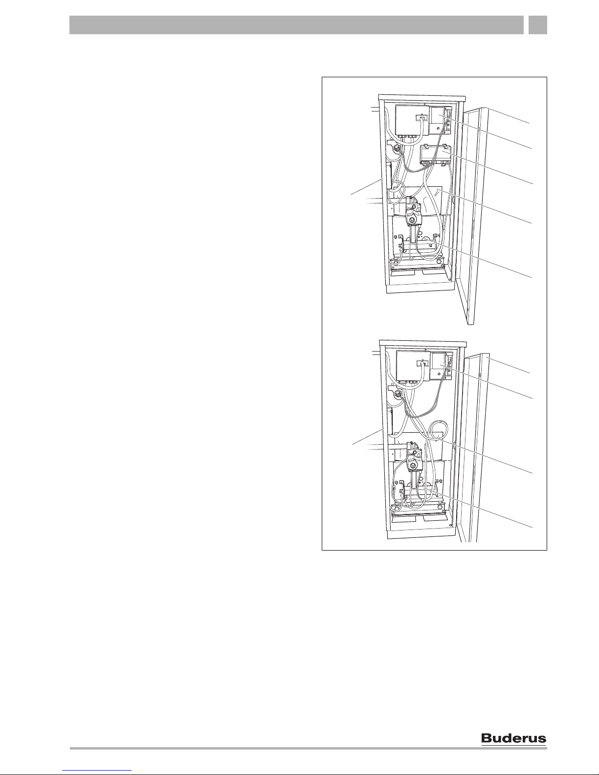
2 Product Description
The boiler is a low temperature gas boiler.
The boiler consists of the following main components:
– Ignition module (GC124 II only) and adjustable
aquastat
– Boiler jacket and front door
– Boiler block with insulation
– Burner
The ignition module and adjustable aquastat monitor
and control all electrical and operational components of
the boiler.
The boiler jacket prevents energy loss and acts as
soundproofing.
The boiler block transfers the heat generated by the
burner to the heating water. The insulation reduces
energy loss.
Fig. 1 Logano GC124 II/SP gas boiler
1 Boiler front door
2 Aquastat (boiler temperature controller)
3 Ignition module (GC124 II only)
4 Boiler block with insulation
5 Burner
6 Boiler jacket
7 747 000 511-01.0K
6
1
5
3
4
2
GC124 II
GC124 SP
6
1
5
4
2
8
Installation and maintenance instructions Gas Boiler Logano GC124 II/SP • Issue 07/2006
We reserve the right to make any changes due to technical modifications
Dimensions and Connections3
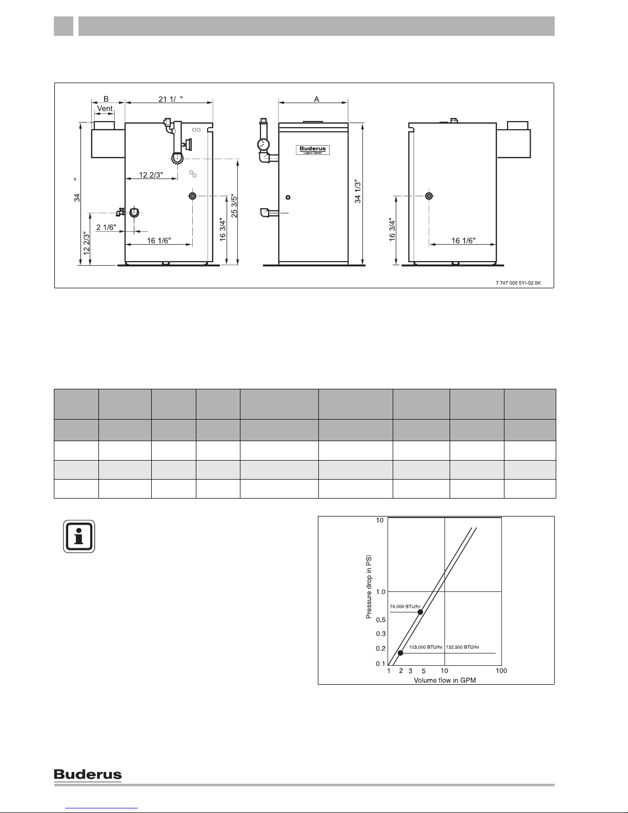
3 Dimensions and Connections
Tab. 1 Dimensions/specs for GC124 II and GC124 SP
Fig. 2 Back, side and front view, measurements in inches
* optional connection
RK 1¼"
VK 1¼"
GAS ½"
EL ¾"
(GAS ½")*
Connections (measurements see the following tables):
VK = Boiler supply
RK = Boiler return
EL = Boiler drain
GAS = Gas connection
Boiler
size
Boiler
input
A B Vent connection
II/SP
Min. relief valve
capacity
Number of
Orifices
Water
volume
Dry
weight
Btu/hr Inches Inches Inches lb/hr Qty. US Gal. lbs
18/3 74000 13 1/8" 8" 5" 62 2 2.4 228
25/4 103000 16 3/4" 8 2/3" 5" 86 3 2.9 287
32/5 132500 20 3/8" 9 1/2" 6" 110 4 3.4 349.5
Fig. 3 Pressure drop/boiler
USER NOTE
For the size and dimensions of the main
gas orifices, refer to Î Chapter 18,
page 79.
Scope of delivery 4
9
We reserve the right to make any changes due to technical modifications.
Installation and maintenance instructions Gas Boiler Logano GC124 II/SP • Issue 07/2006
4 Scope of delivery
z Check packaging upon receipt of delivery for dam-
age.
z Check delivery for completeness.
Component Qty Packaging
method
Boiler, complete 1 1 palette
B-kit components:
- 1-1/4" supply manifold
- 30 psi relief valve
- long shank boiler drain (¾")
- ¼" pressure/temperature
gauge
- 90°-elbow (1¼" x 1" NPT)
- 90°-elbow (1¼" x 1¼" NPT)
- 90°-elbow (¾" NPT nipple)
- nipple1" NPT
- nipple 1¼" NPT
1 1 cardboard
box
1
Vent damper 1 1 cardboard
box
1
Circulator with whip 1 1 cardboard
box
1
Technical documents 1 plastic pack-
age
Tab. 2 Scope of delivery
1
On Palette
Accessory Qty
Cleaning Brush 1
Tab. 3 Scope of delivery
10
Installation and maintenance instructions Gas Boiler Logano GC124 II/SP • Issue 07/2006
We reserve the right to make any changes due to technical modifications.
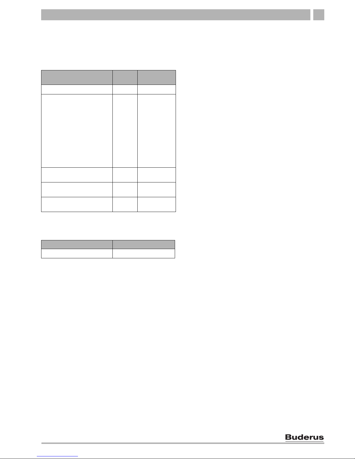
Moving the boiler5
5 Moving the boiler
This chapter describes how to move the boiler safely
into place.
5.1 Moving the boiler with boiler cart
Move the boiler with packaging in tact and on its pallet
as much as possible.
z Remove packaging straps and cardboard box from
pallet.
z Remove screws that secure the boiler base to the
wood pallet.
z Pick up boiler base from one side and slide to the
edge of the pallet. Place a steel pipe as roller under
the boiler base. Place additional steel pipes under
the boiler base and roll the boiler to its final destination.
CAUTION!
SYSTEM DAMAGE
Due to uneven and rough surfaces.
z Observe the transport diagrams on the
packaging to protect the sensitive components from damage due to rough surfaces. Handle the product with care.
USER NOTE
z Protect all boiler connections from dirt if
the boiler is not installed immediately
following removal from packaging.
USER NOTE
Dispose of the packaging material in an
environmentally prudent fashion.
Fig. 4 Moving the boiler with rollers
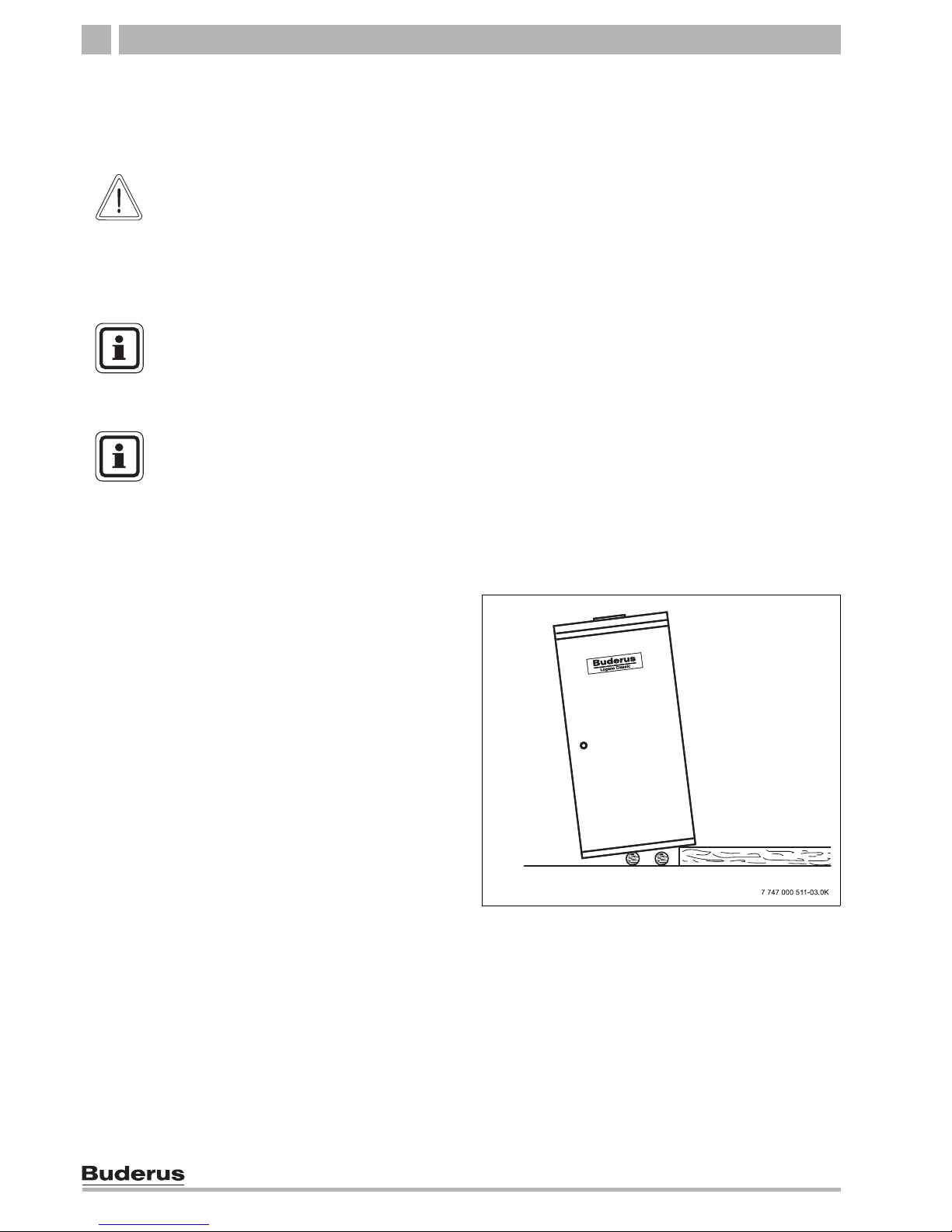
Moving the boiler 5
11
We reserve the right to make any changes due to technical modifications.
Installation and maintenance instructions Gas Boiler Logano GC124 II/SP • Issue 07/2006
z Set the boiler cart or dolley on the front side of the
boiler and put a piece of cardboard between the two
to prevent scratches.
z Secure boiler on the boiler cart.
z Move boiler to desired location.
z Place the boiler at its final postion.
5.2 Lifting and carrying the boiler
The boiler can be picked up at the both long sides of the
boiler as shown.
Fig. 5 Moving the boiler with dolley or boiler cart.
1 Additional card board for protection.
1
CAUTION!
RISK OF INJURY
due to improper securing of the boiler during transport.
z Use a boiler coart or dolley and strap
for moving the boiler
z Secure boiler on the boiler cart.
z Remove the front door during lifting or
transport to prevent unintentional opening.
Fig. 6 Lifting and carrying the boiler
7 747 000 511-04.0K
CAUTION!
RISK OF INJURY
due to carrying heavy loads.
z Lift and carry the boiler with at least four
people at the designated side panel locations.
12
Installation and maintenance instructions Gas Boiler Logano GC124 II/SP • Issue 07/2006
We reserve the right to make any changes due to technical modifications.
Placing the boiler6
6 Placing the boiler
This chapter explains how to place the boiler and position it in the boiler room.
The boiler is very heavy when filled with water. Check
that the floor can bear the weight before installation.
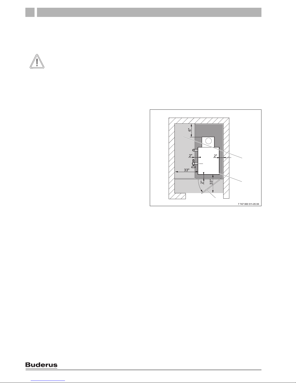
6.1 Clearances
The GC124 boiler is approved for closet installation.
The following minimum distances must then be maintained:
– front: 2",
– sides: 2",
– behind open draft hood: 6",
– above boiler top panel: 30".
A space of at least 33 inches is recommended in front of
the boiler with the door removed to allow sufficient access space for operation and maintenance. When the
door is closed, a minimum clearance of 2 inches is required at the front and sides, 2 inches clearance is also
required for the flue pipe and 30 inches clearance to the
ceiling. The installation location and the base must be
smooth and horizontal.The boiler may be installed on
a flammable base, but not on carpet.
6.2 Leveling the boiler
Level the boiler in both horizontal directions.
z Level the boiler using a level and place small wedges
(not supplied) for leveling purposes.
CAUTION!
SYSTEM DAMAGE
due to frost.
z Place the boiler in a frost-free room.
Fig. 7 Required clearances in the boiler room
1 Recommended service clearances
2 Required minimum clearances
3 Burner tray access door with combustion air opening as
required per ANSI Z.223.1
1
2
3

Boiler installation 7
13
We reserve the right to make any changes due to technical modifications.
Installation and maintenance instructions Gas Boiler Logano GC124 II/SP • Issue 07/2006
7 Boiler installation
This chapter describes how to install the boiler. This includes the following tasks:
– Connecting the heating system
– Electrical connection
– Gas supply piping connection
7.1 Preparing for installation
z Unpack all boxes and containers and check all parts
against the packing lists to make sure that everything
has been supplied.
USER NOTE
Every boiler is carefully inspected and
tested before it leaves the factory. However, if you discover any damage or missing parts, please inform your supplier immediately. Before disposing of packing
material, make sure that no parts are still
in it.
USER NOTE
For better access remove the front door.
14
Installation and maintenance instructions Gas Boiler Logano GC124 II/SP • Issue 07/2006
We reserve the right to make any changes due to technical modifications.
Boiler installation7
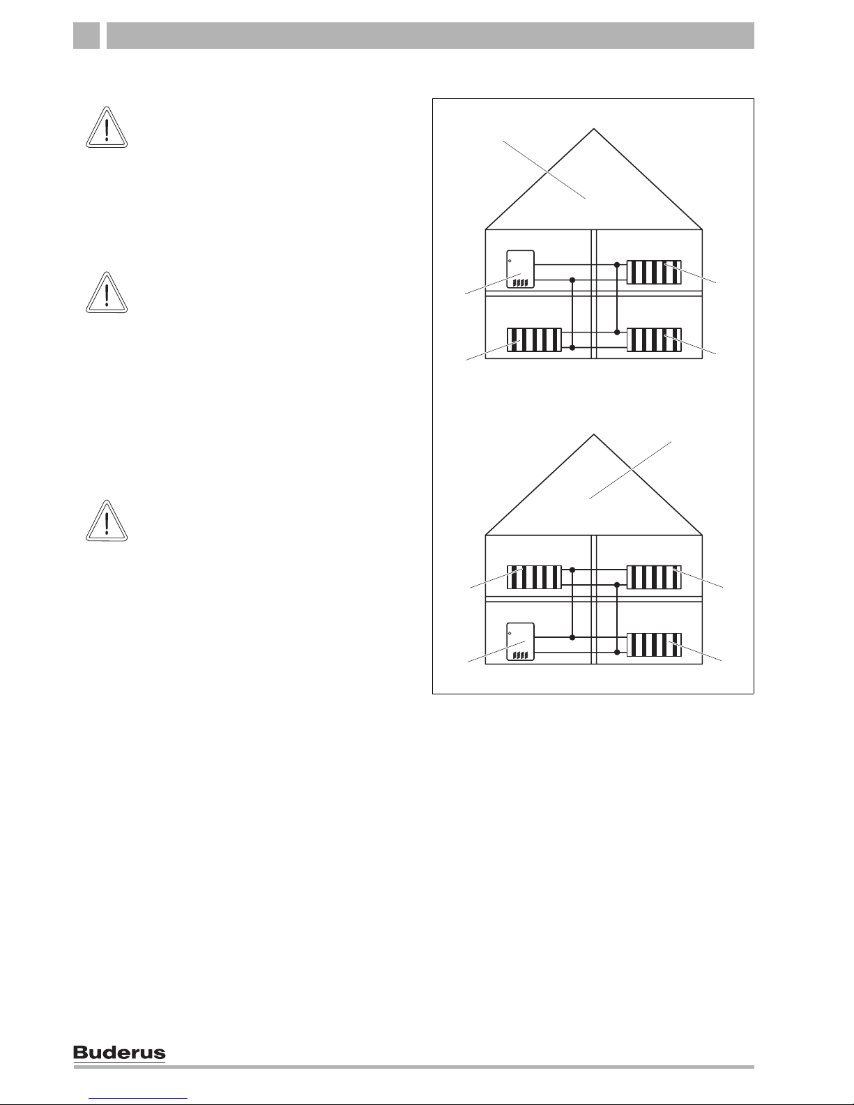
7.2 Connecting the heating system
Fig. 8 Low-water cut-off installation
1 Boiler
2 Radiator
3 Heating system with low-water cut-of
4 Heating system without low-water cut-off
1
2
2
1
2
2
2
2
3
4
CAUTION!
BOILER DAMAGE
Due to moisture.
z Protect the components of the gas igni-
tion system from moisture (dripping,
spray, rain) during installation of the
boiler, during operation and during
maintenance work (such as replacing
the pump, replacing the control, etc.).
CAUTION!
SYSTEM DAMAGE
Due to overheating as a result of a low water condition.
z Note that a boiler installed above the
level of the heating system must be
equipped with a low-water cut-off. The
low-water cut-off must be installed during installation of the boiler and placed
above the water level in the boiler without any means of shutting the water off
between the boiler and low water
cut-off (Î Fig. 8).
CAUTION!
SYSTEM DAMAGE
Due to high temperature variations in the
heating system.
z If the boiler is operated in connection
with a refrigeration system, make sure
that the pipes for the refrigerated liquid
are connected in parallel to the boiler
system with suitable valves to prevent
the refrigerated liquid from entering the
boiler.
z The piping system of a boiler connect-
ed to the heating coils of hydro-air heating systems that may be exposed to the
circulation of cooled air must be
equipped with a flow-control valve or
some other automatic system for preventing the boiler water from circulating
by gravity during the cooling cycle.
Boiler installation 7
15
We reserve the right to make any changes due to technical modifications.
Installation and maintenance instructions Gas Boiler Logano GC124 II/SP • Issue 07/2006
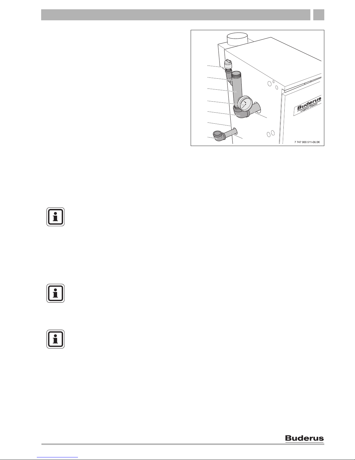
Installation of B-kit
The relief valve and the pressure/temperature gauge are
mounted on the boiler supply manifold which is attached
to the VK (supply) connection of the boiler (included in
B-kit).
Installing boiler supply VK:
z Remove factory installed plastic inserts from boiler
supply (VK), boiler return (RK) and boiler drain (EL)
connections.
z Install the 1¼"NPT nipple into boiler supply, the 1"
NPT nipple into boiler return and ¾" male NPT drain
valve into boiler drain connection.
z Install 90° 1¼" x 1¼"NPT on 1¼"
NPT supply nipple
and face upward and install 90° 1¼" x 1"NPT elbow
on return nipple and face in desired direction.
z Install GC124 1¼" x 1¼"NPT supply manifold into
supply connection (VK) of the boiler. Do NOT place
on return connection of the boiler!
z Install first 90° ¾" street elbow in upper ¾" NPT tap-
ping of GC124 1-1/4" supply manifold and install
pressure relief valve into this ¾" tapping. Make sure
to orient the discharge of the relief valve horizontally.
Install the temperature/pressure gauge in the lower
3/4" tapping of the supply manifold.
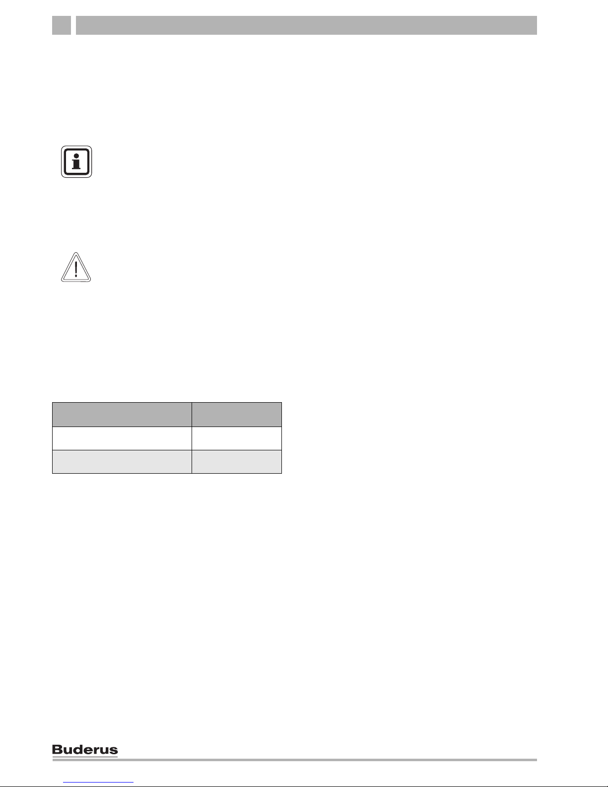
Fig. 9 Installation of B-kit
1 Pressure relief valve ¾"
2 90° 3/4" street elbow
3 GC124 1-1/4" supply manifold
4 Pressure & temperature gauge
5 90° 1-1/4" NPT elbow
6 1-1/4" NPT nipple
7 Boiler drain ¾" NPT (backside of boiler)
8 90° 1-1/4" x 1" NPT elbow
9 1" NPT nipple
1
2
4
5
8
VK
RK
6
9
EL
7
3
USER NOTE
Install the relief valve after the leak test.
(Î Chapter 7.5, page 20).
The relief valve must be installed in a vertical position.
The relief valve must also be installed in
accordance with the requirements of the
ANSI/ASME Boiler and Pressure Vessel
Code, Section IV.
USER NOTE
We recommend installing a y-strainer (accessory) in the boiler return connection to
reduce build-up of debris on the water
side inside the boiler.
USER NOTE
Ensure compliance with all state and local
regulations pertaining to the installation of
boiler systems.

16
Installation and maintenance instructions Gas Boiler Logano GC124 II/SP • Issue 07/2006
We reserve the right to make any changes due to technical modifications.
Boiler installation7
7.3 Electrical connections
The electrical connections of the boiler must be made as
specified by the local codes and the current regulations
of the National Electrical Code, ANSI/NFPA–70.
The boiler must be grounded as specified by the regulations of the relevant local authorities; otherwise follow
the regulations of the National Electrical Code,
ANSI/NFPA–70.
The boiler is fully functional with the factory installed
aquastat and the field installed vent damper and heating
system circulation pump.
Power supply connection.
Install incoming power to the boiler per local and state
codes.
z Install an ON/OFF switch near the boiler per local
code requirements.
CAUTION!
FIRE DANGER
due to exposure to hot water pipes.
z Maintain a minimum clearance of two
inches between non-insulated pipes
carrying hot water and combustible
walls and surfaces in the boiler room.
A minimum of 1" high quality pipe insulation is required to permit direct contact with combustible surfaces.
USER NOTE
When making the electrical connections
please observe the following guidelines:
z Perform only electrical work, if you pos-
sess the required certification for such
work. When you do not have the required certification, have the electrical
work performed by a certified electrician.
z Observe all local and state installation
regulations.
Fig. 10 ON/OFF switch (emergency shutoff switch)
Boiler installation 7
17
We reserve the right to make any changes due to technical modifications.
Installation and maintenance instructions Gas Boiler Logano GC124 II/SP • Issue 07/2006
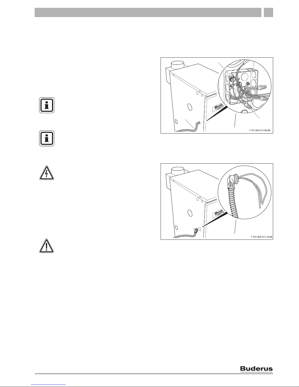
Description of field installed wiring connections
using factory supplied junction box.
z Remove two knock-outs from the left side of boiler
panel to route electrical feed and pump power into
junction box.
z Route electrical power from the outside into junction
box.
z Install a metal strain relief for the incoming power line
on outside of left boiler jacket panel. (Î Fig. 12).
z Just use supplied wiring nuts and double proper wir-
ing before powering up the boiler.
z Check that the heating system functions correctly af-
ter any maintenance work.
Fig. 11 Electrical junction box
1 Electrical junction box (Inside of jacket cabinet)
2 Incoming line voltage wiring
3 Furnished wiring nuts.
2
1
3
USER NOTE
When making the electrical connections
use only wires that are approved for electrical use.
USER NOTE
Refer to the wiring diagrams on pages
Î page 80 bis Î page 82 for electrical
details.
Fig. 12 Strain relief for shielded electrical wiring
WARNING!
RISK TO LIFE
from electrical shock.
z When conducting maintenance work
label all cables before disconnecting
them.
z If cables are connected incorrectly the
system may not operate correctly with
possibly dangerous consequences.
WARNING!
FIRE DANGER
Hot boiler components may damage electrical wiring.
z Make sure that all cables are routed in
the ducts or on the boiler insulation.

18
Installation and maintenance instructions Gas Boiler Logano GC124 II/SP • Issue 07/2006
We reserve the right to make any changes due to technical modifications.
Boiler installation7
7.4 Fuel gas supply connection
7.4.1 Gas connections
For the gas pipe diameter required for the installation
please see Î Tab. 4 and Î Tab. 5. Make sure that the
pipe fitting has the correct thread size.
Make sure that a sediment trap is installed at the inlet for
the gas supply pipe to the boiler. A manual stop valve
must be installed outside the boiler jacket if required by
the local code. We recommend installing a manual
shut-off valve in the main gas pipe to the boiler. The gas
pipe must be fastened outside the boiler.
The local codes must be observed during installation of
the gas piping connections, otherwise the regulations of
the National Fuel Gas Code, ANSI Z 223.1 must be followed.
z Install gas piping without any undue stress on the
piping.
z The Commonwealth of Massachusettes prohibits the
use of copper tubing for the gas line.
Gas carrying capacity (refer to technical manual Î Chapter 18, page 79)
Tab. 5 Gas pipe supply volume
1 Maximum gas supply volume in cubic feet per hour, based on
a specific gas weight of 0.60 and a gas pressure of 0.5 psi or less
and a pressure gradient corresponding to a water column of
0.3 inches.
Fig. 13 Gas piping connection to gas valve – right or left side
1 Gas feed
2 Manual shut-off valve
3 Sediment trap
1
2
3
WARNING!
DANGER OF EXPLOSION
Leakage from the gas pipes and gas
connections may cause an explosion.
z Use soap solution to find leaks.
Nominal
diameter of
iron pipe
(inches)
Equivalent lengths for pipe fittings in
feet
Pipe fitting type
90°-
angle
T-piece
Shut-off
valve
Gas
shut-off
Equivalent lengths in feet
1/2 1.4 2.7 0.3 0.80
3/4 2.1 4.1 0.5 1.25
1 2.6 5.2 0.6 1.6
1 1/4 3.5 6.9 0.8 2.15
1 1/2 4.0 8.0 0.9 2.50
Tab. 4 Equivalent lengths for pipe fittings
Length
of pipe
in feet
Gas pipe supply volume in cubic feet of gas
per hour
1
1/2 3/4 1 1 1/4 1 1/2
10 132 278 520 1060 1600
20 92 190 350 730 1100
30 73 152 285 590 890
40 63 130 245 500 760
50 56 115 215 440 670
75 45 93 175 360 545
100 38 79 160 305 480
150 31 64 120 250 380

Boiler installation 7
19
We reserve the right to make any changes due to technical modifications.
Installation and maintenance instructions Gas Boiler Logano GC124 II/SP • Issue 07/2006
Disconnect the boiler with the manual shut-off valve and
physically separate the boiler from the gas piping if the
gas piping system is pressure tested with a test pressure
greater than 1/2 psi.
If the gas supply pipe system is pressure tested at a test
pressure of 1/2 psi or less, it is sufficient to disconnect
the boiler from the gas pipe system by closing the manual shut-off valve.
Use only sealant that is resistant to corrosion by LPG for
pipe connection. Only a small amount of sealant must be
applied to the external thread of the pipe connections.
If you wish to convert the boiler to propane, please contact Buderus for the required conversion components.
Do not attempt to convert the boiler without the approved Buderus propane conversion parts and the relevant technical documentation. The technical documentation is included with the propane conversion parts.
7.4.2 Installation at high altitudes
The boiler is designed for installation at altitudes below
8500 feet above sea level.
USER NOTE
If the installation location is over 8500 feet
above sea level, please contact Buderus
for another product option as the GC124
is not approved above 8500 feet operation.
CAUTION!
SYSTEM DAMAGE
due to dirt.
If the boiler is assembled and not in use,
note the following:
z Protect the boiler connections from dirt
by closing the connections.
20
Installation and maintenance instructions Gas Boiler Logano GC124 II/SP • Issue 07/2006
We reserve the right to make any changes due to technical modifications.
Boiler installation7
7.5 Filling heating system and checking
for leaks
The boiler is tested for leaks at the factory. Before placing the heating system into use, check the entire system
for soundness to avoid leaks occurring during operation.
Water treatment
Carry out the leak test at 1.5 times the normal operating
pressure and as specified by the local codes as follows:
USER NOTE
Have the water analyzed before filling the
heating system. The water may require
treatment as a result of the analysis.
Please consult the local water supply
company if the water is extremely hard or
has a pH level below 7.0.
CAUTION!
SYSTEM DAMAGE
due to overpressure during the leak test.
Pressure, control or safety components
may be damaged by high pressure.
z Before conducting the leak test make
sure that no pressure, control or safety
components that cannot be disconnected from the water compartment of the
boiler are installed.
Maximum operating pressure Maximum test
pressure
30 psi (based on supplied re-
lief valve)
45 psi
58 psi (with special relief
valve)
75 psi
Tab. 6 Pressure Test
Boiler installation 7
21
We reserve the right to make any changes due to technical modifications.
Installation and maintenance instructions Gas Boiler Logano GC124 II/SP • Issue 07/2006
z Close connection for relief valve (Î Fig. 14) and all
other open connections with plugs.
z Disconnect the expansion tank from the system by
closing the expansion tank shut-off valve.
z Open mixing and shut-off valves on hot water side.
z Fill boiler slowly with water from the feed water con-
nection.
z Open automatic vents slightly to allow the air to es-
cape.
z Slowly fill heating system. Observe pressure display
on pressure gauge during this process.
z Check connections and pipes for leaks.
z Bleed heating system through the bleed valves on
the radiators or other air elimination components or
high points in the system.
z If the pressure drops during air bleeding, water must
be added.
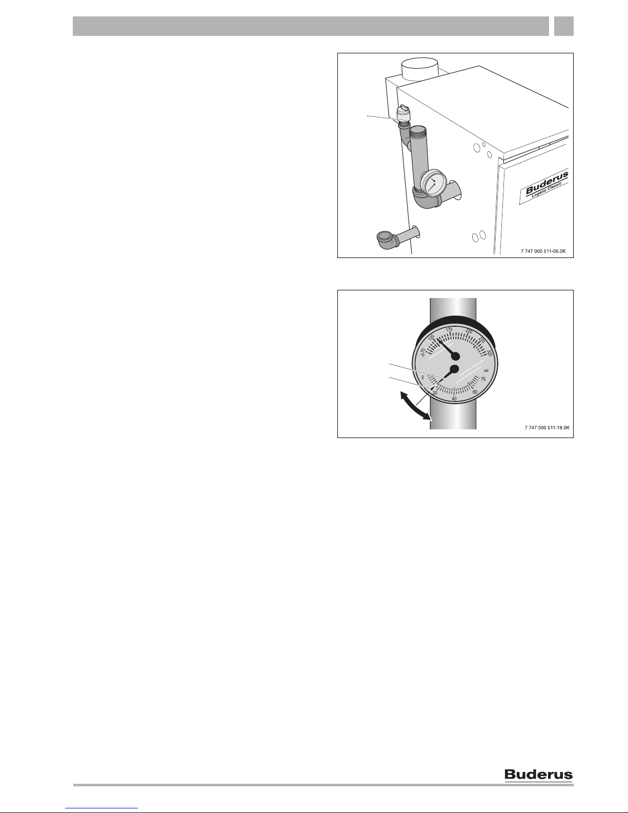
z Install pressure relief valve (Î Fig. 14).
z Open fill valve for additional filling.
z Set static system pressure to at least 15 psi at indi-
cated on pressure relief valve (Î Fig. 15).
z Close fill valve and remove fill hose for fill valve.
Fig. 14 B-kit installation
1 Pressure relief valve ¾"
1
VK
RK
EL
Fig. 15 Pressure temperature gauge
1 Pressure gauge
2 Set pressure mark
1
2
Check openings for combustion air supply and venting8
22
Installation and maintenance instructions Gas Boiler Logano GC124 II/SP • Issue 07/2006
We reserve the right to make any changes due to technical modifications.
8 Check openings for combustion air supply and venting
To ensure an adequate combustion air supply and
venting of the heating system suitable measures must
be taken in accordance with the National Fuel Gas
Code, Section 5.3, Air for Combustion and Ventilation,
or the local codes.
Total air supply from inside the building
Make sure that the boiler room has two permanent
openings that are connected with one or more other
rooms. When calculating the cross-section areas of the
openings, the total combustion output of all gas-fired
appliances in the connected rooms must be taken into
account. Each opening must have a minimum crosssection of one square inch per 1000 Btu/h of the total
combustion output of all gas-fired appliances inside the
connected rooms. Note that the minimum cross-section
of every opening must not be less than 100 square
inches. One opening must not be more than 12 inches
from the ceiling and the other must not be more than 12
inches from the floor of the boiler room, calculated from
the outer edge of the opening. The shortest dimension
of all inlet and outlet openings must not be less than
three inches.
Total air supply from outside the building
Make sure that the boiler room has two permanent
openings, one of which must not be more than 12 inches
from the ceiling and the other must not be more than
12 inches from the floor of the boiler room, calculated
from the outer edge of the opening. The openings have
a direct connection or a connection through ventilation
ducts to the outside or to rooms that have an
unobstructed connection to the outside (crawl space or
attic). The shortest dimension of all inlet and outlet
openings must not be less than three inches.
1. If there is a direct connection to the outside, each
opening must have a minimum cross-section of one
square inch per 4000 Btu/h of the total combustion
output of all gas-fired appliances inside the closed
room.
2. If there is a connection to the outside through
vertical ventilation ducts, each opening must have a
minimum cross-section of one square inch per 4000
Btu/h of the total combustion output of all gas-fired
appliances inside the closed room.
3. If there is a connection to the outside through
horizontal ventilation ducts, each opening must have
a minimum cross-section of one square inch per
2000 Btu/h of the total combustion output of all gasfired appliances inside the closed room.
4. If the openings are connected to ventilation ducts,
the ducts must have the same cross-section area as
the openings.
CAUTION!
BOILER DAMAGE AND OPERATING
FAULTS
due to missing or inadequate openings for
combustion air and venting of the boiler
room.
Inadequate venting of the boiler room may
result in excessive ambient temperatures.
This can damage the boiler.
Inadequate combustion air supply may
cause operating faults.
z Make sure that inlets and outlets are
not reduced or closed and that they are
adequately dimensioned.
z If faults are not corrected immediately,
the boiler must not be operated
z Inform the system operator of the fault
and the danger.
CAUTION!
BOILER DAMAGE
due to contaminated combustion air.
z Never use cleaning agents that contain
chlorine and halogenated
hydrocarbons (e.g. spray bottles,
solvents and cleaning agents, paints,
glues).
z Do not store or use these substances in
the boiler room.
z Prevent excessive dust levels.
WARNING!
FIRE DANGER
due to flammable materials or liquids.
z Do not store flammable materials or
liquids in the immediate vicinity of the
heat generator.

Requirements for connection to chimneys or venting systems 9
23
We reserve the right to make any changes due to technical modifications.
Installation and maintenance instructions Gas Boiler Logano GC124 II/SP • Issue 07/2006
9 Requirements for connection to chimneys or venting systems
The flue connection must comply with the regulations of
the National Fuel Gas Code, Part 7, Venting of
Equipment, and the local construction codes.
Flue connections of heating systems with natural
venting must not be connected with any component of a
mechanically operated venting system that operates
with overpressure.
The cross-section of the flue connection must not be
less than that specified in Tab. 1, page 8.
If the boiler is to be connected to a brick chimney, the
chnimney must be thoroughly inspected before use. The
chimney must be clean, in compliance with construction
codes and of sufficient dimensions.
Chimneys with an internal liner are preferred and are
only permitted if the liner complies with all national, state
and local construction codes. Liners of fire-glazed brick
with moisture-proof joints and liners of corrosionresistant material are recommended. Contact the local
gas supply company for advice and recommendations
for flue connection and chimney liners. A flue pipe of
single-walled sheet metal is required for flue
connections for type II models.
An adequate chimney height in compliance with the
tables of the National Fuel Gas Code, ANSI Z 223.1, is
required.
Separation of a boiler from a common flue system
If an existing boiler is separated from a common venting
system, the venting system will then be too large to
guarantee correct venting for the heating systems that
remain connected to the system.
Test the venting system by the following procedure:
Carry out these steps with every heating system that
remains connected to the venting system when the
boiler is separated from a common venting system.
Every heating system must be started in operation and
the other heating systems must remain turned off.
A All unused openings of the common system must be
sealed.
B Inspect the venting system to ensure that it has the correct
dimensions and longitudinal inclination. Make sure that the
system is not blocked, leaking, corroded or has any other
faults that cause it to operate improperly.
C If necessary, close all doors and windows in the building
and all doors between the space in which the heating
systems that remain connected to the venting system are
installed and the other rooms of the building. Turn off
washing machines and dryers and all appliances that are
not connected to the venting system. Run all venting fans
and bathroom exhaust fans at maximum speed. Fans in
use in summer must remain in operation and oven exhaust
system flaps must be closed.
D Now start the heating system that is to be tested. Follow the
instructions for starting. Set the thermostat for continuous
operation.
E After the main gas burner has been operating for five
minutes, check the opening at the back flow check for
drafts with a match flame or a candle, or with the smoke of
a cigarette, cigar or pipe.
F Then all heating systems that remain connected to the
venting system have been checked as above to ensure
that the venting operates properly, return all doors,
windows, exhaust fans, oven exhaust flaps and all other
gas-fired appliances to their original position.
G Any incorrect status of the common venting system must
be corrected to ensure that the heating system complies
with the regulations of the National Fuel Gas Code, ANSI Z
223.1. If the size of any component of the common venting
system is changed, the complete venting system must be
resized to comply with the relevant tables in Part 11 of the
National Fuel Gas Code, ANSI Z 223.1.

24
Installation and maintenance instructions Gas Boiler Logano GC124 II/SP • Issue 07/2006
We reserve the right to make any changes due to technical modifications.
Flue pipe installation10
10 Flue pipe installation
This section describes the connection of the flue pipe
and venting system.
Note that the open draft hood cannot be modified under
any circumstances.
1. The flue collar is factory installed on the flue
connection of the open draft hood and fastened with
four (4) corrosion-resistant sheet metal screws.
The vent damper supplied with the boiler must be used
for venting the boiler only.
The position of the vent damper position blade must be
visible.
The open draft hood must be at least six inches from all
combustible surfaces.
The vent damper must be freely accessible for
maintenance.
The vent damper must be open when the main burner of
the boiler is operating.
Installation of vent damper
2. Install pins in the hole of the vent damper blade for
the II models only. The openings in the vent damper
blade must remain open for the SP model boilers.
3. Fasten vent damper to the flue collar of the open
draft hood with three (3) corrosion-resistant sheet
metal screws.
Connecting flue pipe
4. Connect flue pipe to the chimney with the shortest
possible length of flue pipe.
Use only flue pipes with the proper diameter for the
boiler.
Every horizontal section of the flue pipe must have a
minimum rise of 1/4 inch per foot towards the chimney.
The flue pipe must be securely fastened to prevent it
from hanging. A support must be installed at least every
five feet. Fasten every connection with at least three (3)
corrosion-resistance sheet metal screws.The end
section of the flue pipe must connect to the inside of the
chimney smoke duct.
Fig. 16 Installation of vent damper
1 Open draft hood
2 Vent connection
3 Vent damper
4 Damper blade position indicator
5 Vent damper motor
6 Flue gas collector
7 Boiler
5
6
7
4
3
1
2
USER NOTE
z The boiler can and may only be
operated with the electrical vent
damper that is standard supplied with
every GC124.
Flue pipe installation 10
25
We reserve the right to make any changes due to technical modifications.
Installation and maintenance instructions Gas Boiler Logano GC124 II/SP • Issue 07/2006
A minimum clearance of six inches is required between
the flue pipes and all flammable materials.
The vent pipe must not be reduced in size and the
venting system must not be compromised by the
installation of additional appliances.
Electrically connecting the vent damper
5. Disconnect your heating system from the main
electricity supply.
6. Route the connection wiring of the vent damper
along the left side of the boiler into the opening on
the left side of the boiler. Secure strain relief at the
furnished knock-out.
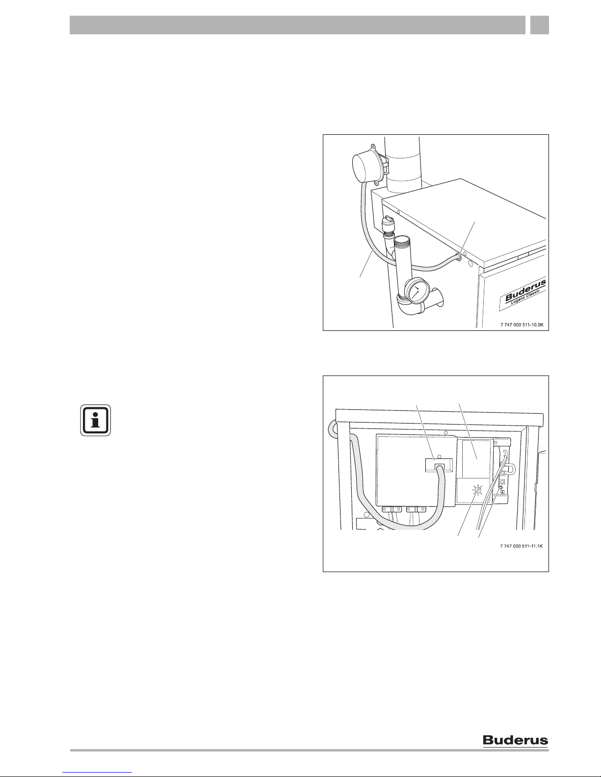
7. Connect vent damper plug into the terminal bar as
shown in the circuit diagram.
Fig. 17 Routing of vent damper wiring
1 Vent damper wiring
2 Vent damper wiring strain relief
1
2
Fig. 18 Connecting vent damper wiring
1 Vent damper connection plug
2 Aquastat
3 Power supply indicator light
4 Aquastat temperature control knob
1
3
2
4
All connection points on the complete
venting system must be checked for correct
installation and sealing immediately after
carrying out one of the installation steps.
The seams and connections must be
checked for gas leaks. Regulations require
the complete venting system to be checked
at least once a year by a qualified
technician after installation and initial
operation.
26
Installation and maintenance instructions Gas Boiler Logano GC124 II/SP • Issue 07/2006
We reserve the right to make any changes due to technical modifications.
Placing the heating system in operation11
11 Placing the heating system in operation
The burner and gas train integrated in the boiler have
been tested at the factory as described in ANSI Z 21.13
to ensure safe operation of the heating system and
verify specific performance indicators.
Preparing for operation
1. Set the room thermostat (optional) to the lowest
setting.
2. Check all combustion air and all flue gas ducts and
openings. (Î Chapter 8 and 9, page 22 and
page 23).
WARNING!
RISK TO LIFE
due to electric shock when the cover
protecting the electric components has
been removed.
Before removing the cover to the electric
components:
z Cut power to the heating system by
turning the emergency shut-off switch
to the OFF position, or by shutting off
the heating system circuit breaker.
z Take precautions to prevent accidental
reactivation.
WARNING!
RISK TO LIFE
from gas poisoning.
Insufficient ventilation can lead to leaking
of flue gases.
z Verify that all combustion air and all
flue gas openings are wide open and
not obstructed.
z The boiler must not be placed in
operation unless all deficiencies have
been removed.
z Inform the owner and operator of the
heating system of any deficiencies in
writing.
 Loading...