

Buderus Logano GB125/22 BE, Logano GB125/35 BE, Logano GB125/30 BE Installation And Service Instructions Manual
Installation and Service
Instructions
Low Emissions and
High Efficiency
Condensing Oil Boiler
CAUTION!
Observe the safety instructions of this installation
and maintenance manual before placing the boiler
in operation.
DANGER!
Installation, adjustment, modification, operation or
maintenance of the heating system carried out by
an unqualified person may result in danger to life
and limb or property damage.
The directions of this installation and maintenance
manual must be followed precisely.
Contact a trained and certified service company or
service provider if support or additional information
is required.
CAUTION!
The operating manual is a component of the technical documentation and must be handed over to the
operator of the heating system.
Discuss the instruction in this manual with the owner or operator of the heating system to ensure that
they are familiar with all information required for
operation of the heating system.
Logano GB125 BE US/CA
6 720 615 063 - 05/2009 US/CA
For trained and certified
installers
Please read carefully prior
to installation, maintenance
and service
Contents
Contents
1 Safety instructions and explanation of
symbols 3
1.1 Safety instructions 3
1.2 Explanation of symbols 4
1.3 Standards, regulations and code compliance 5
1.4 Notes on installation and operation 5
1.4.1 Other important information 5
2 Product description 6
2.1 Intended use 6
2.2 Product details 7
2.3 Heating system water quality 8
2.4 Tools, materials and accessories 8
2.5 Package Contents 9
2.6 Dimensions and specifications 10
2.6.1 Logano GB125 BE dimensions 10
2.7 Conditions for operation 11
2.7.1 General operating conditions 11
2.7.2 Boiler room and ambient conditions 12
2.7.3 Fuel conditions 12
2.7.4 Power supply conditions 12
2.7.5 Hydraulic conditions and water quality 12
2.8 Disposal 13
5.8.1 Logamatic control installation 29
5.8.2 Fitting the temperature sensor assembly 30
5.8.3 Power connection and connections of
additional components 31
5.8.4 Fitting cable strain relief 32
5.9 Install the back boiler cover 32
6 Placing the heating system in operation 33
6.1 Bringing the system up to operating pressure 33
6.2 Testing relief valve 34
6.3 Checking position of heat exchanger baffles 34
6.4 Preparing the heating system for operation 34
6.5 Starting up the control and the burner 34
6.6 Taking measurements 35
6.7 Checking the manual reset high limit (STB) 36
6.8 Replacing the burner hood 36
6.9 Commissioning log 37
7 Shutting down the heating system 38
7.1 Normal shut-down 38
7.2 Shutting down the heating system in an
emergency 38
7.2.1 Action in an emergency 38
3Moving the boiler 14
3.1 Reducing the boiler weight for handling
purposes 14
3.2 Lifting and carrying the boiler 15
3.3 Moving the boiler with hand truck 15
4 Placing the boiler 16
4.1 Wall clearances 16
4.2 Reversing the burner door 17
4.3 Mounting the adjustable feet
(included with B-kit) 18
4.4 Positioning and leveling the boiler 18
5 Boiler installation 19
5.1 Flue pipe installation 19
5.2 Test ports 20
5.3 Installation options 22
5.4 Installation of Water Connections 24
5.4.1 Installing B-Kit 24
5.4.2 Installation of boiler drain (included in B-Kit) 25
5.4.3 Installation of system components 25
5.5 Filling heating system and checking
for water leaks 26
5.6 Connecting the fuel supply 27
5.7 Condensate trap 28
5.8 Electrical connections 29
8 Heating system servicing 39
8.1 Why is regular servicing important? 39
8.2 Preparing the boiler for servicing 39
8.3 Cleaning the boiler 40
8.3.1 Cleaning the boiler with cleaning brushes 40
8.3.2 Wet cleaning (chemical cleaning) 41
8.4 Cleaning the heat exchanger system 42
8.5 Cleaning the neutralizer unit and trap 44
8.6 Checking the air supply hose 45
8.7 Check heating system operating pressure 45
8.8 Testing relief valve 46
8.9 Concentric combustion air supply and
flue pipe 46
8.10 Air supply system 46
8.11 Inspection and maintenance reports 47
9 Troubleshooting 50
10 Examples of installations 51
11 Spare parts 53
12 Wiring diagrams 62
Index 63
Logano GB125 BE US/CA - Technical specifications are subject to change without prior notice.2
Safety instructions and explanation of symbols
1 Safety instructions and explanation of symbols
1
1.1 Safety instructions
If you smell flue gas
V Switch off the boiler (Æ page 38).
V Open windows and doors.
V Inform an authorized heating contractor.
Risk of poisoning. Insufficient ventilation may
cause dangerous flue gas leaks.
V Never close off or reduce the size of air inlet or outlet
vents.
The boiler must not be operated until the obstruction
has been removed.
V Ensure that no mechanical air-extraction equipment
draws air from the boiler room, e.g. kitchen vent hood,
clothes dryer, central vacuum system, etc.
V Inform the system operator in writing of an existing
problem and associated danger.
Danger from escaping flue gases
V Make sure that the flue pipes and seals are not dam-
aged.
V Use silicone as sealing compound.
V Never install a barometric nor a thermally controlled
vent damper with this boiler.
V Connect only one boiler to each flue system or chimney
flue.
V The flue system piping must not feed into another air
extraction duct.
V Do not route the flue system piping through or inside
another duct, used for exhausting air or other flue
gases.
V The condensate trap must be primed at all times. Fail-
ure to do so will allow combustion gases to escape into
boiler room.
Danger from electrical shock
V Before opening the boiler:
Disconnect the heating system from the electrical
power supply by means of the emergency shutoff
switch or the heating system circuit breaker on the
main fuse panel.
V It is not sufficient just to switch off the control.
V Take measures to ensure the heating system can not
be switched on again unintentionally.
Installation
V Correct and proper installation and adjustment of the
burner and the controls are the fundamental requirements for safe and economic operation of the boiler.
V The boiler may only be installed and maintained by a
trained and certified heating contractor.
V Do not modify any parts that carry flue gases.
V Only qualified electricians are permitted to carry out
electrical work. Follow applicable code.
V The hot water tank may only be used for heating
domestic hot water.
V Never shut off safety relief valves! Water may
escape from the safety relief valve when the water is
being heated.
DANGER TO LIFE
by failure to consider your own safety in an
emergency such as a fire.
V Never put yourself at risk of fatal injury.
Your own safety must always take the
highest priority.
Dangers posed by explosive and combustible
materials
V Do not use or store combustible materials (paper, lace
curtains, clothing, thinners, paints, etc.) near the boiler.
V Maintain a clearance of 16 inches from the boiler.
Combustion air
V Keep the supply of air for combustion free of corrosive
substances (e.g. halogenated hydrocarbons that contain chlorine or fluorine compounds). In that way you
will prevent corrosion.
Logano GB125 BE US/CA - Technical specifications are subject to change without prior notice. 3
1
Safety instructions and explanation of symbols
Maintenance and service
Heating systems should be regularly maintained for the
following reasons:
– to achieve a high level of efficiency and to operate the
system economically (low fuel consumption),
– to achieve a high level of operational reliability,
– to maintain the cleanest possible combustion.
V Recommendation for users: sign a maintenance
and servicing contract with a trained and certified heat-
ing contractor covering annual servicing and condition-
based maintenance.
V Servicing and repairs should only be carried out by a
trained and certified heating contractor.
V Have any faults immediately corrected in order to pre-
vent damage to the system.
V Use only genuine spare parts. Damage caused by the
use of parts not supplied by Buderus is not covered by
the Buderus warranty.
Instructing the customer
V Explain to the customer how the boiler works and how
to operate it.
V Inform the customer that he/she must not carry out any
alterations or repairs.
1.2 Explanation of symbols
Warnings are indicated by a warning trian-
gle and a grey background.
Signal words are used to indicate the seriousness of the
ensuing risk if measures for minimizing damage are not
taken.
– Caution indicates that minor damage to property may
occur.
– Warning indicates that minor personal injury or severe
damage to property may occur.
– Danger means that severe personal injury may occur.
Very serious cases may result in death.
Notes are identified in the text by this symbol. They are bounded by horizontal lines
above and below the text.
Notes contain important additional information.
Notes do not contain any warnings or information about
hazards or risks.
Cross-references to particular places in the document or
to other documents are marked with an arrow Æ.
Logano GB125 BE US/CA - Technical specifications are subject to change without prior notice.4
Safety instructions and explanation of symbols
1
1.3 Standards, regulations and code
compliance
It is the installers responsibility to ensure the
installation and operation of this heating system meets all applicable federal, state, and
local codes.
The boiler must be installed by a qualified installer and in accordance with all requirements of NFPA-31, "Installation of OilBurning Equipment". Installation must comply with all local and national legal requirements and the regulations of all institutions
having legislative authority with regard to the
installation of oil-fired boilers.
1.4 Notes on installation and operation
When installing and operating the heating system
observe the following:
– The local building codes regarding the installation
– The local building codes regarding combustion air sup-
ply and venting systems, and the chimney connection
– Regulations governing electrical connection to the
mains power supply
– The regulations and standards relating to the safety
systems for the water heating system
1.4.1 Other important information
– Only operate the boiler with the concentric air/venting
system specifically designed and approved for it.
– Follow the local code when connecting the conden-
sate outlet to the public sewer system.
Logano GB125 BE US/CA - Technical specifications are subject to change without prior notice. 5

2
Product description
2 Product description
This installation and maintenance manual contains important information for the safe and correct installation, initial
start-up and maintenance of this boiler.
The Logano GB125 BE oil-fired condensing boiler is generally referred to below simply as the boiler.
These installation and servicing instructions are intended
for trained and certified heating contractors, who – as a
result of their technical training and experience – are
skilled in dealing with heating systems and DHW installations.
This boiler must be installed with one of the Buderus supplied concentric heating systems.
– Concentric direct vent side wall kit
– Concentric vertical kit
– Concentric masonry chimney kit
This boiler produces significant amounts of acidic flue gas
condensate while in operation. Condensate may cause
damage to sewer pipes and septic systems, and disposal
may be subject to local regulations. In the absence of
such regulations Buderus recommends a condensate
neutralization kit.
The boiler must draw all combustion air from the outside.
2.1 Intended use
The boiler is designed for heating central heating system
water and indirect heating of domestic hot water (e.g. in a
hot water tank), for instance in single family homes or multi
family buildings.
Logano GB125 BE US/CA - Technical specifications are subject to change without prior notice.6
2.2 Product details
This boiler is an oil-fired, fan-assisted condensing boiler
with modulating control of boiler water temperature.
The boiler consists of:
– Control panel
– Boiler jacket
– Boiler heat exchanger with insulation
–Burner
– Heat exchanger system
The controls monitor and control all electrical boiler components.
The boiler jacket prevents heat loss and acts as a noise
insulator.
The boiler heat exchanger transfers the heat generated by
the burner to the heating water. The insulation prevents
energy loss.
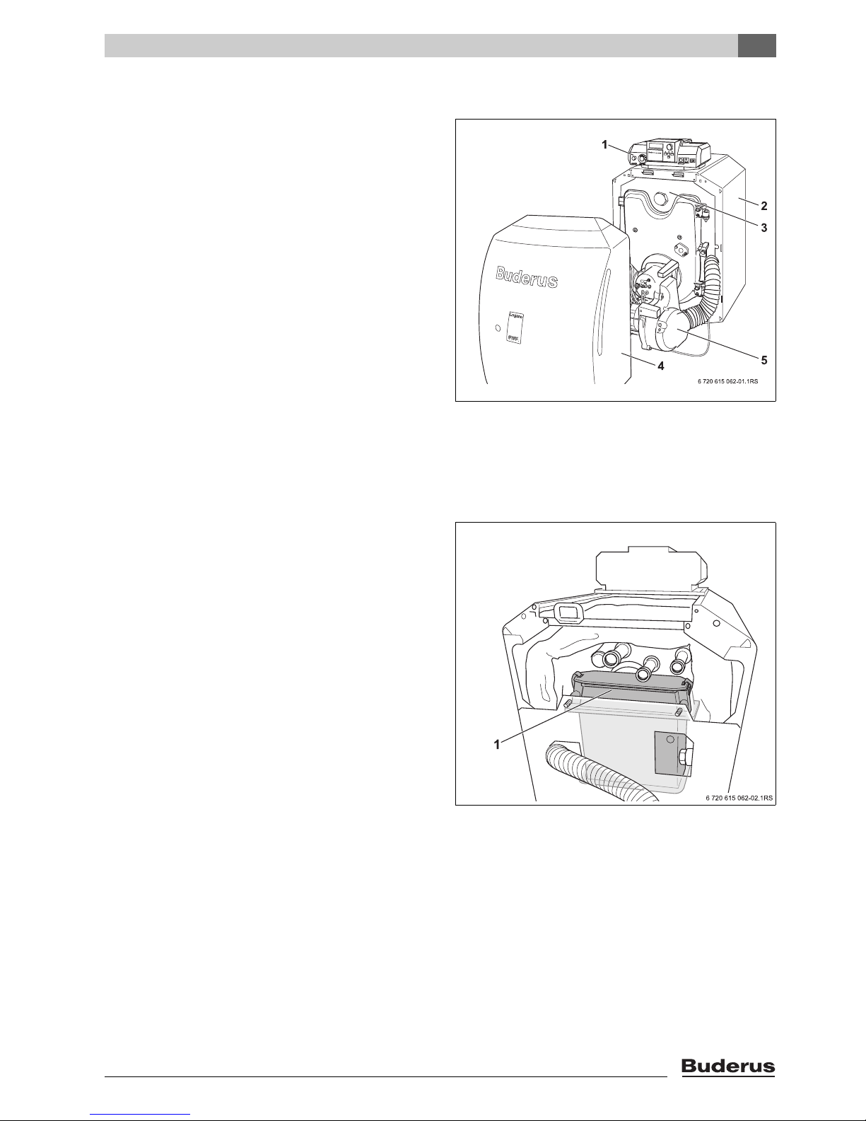
Product description
Fig. 1 Boiler with burner
1 Control panel - Logamatic
2 Boiler jacket
3 Boiler heat exchanger with insulation
4 Burner hood
5 Burner
2
Logano GB125 BE US/CA - Technical specifications are subject to change without prior notice. 7
Fig. 2 Rear view with heat exchanger (thermal insula-
tion not shown)
1 Secondary condensing heat exchanger system
2
Product description
2.3 Heating system water quality
Poor water quality can damage heating systems due to
scale formation and corrosion (Tab. 8).
Caution: Risk of system damage due to unsuitable heating system water.
V If oxygen-permeable pipes are used, e.g.
for radiant heating systems, the systems
must be separated from the boiler by a
heat exchanger. Unsuitable heating system water promotes sludge formation and
corrosion. This can result in heat exchanger malfunction and damage.
2.4 Tools, materials and accessories
For the installation and maintenance of the boiler, you
need standard tools used for central heating and DHW
systems, plus metric wrenches and metric Allen
wrenches.
The following may also prove useful:
– Hand truck with securing strap or Buderus boiler cart
– Wood battens
– Cleaning brushes and/or chemical cleaning agent for
wet cleaning
Logano GB125 BE US/CA - Technical specifications are subject to change without prior notice.8
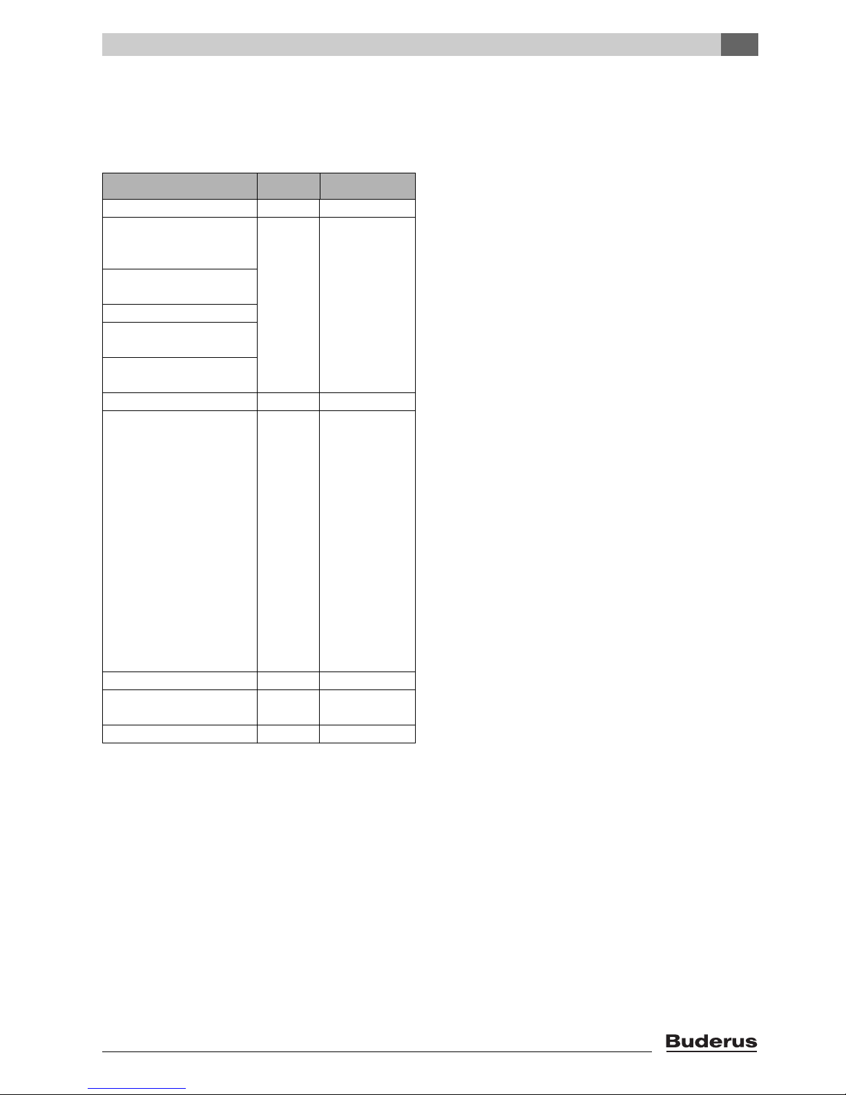
2.5 Package Contents
V Upon delivery, check that the packaging is undam-
aged.
V Check the delivery for completeness.
Component Qty Packaging
Boiler heat exchanger 1 1 pallet
Boiler casing, factory-fit-
ted to boiler heat
exchanger
Burner hood, factory-fitted
to boiler heat exchanger
Heat exchanger system
Oil burner with factory-fitted burner door
Air supply hose, factory-fitted
Condensate trap 1 1 bag
B-kit components:
11 bag
– Conversion nipple
(1¼" NPT)
– 30 psi relief valve
– Boiler drain (¾")
– Pressure/temperature
gauge
– Double nipple
(1¼" NPT × R1¼)
– 90°-elbow (1¼” NPT)
– 90°-elbow (¾" NPT)
– Burner mounting studs
and washers
– Adjustable feet
Logamatic control panel 1 1 box
Tigerloop oil filter and
11 box
deaerator
Technical documentation 1 bag
Tab. 1 Package Contents
1) Under the burner hood
1)
1
)
Product description
2
Logano GB125 BE US/CA - Technical specifications are subject to change without prior notice. 9
2
Product description
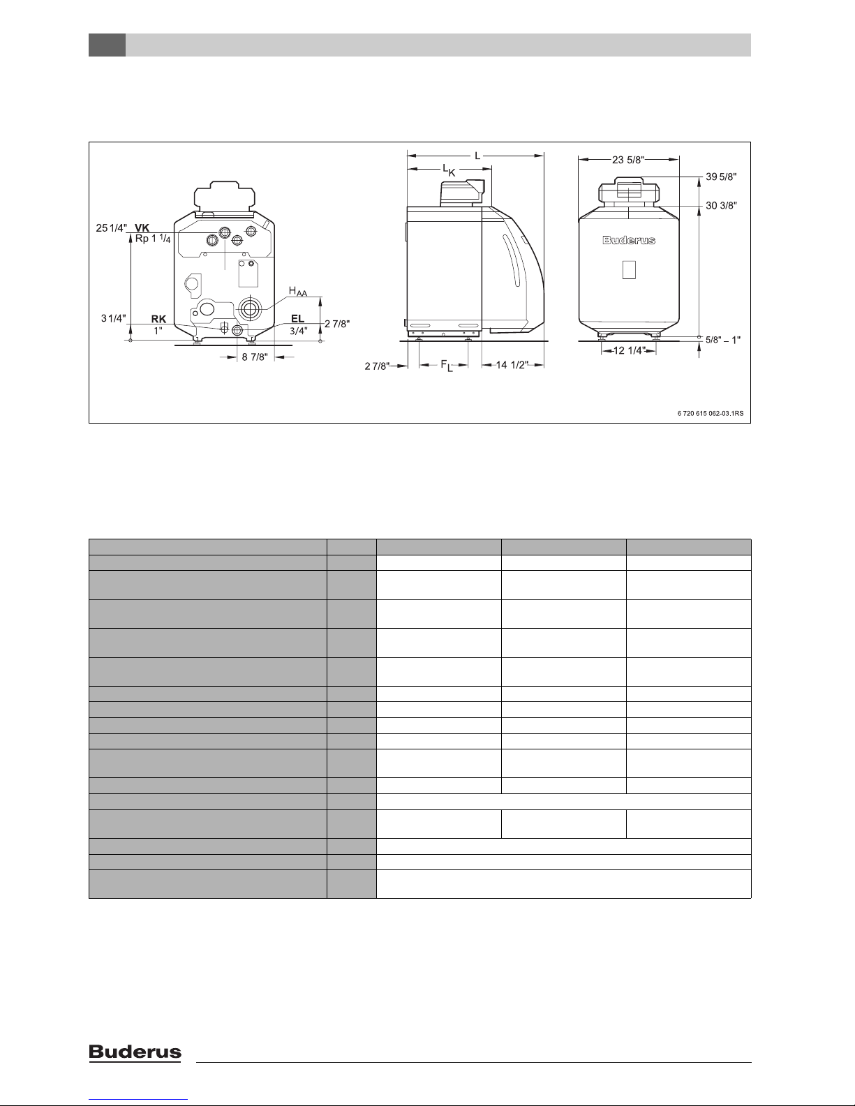
2.6 Dimensions and specifications
2.6.1 Logano GB125 BE dimensions
Fig. 3 Connections and dimensions (measurements in inches)
VK = Boiler supply
RK = Boiler return
EL = Boiler drain (connection for drain valve)
Dimensions and connections:
Boiler model Unit GB125/22 BE GB125/30 BE GB125/35 BE
Boiler sections 344
Rated heat output (gross output)
131/86 °F
Rated heat output (net IBR rating)
131/86 °F
Rated heat output (gross output)
176/140 °F
Rated heat output (net IBR rating)
176/140 °F
Burner input MBtu/hr 81 108 131
AFUE % 91.2 91.1 91.0
Flue gas temperature 176/140 °F °F 176 176 192
Boiler water content gal 8.7 11.8 11.8
Gas volume of combustion chamber and heat
exchanger
Oil firing rate gph 0.60 0.75 0.95
Flue gas back-pressure in. W.C. 0.08" - 0.14" W.C.
Heat exchanger water pressure loss
(DeltaT = 18 °F)
Maximum supply temperature
Maximum operating pressure psi 44
Maximum time constant of thermostat and
high limit safety cut-out (STB)
1)
MBtu/hr 76 102 124
MBtu/hr 67 90 109
MBtu/hr 75 100 121
MBtu/hr 65 87 105
cu.ft. 1.5 2.0 2.0
ft. of
head
°F 212
s 40
1.8' 2.0' 2.7'
Tab. 2 Specifications
1) Safety manual reset high limit (safety temperature limiter, STB)
Maximum permitted supply temperature = Safety limit (STB) – 32 °F
Example: Safety limit (STB) = 212 °F, maximum possible flow temperature = 212 - 32 = 180 °F
The safety limit must meet the national regulations of the country concerned.
Logano GB125 BE US/CA - Technical specifications are subject to change without prior notice.10
Product description
Boiler model Unit GB125/22 BE GB125/30 BE GB125/35 BE
Boiler overall length (L) inch 37 1/2" 42 3/8" 42 3/8"
Boiler block length (LK) inch 25 3/4" 30 ½" 30 ½"
Combustion chamber length inch 16" 20 ½" 20 ½"
Combustion chamber length inch 10 5/8"
Burner door thickness inch 2 1/3"
Distance between boiler feet (FL) inch 16 1/8" 20 7/8" 20 7/8"
Net weight
1)
lbs 423 503 503
Tab. 3 Dimensions, weight and other data for boilers without burners
1) Weight incl. packaging material approx. 6- 8 % more.
2.7 Conditions for operation
Maintaining the specified operating conditions will enable
the boiler to provide a high level of reliability and long service life. Some details relate only to operation with Buderus
Logamatic control panels.
Caution: Ri sk of sy st em da ma ge if ope ra tin g
conditions are not maintained.
Extreme divergence from the stated conditions may cause irreversible damage to individual components of the boiler as a whole.
V The information on the rating plate is defin-
itive.
2
2.7.1 General operating conditions
Operating conditions
Min. boiler water
temperature
In combination with Logamatic control for variable low-temperature operating modes, such as Logamatic 2107
no requirements operating
temperatures are ensured by
the Logamatic controls
2)
Operating interruption
(complete boiler shutdown)
Automatically by Logamatic controls not required but recommended with
Heating circuit with
heating circuit mixer
low-temperature heating system
design 130/113 °F
Required with:
– Underfloor radiant heating systems
– Systems with large water capacity:
> 115 gal/MBH
(1 MBH = 100,000 Btu/hr)
1)
Min. return temperature
No requirements
Tab. 4 General operating conditions
1) A heating circuit with a mixer improves controllability and is specifically recommended for systems with several heating circuits.
2) If heating zones or a boiler circuit actuator cannot be regulated via the control device (for example pump logic), an operating temperature of
122 °F must be reached within 10 min of switching the burner ON by restricting the water volume flow.
Logano GB125 BE US/CA - Technical specifications are subject to change without prior notice. 11
2
Product description
2.7.2 Boiler room and ambient conditions
Operating conditions Notes – Requirement in greater detail
Temperature in the boiler room +40 to +104 °F
relative humidity max. 90 % No condensation or precipitation inside the boiler room
Dust/airborne particles − Excessive dust inside the boiler room must be avoided when the boiler is opera-
Halogenated-hydrocarbon compounds
Small animals − Prevent small animals from entering the boiler room, particularly through the air inlet vents –
Fire safety − Maintain clearances between the boiler and flammable materials in accordance with local
Flooding − In case of an acute risk of flooding, disconnect the boiler in time from the from its fuel and
− The combustion air must be free from halogen-hydrocarbon compounds.
ting, e.g.:
– dust from building work
Combustion air supplied from outside must not be excessively loaded with dust
or airborne seed; if necessary, air filters should be fitted to prevent this:
– Air supply contaminated with dust from dirt roads and paths.
– Air supply contaminated with dust from production and processing facilities, e.g. quar-
ries, mines, etc.
– Airborne particles from thistles and similar
– Identify the source of halogen-hydrocarbon compounds and seal it off. Where this is
impossible, route combustion air from areas that are not contaminated by halogenatedhydrocarbon compounds.
by fitting them with screens.
regulations. A minimum clearance of 16” is required. Never store flammable materials or liquids in the vicinity of the boiler.
power supply before water enters the room. Any general and burner components or control
equipment, which come into contact with water, must be replaced before re-commissioning.
Tab. 5 Boiler room and ambient conditions
2.7.3 Fuel conditions
Country All countries
Fuels #2 Fuel oil ASTM D396-05 Type 2
Remarks The burner may only be operated with the specified fuel.
Clean and service once a year. Check that the entire system functions properly at the same time. Immediately rectify any faults identified.
Approved for B5 Fuel Oil (5% biodiesel (B100) according ASTM D6751)
Tab. 6 Country-specific fuels and remarks
2.7.4 Power supply conditions
Operating conditions Notes – Requirement in greater detail
Mains supply voltage 110 - 120 V The outer casing/boiler must be grounded for safety reasons and in order to function correctly.
Circuit breaker 10 A
Frequency 60 Hz
Enclosure rating − IP 40 (protected against contact by entry of foreign objects > 0.04 inches Ø (> 1 mm Ø ),
no water proofing)
Tab. 7 Power supply
2.7.5 Hydraulic conditions and water quality
Operating conditions Notes – Requirement in greater detail
Operating pressure (above
atmospheric)
Permissible testing pressure 45 – 58 psi
Safety temperature limitation by
TR temperature control
Safety temperature limitation by
manual reset high limit (STB)
Water quality − The heating system may only be filled and topped up with water of domestic water quality.
15 – 44 psi Maximum 30 psi with the supplied safety valve.
122–194°F
212 °F
We recommend a pH level of 8.2 – 9.5.
Tab. 8 System configuration and water quality
Logano GB125 BE US/CA - Technical specifications are subject to change without prior notice.12

2.8 Disposal
V Dispose of boiler packaging in an environmentally
responsible manner.
V All heating system components that have to be
replaced should be disposed of in environmentally
responsible manner at an authorized disposal site.
Product description
2
Logano GB125 BE US/CA - Technical specifications are subject to change without prior notice. 13
3
Moving the boiler
3 Moving the boiler
This chapter details how to move the boiler safely.
Caution: Risk of system damage from impact shocks!
Fragile components could be damaged.
V Observe the transport instructions on the
packaging.
Protect boiler connections from damage and
dirt if the boiler is not installed immediately.
Dispose of packaging in an environmentally
responsible manner.
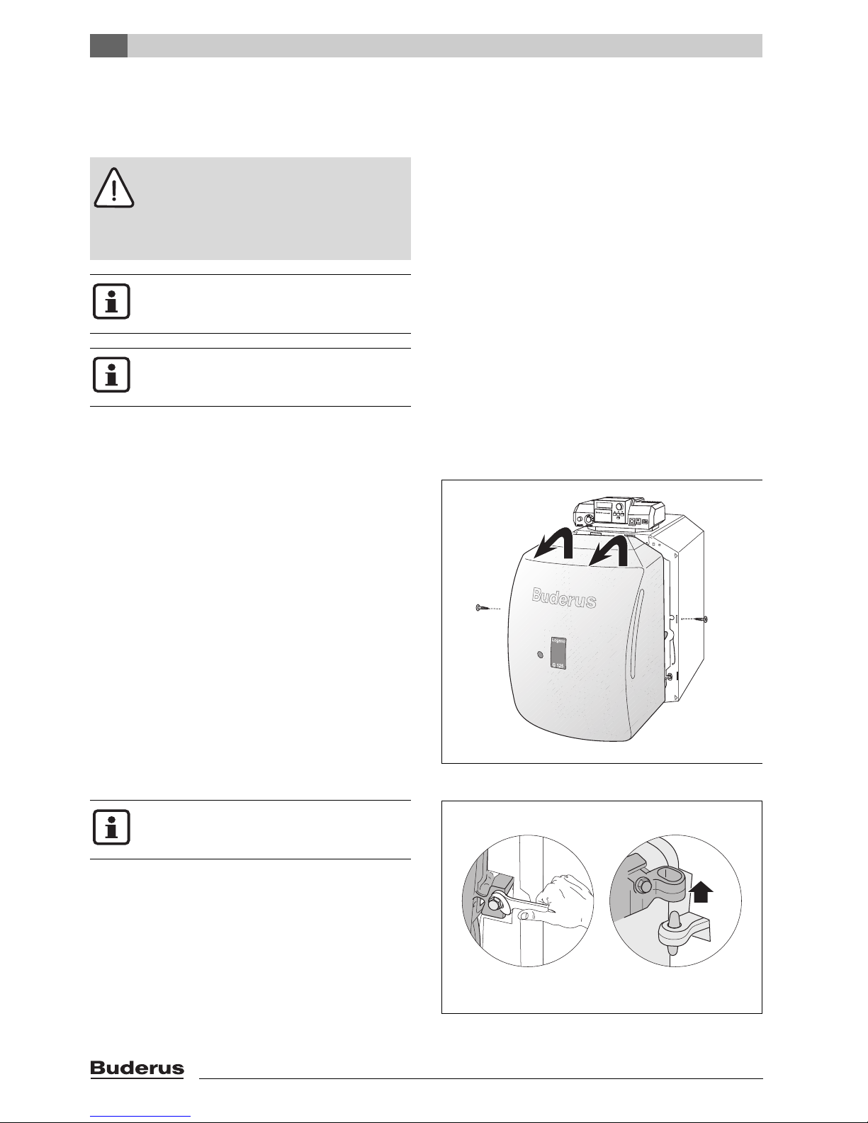
3.1 Reducing the boiler weight for handling purposes
If required, you can reduce the weight of the boiler by
removing the burner hood and door.
V Unscrew the burner-hood screws.
V Lift burner hood slightly and draw forwards to remove.
V Before removing the burner door: unplug the burner
plug from the burner control unit.
Fig. 4 Removing burner cover
Prevent the burner door from falling over and
damaging the burner and blast tube.
V Unscrew two hex-head bolts at the sides.
V Open burner door.
V Lift the burner door off its hinges.
Logano GB125 BE US/CA - Technical specifications are subject to change without prior notice.14
7 747 019 141-04.1RS
Fig. 5 Removing the burner door
3.2 Lifting and carrying the boiler
The boiler is secured to the pallet by
2 screws for transportation purposes.
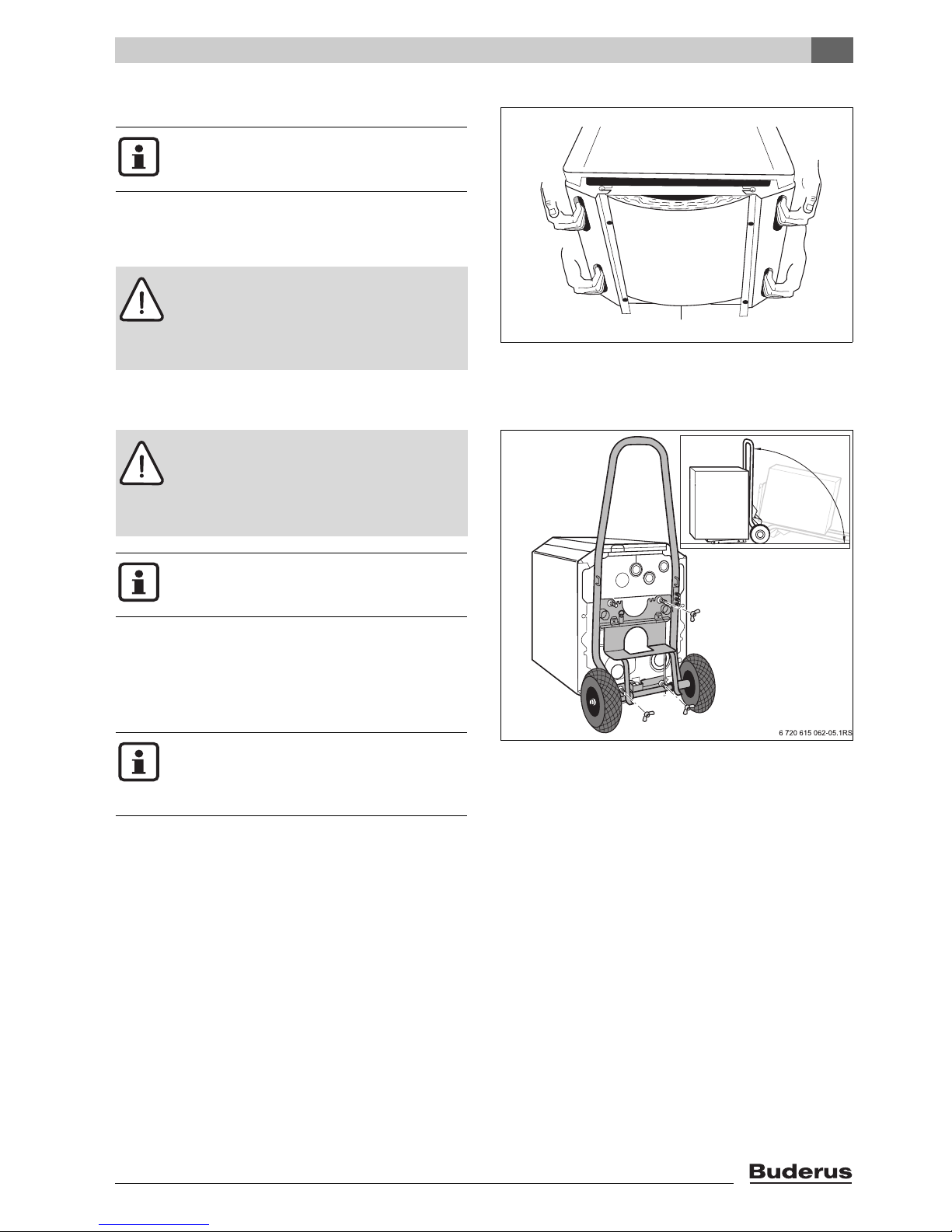
The boiler can be held and carried at the grip positions
shown (Fig. 6).
V Undo the transit screws.
Warning: Risk of injury from carrying heavy
loads.
V Always lift and move the equipment with
the assistance of another person using the
handle positions shown.
3.3 Moving the boiler with hand truck
Warning: Risk of injury if load is inadequate-
ly secured during transportation.
V Use suitable means of transportation, e.g.
the Buderus boiler hand truck with strap.
V Secure the load against falling.
Moving the boiler
Bottom of boiler
Fig. 6 Lifting and carrying the boiler
3
7 747 019 141-05.1RS
You can order the boiler hand truck from your
Buderus distributor.
Moving the boiler with hand truck (Fig. 7)
V Place the hand truck (e.g. boiler trolley or sack truck) at
the back of the boiler.
V Secure boiler to hand truck using strapping.
V Move the boiler to the installation location.
The boiler trolley can also be used to facilitate
work on the underneath of the boiler, e.g. fitting the adjustable feet (Æ Chapter 4.3,
page 18).
Fig. 7 Moving the boiler with a boiler hand truck
Logano GB125 BE US/CA - Technical specifications are subject to change without prior notice. 15
4
Placing the boiler
4 Placing the boiler
This chapter describes how to install and place the boiler
in the boiler room.
Caution: Risk of system damage due to
freezing.
V Install the heating system in a frost-free
room.
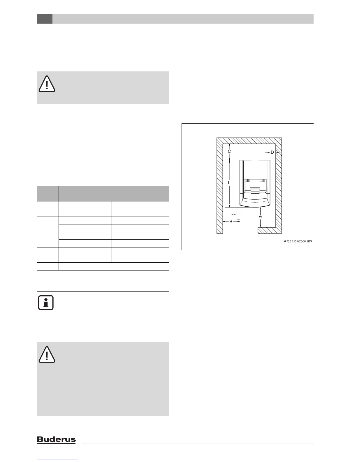
4.1 Wall clearances
Wherever possible, position the boiler with the recommended wall clearances. Reducing the minimum clearances makes the boiler more difficult to access.
The boiler base or foundation must be perfectly flat and
level.
The burner door is factory-fitted with the hinges on the
right. The burner door can be converted to left hand
closing.
Dimension
A Recommended 40"
minimum 27"
B Recommended 27"
minimum 16"
C Recommended 28"
minimum 20"
D Recommended 16"
minimum 6"
L Æ Chapter 2.6.1, page 10
Tab. 9 Recommended and minimum wall clearances
(dimensions in inches)
The boilers are designed for a side clearance
of 6 ".
Where applicable, allow extra wall clearances for additional components such as DHW
tank pipe connections, flue silencer, other
flue components, etc.
Warning: Risk of fire from flammable materials or liquids.
V Clearances less than 6" must comply with
local and statutory codes.
V Make sure that there is a sufficient clear-
ance between combustible materials and
the chimney connection as specified by
NFPA 31 (distance of 18 ").
V The floor must comply with the require-
ments of NFPA 31.
Wall clearance
Fig. 8 Wall clearances in the boiler room (boiler posi-
tioned on the right-hand side)
Logano GB125 BE US/CA - Technical specifications are subject to change without prior notice.16
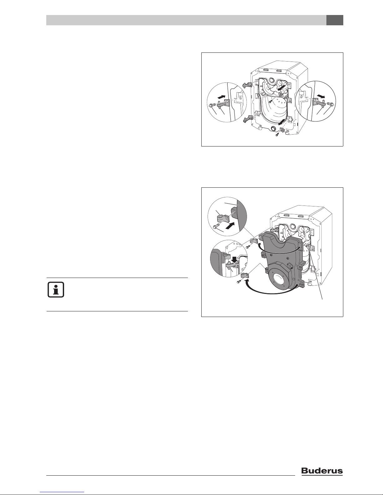
4.2 Reversing the burner door
The burner door is factory-fitted with the hinges on the
right – the burner door opens to the right. You can change
the burner door hinges over to the left-hand side if
required to suit the installation site.
Requirement: the burner hood must have been removed
first (Æ Chapter 3.1, page 14).
V Removing the burner door (Æ Chapter 3.1, page 14).
V Unscrew the hinge-pin bolts [1] and remove the hinge
pins [2].
V Fix the hinge pins [2] on the left-hand side of the boiler
using the hinge-pin bolts.
V Unscrew the hinge-barrel bolts [1] and remove the
hinge barrels [2].
V Fix the hinge barrels [2] on the left-hand side of the
burner door [3] using the hinge-barrel bolts.
V Hang the burner door [3] by locating the hinge barrels
[2] on the hinge pins [4].
V Check that the heat exchanger baffles are placed hori-
zontally (Æ Chapter 6.3, page 34).
V Close the burner door [3] and secure with the two hex-
agon-head bolts. Tighten the hexagon-head bolts
evenly (approx. 90 lb ins) so that the burner door seals
properly.
If the burner door hinges have been changed
over to the left-hand side, the burner cable
must be disconnected from the burner before
opening the burner door.
Placing the boiler
12 21
7 747 019 141-08.1RS
Fig. 9 Reversing the burner door (boiler heat
exchanger attachments)
1 Hinge bolts
2 Hinges
3
2
1
4
7 747 019 141-09.1RS
4
5
Logano GB125 BE US/CA - Technical specifications are subject to change without prior notice. 17
Fig. 10 Reversing the burner door (door attachments)
1 Hinge-barrel bolts
2 Hinge lobes
3 Burner door
4 Hinges
5 Heat exchanger baffle plates
4
Placing the boiler
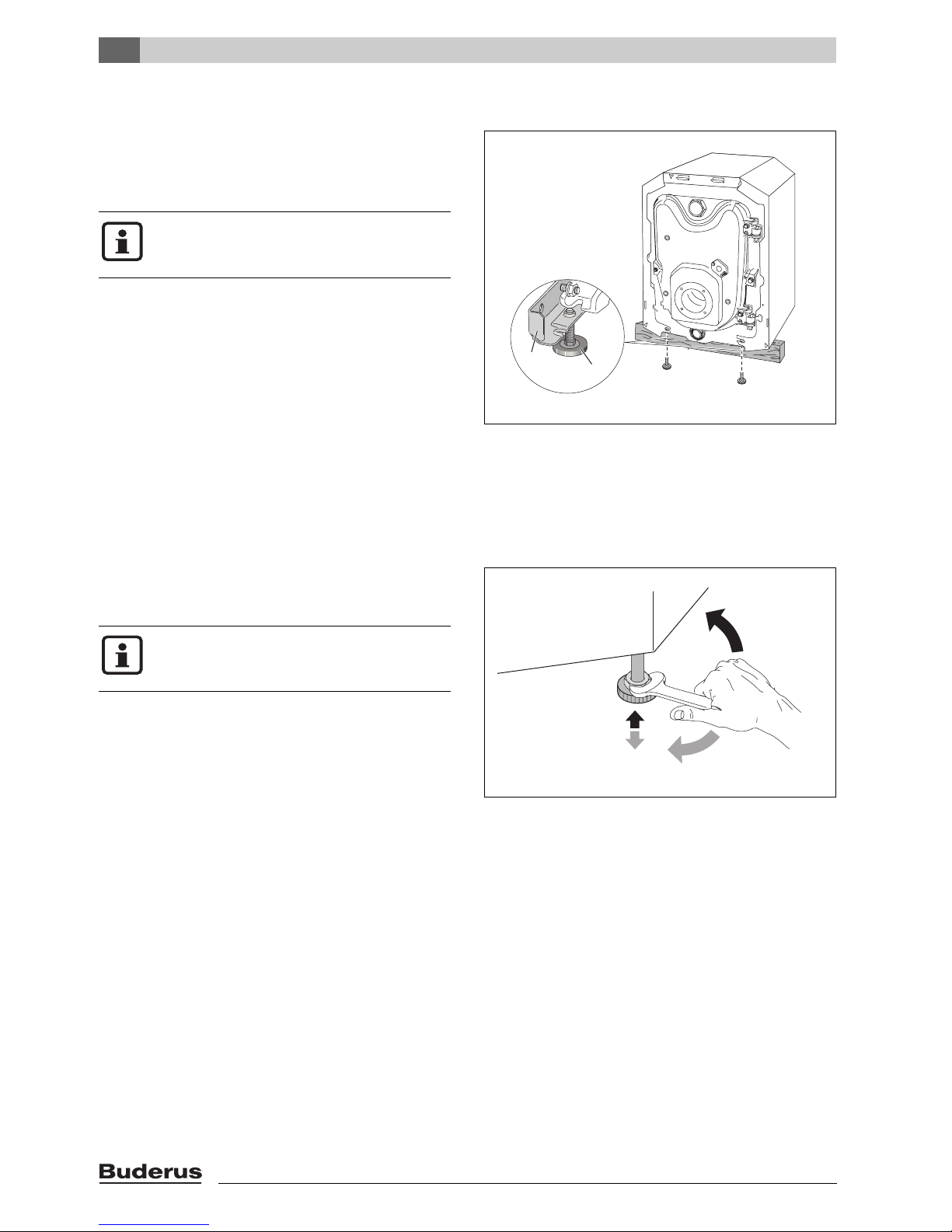
4.3 Mounting the adjustable feet (included with B-kit)
Level the boiler by turning the adjustable feet to prevent
air pockets becoming trapped inside the boiler.
Requirement: the burner hood or burner door panel must
have been removed first (Æ Chapter 3.1, page 14).
If the boiler is mounted on top of a horizontal
hot water tank the adjustable feet are not
used.
V Tilt the boiler with the aid of a hand truck or trolley
(Æ Chapter 3.3, page 15) or place a wooden batten
underneath to jack it up.
V Screw in adjustable feet [2] ¼" – 1/8".
V Gently set the boiler down.
1
Fig. 11 Fitting the adjustable feet
(burner not shown)
1 Angle bracket
2 Adjustable feet
2
7 747 019 141-10.1RS
4.4 Positioning and leveling the boiler
V Position the boiler in its final location.
V Level the boiler by rotating the adjustable feet as
required and using a level.
Protect boiler connections from damage and
dirt if the boiler is not to be installed immediately.
7 747 019 141-11.1RS
Fig. 12 Leveling the boiler
Logano GB125 BE US/CA - Technical specifications are subject to change without prior notice.18
5 Boiler installation
Boiler installation
5
This chapter details how to install your boiler correctly.
This involves the following steps:
– Connecting the venting system
– Providing air supply for combustion
– Connecting the water pipes
– Making the electrical connections
– Connecting the fuel supply
Danger: Risk of fatal injury from toxic flue
gases.
V Never connect more than one boiler to a
flue system – regardless of whether the
flue is vertical or horizontal.
V Common venting appliances can cause
damage to property and personal injury.
V Do not route the flue system through an-
other flue system that is in use, e.g. a masonry chimney connected to a wood
stove.
V Follow the instructions of the flue pipe
manufacturer.
The boiler must be installed by a trained and
certified installer in accordance with all requirements of NFPA-31, "Installation of OilBurning Equipment". Installation must comply with all local and national codes applicable to the installation of oil-fired boilers.
5.1 Flue pipe installation
The overall burner air supply/boiler flue pipe system conforms to the types of oil combustion equipment listed in
the table below.
Observe the national standards and regulations for operating oil-fired appliances.
Installation
Type
Tab. 10 Types of installation
Combustion air supply and flue system
I Concentric combustion air supply and flue
pipe exiting horizontally through external wall.
Combustion air supply and flue systems are
part of the combustion equipment.
II Concentric combustion air supply and flue
pipe system exiting vertically through roof.
Combustion air supply and flue systems are
part of the combustion equipment.
III Vent pipe installed inside a masonry chimney.
The space around the vent pipe is used for
combustion air.
In Canada, the requirements of CSA/CGAB139.1 and 2 Installation Codes apply.
The GB125 boiler is approved for zero (0")
clearance between its concentric vent pipe
and combustibles.
Because of the tight construction of modern
houses, this boiler must draw all air supply for
combustion from outside (RLU).
Logano GB125 BE US/CA - Technical specifications are subject to change without prior notice. 19
5
Boiler installation
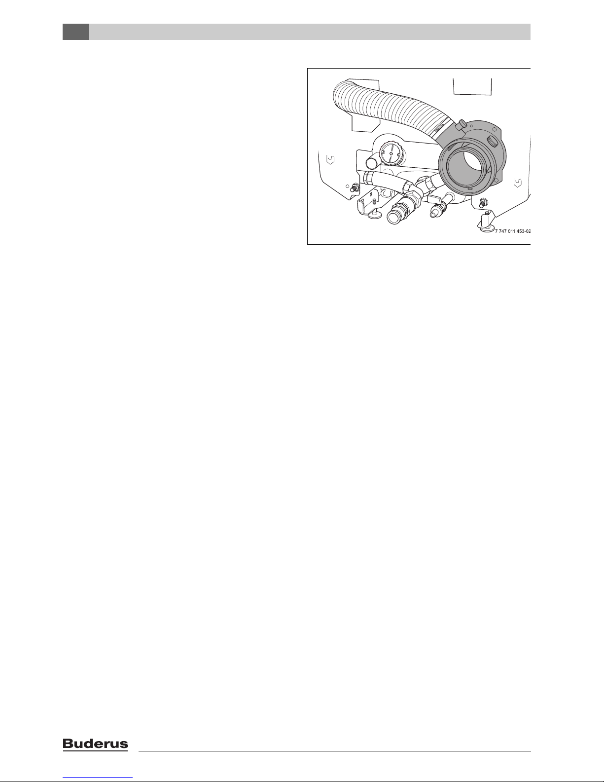
5.2 Test ports
Flue gas readings and combustion air temperature readings are taken exclusively at the dedicated testing ports.
Follow the directions in the instructions for the Logatop
BE oil burner.
Fig. 13 Fitting the flue/air pipe socket
Logano GB125 BE US/CA - Technical specifications are subject to change without prior notice.20
 Loading...