

Buderus GB162-100, GB162-80 Installation Instructions Manual
Please read thoroughly before starting installation
7217 5800 – 01/2006 GB (EN) For heating engineers
Installation instructions
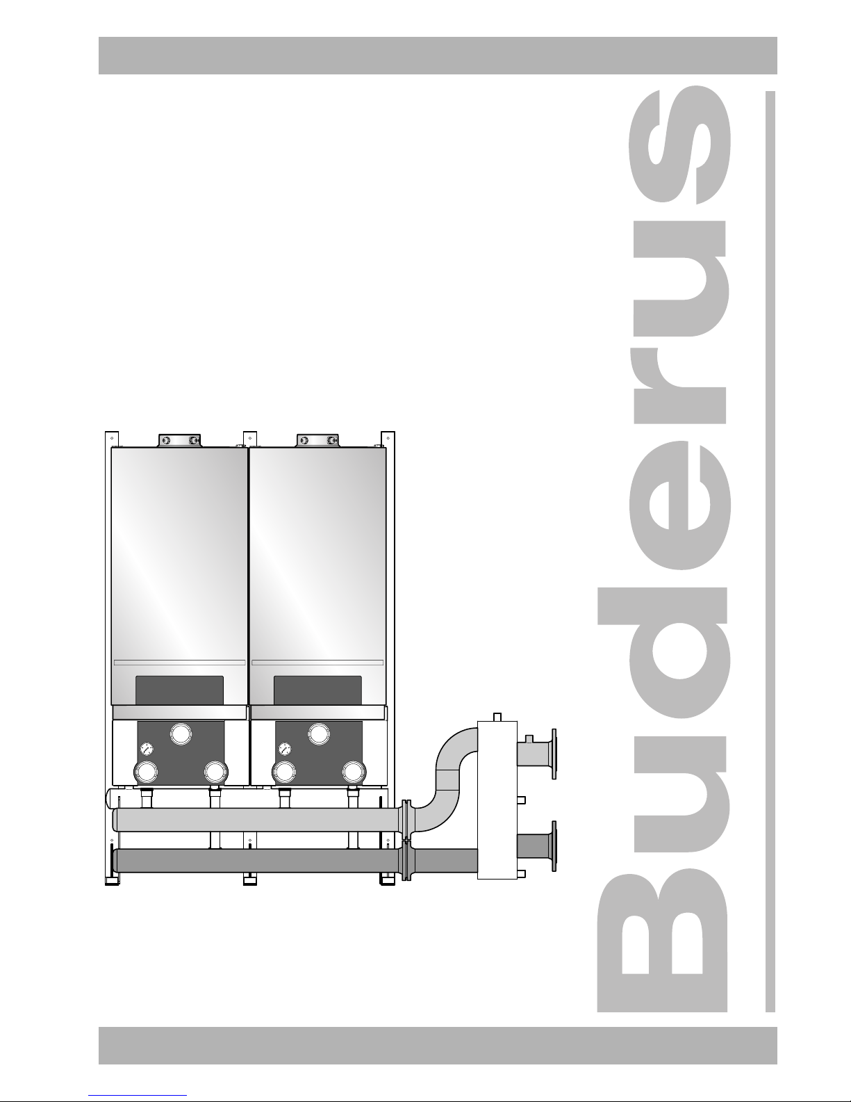
Logamax plus GB162-80/100
cascade unit
2
W • http://www.buderus-commercial.co.uk We reserve the right to make technical modifications.
Installation instructions Logamax plus GB162-80/100 cascade unit • Version 01/2006
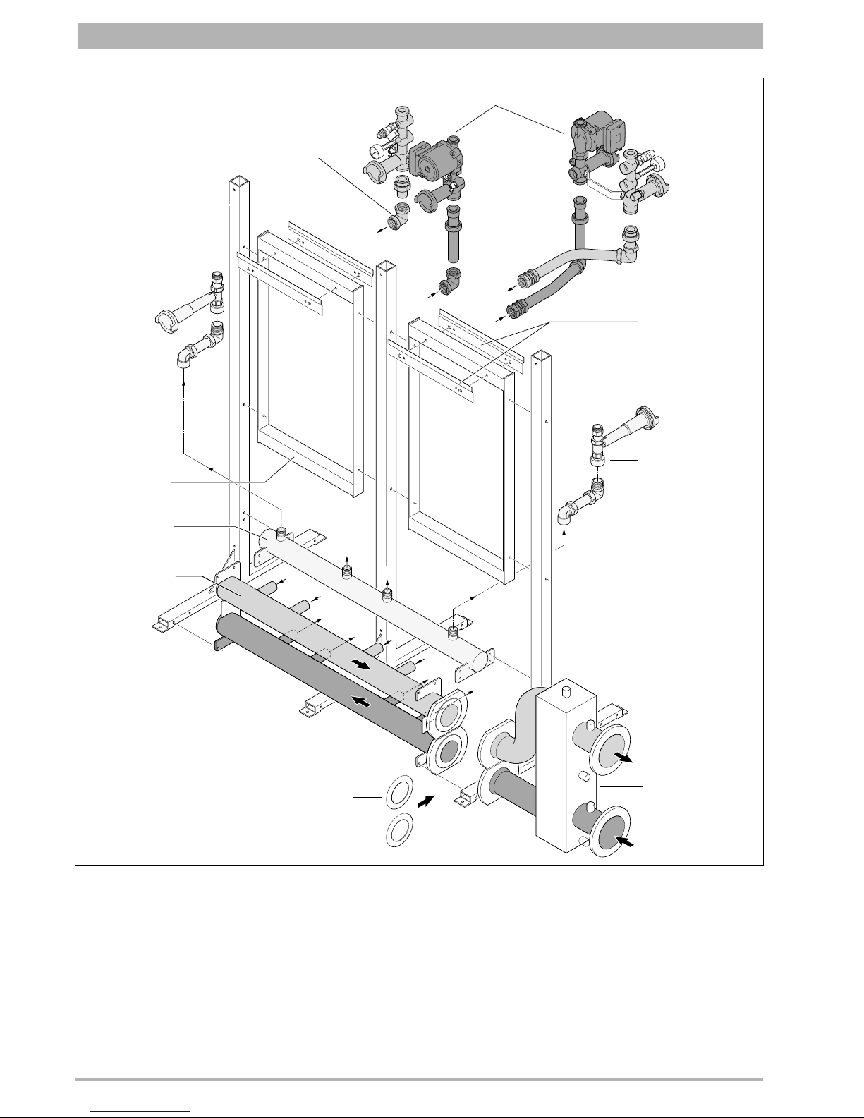
Fig. 1 Overview of Logamax plus GB162 cascade frame
Item 1: Supports
Item 2: Connecting frame
Item 3: Main gas pipe
Item 4: Flow and return header
Item 5: Gas connection kit TL-inline
Item 6: Mounting bracket
Item 7: Boiler connection set TL-inline
Item 8: Boiler connection set TR-back-to-back
Item 9: Boiler assembly connection kit
Item 10: Gas connection kit TR-back-to-back
Item 11: Flange seals
Item 12: Low loss header
B2
B1
A1
A1
B1
B2
A2
C2
C1
C1
C2
A2
A1
A2
B1
B2
9
7
1
5
2
3
4
11
12
10
6
8

3
We reserve the right to make technical modifications. W • http://www.buderus-commercial.co.uk
Installation instructions Logamax plus GB162-80/100 cascade unit • Version 01/2006
List of contents
1 General points . . . . . . . . . . . . . . . . . . . . . . . . 4
2 Items supplied with unit . . . . . . . . . . . . . . . . 4
3 Dimensions. . . . . . . . . . . . . . . . . . . . . . . . . . . 6
4 Cascade frame installation . . . . . . . . . . . . . . 8
4.1 Boiler assembly and pump group installation . . . . . 9
4.2 Installing the insulation . . . . . . . . . . . . . . . . . . . . . 10
4
W • http://www.buderus-commercial.co.uk We reserve the right to make technical modifications.
Installation instructions Logamax plus GB162-80/100 cascade unit • Version 01/2006
General points1
1 General points
The installation instructions for cascade systems with
Logamax plus GB 162 appliances are provided to enable
correct and easy installation.
The modular cascade frame consists of a number of supports
with connecting frames which are screwed together during
installation.
The compact dimensions of the individual cascade frame parts
enable simple and quick installation.
2 Items supplied with unit
Cascade frame (fig. 1):
– Supports
– Connecting frame
– Main gas pipe
– Flow and return header
– Boiler connection kit
– Flange seals
– Low loss header
– Blank flanges
– Rubber pump seals
– Fixings
– Installation instructions
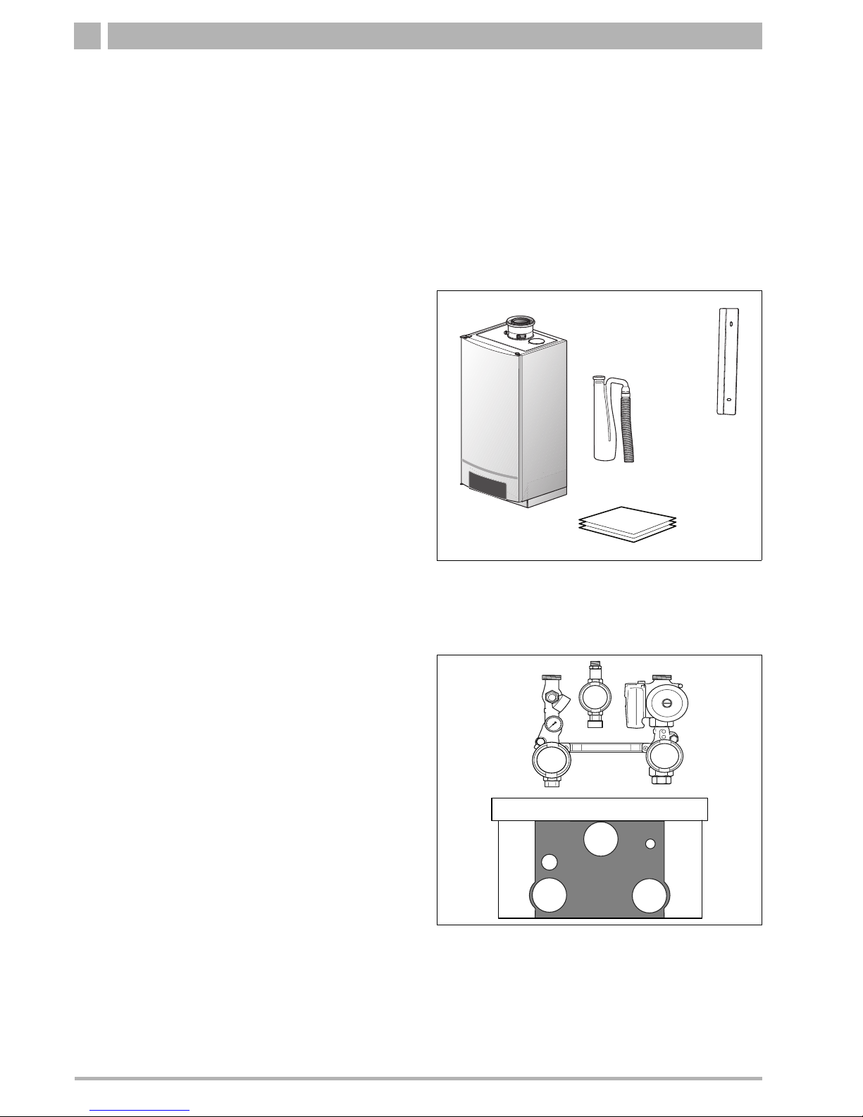
Boiler (fig. 2):
(to be ordered from your supplier)
– Mounting bracket
–Boiler
– Siphon
– Installation instructions.
Pump group (fig. 3):
(to be ordered from your supplier)
– Connection kit
– Installation instructions
The connection kit consists of:
– Maintenance valves
– Drain cock
– Gas isolation valve
– Pressure relief valve
– Non-return valve
–Pump
– Pressure gauge.
Fig. 2 Items supplied with the boiler assembly
Fig. 3 Items supplied with pump group
 Loading...